

Page 1
Service Bulletin
Title: DCM-1 Power Cycle Update
Bulletin #: DCM0001 Issue Date: January 30, 2001
Models Affected: DCM-1 Bulletin Revision: A
Production Range: January 1999–August 2000 (serial # range: see “Units Affected,” below)
Description
When the DCM-1 is turned off and then turned on again within 15 seconds, the front panel LEDs do not respond to the monitor selector
buttons. Any amplifiers connected to the DCM remain in standby. If the DCM-1 is turned off and after 15 seconds, turned on again, the
unit will operate as normal.
Units Affected
Only DCM-1 units manufactured from January 1999 through August 2000 are affected. The first four digits of the serial number
indicate the year and week of manufacture in YYWW form (e.g., “0021” is the 21st week of the year 2000). Thus, the units affected by
this bulletin have serial numbers between 9901xxx and 0024xxx.
Instructions
Tools and materials required:
• Grounded anti-static wrist band and work surface
• Personal computer with Windows (95/98/2000/NT/ME) operating system and Lattice Semiconductor ispVM™ System software
(downloadable from Lattice Semiconductor’s web site: http://www.latticesemi.com) and QSC DCM Commander software
installed
• ispDOWNLOAD™ cable and parallel port interface box (available from Lattice Semiconductor)
• RS-232 serial cable (straight through)
• DataPort cable
• JEDEC file containing the update code (available from QSC Technical Services)
• 0.031" (0.8 mm) diameter rosin-core solder
(60/40 or 63/37 eutectic type)
• Soldering iron with fine tip
• Desoldering equipment or solder braid
• 8-pin, 0.1”-center right-angle male header (QSC
part # CO-000083-00, a 10-pin right-angle
header; prepare by cutting off 2 pins at one end)
• DCM input test cable (see last page)
• DCA amplifier
• 8-ohm resistive load with power rating
adequate for the DCA amplifier
• Sinusoidal audio signal generator
• Oscilloscope
CAUTION: Take appropriate anti-static
precautions to guard against electrostatic
discharge (ESD).
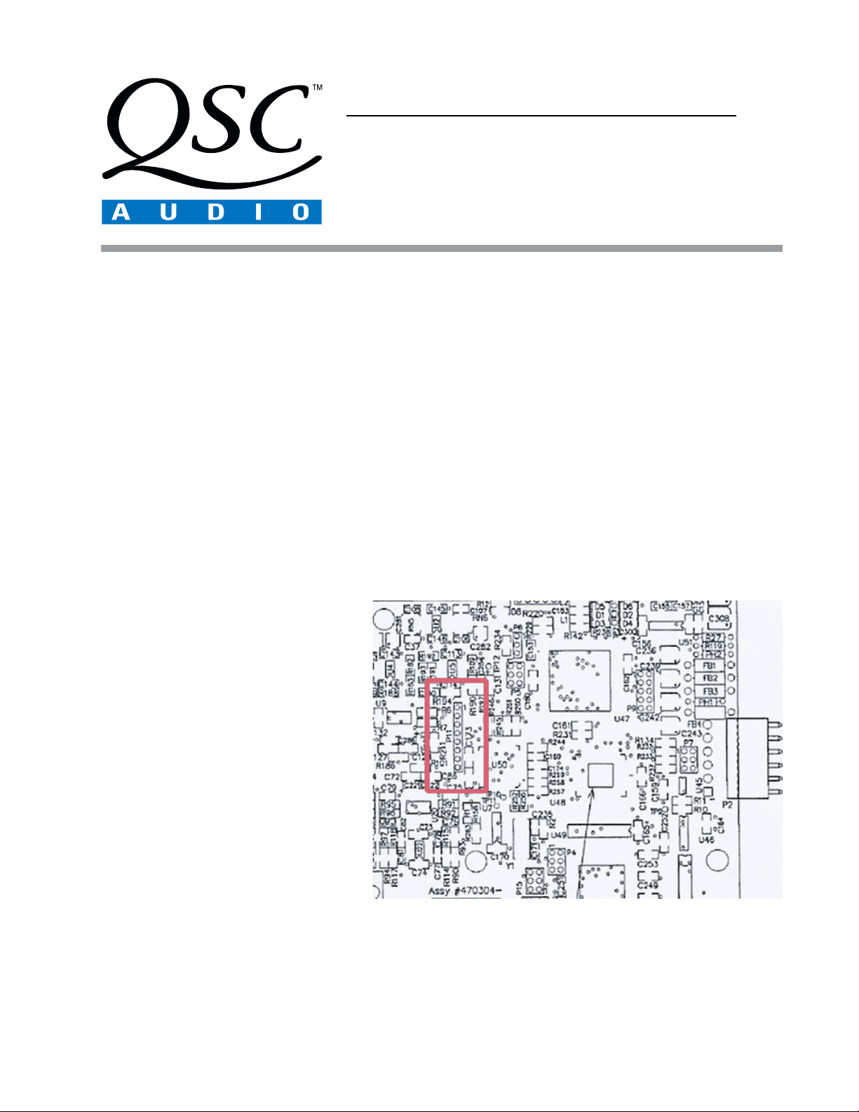
Figure 1. Locate and remove solder from the eight pads at P11 (inside the
rectangle). The component side of the rear panel PCB is shown.
Procedure: Installing the download header
1. Connect the DCM-1 to the computer’s RS-232 port via the serial cable. Turn on the DCM-1 and verify that it operates properly. If
the front panel stops responding, turn off the unit, wait 15 seconds, and turn it back on. Once the DCM-1 is functioning correctly,
open the DCM Commander application on the computer.
DCM0001 1
Page 2
2. Select Connect to DCM from the Communication menu.
Then select Read Configuration from DCM, also from the
Communication menu. This will load the configuration
parameters currently programmed into the DCM-1 into the
DCM Commander application.
3. Select Save as … from the File menu. Choose a filename
and location, and save the configuration. This configuration
will be restored to the DCM-1 later, after the modification and
testing are done.
4. Turn off the DCM-1 and remove the 11 screws securing the
top cover of the DCM-1, and then lift off the cover.
5. Locate P11 on the back side of the rear panel printed circuit
board (PCB) and remove the solder from the eight pads (Figure
1). P11 is easier to find if you remove the PCB, but if you already are familiar with its location you can save time by leaving the
PCB attached to the chassis.
6. The right-angle header can be installed either way, with the pins pointing left or right. Solder the header in place at P11. The
square pad is pin 1 (toward the top of the PCB). Locate pin 5 and cut it off.
7. Connect the header at P11 to the PC’s parallel port via the ispDOWNLOAD cable and parallel port interface box.
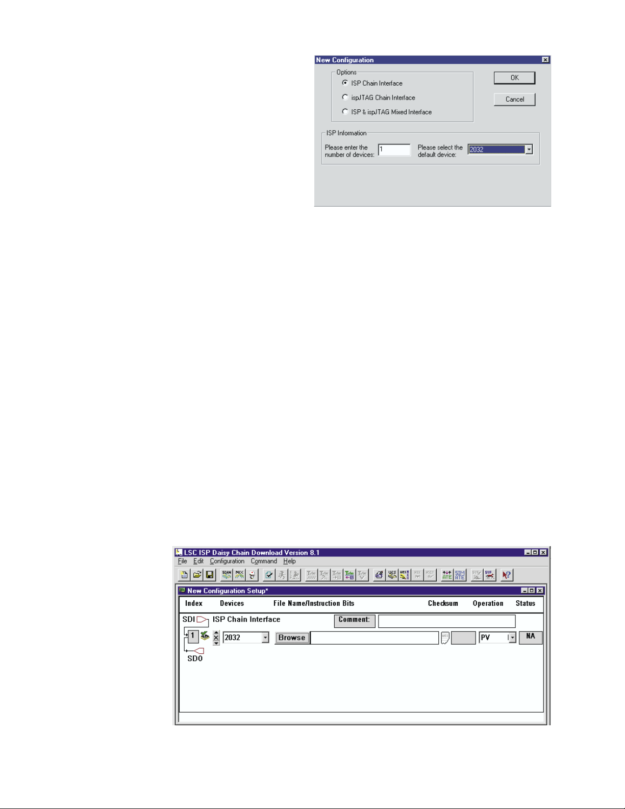
Figure 2. Select the correct device.
Procedure: Downloading the JEDEC code
1. Open the ispVM System application. Click the ispDCD button to open the daisy chain download program. Select New from the
File menu.
In the New Configuration dialog box, select the ISP Chain Interface option. Under ISP Information, enter 1 as the number of
devices, and select the 2032 chip as your default device (Figure 2).
2. In the New Configuration Setup window, click the Browse button. Search for the correct JEDEC file and see that the file path
appears in the text box to the right of the Browse button (Figure 3).
3. In the Operation list, select PV.
4. Now turn the DCM-1 on and wait about 3 seconds for it to complete its turn-on sequence.
5. In the ispVM System application, press CTRL+R or click the run button. After downloading the new code, the application will display
some text in the Messages window and also a word in the Status box that indicates whether the operation was successful:
“Pass” means the new code has been downloaded without error, while “Fail” means some problem occurred. If the download was
unsuccessful, make
sure the DCM-1 has AC
power and the
ispDOWNLOAD cable
is oriented and
connected correctly,
and then start the
procedure over again.
6. Turn off the DCM-1 and
disconnect the
ispDOWNLOAD cable.
Figure 3. Browse for the JEDEC update file. When you select the file, the path will appear in the text
box to the right of the Browse button.
2 DCM0001
Page 3

Procedure: Test and Verification
1. Connect the DCA amplifier to Port A of the DCM-1 via a
DataPort cable. Attach the 8-ohm load to the output of
amplifier Channel 1. Connect the RS-232 cable
between the DCM-1 and the computer’s serial port.
2. Turn the DCM-1 on and wait a few seconds. Turn it off
and within 15 seconds, turn it on again. Verify that the
front panel controls operate properly.
3. Clear all monitor selections (all the monitor LEDs on
the front panel should be off) and open the DCM
Commander application. Select Serial Port Selec-
tion from the Communication menu and choose the
appropriate serial port. The DCM Commander
application opens with a default configuration that
sets crossovers for the left, center and right zones at
1500 Hz; leave these settings as they are for this test.
Table 1. DCM-1 channel and port assignments.
For each port, select the model number that corresponds to the test DCA amplifier on Port A.
4. Attach the oscilloscope probe to the loaded output of the test DCA amplifier and turn the amplifier’s gain controls up all the way.
Turn the amplifier on.
5. Put a 3-volt sinusoidal test tone into the Left input of the DCM-1 (see the Appendix on the last page for a description of the input
connection). Use a frequency far enough below the 1500 Hz crossover point to be unattenuated by the filter—for example, 1 kHz
or lower. Verify that the signal passes to the amplifier’s output on Channel 1, and that the output voltage corresponds to the
amplifier’s 8-ohm power rating (see Table 2 below; use RMS voltages if you are measuring with a meter, and peak values if you are
using the oscilloscope).
6. Turn off the test tone and connect the load resistor and oscilloscope to the other channel. Change the generator frequency to 2500
Hz or higher and check the output of amplifier Channel 2. The voltage should also correspond to the maximum rated power level.
7. Repeat steps 5 and 6 with the Center (Port B) and Right (Port C) screen channels. See Table 1 for specific channel and port
asssignments.
8. Also check the Subwoofer (Ports G and H) channels and the Surround Left and Surround Right (Ports M, N, and O) channels. These
channels have no crossover, so a mid frequency will be suitable as a test tone. Verify that the output voltages correspond to full
rated power.
troP1-MCD noitpircseD 1lennahC 2lennahC
A
B
C
G
H
M
N
O
tfeLycneuqerfwoLycneuqerfhgiH
retneCycneuqerfwoLycneuqerfhgiH
thgiRycneuqerfwoLycneuqerfhgiH
refoowbuS1buS2buS
refoowbuS1buS2buS
dnuorruS1tfeLdnuorruS1thgiRdnuorruS
dnuorruS2tfeLdnuorruS2thgiRdnuorruS
dnuorruS
)llawkcab(
3tfeLdnuorruS3thgiRdnuorruS
ledoM V
2221ACDV04
2261ACDV94
2242ACDV85
2203ACDV66
2243ACDV57
4461ACDV54
4281ACDV73
TUO
RMS
RMS
RMS
RMS
RMS
RMS
RMS
8@rewoplluf( Ω)
kaepV65;
kaepV96;
kaepV28;
kaepV49;
kaepV601;
kaepV36;
kaepV25;
Table 2. The full-power (@ 8 ohms)
output voltages of the DCA
amplifier models.
Figure 4. This screen indicates the configuration was successfully transferred to the DCM-1.
DCM0001 3
Page 4

9. Turn off the amplifier and disconnect it from the DCM-1. Also disconnect the audio generator.
10. In the DCM Commander application, select Open from the File menu. Select the configuration file you saved earlier. Download
the configuration to the DCM-1 by selecting Write Configuration to DCM from the Communication menu. The application will
inform you that the configuration was transferred successfully (Figure 4).
11. Turn off the DCM-1, disconnect the cables, and reinstall the top cover. The unit may be returned to use.
Appendix: DCM input test cable
For inputs the DCM-1 uses a female DB25 connector that connects to a cinema processor via a
standard interconnect cable. To test the DCM-1, you will need a way to connect the audio signal
generator to its six inputs.
The illustration at right shows the pinout of the DB25 connector. You will need a male
DB25 connector, and you will need to attach the six inputs as shown. Each input pair
is on adjacent pins; for example, Left + is on pin 2, while Left - is on pin 14, just
below and to the right.
The input pairs are as follows:
Left: 2 = +; 14 = Center: 5 = +; 17 = Right: 8 = +; 20 = Subwoofer: 25 = +; 12 = Surround left: 23 = +; 10 = Surround right: 24 = +; 11 = -
The inputs for the Left center and Right center screen channels are
not used on the DCM-1.
On each pair, use wire and a connector that is appropriate for your audio
generator. If the audio generator output is unbalanced, connect each (-) terminal
of the balanced inputs—Left, Center, Right, and Subwoofer—to a chassis ground
terminal as well. One option is to build the cable with a single connection for the audio
generator and use a six-way switch (or eight-way, if you wish to use it for testing other
DCM models) to connect it to the input you are testing.
ispDOWNLOAD and ispVM are trademarks of Lattice Semiconductor Corporation.
All other trademarks are the property of their respective owners.
Chassis ground
Input: Subwoofer Input: Surround right Input: Surround left -
Chassis ground
Input: Right +
Chassis ground
Input: Right center -
Input: Center +
Chassis ground
Input: Left center -
Input: Left +
Chassis ground
DB25
female
on DCM
chassis
Input: Left -
Chassis ground
Input: Left center +
Input: Center -
Chassis ground
Input: Right center +
Input: Right -
unused
Chassis ground
Input: Surround left +
Input: Surround right +
Input: Subwoofer +
Contact information
If you need any further information regarding this service procedure, please contact QSC Technical Services at the addresses or
numbers below. You can also order CM16 parts; to expedite processing please use the correct part number when ordering.
Telephone:
Fax:
E-mail:
Web Site: www.qscaudio.com (product info/support)
Postal and parcel address:
4 DCM0001
1-800-772-2834 (within USA only)
+1 714-957-7150
+1 714-754-6173
tech_support@qscaudio.com
www.qscstore.com (on-line accessory and replacement component sales)
QSC Audio Products, Inc.
Technical Services Group
1665 MacArthur Blvd.
Costa Mesa, CA 92626 USA
 Loading...