

Page 1

CXD Amplifiers
User Manual
CXD4.2 — 4 Channel, 2000 W Amplifi er
CXD4.3 — 4 Channel, 4000 W Amplifi er
CXD4.5 — 4 Channel, 8000 W Amplifi er
TD-000367-01 -B
*TD-000367-01*
Page 2
EXPLANATION OF SYMBOLS
The term “WARNING!” indicates instructions regarding personal safety. If the instructions are not followed the result may be bodily injury or death.
The term “CAUTION!” indicates instructions regarding possible damage to physical equipment. If these instructions are not followed, it may result in
damage to the equipment that may not be covered under the warranty.
The term “IMPORTANT!” indicates instructions or information that are vital to the successful completion of the procedure.
The term "NOTE" is used to indicate additional useful information.
The intent of the lightning fl ash with arrowhead symbol in a triangle is to alert the user to the presence of un-insulated "dangerous"
voltage within the product's enclosure that may be of suffi cient magnitude to constitute a risk of electric shock to humans.
The intent of the exclamation point within an equilateral triangle is to alert the user to the presence of important safety, and operating
and maintenance instructions in this manual.
IMPORTANT SAFETY INSTRUCTIONS
WARNING!:
TO PREVENT FIRE OR ELECTRIC SHOCK, DO NOT EXPOSE THIS EQUIPMENT TO RAIN OR MOISTURE.
1. Read these instructions.
2. Keep these instructions.
3. Heed all warnings.
4. Follow all instructions.
5. Do not use this apparatus near water.
6. Clean only with a dry cloth.
7. Do not block any ventilation opening. Install in accordance with the manufacturer’s instructions.
8. Do not install near any heat sources such as radiators, heat registers, stoves, or other apparatus (including amplifi ers) that produce heat.
9. Do not defeat the safety purpose of the polarized or grounding-type plug. A polarized plug has two blades with one wider than the other. A
grounding type plug has two blades and a third grounding prong. The wide blade or the third prong are provided for your safety. If the provided
plug does not fi t into your outlet, consult an electrician for replacement of the obsolete outlet.
10. To reduce the risk of electrical shock, the power cord shall be connected to a mains socket outlet with a protective earthing connection.
11. The appliance coupler, or the AC Mains plug, is the AC mains disconnect device and shall remain readily operable after installation.
12. Protect the power cord from being walked on or pinched particularly at plugs, convenience receptacles, and the point where they exit from
the apparatus.
13. Only use attachments/accessories specifi ed by the manufacturer.
14. Unplug this apparatus during lightning storms or when unused for long periods of time.
15. Refer all servicing to qualifi ed service personnel. Servicing is required when the apparatus has been damaged in any way, such as power-supply
cord or plug is damaged, liquid has been spilled or objects have fallen into the apparatus, the apparatus has been exposed to rain or moisture,
does not operate normally, or has been dropped.
16. Adhere to all applicable, local codes.
17. Consult a licensed, professional engineer when any doubt or questions arise regarding a physical equipment installation.
18. Do not use any aerosol spray, cleaner, disinfectant or fumigant on, near or into the apparatus. Clean only with a dry cloth.
19. Do not unplug the unit by pulling on the cord, use the plug.
20. Do not submerge the apparatus in water or liquids.
21. Keep ventilation opening free of dust or other matter.
TD-000367 -01 -B
2
Page 3
Maintenance and Repair
WARNING!:
maintenance and repair methods. To avoid a danger of subsequent damage to the apparatus, injuries to persons and/or the
creation of additional safety hazards, all maintenance or repair work on the apparatus should be performed only by a QSC
authorized service station or an authorized QSC International Distributor. QSC is not responsible for any injury, harm or related
damages arising from any failure of the customer, owner or user of the apparatus to facilitate those repairs.
Advanced technology, e.g., the use of modern materials and powerful electronics, requires specially adapted
FCC Statement
For CXD4.3 and CXD4.5
NOTE:
This equipment has been tested and found to comply with the limits for a Class A digital device, pursuant to Part 15 of the FCC
Rules. These limits are designed to provide reasonable protection against harmful interference when the equipment is operated in a
commercial environment. This equipment generates, uses, and can radiate radio frequency energy and, if not installed and used in
accordance with the instruction manual, may cause harmful interference to radio communications. Operation of this equipment in a
residential area is likely to cause harmful interference in which case the user will be required to correct the interference at his own expense.
For CXD4.2
NOTE:
generates, uses and can radiate radio frequency energy and, if not installed and used in accordance with the instructions, may cause harmful
interference to radio communications. However, there is no guarantee that interference will not occur in a particular installation. If this equipment does
cause harmful interference to radio or television reception, which can be determined by turning the equipment off and on, the user is encouraged to
try to correct the interference by one or more of the following measures:
• Reorient or relocate the receiving antenna.
• Increase the separation between the equipment and receiver.
• Connect the equipment into an outlet on a circuit different from that to which the receiver is connected.
• Consult the dealer or an experienced radio/TV technician for help.
These limits are designed to provide reasonable protection against harmful interference in a residential installation. This equipment
This equipment has been tested and found to comply with the limits for a Class B digital device, pursuant to Part 15 of the FCC Rules.
RoHS STATEMENT
The QSC CXD4.2, CXD4.3 and CXD4.5 amplifi ers are in compliance with European Directive 2011/65/EU – Restriction of Hazardous Substances (RoHS2).
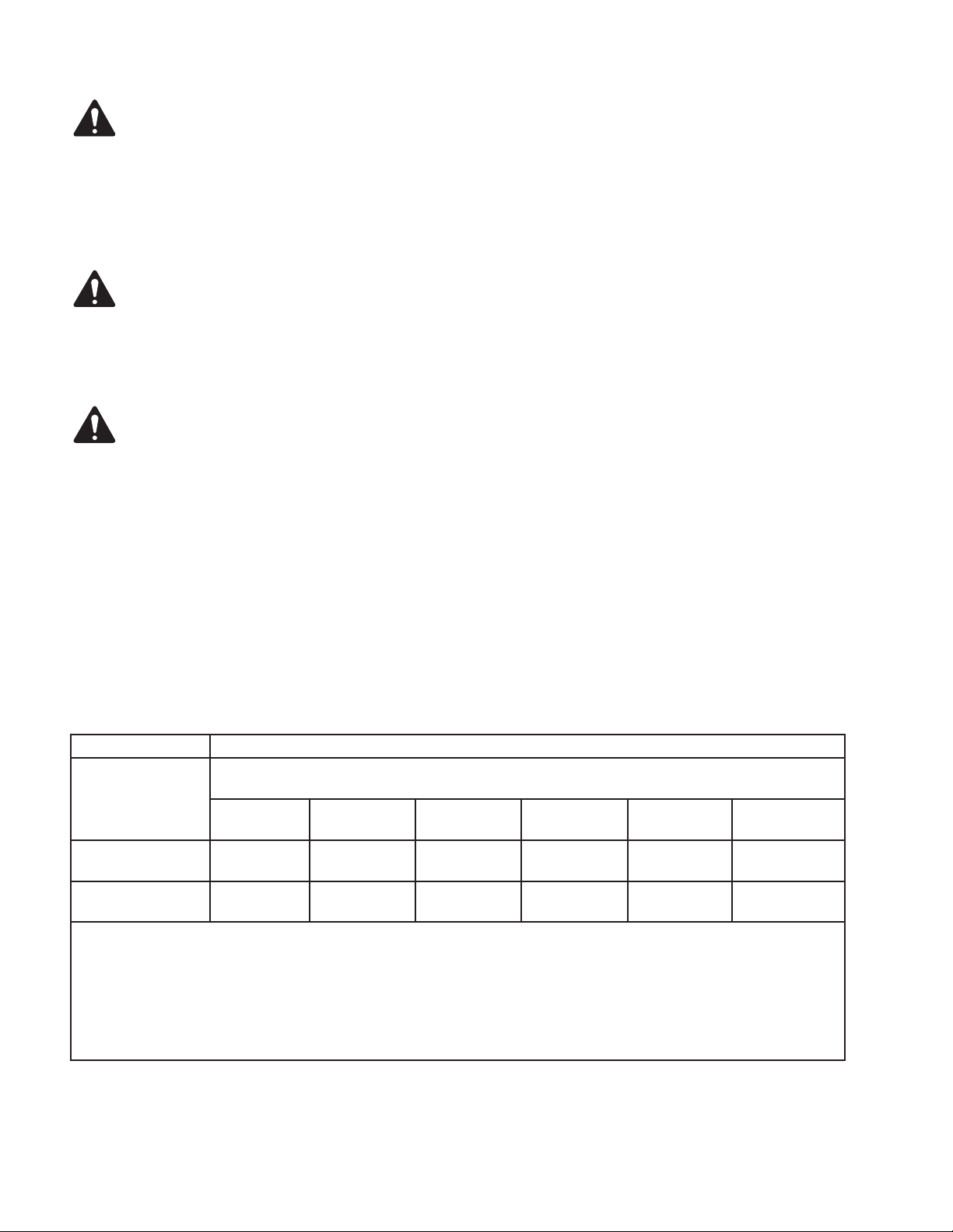
The QSC CXD4.2, CXD4.3 and CXD4.5 amplifi ers are in compliance with “China RoHS” directives. The following chart is provided for product use in
China and its territories:
QSC CXD4.2, CXD4.3, and CXD4.5 Amplifi ers
部件名称
(Part Name)
铅
(Pb)
电路板组件
(PCB Assemblies)
机壳装配件
(Chassis Assemblies)
O: 表明这些有毒或有害物质在部件使用的同类材料中的含量是在 SJ/T11363_2006 极限的要求之下。
XOO O O O
XOO O O O
汞
(Hg)
(Toxic or hazardous Substances and Elements)
有毒有害物质或元素
镉
(Cd)
六价铬
(Cr(vi))
多溴联苯
(PBB)
多溴二苯醚
(PBDE)
(O: Indicates that this toxic or hazardous substance contained in all of the homogeneous materials for this part is below the limit requirement
in SJ/T11363_2006.)
X: 表明这些有毒或有害物质在部件使用的同类材料中至少有一种含量是在 SJ/T11363_2006 极限的要求之上。
(X: Indicates that this toxic or hazardous substance contained in at least one of the homogeneous materials used for this part is above the
limit requirement in SJ/T11363_2006.)
Warranty
For a copy of the CXD warranty, visit the QSC website at www.qsc.com
TD-000367 -01 -B
3
Page 4

Introduction
Built for system integrators, the CXD series amplifi ers provide multi-channel amplifi cation with built-in DSP and enough power to drive wide varieties
of speaker systems with optimal energy effi ciency. The CXD Series consists of three light-weight, 2RU, four-channel amplifi ers with on-board DSP and
fl exible channel combining as well as 70V and 100V direct drive. These amplifi ers not only provide the power and processing to make your system
perform better, they offer outstanding effi ciency ensuring that energy costs are kept to a minimum over the life of the installation.
CXD amplifi ers feature Flexible Amplifi er Summing Technology (FAST). Depending on the model, 2000, 4000, or 8000 Watts of total power can be
distributed across one to four outputs. In addition, the CXD4.3 and CXD4.5, can drive 70V or 100V speaker lines directly from any one or all of the
four outputs, and the CXD4.2 can drive 70V or 100V speaker outputs from bridged channels. This fl exibility allows CXD Series amplifi ers to drive
(for example) two full-range, surface-mounted loudspeakers along with a subwoofer and one 100 V distributed loudspeaker line; or a high-power
subwoofer and a bi-amplifi ed full-range loudspeaker; three 70V distributed loudspeaker lines and a subwoofer; or a single very high-power channel to
drive monster subwoofers.
The CXD Series amplifi ers use QSC’s third-generation class-D power amp design in combination with a custom power stage utilizing a new output
device (4.3 and 4.5 only). In addition, CXD amplifi ers employ the proven PowerLight power supply in conjunction with Power Factor Correction (PFC)
(4.3 and 4.5 only) which aligns the current waveform with the AC mains voltage waveform. PFC enables the CXD Series amplifi ers to draw current
from the wall in a more effi cient and controlled manner resulting in very high power from a single standard AC breaker. Additionally, the CXD Series
amplifi ers offer multi-stage sleep modes saving energy when possible without sacrifi cing performance. The result is an exceptionally powerful and
fl exible platform that offers very high effi ciency.
With four channels of amplifi cation plus signal processing in just 2RUs, the CXD series replaces equipment taking up as much as three times
the rack-space.
A single CXD Series amplifi er is a capable and sophisticated loudspeaker processor. Integration of processing and amplifi cation means that the DSP
knows exactly what the amplifi er is doing so dynamics processing can be far more accurate and effective. This approach employs both RMS and Peak
Limiters that allow the amplifi er and loudspeaker to produce more output without being pushed to distortion or destruction.
The on-board DSP offers four channels of cross-over fi lters, 5-band parametric EQ/Low-shelf/High-shelf, alignment delay and dynamics processing
— everything needed to optimize a loudspeaker system. Additionally when using QSC loudspeakers, CXD amplifi ers provide Intrinsic Correction™, a
combination of fi ltering, limiting and loudspeaker knowhow that was fi rst developed for QSC's WideLine line-array loudspeakers. Intrinsic Correction
compensates for the non-linearity in horn and driver design resulting in exceptional performance.
The CXD also includes manufacturers' recommended tunings for a number of the most popular passive loudspeakers. A system setup wizard helps
you select the right preset, or select one of the 20 confi guration templates and create tunings that you can save in the user preset library.
Whether using the dedicated front panel user interface featuring a 400 x 240 display, rotary encoder and navigation buttons, or the Amplifi er Navigator
software on a PC or Mac, the CXD amplifi ers are an ideal amplifi er/processing platform for installations.
Unpacking
There are no special unpacking instructions. You may want to keep the shipping material for the unlikely event that the amplifi er should need
returning for service.
Package Contents
1. Quick-Start Guide TD-000350
2. Warning Information Sheet TD-000420
3. CXD Amplifi er
4. IEC AC Power Cord
5. Euro-style Connector Plug, 3-pin (4)
TD-000367 -01 -B
6. Euro-style Connector Plug, 8-pin (1)
7. Euro-style Connector Plug, 3.5 mm, 2-pin (1)
8. Euro-style Connector Plug, 3.5 mm, 3-pin (1)
9. USB Cable (1)
4
Page 5
Features
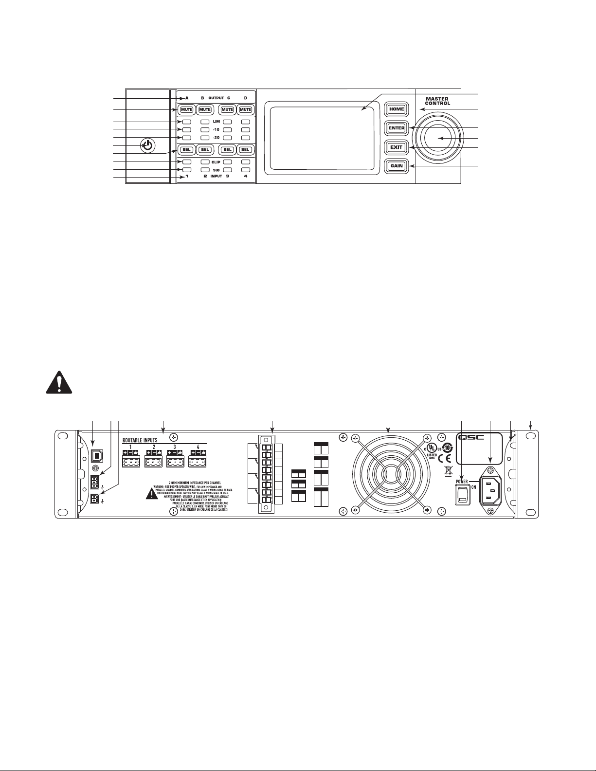
Amplifi er Front Panel
11
12
13
14
15
16
10
1
2
3
4
5
6
7
8
9
— Figure 1 —
1. Output channels are labeled A, B, C, and D
2. Output Channel Mute Buttons and LEDs (Red)
3. Output Channel Limiter LEDs (Red)
4. Output Channel -10 dB below maximum amplifi er output (Blue)
5. Output Channel -20 dB below maximum amplifi er output (Blue)
6. Soft Power Button (Blue/Red)
7. Channel Select Buttons and LEDs (Amber for Input, Blue for Output)
8. Input Channel Clip LEDs (Red)
9. Input Channel Signal-Present LEDs (Blue)
10. Input channels are labeled 1, 2, 3, and 4
11. LCD Graphic Display
12. HOME Button
13. ENTER Button
14. MASTER CONTROL Knob
15. EXIT Button
16. GAIN Button
Amplifi er Rear Panel
NOTE:
position of the fan and the eight-pin Euro-style connector and associated information are interchanged.
The CXD4.3, and CXD4.5 models have a different rear panel confi guration than the CXD4.2 rear panel. The difference is that the
1 4 5 6 7 8 102 93
USB
HEARTBEAT
GPO
GPI
THIS PRODUCT SHOULD BE SUPPORTED ON ALL
FOUR CORNERS WHEN INSTALLED IN A RACK
OUTPUTS TO SPEAKERS
PARALLEL CHANNEL
COMBINING APPLICATIONS
CH AB
SETTINGS CAN BE
T1
+
T2
T1
+
CH A
+
CH B
+
CH C
+
CH D
-
CONFIGURED FOR
70V, 100V AND
T2
200V DIRECT
OUTPUT.
T3
BRIDGED
T4
CH A+B
T1+T3
T5
CH C+D
T5
+
T6
CH AB+CD
T7
+
T1
T3
+
T8
-
T3
+
T4
-
CH CD
T5
+
T6
-
T7
+
T8
-
CH ABC
-
T2
-
T1
+
T4
-
T3
+
T6
-
T5
+
T7
-
CH ABCD
+
T2
-
T1
T5
-
T3
+
T4
-
T7
-
T5
+
T6
-
T7
+
T8
-
— Figure 2 —
1. USB Type B, four-pin
2. GPO/Heartbeat (output) Euro-style Connector, 3-pin
3. GPI (input) Euro-style Connector, 2-pin
4. Four three-pin Euro-style Connectors
5. One eight-pin Euro-style Loudspeaker Connector
6. Cooling fan
7. AC Power Switch
8. Locking IEC Power Connection
9. Rear Rack-mount Bracket
10. Front Rack-mount Brackets
TD-000367 -01 -B
5
Page 6
Installation
The following steps are written in the recommended installation order.
Rack-Mount the Amplifi er
The CXD Series amplifi ers are designed to be mounted in a standard rack-mount unit. The amplifi ers are 2RU high, the CXD4.3 and CXD4.5 are 381
mm (15 in) deep, the CXD4.2 is 229 mm (9 in) deep.
1. Secure the amplifi er in the rack with eight (four for the CXD4.2) screws (not included), four in front, four in back. For complete instructions,
refer to TD-000050 "Rear Rack Ears Installation Guide" which can be found on the QSC Website (www.qsc.com).
CAUTION!:
2 cm clearance.
Be sure that nothing is blocking the front or rear ventilation openings, and that each side has a minimum of
AC Mains
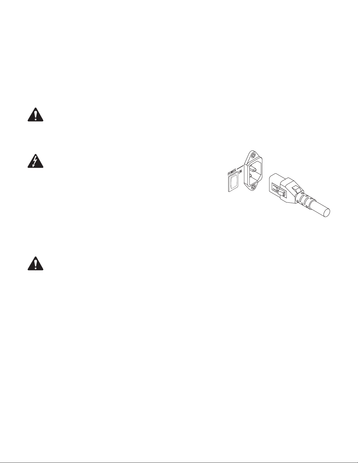
WARNING!:
dangerous voltage at the output terminals on the rear of the amplifi er. Use
caution not to touch these contacts. Turn off the AC Mains disconnect switch
prior to making any connections.
When the AC Power is on, there is a potential of having
The CXD4.3 and CXD4.5 amplifi ers have a Universal power supply 100 – 240 VAC, 50 – 60 Hz,
with an IEC locking connector. The CXD 4.2 has a Universal power supply 100 - 132/200-240
VAC, 50 – 60 Hz, with an IEC locking connector.
1. Make sure the power switch on the rear of the amplifi er is off.
2. Connect the IEC AC cable between the amplifi er rear AC connector and the AC source.
— Figure 3 —
AC Power
NOTE:
audio is present.
When you remove power from the amplifi er, then re-apply the power, the amplifi er returns to its last state.
If the amplifi er has no audio for fi fteen minutes, the amplifi er stops switching. The amplifi er returns to the Run mode the instant
TD-000367 -01 -B
6
Page 7
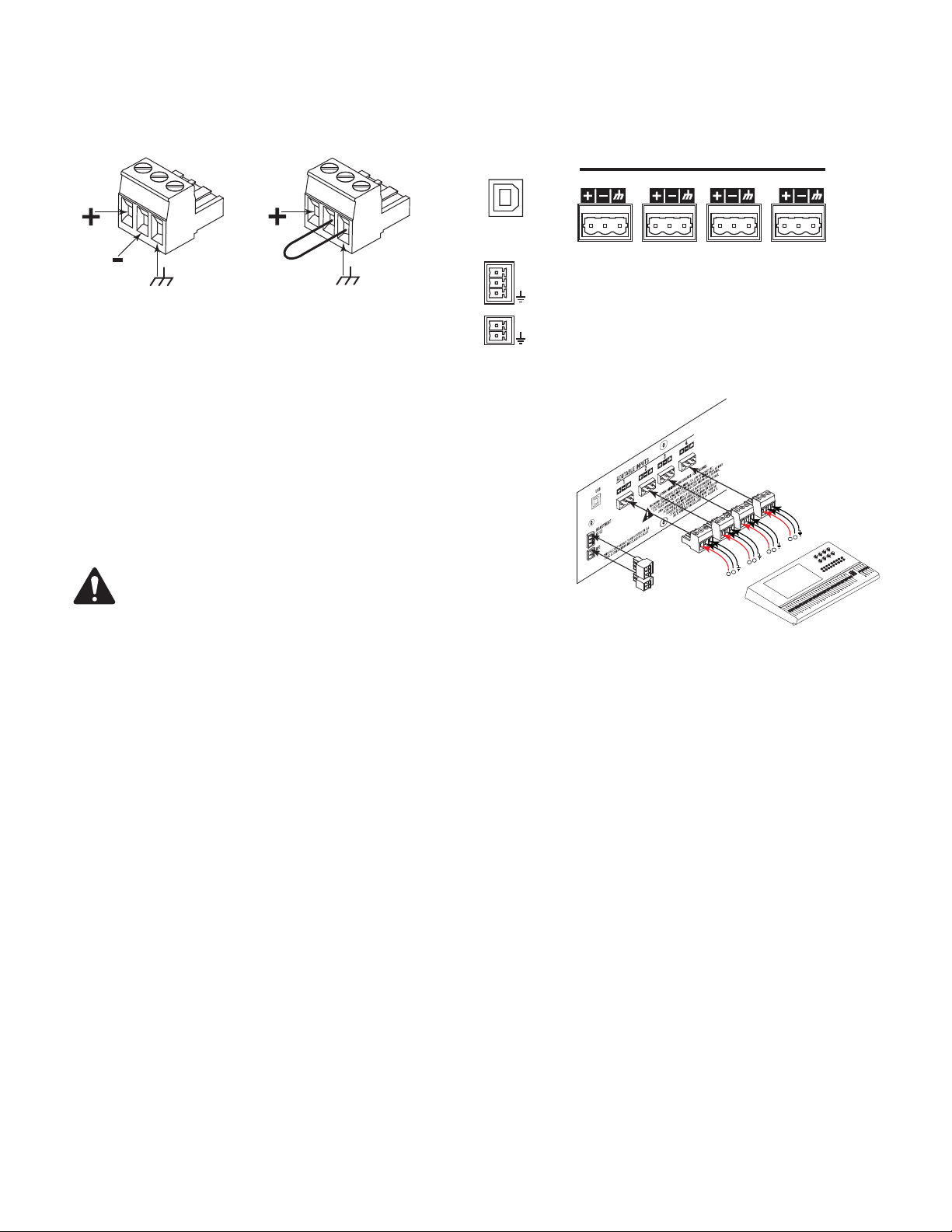
Inputs
Connect the Audio Inputs
Equilibrada
— Figure 4 —
No equilibrada
— Figure 5 —
USB
HEARTBEAT
GPO
GPI
ENTRADAS ENRUTABLES
2143
— Figure 6 —
There are four three-pin Euro-style connectors labeled 1 through 4 providing the audio
inputs on the CXD Amplifi ers. A single input can be mixed to one or a combination of
outputs. You can use from one to four of the inputs. The inputs are 10 kΩ balanced or
unbalanced, with a sensitivity of either +4 or +14 dBu.
1. Make sure your audio source devices are powered off.
2. Wire the audio line-level source to up to four Euro-style connectors (supplied). You
-
may use either balanced inputs (Figure 4) or unbalanced inputs (Figure 5).
NOTE:
The CXD Series has the capability of routing the inputs to different
outputs. Be sure that the connections you make here match the confi guration
of the amplifi er.
3. Plug the connectors into the appropriate receptacles (ROUTABLE INPUTS 1, 2, 3, 4)
Figure 6 and Figure 7.
-
+
— Figure 7 —
+
-
+
-
+
USB (Optional)
The USB cable (supplied) connects to a Mac or PC for use with the Amplifi er Navigator software. You can update the amplifi er fi rmware, save and
deploy confi guration fi les, and more. Refer to the Amplifi er Navigator online help for details.
GPIO/Heartbeat
There are two 3.5 mm Euro-style connectors on the rear of the amplifi er.
• Heartbeat — The heartbeat output supplies a square wave signal of 1 Hz @ 3.3 V. This signal can connect to a life-safety system to monitor the
go/no-go condition of the amplifi er. The amplifi er must be completely incapable of producing output for the heartbeat signal to stop. A missing
heartbeat alerts the life-safety system of the disabled condition. A user-initiated condition such as muting the outputs, placing the amplifi er in
Standby mode, or placing the amplifi er in Mute All mode, does not stop the heartbeat.
• GPO — The GPO can be triggered (High or Low fl ag) by one of the following faults:
◦ All Faults
◦ Thermal Limiting
◦ Impedance (selectable impedance boundaries)
• GPI — The GPI Input allows you to do one of the following from a remote location:
◦ Put the amplifi er into Standby or Run mode,
◦ Mute or unmute all outputs, or
◦ Recall one of two Presets
TD-000367 -01 -B
7
Page 8
Outputs
The CXD amplifi ers have four confi gurable outputs. You can set the power, combine outputs (bridged and parallel), and adjust the DSP for each
output. When the output confi guration of the amplifi er changes, the output terminals, controlled by relays, change accordingly. Use the diagrams
shown in
Select the Output Confi guration
The fi rst step in confi guring your amplifi er is to select a Preset based on the loudspeakers being connected to the amplifi er. The Preset Name is
representative of the confi guration. You can select a factory preset, and then adjust the parameters as needed, then save the confi guration as a userdefi ned preset. In addition, you can use the "Preset Wizard" on page 15 to create presets from one of the basic channel combinations. When the
confi guration is changed, all four channels are automatically muted.
Figure 9 thru Figure 17 as a reference for wiring the loudspeakers.
F1: A B C D
F7: ABC D
M
ABC
M
Current Preset Name
Selected Preset Name
Input Mixer
D
Frequency Range color
Output Confi guration
Input number
Sub-woofer
Low-Frequency
Mid Frequency
High-Frequency
Full Full Range
Frequency Range Color Codes
— Figure 8 —
WARNING!:
1. Turn the AC Mains power switch on the back of the amplifi er to on. The amplifi er starts in the Run mode.
the amplifi er. Use caution not to touch these contacts. Turn off the AC Mains disconnect switch prior to making any connections.
2. Press and release the front-panel power button. The button fl ashes red, the amplifi er is in Mute All mode.
3. Select the confi guration appropriate for your loudspeakers, using either Preset Recall, or the Preset Wizard.
When the AC Power is on, there is a potential of having dangerous voltage at the output terminals on the rear of
TD-000367 -01 -B
8
Page 9
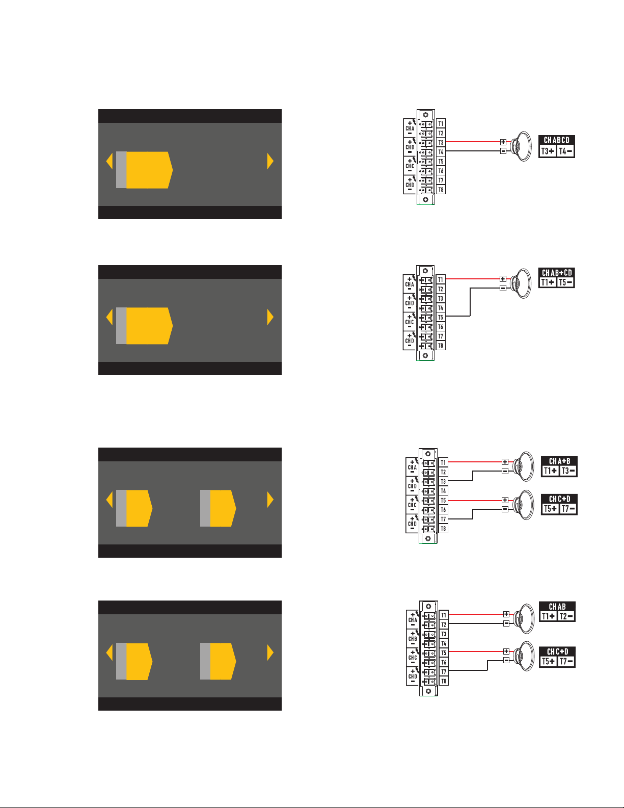
The following is a list of confi gurations for 1, 2, 3, and 4-channel outputs. This is not an exhaustive list, but is intended to give you an idea of what is
available and how the outputs would be wired.
One-Channel Confi gurations
F9: ABCD
F9: ABCD
M
ABCD
ABCD Parallel
— Figure 9 —
F8: AB+CD
F8: AB+CD
M
AB+CD
AB Parallel
Bridged with
CD Parallel
— Figure 10 —
Two-Channel Confi gurations
F6: A+B C+D
F6: A+B C+D
MM
A+B
C+D
A+B Bridged
C+D Bridged
TD-000367 -01 -B
F5: AB C+D
F5: AB C+D
MM
AB
C+D
— Figure 11 —
AB Parallel
C+D Bridged
— Figure 12 —
9
Page 10
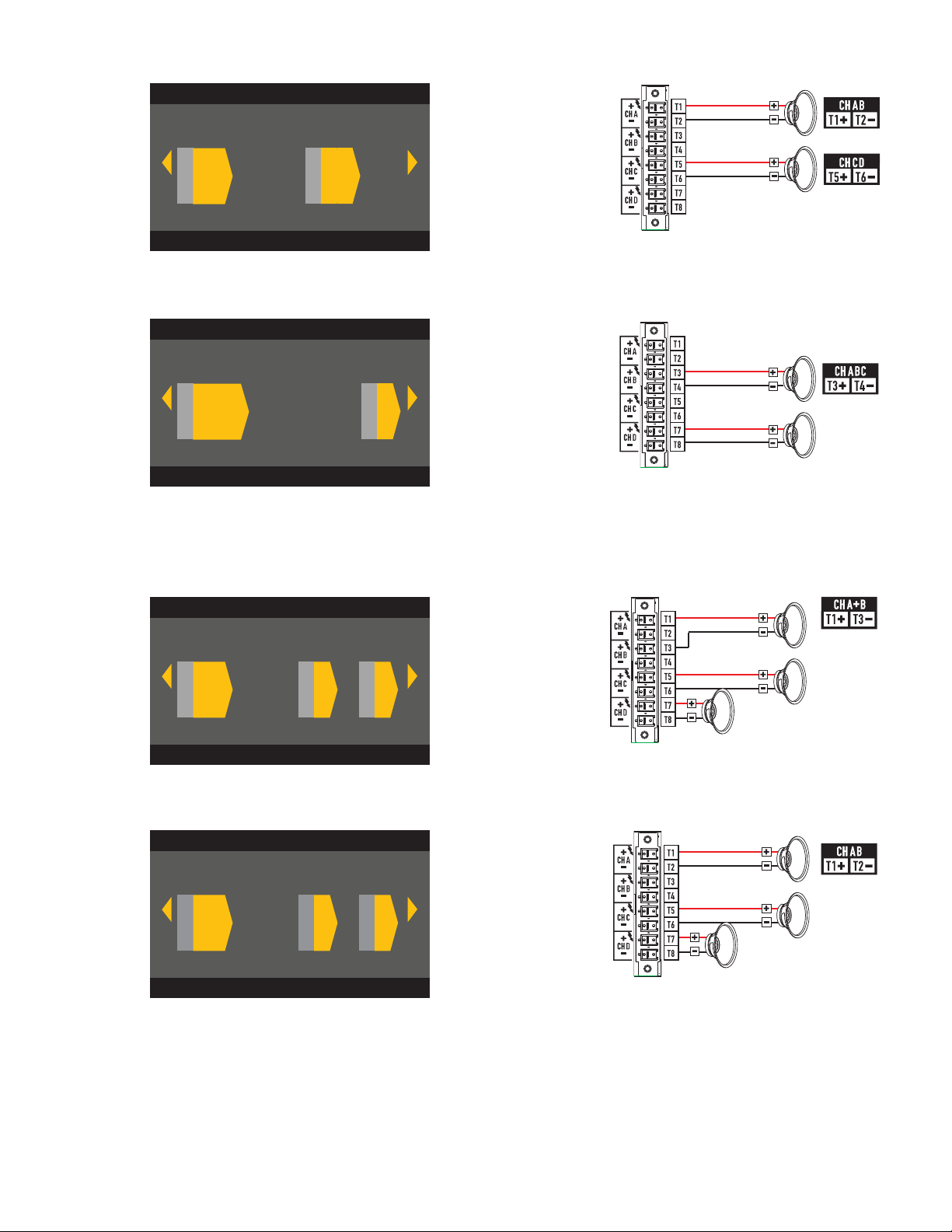
F4: AB CD
F4: AB CD
AB Parallel
CD Parallel
MM
AB
F7: ABC D
F7: ABC D
MM
ABC
CD
D
— Figure 13 —
ABC Parallel
D Single
— Figure 14 —
Three-Channel Confi gurations
F3: A+B C D
F3: A+B C D
A+B Bridged
C Single
D Single
MMM
A+B C D
— Figure 15 —
F2: AB C D
F2: AB C D
M
AB
M
M
C
D
— Figure 16 —
AB Parallel
C Single
D Single
TD-000367 -01 -B
10
Page 11

Four-Channel Confi guration
F1: A B C D
F1: A B C D
M M
ABMC
M
A Single
B Single
C Single
D
D Single
— Figure 17 —
Connect the Loudspeakers
WARNING!:
dangerous voltage at the output terminals on the rear of the amplifi er. Use
caution to not touch these contacts. Turn off the AC Mains disconnect switch
1. Turn the AC Mains power switch, on the back of the amplifi er, to OFF.
2. Connect the loudspeaker wiring to the 8-pin Euro-style connector. Refer to Figure 9
3. Install the Euro-style connector onto the rear of the amplifi er as shown in Figure 18.
4. Use a Phillips screwdriver to secure the connector.
prior to making any connections.
thru Figure 17.
When the AC Power is on, there is a potential of having
— Figure 18 —
TD-000367 -01 -B
11
Page 12

Amplifi er Control
A
(power
button)
MUTE
SEL
B
MUTE
SEL
1
2
OUTPUT
LIM
-10
-20
CLIP
SIG
INPUT
C
MUTE
SEL
3
D
MUTE
SEL
4
HOME
ENTER
EXIT
GAIN
MASTER
CONTROL
EXIT Button
EXIT
• Navigates out of the menu structure and parameter selection.
• In the edit mode, pressing EXIT reverts the value back to its prior
state, and exits the edit mode.
HOME Button
HOME
• If you are on the Home screen, pressing HOME displays the
alternate Home screen. Pressing HOME again returns you to the
primary Home screen.
• If you are on a navigation screen, pressing HOME takes you to the
home screen.
• If you are on an edit screen, pressing HOME will confi rm any value
being edited and take you to the Home screen.
— Figure 19 —
GAIN Button
GAIN GAIN
• Pressing the GAIN button from any screen takes
Off Mode
• Rear power switch is off, the amplifi er is not
operable. The power switch is the AC Mains
disconnect.
• The power button is not illuminated.
• Turn the power switch to on. The amplifi er enters the mode it was in
when power was removed. The power button is illuminated based on
the mode.
• GPI setup has an effect on the operation of the power button.
Run Mode
• From Standby or Mute All modes, press and release the
power button on the front panel.
• The power button is illuminated blue.
• The amplifi er is fully operable; audio can pass.
• GPI setup has an effect on the operation of the power button.
you to the output gain screen for the most recently accessed output
channel.
• Pressing GAIN again confi rms the gain change and returns to the
screen you were on when you pressed GAIN.
• The Gain button illuminates green when selected.
SEL Buttons
SEL SEL
• Use these buttons to navigate between input
channels or output channels. For example, if you are adjusting output
gain on channel A, pressing the channel B SEL button takes you to the
gain adjustment for channel B.
• These buttons change both Input and Output selection at the same
time. For example, if you select Output A then switch to an Input
screen, you are on Input 1.
• The SEL buttons are active on any Input or Output screen as indicated
by an illuminated SEL button, and a label in the upper right corner of
the screen (Input 1-4 or Output 1-4).
Standby Mode
• From Mute All or Run modes, press and hold the power
• The SEL buttons illuminate blue for output channels, and amber for
input channels.
button on the front panel for two to three seconds.
• The power button illuminates solid red.
MUTE Buttons
MUTE
• The front panel LCD is off.
• The amplifi er is not operable; audio will not pass.
• GPI setup has an effect on the operation of the power button.
• Use these buttons to mute the audio of the associated
output channel.
• When the output confi guration is changed, the MUTE buttons are
Mute All Mode
engaged automatically. You must manually unmute the channels.
• From the Run Mode, quickly press and release the power
button.
• The power button fl ashes red.
LIM LEDs
• Illuminates red when the Limiter is engaged.
LIM
• The outputs are muted and amplifi ers are off.
• The front panel and DSP functionality are fully operable. Any changes
you make are saved and take effect in the Run Mode.
• GPI setup has an effect on the operation of the power button.
-10 and -20 LEDs
• Indicates the dB below maximum output level of
the channel.
-10 & -20
Master Control Knob
• Scrolls up/down and right/left to select menu items and
parameters
• Adjusts parameters
ENTER Button
• Navigates into the menu structure
• Enters the edit mode for adjusting parameters
• Confi rms the changes you make, and exits the edit mode.
TD-000367 -01 -B
ENTER
CLIP LEDs
• Illuminates red when the input signal is being clipped.
SIG LEDs
• Illuminates blue when a signal greater than -40 dB is
present.
12
CLIP
SIG
Page 13

CXD Amplifi er Signal Flow
Input Settings Output Processing Amp Confi g.
Sensitivity
Switch
Sensitivity
Switch
Sensitivity
Switch
Sensitivity
Switch
A/D Meter Gain Mixer Mute
A/D Meter Gain Mixer Mute
A/D Meter Gain Mixer Mute
A/D Meter Gain Mixer Mute
Button
Activated
High-pass
High-pass
High-pass
High-pass
Filter
Filter
Filter
Filter
Gain /
Polarity
Gain /
Polarity
Gain /
Polarity
Gain /
Polarity
Crossover
Low-pass
Filter
Low-pass
Filter
Low-pass
Filter
Low-pass
Filter
5-Band
PEQ
5-Band
PEQ
5-Band
PEQ
5-Band
PEQ
Delay
Delay
Delay
Delay
RMS / Peak
Limiter
RMS / Peak
Limiter
RMS / Peak
Limiter
RMS / Peak
Limiter
D / A
D / A
D / A
D / A
A
B
D
E
Set by Preset or Wizard
Meter
Meter
Meter
Meter
— Figure 20 —
Menu Tree
Presets Inputs Outputs Utilities
Preset Recall Input Sensitivity Mixer w/Noise & Tone Status
Preset Save Input Gain Mode (Lo-Z, 70V, 100V) Amp ID
Preset Wizard Spkr Processing Display
Crossover Lockout
PEQ Password
Delay GPI
Limiter GPO
Array Correction*
Load Speaker
*For QSC Line Arrays only.
Save Speaker
AC Power On
After connecting the outputs to the loudspeakers, you may turn the amplifi er on.
1. Make sure the output gain settings for all audio-source devices (CD Players, Mixers, Instruments, etc.) are at the lowest output (max
attenuation).
2. Turn on all audio sources.
3. Turn the AC Mains power switch on the back of the amplifi er to ON. The amplifi er starts in the state it was in when power was removed. If
the amplifi er is in Standby or Mute All mode (Power button LED solid red or blinking), press the Power button to change the amplifi er to Run
mode.
4. You can now bring up the outputs of your audio sources.
TD-000367 -01 -B
13
Page 14

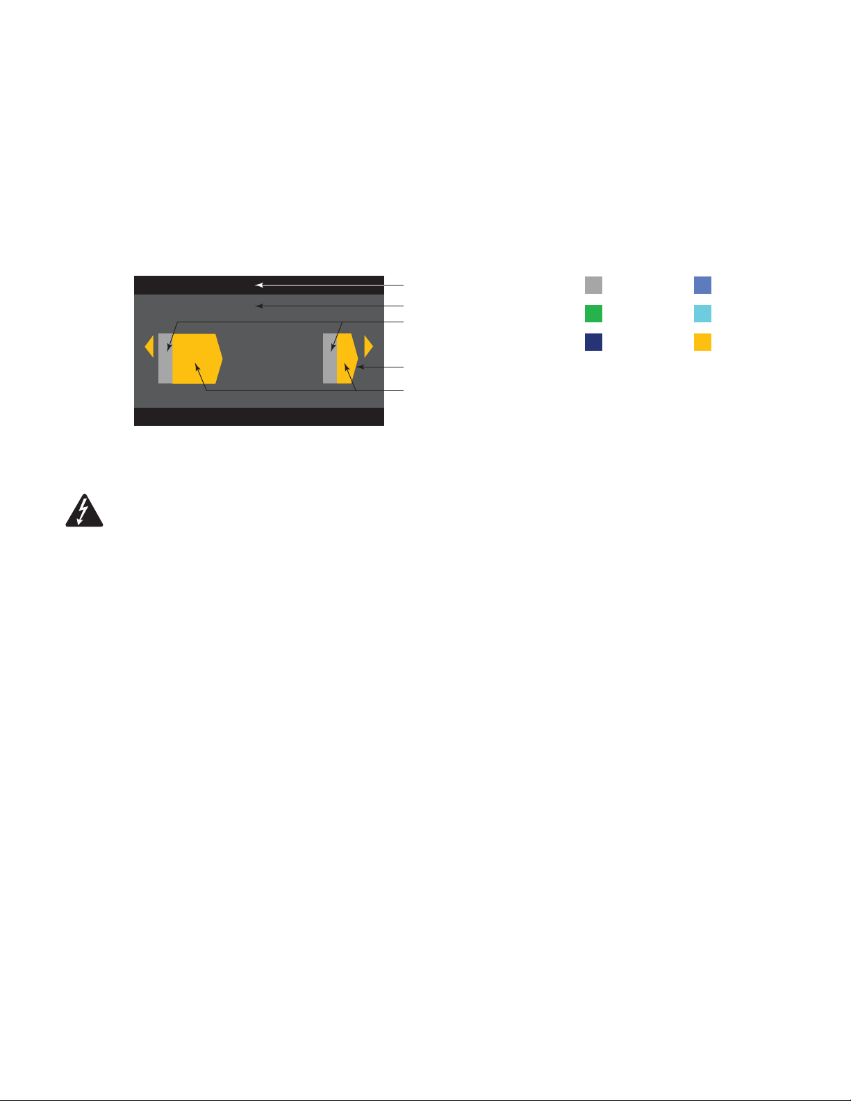
Screen Types
Informational
Informational screens, like the HOME screen, are
designed to provide you with a good amount of
useful information at a glance.
F1: A B C D
Home (Press HOME for more information)
Full
A - FR
+1.5 dB
Amp Status:
Full
B - FR
+3.5 dB
121 V 7.2 AAC Voltage: AC Current:
OK
Full
C - FR
+1.5 dB
Full
D - FR
+1.5 dB
Preset # and Name
Location and breadcrumbs
Channel Confi guration
and Gain
AC Voltage and Current
Amplifi er Status
— Figure 21 —
Navigational
Navigational screens provide the means to move
around and select menu items. Use the Master
Control knob, ENTER and EXIT buttons for navigation.
This is an example of one type of navigational screen,
there are others.
Parameter Editing
Parameter editing screens allow you to select, edit,
and confi rm changes for various system parameters.
Use the ENTER button to edit and confi rm changes
to parameters. Use the Master Control knob to select
parameter, and make adjustments. Use the EXIT
button to exit the edit mode without saving changes.
F1: A B C D
Menu
PRESETS
Preset Recall and Save
INPUTS
— Figure 22 —
F1: A B C D
Gn/Pol
Gain
-7.0 dB
Polarity
POL+
Output
A
20 dB
-60 dB
Preset # and Name
Location and breadcrumbs
Empty area indicates no
selections above
Current Menu Selection
Next Menu selection below (CW)
Parameter being edited
Parameter not selected
Parameter selected
Gain
-7.0 dB
— Figure 23 —
About Presets
The CXD amplifi ers are preset driven. An understanding of how presets work is essential to get the most out of the amplifi ers. A Preset, in the context
of the CXD amplifi ers, is a combination of amplifi er confi guration (inputs and outputs), DSP, and loudspeaker assignments. When a preset is recalled it
can change the output routing and any of the DSP settings.
The CXD amplifi ers come with 20 unchangeable factory presets, and 50 user-defi ned presets. The factory presets are designed to be starting points
for creating the presets you need for your particular installation. Factory presets F1: thru F9: have no DSP or loudspeaker assignments, only output
confi gurations. Factory presets F10: thru F20: include basic settings along with the output confi gurations.
User-defi ned Presets
Presets U1 through U50 are all confi gured from the factory the same as factory preset F1. Anytime you save a preset, it overwrites one of the
User-defi ned Presets. There are three ways of creating user-defi ned presets.
• You can recall a user-defi ned preset with the output confi guration you want, then modify the DSP parameters and SAVE it by overwriting the one
you recalled, or you can SAVE AS (overwrite) another user-defi ned preset.
• You can recall a factory preset, modify the parameters, then SAVE AS one of the user-defi ned presets. The SAVE procedure is not available for
factory presets.
• You can use the Preset Wizard to set the output confi guration, power output, and other parameters, then SAVE AS (overwrite) a userdefi ned preset.
TD-000367 -01 -B
14
Page 15

Preset Wizard
The Preset Wizard simplifi es the preset creation process, and allows you to create a preset from the ground up. The Preset Wizard provides a
mechanism for you to select the desired power and load. Based on these selections, the best amplifi er confi guration is selected and you are then
allowed to select and assign loudspeakers to each output.
NOTE:
The power levels shown in this procedure are taken from the CXD4.3 unless indicated otherwise. CXD4.2 will show less power
and CXD4.5 will show greater power. For complete details refer to the "Specifi cations" on page 31.
HOME > PRESETS > PRESET WIZARD (ENTER)
Step 1 —
About the Preset Wizard
ABOUT SPEAKERS SAVE
Preset Wizard does the following :
• Configures the amplifier
• Loads DSP settings for assigned speakers
Tips:
• Start with the highest power
• Speakers do not need to be assigned
to each output
NEXT
Preset Wizard does the following:
• Confi gures the amplifi er
• Loads DSP settings for
assigned speakers
Tips:
• Start with the highest power
• Speakers do not need to be
assigned to each output
To Continue, press
ENTER
HOME > PRESETS > PRESET WIZARD > ENTER (ENTER)
Step 2 —
Adjust Impedance and Power
OUTPUTS SPEAKERS SAVE
Output:
Imped:
Power:
Remaining Power Available: 1875 W
Enter Load Profile (Impedance and Power)
AB C D
8.0 - - - - - -
625 - - - - - -
Adjust Impedance based on the total
loudspeaker load connected to the
channel.
Default = 8
Default = min. for amp
Impedance and Power are dynamically
linked for adjustments.
Scroll to select (Impedance or Power)
To edit, press
Turn to adjust parameter
To confi rm, press
Repeat for remaining output channels
ENTER
ENTER
Possible Output Mode Combinations using the Preset Wizard
B
A
- - -
- - -
25%
25%
*
C
- - -
25%
D
- - -
25%
AB
- - -
50%
C
- - -
25%
D
- - -
25%
Modes: A B = Separate Channels / A+B = Bridge Mode / AB = Parallel Mode
* Percentages are used to represent the power for different amplifi er models.
Step 3 —
Select Output Channel for Speaker Assignment
OUTPUTS SPEAKERS SAVE
Output:
Imped:
Power:
Spkr:
ADCB
8.0 8.08.08.0
625 625625625
- - - - - - - -- - - -- - - -
Assign
Assign
AB
- - -
50%
AssignAssign
CD
50%
A+B
C
- - -
- - -
50%
— Figure 24 —
When you are fi nished setting the
Impedance and Power for each
output, continue to scroll to access
the SPEAKERS tab.
Loudspeaker assignment is optional,
you can assign a loudspeaker to one
or more channels, or none at all.
- - -
25%
- - -
25%
D
A+B
C+D
- - -
- - -
50%
50%
ABC
- - -
75%
D
- - -
25%
AB + CD
- - -
100%
ABCD
- - -
100%
Scroll to select the Output channel.
To Assign a loudspeaker, press
ENTER
Continue to the next Step.
TD-000367 -01 -B
15
Page 16

Step 4 —
Select Speaker Type for Channel
OUTPUTS SPEAKERS SAVE
A
Speaker:
Band:
Filter:
Output:
QSC AP-5152
Full Range
Default
ASSIGN
Band and Filter selections
are based on the Speaker
you select. You must select a
loudspeaker before selecting
Band and Filter.
When you have fi nished
assigning loudspeakers,
continue to scroll to access the
SAVE tab.
To edit Speaker, press
Scroll to select a Speaker model
To confi rm, press
Scroll to select (Band, Filter)
To edit, press
Turn to adjust parameter
ENTER
ENTER
ENTER
To confi rm, press
ENTER
Scroll to select ASSIGN
To assign the speaker to the output channel, press
Step 5 —
Select User Preset Number
OUTPUTS SPEAKERS SAVE
User Preset Number:
New Preset Name
Con f i g - A
SAVE
Edit preset number or press EXIT
21
Scroll to the Save screen
To edit User Preset number, press
Turn to adjust parameter
To confi rm, press
Scroll to the New Preset Name
ENTER
ENTER
ENTER
Step 6 —
Assign New User Preset Name
SPEAKERSABOUT
User Preset Number:
New Preset Name
My S pk r
SAVE
Press ENTER to edit name
SAVE
21
Indicates editing
Indicates “Speaker
Preset Name”
is selected
Up to 21 characters
A - Z / a - z / 0 - 9 /
_ / - / space
To add Speaker Profi le Name, press
Scroll to desired letter position press
Turn to select desired character press
When fi nished with lettering, press twice
EXIT
When fi nished, scroll to SAVE press
To RECALL Preset, press
ENTER
ENTER
ENTER
ENTER
ENTER
TD-000367 -01 -B
16
To not RECALL Preset, press
EXIT
Page 17

Modify Presets
To modify a preset, recall the preset with the desired output confi guration, modify the Input parameters, Output parameters, then save the preset. In
addition, you can save the preset as you are going thru the creation process.
Recall a Preset
A Preset includes the output confi guration, input parameters, and loudspeaker profi les (DSP, load, and assignments). There are 20 factory presets that
can be recalled, but not overwritten, and 50 user-defi ned presets that can be recalled and overwritten.
• Factory presets F1: Confi g thru F9: Confi g contain output confi gurations only.
• Factory presets F10: thru F20: contain the output confi gurations and basic DSP for the confi gurations.
• There are 50 user presets that can be recalled and overwritten.
Recalling a Preset changes the confi guration of the amplifi er. You can recall factory or user-defi ned presets.
HOME > PRESETS > PRESET RECALL (ENTER)
Step 1 —
Select Preset
F1: A B C D
F1: A B C D
MMMM
A B C D
Scroll to desired Preset
20 Factory, 50 User-defi ned
Indicates more Presets
Input Sub MF FullHFLF
Step 2 —
Confi rm Selection
F1: A B C D
F18: 3-Way
To select the Preset confi guration, press
To confi rm the selection, press
ENTER
ENTER
MMM
A+B
Press ENTER to confirm selection
C D
The message at the bottom changes to: "Recalling Preset now..."
You may hear relays clicking!
TD-000367 -01 -B
17
Page 18

Set up the Inputs
NOTE:
Changes made to input levels are in real time.
HOME > INPUTS > SENS (ENTER)
Step 1 —
Select Input Sensitivity
F1: A B C D
Input
Const
Sens
Sens
+4 dBu
Input
1
Gain (dB)
0.0
After confi rming the Sensitivity
setting, you can scroll to Gain
and adjust it, before moving to
the next Input.
Constant Sensitivity gives you
maximum power out when the
input device's output reaches
the Sensitivity you set.
+4 dBu = 70V into 8Ω
+14 dBu = 100V into 8Ω
Scroll to select (+14 or +4 dBu)
To confi rm selection, press
To move to the next input, press
Repeat this procedure for
remaining input channels
ENTER
SEL
If sensitivity setting is +4 dBu, a 4 dBu signal from the input device results in 100V (CXD4.5) and 70V (CXD4.3) at the output of amplifi er. So amplifi er
gain, at +4 dBu sensitivity, is 38.5 dB (CXD4.5) and 35.5 dB (CXD4.3). Input signal will clip 10 dB above sensitivity setting.
If sensitivity setting is +14 dBu, a 14 dBu signal from the input device results in 100V (CXD4.5) and 70V (CXD4.3) at the output of the amplifi er. So amp
gain at 14 dBu sensitivity is 28 dB (CXD4.5) and 25 dB (CXD4.3). Input signal will clip 10 dB above sensitivity setting.
HOME > INPUTS > INPUT GAIN (ENTER)
Step 2 —
Set Input Gain
F1: A B C D
Input
1
Scroll to select (-100 thru 20 dB)
To confi rm selection, press
To move to the next input, press
Repeat this procedure for
ENTER
SEL
remaining input channels
Input
Const
Sens
Sens
+4 dBu
Set up the Outputs
NOTE:
Mixer
The CXD amplifi ers are equipped with an internal mixer that allows you to
adjust the signals from each input to each of the four outputs. Figure 25 is a
diagram of the Mixer for Output Channel A.
• The default setting for the Input Gain is 0.0 dB, and is set in the
INPUTS section.
• Each output channel has four inputs, each controlled by a Mixer Gain.
• The Input Gain and Mixer Gain are cumulative. For example, if you set the
Input Gain to +2.0 dB, and the Mixer Gain to -5.0 dB, the resulting output
is -3.0 dB
As a default channel "1" is mixed to output A, 2 to B, 3 to C, and 4 to D, all
other input channels are set to -100. Adjusting an Input Gain changes that
channel's input to the mixers of all channels. Changing a Mixer Gain affects only
that input for the selected output channel.
Changes made to outputs are in real time.
Gain (dB)
0.0
INPUTS OUTPUT
MIXER A
Input 1
Input 2
Input 3
Input 4
0.0 dB
0.0 dB
0.0 dB
0.0 dB
Output Mixers
Output Mixers
Output Mixers
Output Mixers
0.0 dB
B
C
D
-100 dB
B
C
D
-100 dB
B
C
D
-100 dB
B
C
D
— Figure 25 —
Output
A
TD-000367 -01 -B
18
Page 19

HOME > OUTPUTS > MIXER (ENTER)
Step 1 —
Set Mixer Gains
F1: A B C D
Output
A
Scroll to the Input you wish to adjust
To edit, press
ENTER
Adjust the Gain for the selected input
ENTER
SEL
EXIT
MIXER
Input 1
4.2
Input 2
-100.0
Input 3
-49.9
Input 4
-100.0
To confi rm, press
Repeat for the remaining inputs
To move to the next Output, press
When you are fi nished, press
HOME > OUTPUTS > MIXER (ENTER)
Step 1 —
Test - Pink Noise and Tone Generator
MIXER
F1: A B C D
TEST
Source
Ton e
Noise
OFF
Ton eONFreq
Output
A
PINK
20.0 Hz –20 kHz
Output Levels
Off (-80 dB) to -10 dB
1.0k
• You must be in the TEST mode to use Noise and Tone
• Noise and Tone cannot be used on the same channel at the same time.
• Use the Source to switch between Noise and Tone.
• Noise and Tone do not go through the Mixer.
• Noise and Tone Gain controls are independent of the Input and Output
Scroll to TEST press
On Source, press
Select Tone or Noise press
Scroll to Noise press
Adjust Noise to desired level press
Scroll to Tone press
Adjust Tone to desired level press
Scroll to Freq press
Adjust to desired frequency press
When you are fi nished, press
ENTER
ENTER
ENTER
ENTER
ENTER
ENTER
ENTER
ENTER
ENTER
ENTER
Gain controls.
Mode Select
HOME > OUTPUTS > MODE (ENTER)
Step 1 —
TD-000367 -01 -B
Select the Output Mode
F1: A B C D
Outputs > Mode
MODE SELECT
Low-Z, 70V, 100V
Output
Mode:
Low-Z
Press ENTER to confirm
Scroll to select Low-Z, 100V, or 70V
A
The CXD4.3 and CXD4.5 provide 70V and 100V direct
drive for each output. The CXD4.2 offers 70V and 100V
direct drive when two output channels are bridged.
19
To confi rm, press
ENTER
Page 20

Loudspeaker Processing
The Speaker Processing section allows you to make adjustments to the Crossover, EQ, Delay, Limiter, and QSC Array details for each output channel.
In addition, you can load a pre-defi ned loudspeaker then make any adjustments needed, and save the changes as a user-defi ned loudspeaker.
Depending on the loudspeaker selection, various parameters are not available for adjustment. When you make adjustments, you are making them in
real time. If audio is passed while making changes, it is affected by the change.
The following instructions are not all in menu order, and all are optional. Repeat the following procedure for each output channel as necessary.
Load Speaker Profi le
HOME > OUTPUTS > SPKR PROC > LOAD SPKR (ENTER)
A loudspeaker profi le includes all the DSP and loudspeaker characteristics available in the SPKR PROC section. When you LOAD a loudspeaker, you
are loading all of the DSP and characteristics of that loudspeaker. You can start by loading a loudspeaker and then make modifi cations and save your
new profi le, or you can build the profi le without loading a loudspeaker, and then save it as a new profi le. If you load a QSC loudspeaker, the amplifi er
is set for that specifi c loudspeaker and some parameters may be locked out because they are set to their optimal value by the Intrinsic Correction
Calculator, and should not be adjusted. The CXD comes with a number of supported loudspeakers from other manufacturers. Refer to the list under
"Supported Loudspeakers" on page 30. There may be additions to this list in the future that can be loaded with fi rmware updates.
NOTE:
Step 1 —
you made are overwritten.
Load Speaker About
If you make changes to any of the loudspeaker processing parameters, and then LOAD a loudspeaker profi le, all the changes
SPEAKERS LOADABOUT
This function will load a speaker from the
database to this output channel; it loads
all of the speaker tuning parameters into the
outprocessing.
NEXT
This function will load a speaker from the
database to this output channel; it loads all
of the speaker tuning parameters into the
out-processing.
To continue, press
ENTER
Step 2 —
Load an Existing Loudspeaker for the Selected Output
ABOUT SPEAKERS LOAD
A
Speaker:
Band:
Filter:
Output:
QSC AP-5152
Fullrange
Default
LOAD
Band and Filter selections
are displayed and
constrained based on the
loudspeaker.
To edit Speaker, press
Scroll to select Speaker model
To confi rm, press
Scroll to (Band, Filter)
To adjust, press
Adjust selected parameter
ENTER
ENTER
ENTER
TD-000367 -01 -B
20
To confi rm, press
Scroll to LOAD
To Load the speaker profi le to the selected output, press
ENTER
ENTER
Page 21

Crossover
HOME > OUTPUTS > SPKR PROC > CROSSOVER > HIGH-PASS (or LOW-PASS) (ENTER)
NOTE:
If you select a QSC Loudspeaker, you will see that the high-pass, or low-pass fi lters are LOCKED. QSC has given these
loudspeakers specifi c voicings tailored for that loudspeaker that should not be changed. If there is any crossover adjustments applied in
these voicings, you will be able to see the applied crossover on the graphs of the Crossover screens.
Step 1 —
HOME > OUTPUTS > SPKR PROC > CROSSOVER > GAIN/POL > GAIN (ENTER)
Step 2 —
Set the Crossover High- and/or Low-pass fi lters
F1: A B C D
HPF
Freq
70.0
Typ e
BWrth
Output
A
20 dB
-60 dB
Slope
24dB/oct
Set the Crossover Gain and Polarity
F1: A B C D
Gn/Pol
Gain
-5.5 dB
Polarity
POL +
Output
A
20 dB
-60 dB
Freq: 20 - 20 kHz
Type:
• Butterworth
• Linkwitz-Riley,
• Bessel-Thomson
Slope:
6dB to 48dB/oct depending
on Type
+
Gain –100 to +20 dB
–
Polarity + or –
Scroll to select (Freq, Type, Slope)
To edit, press
Turn to adjust parameter
To confi rm, press
To exit, press
Scroll to select (Gain or Polarity)
To edit, press
Turn to adjust parameter
To confi rm, press
To exit, press
ENTER
ENTER
EXIT
ENTER
ENTER
EXIT
EQ
HOME > OUTPUTS > SPKR PROC > EQ > BAND 1, 2, 3, 4, or 5 (ENTER)
The graph is a composite of all fi ve bands. Each band has a full range of 20 Hz to 20 kHz.
Step 1 —
Set the EQ
F1: A B C D
Band 1
Typ e
Parametrc
Gain
-35 dB
Output
A
20 dB
-60 dB
Freq
100BW.01
Type: Bypass, Parametric, Low Shelf,
High Shelf (Default Bypass)
Gain: -40 to +20 dB (Default 0.00)
Freq: 20 to 20kHz (Band 1 Def 100 Hz)
(Band 2 Def 500 Hz)
(Band 3 Def 1 kHz)
(Band 4 Def 2.5 kHz)
(Band 5 Def 5 kHz)
BW: 0.01 to 3.00 Octive
(Default 1.00 Oct.)
Scroll to select
(Type, Gain, Freq, BW)
To edit, press
Turn to adjust parameter
To confi rm, press
To exit, press
ENTER
ENTER
EXIT
TD-000367 -01 -B
21
Page 22

Delay
HOME > OUTPUTS > SPKR PROC > DELAY (ENTER)
Distance measurements are based on the speed of sound being 340 meters/second, or 2.94 milliseconds/meter.
Step 1 —
Set the Output Delay Time
F1: A B C D
Outputs > Spkr Proc > Delay
Distance
3.4 meters
11.3 feet
Delay
State
Bypass
Time (ms)
10.0
Output
A
Delay:
0.0 ms to
75.00 ms
0.021 to 1.0 ms increments
State:
Bypass or
On
Scroll to (Delay Time or Bypass)
To edit, press
Turn to adjust parameter
To confi rm, press
To exit, press
ENTER
ENTER
EXIT
Limiter
NOTE:
If you select a QSC Loudspeaker, you will see that the limiter is LOCKED. QSC has given these loudspeakers specifi c limiter
settings tailored for that loudspeaker that should not be changed. If there is a limiter applied in these voicings, you will be able to see the
HOME > OUTPUTS > SPKR PROC > LIMITER
Step 1 —
applied limiter on the graph.
Gain Reduction
F1: A B C D
Outputs
DELAY
LIMITER
Limiter Params
ARRAY
Gain Reduction
0.0 dB
Press Enter to Edit
XO EQ DL LM ACLM
Output
A
The Gain Reduction currently
being applied to the selected
Output channel.
To edit the Limiter settings, press
ENTER
Step 2 —
Set the Limiter Mode
TD-000367 -01 -B
F1: A B C D
AUTO
Typ e
Med
SpkrPwr
200W
Output
A
SpkrImp
8.0
22
To edit the Limiter mode, press
Turn to select the mode for the Limiter
AUTO
ADV
OFF
To confi rm setting, press
ENTER
ENTER
Page 23

Set AUTO Mode Parameters
NOTE:
SpkrPwr maximum output depends on the amplifi er and the output confi guration you select. The maximum for separate
channels is 1250 W, a single combined channel (ABCD or AB+CD) can be up to 5000 W depending on the amplifi er.
HOME > OUTPUTS > SPKR PROC > LIMITER > AUTO
Step 1 —
Set the AUTO Mode Parameters
F1: A B C D
AUTO
Typ e
Med
SpkrPwr
200W
Output
A
SpkrImp
8.0
Type:
Aggressive
Medium
Mild
SpkrPwr:
10.0 W to 1250 KW
SpkrImpd:
2.0 to 16.0
Scroll to select (Type, SpkrPwr, SpkrImp)
To edit, press
Turn to adjust parameter
To confi rm, press
To exit, press
ENTER
ENTER
EXIT
Type
- the Auto Limiter Type is a protection level and its values are, Mild, Medium and Aggressive. This Type parameter, along with the Power Rating
and Impedance drive an algorithm designed to maximize the performance of your loudspeakers. They set the RMS and Peak threshold values as well
as their attack and release setting.
SpkrPwr
- if a single speaker is being driven, the SpkrPwr should be the continuous power rating of that loudspeaker. If multiple speakers are being
driven this value should be the combined power rating for the load.
SpkrImp
- if a single speaker is being driven, the SpkrImp should be the nominal impedance of that loudspeaker. If multiple speakers are being
driven this value should be the combined impedance for the load.
Set Advanced Mode Parameters
NOTE:
If you select a QSC Loudspeaker, you will see that the limiter is LOCKED. QSC has given these loudspeakers specifi c limiter
settings tailored for that loudspeaker that should not be changed. If there is a limiter applied in these voicings, you will be able to see
the applied limiter on the graph. The limiter is also locked if the 70V or 100V mode is selected.
HOME > OUTPUTS > SPKR PROC > LIMITER > ADV
Step 2 —
Set the ADV Mode Parameters
F1: A B C D
ADV
RMSThr
100.0V
PkThr
155.0V
Output
A
RMSThr: 3.0V to 100.0V
PkThr: 5.0V to 155.0V
PkAttk: 0.10 ms to 20.0 ms
PkRel: 1.00 ms to 1.0 s
RMSAttk: 0.05 s to 10.0 s
RMSRel: 1.0 s to 60.0 s
Thr = Threshold, Pk = Peak, Attk = Attack, Rel = Release
Scroll to select (RMSThr, PkThr,
PkAttk, PkRel, RMSAttk, & RMSRel)
To edit, press
Turn to adjust parameter
To confi rm, press
To exit, press
ENTER
ENTER
EXIT
TD-000367 -01 -B
23
Page 24

Array Correction
HOME > OUTPUTS > SPKR PROC > ARRAY (ENTER)
Step 1 —
NOTE:
Set Splay Angle and Number of Boxes in the Array
You must have a QSC line array loaded in order to access the Array Correction parameters.
F1: A B C D
AC
Output
Splay Angle: Total cumlative
angle of the array.
Array Length: Total number of
boxes in the array.
Angle
15.0
Boxes #
4
A
Angle:
0.0° to 90.0°
Boxes #:
0 to 24
Scroll to select (Angle or Boxes#)
To edit, press
Turn to adjust parameter
To confi rm, press
To exit, press
ENTER
ENTER
EXIT
Save a Loudspeaker
When you Save a speaker profi le, you are saving all of the Output settings currently active for the channel. The new profi le you save does not need to
be Loaded, it is already active.
HOME > OUTPUTS > SPKR PROC > SAVE SPKR (ENTER)
Step 1 —
Save Loudspeaker About
SPEAKERSABOUT SAVE
This function is provided to enable saving a
speaker to the database.
BEFORE saving a speaker, enter the desired
speaker tuning parameters (Gain, Crossover,
EQ, Delay, and Limiter). THEN save the
speaker to the database.
NEXT
This function is provided to enable saving a
speaker to the database.
BEFORE saving a speaker, enter the desired
speaker tuning parameters (Gain, Crossover,
EQ, Delay, and Limiter). THEN save the speaker
to the database.
To continue, press
ENTER
Step 2 —
Step 3 —
Save a Loudspeaker with Custom Load Profi le
ABOUT SPEAKERS SAVE
Output Data:
Band: 2-Way LF
Power Rating:
Enter Speaker Info
AB + CD
16.0Nominal Imped:
1000
Name the Loudspeaker Profi le
SPEAKERSABOUT
Speaker Profile Name
My S pk r
SAVE
SAVE
Press ENTER to edit name
Nominal Impedance
and Power Rating are
the nominal settings for
a single loudspeaker of
this type.
Indicates editing
Indicates "Speaker
Profi le Name"
is selected.
Up to 21 characters
A - Z / a - z / 0 - 9 /
_ / - / space
Scroll to select (Band,
Nominal Imped, Power Rating)
To edit, press
Turn to adjust parameter
To confi rm, press
After confi rming settings, Scroll to SAVE
To add Speaker Profi le Name, press
Scroll to desired letter position press
Turn to select desired character press
When fi nished lettering, press twice
EXIT
Scroll to SAVE press
ENTER
ENTER
ENTER
ENTER
ENTER
ENTER
TD-000367 -01 -B
24
Page 25

Save a Preset
After modifying the Inputs and Outputs for all channels, save the current settings as one of the 50 user-defi ned presets (U1: thru U50:). Each of the
user presets, by default, is the same as factory preset F1: A B C D, so when you save the preset you are "overwriting" the preset currently in that
numbered position. If you started by recalling a factory preset, you must use the SAVE AS feature. If you started with a user-defi ned preset, you can
overwrite the preset you started with using the SAVE feature, or use the SAVE AS feature to overwrite a different user preset.
SAVE AS
HOME > PRESETS > PRESET SAVE> PRESET SAVE AS > (ENTER)
Step 1 —
Save a New Preset - Select and Edit Preset Number
U1: A B C D
User Preset Number:
New Preset Name
Con f i g - A
21
Current active
preset.
To edit User Preset number, press
Turn to select desired number (1 thru 50)
To confi rm User Preset Number, press
ENTER
ENTER
SAVE
Edit preset number or press EXIT
Step 2 —
Name the Preset
U1: A B C D
User Preset Number:
New Preset Name
Con f i g X A
Press ENTER to edit preset name
SAVE
21
Indicates editing
Indicates "Speaker
Profi le Name"
is selected.
Up to 21 characters
A - Z / a - z / 0 - 9 /
_ / - / space
Scroll to New Preset Name press
Scroll to desired letter position press
Turn to select desired character press
ENTER
ENTER
ENTER
Step 3 —
Save Preset
U1: A B C D
Con f i g X A
Press ENTER to save preset
User Preset Number:
New Preset Name
SAVE
21
When the Preset is
saved, it becomes the
active preset.
When you are fi nished naming, press
Scroll to SAVE
Press
To confi rm SAVE, press
EXIT
ENTER
ENTER
TD-000367 -01 -B
25
Page 26

SAVE
Use this SAVE procedure when you are saving the preset by overwriting the currently active user preset. After you use the SAVE AS feature to save the
preset you are working on, it then becomes the currently active preset, and you can use the SAVE feature to save as you work on the preset.
HOME > PRESETS > PRESET SAVE > SAVE (ENTER)
Step 1 —
Overwrite Preset
U1: A B C D
To save, press
To exit without saving, press
ENTER
EXIT
SAVE
To confi rm Save, press
Press ENTER to save preset
ENTER
Utilities
The Utilities section provides the following amplifi er information and functionality:
Amplifi er Health
HOME > UTILITIES > STATUS (ENTER)
Step 1 —
Check the Amplifi er's Health
UTILITY - STATUS
Amp Total Run Time: 22:37:48 Hrs
Hardware: V12
Firmware: V1.0.22
DC Status: OK
VRail 1: 148V
VRail 2: -150V
Temperature:
CH1 & CH3: 27C
CH2 & CH3: 29C
Power Supply: 24C
Amp Total Run Time:
HH:MM:SS
Hardware version
Firmware version
update thru Amplifi er Navigator
DC Status:
VRail 1 = +147VDC +/- 5V typical
VRail 2 = -147VDC +/- 5V typical
Temperature (CXD 4.3 & 4.5)
Thermal Limiting starts at 69ºC
Thermal Shutdown at 80ºC
Name the Amplifi er
HOME > UTILITIES > AMP ID (ENTER)
Step 1 —
TD-000367 -01 -B
Name the Amplifi er
UTILITY - AMP ID
Serial #: 123abc Amp ID: my amp ID
Change Amp ID to:
my amp I D
CONFIRM
Indicates editing
Indicates "New
Preset Name"
is selected.
Up to 21 characters
A - Z / a - z / 0 - 9 /
_ / - / space
26
To edit "Change Amp ID to:" press
Scroll to desired letter position press
Turn to select desired character press
When you are fi nished, press
Scroll to CONFIRM press
ENTER
ENTER
ENTER
ENTER
ENTER
Page 27

Setup the Display
HOME > UTILITIES > DISPLAY (ENTER)
Step 1 —
Display
UTILITY - DISPLAY
DISPLAY TIMEOUT NEVER
TIMEOUT FUNCITON
Blackout
Scroll to desired DISPLAY TIMEOUT press
Scroll to TIMEOUT FUNCTION press
Turn to desired FUNCTION press
Scroll to CONFIRM press
ENTER
ENTER
ENTER
ENTER
CONFIRM
DISPLAY TIMEOUT
The HOME, ENTER, EXIT, GAIN, and the MASTER CONTROL exit Demo or Blackout
mode. The power, MUTE and SEL buttons are still functional, in addition to exiting
the Demo or Blackout mode.
Password (Security)
HOME > UTILITIES > PASSWORD (ENTER)
Step 1 —
Add or Change the Password
UTILITY - CHANGE PASSWORD
Current Password:
QSC
New Password:
MY pa s wosr
CONFIRM
The default password for all amplifi ers is QSC – all uppercase.
The password can be up to 10 characters long, and contain,
A — Z a — z 0 — 9 _ - space
Never
10, 30 sec
1, 3, 5, 10, 15 min
To enter "Current Password:", press
With the fi rst letter position selected, press
Turn to select desired Character press
When you complete the current password,
the "New Password:" is automatically selected.
Repeat the procedure for the "New Password:"
Scroll to CONFIRM press
TIMEOUT FUNCTION
Blackout
Demo
ENTER
ENTER
ENTER
ENTER
Lock the Amplifi er
All controls are locked except the Mute buttons, front power button, rear power switch, Enter button and Master Control knob to unlock the amplifi er.
HOME > UTILITIES > LOCKOUT (ENTER)
Step 1 —
TD-000367 -01 -B
Enter Password to Lock or Unlock
UTILITY - LOCKOUT
Enter Password:
my pa s wosr
CONFIRM
With the fi rst letter position selected, press
Scroll to desired character press
Continue this process to enter
the remainder of the password.
When you complete the password correctly,
CONFIRM is automatically selected.
To lock or unlock the amplifi er, press
27
ENTER
ENTER
ENTER
Page 28

GPIO Connections
HOME > UTILITIES > GPI > ENTER
NOTE:
If you Enable the GPI with nothing connected to the input pin, the GPI performs the selected GPI FUNCTION. In order to undo
the result, you must manually reset whatever the GPI FUNCTION was, connect a switch to the input as described below, or you can
reverse the GPI HIGH and GPI LOW.
Step 1 —
Setup the GPI (Input) Feature
UTILITY - GPIO - INPUT
GP INPUT
CONFIRM
*For STANDBY and MUTE ALL, the GPI HIGH and
GPI LOW results are linked opposites.
+3.3
VDC
DISABLE
STANDBYGPI FUNCTION
RUNGPI HIGH
STANDBYGPI LOW
3.3 VDC (High)
or
Ground (Low)
STANDBY
GPI HIGH - Run or Standby
GPI LOW - Standby or Run
MUTE ALL
GPI HIGH - Mute All or Unmute
GPI LOW - Unmute or Mute All
RECALL PRESET
GPI HIGH - U1 through U50
GPI LOW - U1 through U50
Select ENABLE or DISABLE press
Scroll to GPI FUNCTION press
Select desired function press
Scroll to GPI HIGH press
Select GPI HIGH result* press
Scroll to GPI LOW press
Select GPI LOW result* press
When fi nished, scroll to CONFIRM press
ENTER
ENTER
ENTER
ENTER
ENTER
ENTER
ENTER
ENTER
HOME > UTILITIES > GPO > ENTER
Step 1 —
Setup the GPO (Output) Feature
UTILITY - GPIO - OUTPUT
GP OUPUT DISABLE
IMPEDANCE BOUNDARIES
0.1LOW 500.0HIGH
*Impedance settings are available only when
GPO FUNCTION is ALL FAULTS or IMPEDANCE
GPO FUNCTION
ALL FAULTSGPO FUNCTION
LOWGPO FLAG
CONFIRM
Heartbeat — 1 Hz square wave @ 3.3 V output
GPO FLAG — +3.3 VDC (High) or Ground (Low)
GPO FLAG
IMPEDANCE BOUNDARIES*
ALL FAULTS
THERMAL LIMITING
IMPEDANCE
LOW
HIGH
0.1 Ohms
500.0 Ohms
Select ENABLE or DISABLE press
Scroll to GPO FUNCTION press
Select desired function press
Scroll to GPO FLAG press
Select LOW or HIGH press
Scroll to LOW* press
Select LOW impedance value* press
Scroll to HIGH* press
Select HIGH impedance value* press
When fi nished, scroll to Confi rm press
ENTER
ENTER
ENTER
ENTER
ENTER
ENTER
ENTER
ENTER
ENTER
ENTER
TD-000367 -01 -B
28
Page 29

Step 2 —
Setup the GPO (Output) Feature
UTILITY - GPIO - OUTPUT
GP OUPUT DISABLE
IMPEDANCE BOUNDARIES
0.1LOW 500.0HIGH
CONFIRM
GPI FUNCTION
ALL FAULTS
THERMAL LIMITING
IMPEDANCE
ALL FAULTSGPO FUNCTION
LOWGPO FLAG
GPO FLAG
LOW
HIGH
Select ENABLE or DISABLE press
Scroll to GPO FUNCTION press
Select desired function press
Scroll to GPO FLAG press
IMPEDANCE BOUNDARIES*
0.01 Ohms
500.0 Ohms
ENTER
ENTER
ENTER
ENTER
TD-000367 -01 -B
29
Page 30

Supported Loudspeakers
QSC
AC-C4T
AC-C6T
AD-C1200
AD-C42T
AD -C81Tw
AD-C820
AD-C821
AD-CI52ST
AD-CI52T
AD-S10T
AD-S112sw
AD-S12
AD-S28Tw
AD-S32T
AD-S4T
AD-S52
AD-S52T
AD-S6T
AD-S82
AD-S82H
AD-S8T
AP5102
AP5122
AP5122M-FOH
AP5122M-MON
AP 5152
CSM12
CSM15
GP118
GP212
GP218
WL118
WL2082
WL2102
WL212
WL218
WL3082
Generic
FULLRANGE
SUB
LF
MF
HF
B52
LX1515V3
LX18V3
MX 1515
MX18S
Cerwin-Vega (CV)
EL-36C
TS-42
Classic Pro
CSP12
CSP15
EV
ELX112
ELX115
ELX215
SX300E
TX 2152
TX2181
JBL
JRX112M
JRX115
J RX 118S
JRX125
MR X515
MRX518S
MRX525
MRX528S
PR X415M
PRX425
SR X712M
SR X715
JBL
SRX718S
SRX722
SRX725
SRX728S
SRX738
VRX932LA
Martin Audio
DD6 APRON
DD6 FLOOR
DD6 POLE
LE1200S
W8VDQ
Nexo
PS8
PS10-R2
PS15-R2
Peavey
PR10
PR12
PR15
PV115
P V118
PV12M
PV215
PVX12
PVX15
SP218
SP4
Yamaha
BR12
BR12M
BR15
C115V
S115V
S215 V
SM15V
SW218V
NOTE:
TD-000367 -01 -B
All third party presets are not approved by the manufacturer but were created using the manufacturer's published data.
30
Page 31

Specifi cations
CXD4.2 CXD4.3 CXD4.5
Channel Confi guration Peak
70 V or 100 V Mode 70 V
100 V
4 Independent Channels
A, B, C, D
8
4
2
2 Channels BTL Bridged
A+B or C+D
Doubles Voltage
8
4
2
2 Channels Parallel
AB or CD
Doubles Current
8
4
2
1 Channel 3CH Parallel
ABC
Triples Current
8
4
2
1 Channel Bridged/Parallel
AB+CD
Doubles Current and Voltage
8
4
2
1 Channel 4CH Parallel
ABCD
Quadruples Current
8
4
2
1
3
N/A
3
N/A
500 W
700 W
625 W
1200 W
1500 W
4
NR
500 W
950 W
1200 W
500 W
950 W
1800 W
1600 W
2500 W
4
NR
500 W
1000 W
1700 W
5
5
5
5
5
5
Continuous
Typical Distortion
8
4
Maximum Distortion 4 - 8 1.0% 1.0% 1.0%
0.01 - 0.03%
0.03 - 0.06%
Frequency response (8 ) 20 Hz - 15 kHz +/- 0.2 dB
20 Hz - 20 kHz +0.2 dB / -0.7 dB
Noise
Unweighted Output Unmuted
Weighted Output Muted
Gain (+4 dBu setting)
-101 dB
-109 dB
33.5 dB 35.5 dB 38.5 dB
Constant Sensitivity
Damping factor >150 >150 >150
3
N/A
3
N/A
400 W
400 W
325 W
800 W
600 W
4
NR
400 W
800 W
800 W
400 W
800 W
1200 W
1500 W
1600 W
4
NR
400 W
800 W
1600 W
2
Peak
1
500 W
625 W
900 W
1400 W
1200 W
5
5
2400 W
4
NR
4
NR
1300 W
2000 W
5
2500 W
1400 W
2400 W
3500 W
5
5
3500 W
5000 W
4
NR
1400 W
3000 W
5
5000 W
0.01 - 0.03%
0.03 - 0.06%
20 Hz - 15 kHz +/- 0.2 dB
20 Hz - 20 kHz +0.2 dB / -0.7 dB
-101 dB
-109 dB
Continuous
2
500 W
625 W
625 W
625 W
625 W
5
1250 W
NR
NR
5
4
4
115 0 W
5
5
1250 W
1250 W
5
5
115 0 W
2000 W
2500 W
5
5
2500 W
2500 W
4
NR
5
5
115 0 W
2500 W
5
2500 W
5
1
Peak
1000 W
125 0 W
1200 W
2000 W
1600 W
4000 W
4
NR
4
NR
125 0 W
2400 W
4000 W
1400 W
2500 W
4500 W
4500 W
7500 W
4
NR
1600 W
3000 W
5300 W
Continuous
2
1000 W
125 0 W
115 0 W
125 0 W
625 W
5
2250 W
NR
NR
5
4
4
1200 W
5
5
2250 W
2100 W
5
5
115 0 W
2400 W
4100 W
5
5
4200 W
4200 W
4
NR
5
5
115 0 W
2300 W
5
4200 W
5
0.01 - 0.03%
0.03 - 0.06%
20 Hz - 15 kHz +/- 0.2 dB
20 Hz - 20 kHz +0.2 dB / -0.7 dB
-101 dB
-109 dB
Input impedance >10 k, balanced or unbalanced >10 k, balanced or unbalanced >10 k, balanced or unbalanced
Maximum input level
(+14 dBu setting)
(+4 dBu setting)
4.24 V (+15 dBu)
1.7 V (+7 dBu)
4.24 V (+15 dBu)
1.7 V (+7 dBu)
4.24 V (+15 dBu)
1.7 V (+7 dBu)
Front Panel Controls and Indicators Power • Channel MUTE Buttons • Channel SELECT Buttons • Channel Input Signal and CLIP LED Indicators •
Channel Output and LIMIT LED Meters • HOME, ENTER, EXIT, GAIN Buttons • Control Knob
Rear Panel Controls and Indicators AC Power Disconnect Switch
Input Connectors
Line
GPI
3-pin Euro-style
2-pin Euro-style 3.5 mm
Output Connectors
Loudspeakers
GPIO
8-pin Euro-style
3-pin Euro-style 3.5 mm
Amplifi er and Load Protection Short circuit, open circuit, thermal, RF protection. On/Off muting, DC fault shutdown, active inrush limiting
AC Power Input Universal power supply 100 - 132/200-
Universal Power Supply 100 - 240 VAC, 50 - 60 Hz
240 VAC, 50 – 60 Hz
TD-000367 -01 -B
31
Page 32

Dimensions (HWD) 3.5” x 19” x 12” (89 x 482 x 305 mm) 3.5” x 19” x 16” (89 x 482 x 406 mm) 3.5” x 19” x 16” (89 x 482 mm x 406 mm)
Weight, Net / Shipping 18.5 lb (8.4 kg) / 22 lb (10.0 kg) 21.0 lb (9.5 kg) / 25 lb (11.3 kg) 22.0 lb (10.0 kg) / 26 lb (11.8 kg)
1 Peak Power – 20 ms 1 kHz sine burst, all channels driven
2 Continuous Power – EIA 1 kHz 1% THD, all channels driven
3 70V & 100V are available on CXD4.2 only when channels are bridged
4 NR – Not Recommended due to excessive current draw
5
BOLD
indicates optimal confi guration for the load and channel count
Heat Loss Charts
Heat losses are the thermal emissions from an amplifi er while it is operating. It comes from dissipated waste power—i.e., real AC power in minus audio
power out. Measurements are provided for various loads at idle, 1/8 of average full power, 1/3 of average full power, and full power, with all channels
driven simultaneously. For typical usage, use the idle and 1/8 power fi gures. This data is measured from representative samples; due to production
tolerances, actual heat emissions may vary slightly from one unit to another. Bridged mono into 8 ohms is equivalent to 4 ohms per channel; into 4
ohms is equivalent to 2 ohms per channel.
BTU/hr kcal/hr
Idle
CXD 4.2
CXD 4.3 225 57
CXD 4.5 286 72
180 46
Load per Channel 8 Ω 4 Ω 2 Ω 25V-70V-100V
BTU/hr kcal/hr BTU/hr kcal/hr BTU/hr kcal/hr BTU/hr kcal/hr
1/8th Power
CXD 4.2 432 109 476 120 597 150 nr nr
CXD 4.3 684 172 794 200 1040 262 nr nr
CXD 4.5 811 204 1144 288 1124 283 nr nr
1/3rd Power
CXD 4.2 849 214 873 220 1215 30 6 nr nr
CXD 4.3 983 248 1261 318 1869 471 nr nr
CXD 4.5 881 222 1708 430 1737 438 nr nr
Full Power
CXD 4.2 1352 341 1478 372 2120 534 nr nr
CXD 4.3 2498 629 2925 737 4198 1058 nr nr
CXD 4.5 3116 785 5318 1340 4208 1060 nr nr
Idle
Thermal loss at idle or with very low signal level.
1/8 Power
Thermal loss at 1/8 of full power is measured with pink noise. It approximates operating with music or voice with light clipping and represents the
amplifi er's typical "clean" maximum level, without audible clipping. Use these fi gures for typical maximum level operation.
1/3 Power
Thermal loss at 1/3 of full power is measured with pink noise. It approximates operating with music or voice with very heavy clipping and a very
compressed dynamic range.
Full Power
Thermal loss at full power is measured with a 1 kHz sine wave. However, it does not represent any real-world operating condition.
NOTE:
TD-000367 -01 -B
Specifi cations are subject to change without notice.
32
Page 33

Mailing Address:
QSC, LLC
1675 MacArthur Boulevard
Costa Mesa, CA 92626-1468 USA
Telephone Numbers:
Main Number: (714) 754-6175
Sales & Marketing: (714) 957-7100 or toll free (USA only) (800) 854-4079
Customer Service: (714) 957-7150 or toll free (USA only) (800) 772-2834
Facsimile Numbers:
Sales & Marketing FAX: (714) 754-6174
Customer Service FAX: (714) 754-6173
World Wide Web:
www.qsc.com
E-mail:
info@qsc.com
service@qsc.com
© 2015 - 2016 QSC, LLC. All rights reserved. QSC and the QSC logo are registered trademarks of QSC, LLC in the U.S. Patent and Trademark offi ce and other countries.
Cerwin-Vega® is a registered trademark of Cerwin-Vega, Electro-Voice is a registered trademark of Telex Communications, JBL is a trademark of HARMAN International
Industries, Martin Audio is a registered trademark of Martin Audio Ltd., NEXO® is a registered trademark of NEXO SA., Peavey® is a registered trademark of Peavey Electronics
Corporation, YAMAHA is a registered trademark of Yamaha Corporation.
All other trademarks are the property of their respective owners.
http://patents.qsc.com
 Loading...