

Page 1

Data Migration Service
for iSR6200
User’s Guide
ISR654608-00 C
Page 2

Data Migration Service for iSR6200
User’s Guide
Information furnished in this manual is believed to be accurate and reliable. However, QLogic Corporation assumes no
responsibility for its use, nor for any infringements of patents or other rights of third parties which may result from its
use. QLogic Corporation reserves the right to change product specifications at any time without notice. Applications
described in this document for any of these products are for illustrative purposes only. QLogic Corporation makes no
representation nor warranty that such applications are suitable for the specified use without further testing or
modification. QLogic Corporation assumes no responsibility for any errors that may appear in this document.
Document Revision History
Revision A, February 4, 2010
Revision B, June 15, 2010
Revision C, February 16, 2011
Changes Sections Affected
Updated the technical support information in the
preface per the latest QLogic template.
Added IBM AIX and VMware ESX support for
online data migration to the description of
Appendix A Configuring the Data Path Through
iSR6200 for Online Data Migration.
Added bullets describing new features:
Migration to thin-provisioned storage
Online remote migration
Data scrubbing
Moved the Load Balancing feature description to a
separate bullet.
Updated the fabric configuration diagrams, and
added new figures for remote data migration.
In Table 2-3, added support for HP 3PAR F-Class
and T-Class, and IBM System Storage DS8000
and XIV.
Updated the zoning setup description and modified
the note regarding High Availability configurations.
Added description of thin-provisioned LUN to the
job attributes for data migration jobs.
“Technical Support” on page xviii
“What’s in This Guide” on page xv
Chapter 1 Introduction
“Supported Topologies” on page 2-1
“Supported Storage Arrays” on page 2-11
“Software Setup” on page 2-12
“Job Attributes” on page 3-3
Updated the description of online data migration,
including both local and remote.
In Table 3-1, updated the description of the Failed
job state, removed the obsolete Pending job state,
and added the new Suspended and Synchronizing
job states.
ii ISR654608-00 C
“Online Data Migration” on page 3-4
“Job States” on page 3-6
Page 3

Data Migration Service for iSR6200
User’s Guide
Added VPGs description and examples as a new
data migration object type.
Added presented targets description and example
as a new data migration object type.
Added thin-provisioned storage description as a
new data migration object type.
Added data management LUNs (DMLs) description as a new data migration object type.
Added online remote data migration description as
a new data migration object type.
Added data scrubbing description as a new data
migration object type.
Added 50TB to the description of the capacity
license type for data migration.
Added description of new data scrubbing license
type.
Added new procedure for viewing license information for the chassis, as well as for the blade.
Added scrubbing information to the viewing data
migration license section and updated the screen
shot. Added new procedure for saving data migration information for the blade to a report.
“Virtual Port Groups (VPGs)” on page 3-7
“Presented Targets” on page 3-9
“Migration to a Thin-Provisioned LUN” on page 3-9
“Data Management LUN (DML)” on page 3-10
“Online Remote Migration” on page 3-11
“Data Scrubbing” on page 3-14
“Capacity-based Licenses” on page 4-1
“Types of Data Scrubbing Licenses” on page 4-2
“Viewing Data Migration and Scrubbing License
Usage” on page 4-6
“Viewing Data Migration and Scrubbing License
Usage” on page 4-6
Added new “Configure the Fibre Channel fabric”
“Typical Data Migration Process” on page 5-2
step and made other minor modifications to
Ta bl e 5 -1 Data Migration Process Flow.
Added new section describing online data migra-
“Configuring the Fabric” on page 5-3
tion for multiple virtual Fibre Channel ports.
Updated the procedure for presenting source and
destination LUNs from Fibre Channel arrays,
“LUN Presentation from Fibre Channel Arrays” on
page 5-5
including references to the Data Migration Service
for iSR6200 Planning Guide and iSR6200 Intelligent Storage Router Installation Guide.
Updated completely the description and procedure
for presenting LUNs.
Changed the section title, added bullet regarding
“Presenting LUNs to the Server for Online Data
Migration” on page 5-7
“Mapping Initiators to LUNs” on page 5-11
dedicated controller LUNs to the note, and modified step 2.
ISR654608-00 C iii
Page 4

Data Migration Service for iSR6200
User’s Guide
Updated the procedure for using the data migration jobs wizard with new options.
Updated the procedure and screen shot for working with data migration jobs.
Added all new content and procedures for
acknowledging offline and online (local and
“Scheduling an Individual Data Migration Job” on
page 5-15
“Viewing Job Details and Controlling Job Actions”
on page 5-22
“Acknowledging a Data Migration Job” on
page 5-30
remote) data migration jobs.
Updated the description for removing an offline
“Removing an Offline Array” on page 5-33
array.
Added new procedures for creating and removing
DMLs in the GUI.
Added procedure for the new data scrubbing LUN
“Creating and Removing a Data Management
LUN” on page 5-33
“Using the Scrubbing LUN Wizard” on page 5-36
wizard.
Added procedure for the new data migration report
generation.
“Generating a Data Migration Report” on
page 5-38
Added miscellaneous new CLI commands. “compare_luns rm_peer” on page 6-15
“migration_report” on page 6-39
“rescan devices” on page 6-48
“set event_notification” on page 6-64
“show migration_perf” on page 6-96
“show system” on page 6-106
Added new CLI commands for creating, removing,
and viewing attributes of DMLs.
Added new CLI commands for the data and LUN
scrubbing feature.
“dml create” on page 6-18
“dml delete” on page 6-19
“show dml” on page 6-20
“scrub_lun add” on page 6-51
“scrub_lun acknowledge” on page 6-54
“scrub_lun stop” on page 6-60
“scrub_lun start” on page 6-59
“scrub_lun pause” on page 6-55
“scrub_lun resume” on page 6-56
“scrub_lun rm” on page 6-57
“scrub_lun rm_peer” on page 6-58
“show scrub_lun” on page 6-105
iv ISR654608-00 C
Page 5

Data Migration Service for iSR6200
User’s Guide
Updated the command example output for several
CLI commands.
Added a new section providing guidelines as to
when it is more appropriate to use offline data
migration.
Added a note regarding downgrading the firmware
to an earlier version.
Added pre-migration setup details to the multipath
configuration tables. Added support for VMware
ESX 3.5 and ESXi 4.1.
Added new sections to Appendix A for IBM AIX 5.3
and 6.1, and for VMware ESX 3.5 and ESXi 4.1.
“migration add” on page 6-27
“migration rm_peer” on page 6-41
“set array” on page 6-61
“set system” on page 6-67
“show luninfo” on page 6-80
“show mgmt” on page 6-87
“show migration_logs” on page 6-90
“show migration_luninfo” on page 6-93
“show migration_usage” on page 6-97
“show presented_targets” on page 6-102
“targetmap” on page 6-110
“When to Use Offline Data Migration” on page 7-3
“Removing an Array After Completing Data Migra-
tion Jobs” on page 8-1
Appendix A Configuring the Data Path Through
iSR6200 for Online Data Migration
“IBM AIX Multipath Configuration” on page A-7
“VMware Multipath Configuration” on page A-13
Added glossary definitions for new terms F_Port,
FL_Port, and point-to-point.
Glossary
ISR654608-00 C v
Page 6

Data Migration Service for iSR6200
User’s Guide
vi ISR654608-00 C
Page 7

Table of Contents
Preface
Intended Audience . . . . . . . . . . . . . . . . . . . . . . . . . . . . . . . . . . . . . . . . . . . . xv
What’s in This Guide . . . . . . . . . . . . . . . . . . . . . . . . . . . . . . . . . . . . . . . . . . xv
What’s in the Help System . . . . . . . . . . . . . . . . . . . . . . . . . . . . . . . . . . . . . . xvi
Related Materials . . . . . . . . . . . . . . . . . . . . . . . . . . . . . . . . . . . . . . . . . . . . . xvii
Documentation Conventions . . . . . . . . . . . . . . . . . . . . . . . . . . . . . . . . . . . . xvii
License Agreements. . . . . . . . . . . . . . . . . . . . . . . . . . . . . . . . . . . . . . . . . . . xviii
Technical Support. . . . . . . . . . . . . . . . . . . . . . . . . . . . . . . . . . . . . . . . . . . . . xviii
Training . . . . . . . . . . . . . . . . . . . . . . . . . . . . . . . . . . . . . . . . . . . . . . . . xviii
Contact Information . . . . . . . . . . . . . . . . . . . . . . . . . . . . . . . . . . . . . . . xix
Knowledge Database . . . . . . . . . . . . . . . . . . . . . . . . . . . . . . . . . . . . . xix
1 Introduction
2 Getting Started
Supported Configurations. . . . . . . . . . . . . . . . . . . . . . . . . . . . . . . . . . . . . . . 2-1
Supported Topologies . . . . . . . . . . . . . . . . . . . . . . . . . . . . . . . . . . . . . 2-1
Direct Attach Configuration. . . . . . . . . . . . . . . . . . . . . . . . . . . . . 2-1
Fabric Configuration . . . . . . . . . . . . . . . . . . . . . . . . . . . . . . . . . . 2-2
Data Migration Configuration . . . . . . . . . . . . . . . . . . . . . . . . . . . 2-3
Supported Fibre Channel Fabrics . . . . . . . . . . . . . . . . . . . . . . . . . . . . 2-10
Supported Storage Arrays. . . . . . . . . . . . . . . . . . . . . . . . . . . . . . . . . . 2-11
Hardware and Software Setup . . . . . . . . . . . . . . . . . . . . . . . . . . . . . . . . . . . 2-12
Hardware Setup. . . . . . . . . . . . . . . . . . . . . . . . . . . . . . . . . . . . . . . . . . 2-12
Software Setup . . . . . . . . . . . . . . . . . . . . . . . . . . . . . . . . . . . . . . . . . . 2-12
High Availability Considerations . . . . . . . . . . . . . . . . . . . . . . . . . 2-12
3 Data Migration Objects
Arrays . . . . . . . . . . . . . . . . . . . . . . . . . . . . . . . . . . . . . . . . . . . . . . . . . . . . . . 3-1
Data Migration Job Groups . . . . . . . . . . . . . . . . . . . . . . . . . . . . . . . . . . . . . 3-3
Data Migration Jobs . . . . . . . . . . . . . . . . . . . . . . . . . . . . . . . . . . . . . . . . . . . 3-3
Job Attributes. . . . . . . . . . . . . . . . . . . . . . . . . . . . . . . . . . . . . . . . . . . . 3-3
ISR654608-00 C vii
Page 8

Data Migration Service for iSR6200
User’s Guide
Migration Types. . . . . . . . . . . . . . . . . . . . . . . . . . . . . . . . . . . . . . . . . . 3-4
Offline Data Migration. . . . . . . . . . . . . . . . . . . . . . . . . . . . . . . . . 3-4
Online Data Migration. . . . . . . . . . . . . . . . . . . . . . . . . . . . . . . . . 3-4
Job Scheduling . . . . . . . . . . . . . . . . . . . . . . . . . . . . . . . . . . . . . . . . . . 3-5
Immediate Schedule. . . . . . . . . . . . . . . . . . . . . . . . . . . . . . . . . . 3-5
Delayed Schedule . . . . . . . . . . . . . . . . . . . . . . . . . . . . . . . . . . . 3-5
Serial Schedule . . . . . . . . . . . . . . . . . . . . . . . . . . . . . . . . . . . . . 3-5
Configure Only . . . . . . . . . . . . . . . . . . . . . . . . . . . . . . . . . . . . . . 3-6
Job States . . . . . . . . . . . . . . . . . . . . . . . . . . . . . . . . . . . . . . . . . . . . . . 3-6
Virtual Port Groups (VPGs) . . . . . . . . . . . . . . . . . . . . . . . . . . . . . . . . . . . . . 3-7
VPG Examples . . . . . . . . . . . . . . . . . . . . . . . . . . . . . . . . . . . . . . . . . . 3-7
Using VPGs on a Fibre Channel Array . . . . . . . . . . . . . . . . . . . . . . . . 3-8
Presented Targets . . . . . . . . . . . . . . . . . . . . . . . . . . . . . . . . . . . . . . . . . . . . 3-9
Migration to a Thin-Provisioned LUN . . . . . . . . . . . . . . . . . . . . . . . . . . . . . . 3-9
Recommended Steps . . . . . . . . . . . . . . . . . . . . . . . . . . . . . . . . . . . . . 3-10
Data Management LUN (DML). . . . . . . . . . . . . . . . . . . . . . . . . . . . . . . . . . . 3-10
Online Remote Migration . . . . . . . . . . . . . . . . . . . . . . . . . . . . . . . . . . . . . . . 3-11
Method 1: Using a Fat Pipe Between Local and Remote Data
Center . . . . . . . . . . . . . . . . . . . . . . . . . . . . . . . . . . . . . . . . . . . . . . . . 3-11
Method 2: Initial Copy at Local Site and Copy Changes on
Remote Site . . . . . . . . . . . . . . . . . . . . . . . . . . . . . . . . . . . . . . . . . . . 3-13
Data Scrubbing. . . . . . . . . . . . . . . . . . . . . . . . . . . . . . . . . . . . . . . . . . . . . . . 3-14
Data Scrubbing Job Attributes. . . . . . . . . . . . . . . . . . . . . . . . . . . . . . . 3-14
Data Scrubbing Protections. . . . . . . . . . . . . . . . . . . . . . . . . . . . . . . . . 3-14
Data Scrubbing Logs. . . . . . . . . . . . . . . . . . . . . . . . . . . . . . . . . . . . . . 3-14
Data Scrubbing Licenses. . . . . . . . . . . . . . . . . . . . . . . . . . . . . . . . . . . 3-15
Protection . . . . . . . . . . . . . . . . . . . . . . . . . . . . . . . . . . . . . . . . . . . . . . . . . . . 3-15
Logs . . . . . . . . . . . . . . . . . . . . . . . . . . . . . . . . . . . . . . . . . . . . . . . . . . . . . . . 3-15
Users . . . . . . . . . . . . . . . . . . . . . . . . . . . . . . . . . . . . . . . . . . . . . . . . . . . . . . 3-16
4 Data Migration Licenses
Types of Data Migration Licenses . . . . . . . . . . . . . . . . . . . . . . . . . . . . . . . . 4-1
Capacity-based Licenses . . . . . . . . . . . . . . . . . . . . . . . . . . . . . . . . . . 4-1
Array-based Licenses . . . . . . . . . . . . . . . . . . . . . . . . . . . . . . . . . . . . . 4-1
Types of Data Scrubbing Licenses . . . . . . . . . . . . . . . . . . . . . . . . . . . . . . . . 4-2
Capacity-based Licenses . . . . . . . . . . . . . . . . . . . . . . . . . . . . . . . . . . 4-2
Array-based Licenses . . . . . . . . . . . . . . . . . . . . . . . . . . . . . . . . . . . . . 4-2
Installing a Data Migration License Key . . . . . . . . . . . . . . . . . . . . . . . . . . . . 4-2
Applying an Array-based License to a Specific Array. . . . . . . . . . . . . . . . . . 4-4
Viewing Data Migration and Scrubbing License Usage . . . . . . . . . . . . . . . . 4-6
viii ISR654608-00 C
Page 9

5 Performing Data Migration
Typical Data Migration Process . . . . . . . . . . . . . . . . . . . . . . . . . . . . . . . . . . 5-2
Configuring the Fabric . . . . . . . . . . . . . . . . . . . . . . . . . . . . . . . . . . . . . . . . . 5-3
Presenting LUNs to the iSR6200 . . . . . . . . . . . . . . . . . . . . . . . . . . . . . . . . . 5-4
LUN Presentation from Fibre Channel Arrays. . . . . . . . . . . . . . . . . . . 5-5
LUN Presentation from iSCSI Arrays . . . . . . . . . . . . . . . . . . . . . . . . . 5-6
Presenting LUNs to the Server for Online Data Migration . . . . . . . . . . . . . . 5-7
Step 1: Present Source LUNs to the Initiator. . . . . . . . . . . . . . . . . . . . 5-7
Step 2: Create Presented Targets . . . . . . . . . . . . . . . . . . . . . . . . . . . . 5-8
Step 3: Zone in Presented Targets with Initiator Ports. . . . . . . . . . . . . 5-9
Zoning in Presented Targets: Method 1 . . . . . . . . . . . . . . . . . . . 5-10
Zoning in Presented Targets: Method 2 . . . . . . . . . . . . . . . . . . . 5-10
Mapping Initiators to LUNs . . . . . . . . . . . . . . . . . . . . . . . . . . . . . . . . . . . . . . 5-11
Setting Array Properties . . . . . . . . . . . . . . . . . . . . . . . . . . . . . . . . . . . . . . . . 5-12
Creating a Data Migration Job Group. . . . . . . . . . . . . . . . . . . . . . . . . . . . . . 5-14
Using the Data Migration Wizard . . . . . . . . . . . . . . . . . . . . . . . . . . . . . . . . . 5-15
Starting the Data Migration Wizard . . . . . . . . . . . . . . . . . . . . . . . . . . . 5-15
Scheduling an Individual Data Migration Job . . . . . . . . . . . . . . . . . . . 5-15
Scheduling Data Migration Jobs in Batch Mode . . . . . . . . . . . . . . . . . 5-19
Starting Serial Scheduled Jobs . . . . . . . . . . . . . . . . . . . . . . . . . . . . . . . . . . 5-21
Viewing the Status of Data Migration Jobs. . . . . . . . . . . . . . . . . . . . . . . . . . 5-22
Viewing Job Details and Controlling Job Actions . . . . . . . . . . . . . . . . . . . . . 5-22
Viewing System and Data Migration Job Logs. . . . . . . . . . . . . . . . . . . . . . . 5-25
System Log . . . . . . . . . . . . . . . . . . . . . . . . . . . . . . . . . . . . . . . . . . . . . 5-25
Data Migration Job Log . . . . . . . . . . . . . . . . . . . . . . . . . . . . . . . . . . . . 5-27
Using the Verify Migration Job Wizard . . . . . . . . . . . . . . . . . . . . . . . . . . . . . 5-28
Starting the Verify Migration Job Wizard . . . . . . . . . . . . . . . . . . . . . . . 5-29
Scheduling Verification of Job Options . . . . . . . . . . . . . . . . . . . . . . . . 5-29
Acknowledging a Data Migration Job . . . . . . . . . . . . . . . . . . . . . . . . . . . . . . 5-30
Acknowledging Offline Migration Jobs. . . . . . . . . . . . . . . . . . . . . . . . . 5-31
Acknowledging Online, Local Migration Jobs . . . . . . . . . . . . . . . . . . . 5-31
Acknowledging Online, Remote Migration Jobs . . . . . . . . . . . . . . . . . 5-31
Removing an Offline Array . . . . . . . . . . . . . . . . . . . . . . . . . . . . . . . . . . . . . . 5-33
Creating and Removing a Data Management LUN . . . . . . . . . . . . . . . . . . . 5-33
Using the Scrubbing LUN Wizard. . . . . . . . . . . . . . . . . . . . . . . . . . . . . . . . . 5-36
Generating a Data Migration Report . . . . . . . . . . . . . . . . . . . . . . . . . . . . . . 5-38
Data Migration Service for iSR6200
User’s Guide
ISR654608-00 C ix
Page 10

Data Migration Service for iSR6200
User’s Guide
6 Command Line Interface
User Accounts . . . . . . . . . . . . . . . . . . . . . . . . . . . . . . . . . . . . . . . . . . . . . . . 6-1
User Sessions . . . . . . . . . . . . . . . . . . . . . . . . . . . . . . . . . . . . . . . . . . . . . . . 6-1
Admin Session. . . . . . . . . . . . . . . . . . . . . . . . . . . . . . . . . . . . . . . . . . . 6-1
Miguser Session . . . . . . . . . . . . . . . . . . . . . . . . . . . . . . . . . . . . . . . . . 6-2
Commands . . . . . . . . . . . . . . . . . . . . . . . . . . . . . . . . . . . . . . . . . . . . . . . . . . 6-2
array rm . . . . . . . . . . . . . . . . . . . . . . . . . . . . . . . . . . . . . . . . . . . . . . . . 6-6
array_licensed_port rm . . . . . . . . . . . . . . . . . . . . . . . . . . . . . . . . . . . . 6-7
compare_luns acknowledge . . . . . . . . . . . . . . . . . . . . . . . . . . . . . . . . 6-8
compare_luns add. . . . . . . . . . . . . . . . . . . . . . . . . . . . . . . . . . . . . . . . 6-9
compare_luns pause . . . . . . . . . . . . . . . . . . . . . . . . . . . . . . . . . . . . . . 6-12
compare_luns resume. . . . . . . . . . . . . . . . . . . . . . . . . . . . . . . . . . . . . 6-13
compare_luns rm. . . . . . . . . . . . . . . . . . . . . . . . . . . . . . . . . . . . . . . . . 6-14
compare_luns rm_peer . . . . . . . . . . . . . . . . . . . . . . . . . . . . . . . . . . . . 6-15
compare_luns start . . . . . . . . . . . . . . . . . . . . . . . . . . . . . . . . . . . . . . . 6-16
compare_luns stop . . . . . . . . . . . . . . . . . . . . . . . . . . . . . . . . . . . . . . . 6-17
dml create . . . . . . . . . . . . . . . . . . . . . . . . . . . . . . . . . . . . . . . . . . . . . . 6-18
dml delete . . . . . . . . . . . . . . . . . . . . . . . . . . . . . . . . . . . . . . . . . . . . . . 6-19
show dml . . . . . . . . . . . . . . . . . . . . . . . . . . . . . . . . . . . . . . . . . . . . . . . 6-20
initiator mod. . . . . . . . . . . . . . . . . . . . . . . . . . . . . . . . . . . . . . . . . . . . . 6-21
iscsi discover . . . . . . . . . . . . . . . . . . . . . . . . . . . . . . . . . . . . . . . . . . . . 6-22
iscsi login. . . . . . . . . . . . . . . . . . . . . . . . . . . . . . . . . . . . . . . . . . . . . . . 6-23
lunmask . . . . . . . . . . . . . . . . . . . . . . . . . . . . . . . . . . . . . . . . . . . . . . . . 6-24
migration acknowledge . . . . . . . . . . . . . . . . . . . . . . . . . . . . . . . . . . . . 6-26
migration add. . . . . . . . . . . . . . . . . . . . . . . . . . . . . . . . . . . . . . . . . . . . 6-27
migration pause. . . . . . . . . . . . . . . . . . . . . . . . . . . . . . . . . . . . . . . . . . 6-37
migration resume. . . . . . . . . . . . . . . . . . . . . . . . . . . . . . . . . . . . . . . . . 6-38
migration_report . . . . . . . . . . . . . . . . . . . . . . . . . . . . . . . . . . . . . . . . . 6-39
migration rm. . . . . . . . . . . . . . . . . . . . . . . . . . . . . . . . . . . . . . . . . . . . . 6-40
migration rm_peer . . . . . . . . . . . . . . . . . . . . . . . . . . . . . . . . . . . . . . . . 6-41
migration start . . . . . . . . . . . . . . . . . . . . . . . . . . . . . . . . . . . . . . . . . . . 6-42
migration stop . . . . . . . . . . . . . . . . . . . . . . . . . . . . . . . . . . . . . . . . . . . 6-43
migration_group add . . . . . . . . . . . . . . . . . . . . . . . . . . . . . . . . . . . . . . 6-44
migration_group edit . . . . . . . . . . . . . . . . . . . . . . . . . . . . . . . . . . . . . . 6-45
migration_group rm . . . . . . . . . . . . . . . . . . . . . . . . . . . . . . . . . . . . . . . 6-46
readjust_priority. . . . . . . . . . . . . . . . . . . . . . . . . . . . . . . . . . . . . . . . . . 6-47
rescan devices. . . . . . . . . . . . . . . . . . . . . . . . . . . . . . . . . . . . . . . . . . . 6-48
reset. . . . . . . . . . . . . . . . . . . . . . . . . . . . . . . . . . . . . . . . . . . . . . . . . . . 6-49
save capture . . . . . . . . . . . . . . . . . . . . . . . . . . . . . . . . . . . . . . . . . . . . 6-50
x ISR654608-00 C
Page 11

Data Migration Service for iSR6200
Commands (continued)
]scrub_lun add. . . . . . . . . . . . . . . . . . . . . . . . . . . . . . . . . . . . . . . . . . . 6-51
scrub_lun acknowledge. . . . . . . . . . . . . . . . . . . . . . . . . . . . . . . . . . . . 6-54
scrub_lun pause . . . . . . . . . . . . . . . . . . . . . . . . . . . . . . . . . . . . . . . . . 6-55
scrub_lun resume . . . . . . . . . . . . . . . . . . . . . . . . . . . . . . . . . . . . . . . . 6-56
scrub_lun rm . . . . . . . . . . . . . . . . . . . . . . . . . . . . . . . . . . . . . . . . . . . . 6-57
scrub_lun rm_peer. . . . . . . . . . . . . . . . . . . . . . . . . . . . . . . . . . . . . . . . 6-58
scrub_lun start. . . . . . . . . . . . . . . . . . . . . . . . . . . . . . . . . . . . . . . . . . . 6-59
scrub_lun stop . . . . . . . . . . . . . . . . . . . . . . . . . . . . . . . . . . . . . . . . . . . 6-60
set array. . . . . . . . . . . . . . . . . . . . . . . . . . . . . . . . . . . . . . . . . . . . . . . . 6-61
set event_notification. . . . . . . . . . . . . . . . . . . . . . . . . . . . . . . . . . . . . . 6-64
set fc . . . . . . . . . . . . . . . . . . . . . . . . . . . . . . . . . . . . . . . . . . . . . . . . . . 6-65
set features . . . . . . . . . . . . . . . . . . . . . . . . . . . . . . . . . . . . . . . . . . . . . 6-66
set system . . . . . . . . . . . . . . . . . . . . . . . . . . . . . . . . . . . . . . . . . . . . . . 6-67
set vpgroups . . . . . . . . . . . . . . . . . . . . . . . . . . . . . . . . . . . . . . . . . . . . 6-68
show array. . . . . . . . . . . . . . . . . . . . . . . . . . . . . . . . . . . . . . . . . . . . . . 6-69
show compare_luns. . . . . . . . . . . . . . . . . . . . . . . . . . . . . . . . . . . . . . . 6-71
show fc . . . . . . . . . . . . . . . . . . . . . . . . . . . . . . . . . . . . . . . . . . . . . . . . 6-72
show features . . . . . . . . . . . . . . . . . . . . . . . . . . . . . . . . . . . . . . . . . . . 6-74
show feature_keys. . . . . . . . . . . . . . . . . . . . . . . . . . . . . . . . . . . . . . . . 6-75
show initiators . . . . . . . . . . . . . . . . . . . . . . . . . . . . . . . . . . . . . . . . . . . 6-76
show initiators_lunmask . . . . . . . . . . . . . . . . . . . . . . . . . . . . . . . . . . . 6-77
show iscsi . . . . . . . . . . . . . . . . . . . . . . . . . . . . . . . . . . . . . . . . . . . . . . 6-78
show logs. . . . . . . . . . . . . . . . . . . . . . . . . . . . . . . . . . . . . . . . . . . . . . . 6-79
show luninfo. . . . . . . . . . . . . . . . . . . . . . . . . . . . . . . . . . . . . . . . . . . . . 6-80
show luns. . . . . . . . . . . . . . . . . . . . . . . . . . . . . . . . . . . . . . . . . . . . . . . 6-83
show memory . . . . . . . . . . . . . . . . . . . . . . . . . . . . . . . . . . . . . . . . . . . 6-85
show mgmt . . . . . . . . . . . . . . . . . . . . . . . . . . . . . . . . . . . . . . . . . . . . . 6-87
show migration . . . . . . . . . . . . . . . . . . . . . . . . . . . . . . . . . . . . . . . . . . 6-88
show migration_logs . . . . . . . . . . . . . . . . . . . . . . . . . . . . . . . . . . . . . . 6-90
show migration_luninfo . . . . . . . . . . . . . . . . . . . . . . . . . . . . . . . . . . . . 6-93
show migration_params . . . . . . . . . . . . . . . . . . . . . . . . . . . . . . . . . . . 6-95
show migration_perf . . . . . . . . . . . . . . . . . . . . . . . . . . . . . . . . . . . . . . 6-96
show migration_usage. . . . . . . . . . . . . . . . . . . . . . . . . . . . . . . . . . . . . 6-97
show perf. . . . . . . . . . . . . . . . . . . . . . . . . . . . . . . . . . . . . . . . . . . . . . . 6-99
show perf byte . . . . . . . . . . . . . . . . . . . . . . . . . . . . . . . . . . . . . . . . . . . 6-100
show presented_targets . . . . . . . . . . . . . . . . . . . . . . . . . . . . . . . . . . . 6-102
show properties . . . . . . . . . . . . . . . . . . . . . . . . . . . . . . . . . . . . . . . . . . 6-104
show scrub_lun . . . . . . . . . . . . . . . . . . . . . . . . . . . . . . . . . . . . . . . . . . 6-105
User’s Guide
ISR654608-00 C xi
Page 12

Data Migration Service for iSR6200
User’s Guide
Commands (continued)
show system . . . . . . . . . . . . . . . . . . . . . . . . . . . . . . . . . . . . . . . . . . . . 6-106
show targets . . . . . . . . . . . . . . . . . . . . . . . . . . . . . . . . . . . . . . . . . . . . 6-107
show vpgroups . . . . . . . . . . . . . . . . . . . . . . . . . . . . . . . . . . . . . . . . . . 6-108
start_serial_jobs . . . . . . . . . . . . . . . . . . . . . . . . . . . . . . . . . . . . . . . . . 6-109
targetmap . . . . . . . . . . . . . . . . . . . . . . . . . . . . . . . . . . . . . . . . . . . . . . 6-110
7 Performance and Best Practices
Performance Factors . . . . . . . . . . . . . . . . . . . . . . . . . . . . . . . . . . . . . . . . . . 7-1
Maximizing Performance . . . . . . . . . . . . . . . . . . . . . . . . . . . . . . . . . . . . . . . 7-1
Optimal Configuration and Zoning . . . . . . . . . . . . . . . . . . . . . . . . . . . . . . . . 7-2
Best Practices . . . . . . . . . . . . . . . . . . . . . . . . . . . . . . . . . . . . . . . . . . . . . . . 7-3
When to Use Offline Data Migration . . . . . . . . . . . . . . . . . . . . . . . . . . 7-3
High Availability and Redundant Configurations . . . . . . . . . . . . . . . . . 7-4
Choosing the Right DMS Options . . . . . . . . . . . . . . . . . . . . . . . . . . . . 7-4
General Precautions . . . . . . . . . . . . . . . . . . . . . . . . . . . . . . . . . . . . . . 7-5
8 Restrictions
Reconfiguring LUNs on a Storage Array . . . . . . . . . . . . . . . . . . . . . . . . . . . 8-1
Removing an Array After Completing Data Migration Jobs . . . . . . . . . . . . . 8-1
A Configuring the Data Path Through iSR6200 for Online
Data Migration
Windows Multipath Configuration. . . . . . . . . . . . . . . . . . . . . . . . . . . . . . . . . A-2
Linux Multipath Configuration. . . . . . . . . . . . . . . . . . . . . . . . . . . . . . . . . . . . A-4
IBM AIX Multipath Configuration . . . . . . . . . . . . . . . . . . . . . . . . . . . . . . . . . A-7
HP-UX Multipath Configuration . . . . . . . . . . . . . . . . . . . . . . . . . . . . . . . . . . A-8
Solaris Multipath Configuration . . . . . . . . . . . . . . . . . . . . . . . . . . . . . . . . . . A-11
VMware Multipath Configuration . . . . . . . . . . . . . . . . . . . . . . . . . . . . . . . . . A-13
B Simple Network Management Protocol
SNMP Parameters . . . . . . . . . . . . . . . . . . . . . . . . . . . . . . . . . . . . . . . . . . . . B-1
SNMP Trap Configuration . . . . . . . . . . . . . . . . . . . . . . . . . . . . . . . . . . . . . . B-2
Notifications . . . . . . . . . . . . . . . . . . . . . . . . . . . . . . . . . . . . . . . . . . . . . . . . . B-2
qsrDMNotification Object Definition. . . . . . . . . . . . . . . . . . . . . . . . . . . B-3
Data Migration Service Notification Object Types . . . . . . . . . . . . . . . . B-3
C Troubleshooting
Glossary
Index
xii ISR654608-00 C
Page 13

Data Migration Service for iSR6200
User’s Guide
List of Figures
Figure Page
2-1 Single- and Dual-Blade Configuration . . . . . . . . . . . . . . . . . . . . . . . . . . . . . . . . . . . 2-1
2-2 Single- and Dual-Blade High Availability Setup . . . . . . . . . . . . . . . . . . . . . . . . . . . . 2-2
2-3 Migration Between Dissimilar Vendor SANs . . . . . . . . . . . . . . . . . . . . . . . . . . . . . . 2-3
2-4 Offline—Two Fibre Channel Arrays . . . . . . . . . . . . . . . . . . . . . . . . . . . . . . . . . . . . . 2-4
2-5 Online and Offline—Two Fibre Channel Arrays . . . . . . . . . . . . . . . . . . . . . . . . . . . . 2-5
2-6 Online and Offline—Source Array and Destination Array . . . . . . . . . . . . . . . . . . . . 2-6
2-7 Online and Offline—Two Fibre Channel Arrays (iSR6260; Fabric Upgrade) . . . . . . 2-7
2-8 Offline—Fibre Channel and iSCSI Arrays . . . . . . . . . . . . . . . . . . . . . . . . . . . . . . . . 2-8
2-9 Remote Migration Using FCIP over WAN Links. . . . . . . . . . . . . . . . . . . . . . . . . . . . 2-9
2-10 Remote Migration for iSCSI . . . . . . . . . . . . . . . . . . . . . . . . . . . . . . . . . . . . . . . . . . . 2-10
4-1 Features Page: License Information . . . . . . . . . . . . . . . . . . . . . . . . . . . . . . . . . . . . 4-3
4-2 New License Key Dialog Box . . . . . . . . . . . . . . . . . . . . . . . . . . . . . . . . . . . . . . . . . . 4-3
4-3 Add License Dialog Box . . . . . . . . . . . . . . . . . . . . . . . . . . . . . . . . . . . . . . . . . . . . . . 4-4
4-4 License Array Dialog Box. . . . . . . . . . . . . . . . . . . . . . . . . . . . . . . . . . . . . . . . . . . . . 4-5
4-5 Information Page Showing Array is Licensed . . . . . . . . . . . . . . . . . . . . . . . . . . . . . 4-6
4-6 License Info for the Chassis. . . . . . . . . . . . . . . . . . . . . . . . . . . . . . . . . . . . . . . . . . . 4-7
4-7 Data Migration Info for a Blade . . . . . . . . . . . . . . . . . . . . . . . . . . . . . . . . . . . . . . . . 4-8
5-1 Information Page: Setting Array Properties . . . . . . . . . . . . . . . . . . . . . . . . . . . . . . . 5-13
5-2 Create Data Migration Job Dialog Box. . . . . . . . . . . . . . . . . . . . . . . . . . . . . . . . . . . 5-16
5-3 Data Migration Jobs Options Dialog Box . . . . . . . . . . . . . . . . . . . . . . . . . . . . . . . . . 5-17
5-4 Serial Data Migration Jobs Options . . . . . . . . . . . . . . . . . . . . . . . . . . . . . . . . . . . . . 5-21
5-5 Data Migration Job Page: Job In Progress . . . . . . . . . . . . . . . . . . . . . . . . . . . . . . . 5-24
5-6 Router Log (System Log) Dialog Box. . . . . . . . . . . . . . . . . . . . . . . . . . . . . . . . . . . . 5-26
5-7 Log Details Dialog Box. . . . . . . . . . . . . . . . . . . . . . . . . . . . . . . . . . . . . . . . . . . . . . . 5-27
5-8 Router Log (Migration Log) Dialog Box . . . . . . . . . . . . . . . . . . . . . . . . . . . . . . . . . . 5-28
5-9 Verifying Jobs Options Dialog Box. . . . . . . . . . . . . . . . . . . . . . . . . . . . . . . . . . . . . . 5-30
5-10 Synchronizing Jobs Group Page . . . . . . . . . . . . . . . . . . . . . . . . . . . . . . . . . . . . . . . 5-32
5-11 Create Date Management LUN Wizard . . . . . . . . . . . . . . . . . . . . . . . . . . . . . . . . . . 5-34
5-12 Viewing Data Management LUN Info. . . . . . . . . . . . . . . . . . . . . . . . . . . . . . . . . . . . 5-35
5-13 Create LUN Scrubbing Job Dialog Box . . . . . . . . . . . . . . . . . . . . . . . . . . . . . . . . . . 5-36
5-14 Scrubbing Job Options Dialog Box . . . . . . . . . . . . . . . . . . . . . . . . . . . . . . . . . . . . . 5-37
5-15 Scrubbing Job Page. . . . . . . . . . . . . . . . . . . . . . . . . . . . . . . . . . . . . . . . . . . . . . . . . 5-38
5-16 Data Migration Info for a Blade . . . . . . . . . . . . . . . . . . . . . . . . . . . . . . . . . . . . . . . . 5-42
7-1 Topology Example . . . . . . . . . . . . . . . . . . . . . . . . . . . . . . . . . . . . . . . . . . . . . . . . . . 7-3
ISR654608-00 C xiii
Page 14

Data Migration Service for iSR6200
User’s Guide
List of Tables
Table Page
2-1 Migration Rates for Single and Dual Blade Configurations . . . . . . . . . . . . . . . . . . . 2-2
2-2 Migration Rates for Single Blade Configuration . . . . . . . . . . . . . . . . . . . . . . . . . . . . 2-3
2-3 Supported Storage Arrays . . . . . . . . . . . . . . . . . . . . . . . . . . . . . . . . . . . . . . . . . . . . 2-11
3-1 Data Migration Job States . . . . . . . . . . . . . . . . . . . . . . . . . . . . . . . . . . . . . . . . . . . . 3-6
3-2 Example: Base WWPNs . . . . . . . . . . . . . . . . . . . . . . . . . . . . . . . . . . . . . . . . . . . . . 3-7
3-3 Example: Four WWPNs per VPG . . . . . . . . . . . . . . . . . . . . . . . . . . . . . . . . . . . . . . 3-8
3-4 Data Migration Size . . . . . . . . . . . . . . . . . . . . . . . . . . . . . . . . . . . . . . . . . . . . . . . . . 3-11
5-1 Data Migration Process Flow . . . . . . . . . . . . . . . . . . . . . . . . . . . . . . . . . . . . . . . . . . 5-2
5-2 iSR6200 Fibre Channel Port Settings . . . . . . . . . . . . . . . . . . . . . . . . . . . . . . . . . . . 5-4
6-1 CLI Commands . . . . . . . . . . . . . . . . . . . . . . . . . . . . . . . . . . . . . . . . . . . . . . . . . . . . 6-2
A-1 Configuring Microsoft MPIO on Windows 2008 . . . . . . . . . . . . . . . . . . . . . . . . . . . . A-2
A-2 Configuring Array-Specific Multipathing on Windows. . . . . . . . . . . . . . . . . . . . . . . . A-3
A-3 Configuring Native Device Mapper-Multipath on Linux . . . . . . . . . . . . . . . . . . . . . . A-4
A-4 Configuring EMC PowerPath on Linux. . . . . . . . . . . . . . . . . . . . . . . . . . . . . . . . . . . A-5
A-5 Configuring Hitachi Dynamic Link Manager on Linux . . . . . . . . . . . . . . . . . . . . . . . A-6
A-6 Configuring EMC PowerPath on IBM AIX . . . . . . . . . . . . . . . . . . . . . . . . . . . . . . . . A-7
A-7 Configuring HP PVLinks on HP-UX . . . . . . . . . . . . . . . . . . . . . . . . . . . . . . . . . . . . . A-8
A-8 Configuring EMC PowerPath on HP-UX . . . . . . . . . . . . . . . . . . . . . . . . . . . . . . . . . A-9
A-9 Configuring Native Multipathing on HP-UX . . . . . . . . . . . . . . . . . . . . . . . . . . . . . . . A-10
A-10 Configuring Native Multipathing on Solaris SPARC . . . . . . . . . . . . . . . . . . . . . . . . . A-11
A-11 Configuring Native Multipathing on VMware ESX/ESXi . . . . . . . . . . . . . . . . . . . . . . A-13
B-1 SNMP Parameters . . . . . . . . . . . . . . . . . . . . . . . . . . . . . . . . . . . . . . . . . . . . . . . . . . B-1
B-2 SNMP Trap Configuration Parameters. . . . . . . . . . . . . . . . . . . . . . . . . . . . . . . . . . . B-2
C-1 Troubleshooting . . . . . . . . . . . . . . . . . . . . . . . . . . . . . . . . . . . . . . . . . . . . . . . . . . . . C-1
xiv ISR654608-00 C
Page 15

Preface
Data migration service (DMS) is a block-level, online and offline feature
introduced in the iSR6200 Intelligent Storage Router (iSR6200) data transport
device. The SANsurfer iSCSI/FC Router Manager utility provides this licensed
feature to simplify data migration jobs for almost zero downtime, while providing
protection against common user errors.
Intended Audience
This guide is intended for end users responsible for administration of data
migration services using the iSR6200 Intelligent Storage Router. It is assumed
that the user has a basic knowledge of managing SANs and SAN storage.
What’s in This Guide
This preface provides a general overview of DMS and the SANsurfer iSCSI/FC
Router Manager utility, and covers the intended audience, related materials,
document conventions, and contact information for technical support.
The remainder of this guide is organized into the following chapters and
appendices:
Chapter 1 Introduction lists the DMS and SANsurfer iSCSI/FC Router
Manager features.
Chapter 2 Getting Started describes the direct attached, fabric, and
multipath configurations, lists the supported fabric and array types, and
describes hardware and software setup.
Chapter 3 Data Migration Objects describes the primary items that compose
DMS.
Chapter 4 Data Migration Licenses describes the two types of migration
licenses and provides instructions for license key installation.
Chapter 5 Performing Data Migration provides information on the data
migration service licensed features that you can view and configure using
SANsurfer iSCSI/FC Router Manager, the graphical user interface (GUI).
ISR654608-00 C xv
Page 16

Preface
What’s in the Help System
Chapter 6 Command Line Interface provides information on using the
command line interface (CLI) for data migration services. It defines the guest
account and the user sessions: admin and miguser. In addition, for each
command, it provides a description, the required session type, and an
example.
Chapter 7 Performance and Best Practices describes the factors affecting
DMS performance and offers suggestions for obtaining maximum
performance, provides recommendations for high availability and redundant
configurations, guidelines for choosing DMS options, and a few general
precautions for DMS usage.
Chapter 8 Restrictions details the restrictions that apply to the DMS when
reconfiguring logical unit numbers (LUNs) on a storage array and removing
an array after completing data migration jobs.
Appendix A Configuring the Data Path Through iSR6200 for Online Data
Migration provides the information you need to configure several types of
host multipathing software on Windows
VMware
®
®
ESX, and Solaris® operating systems.
, Linux®, HP-UX, IBM® AIX,
Appendix B Simple Network Management Protocol provides reference
material for the simple network management protocol (SNMP), which you
can use to manage the iSR6200 router using a third-party SNMP
management application.
Appendix C Troubleshooting lists some problems that may occur with DMS
and offers a possible reason or solution for each.
Following the appendices are a glossary of terms and acronyms used, and an
index to help you quickly find the information you need.
What’s in the Help System
Supplementing this user’s guide is the SANsurfer iSCSI/FC Router Manager help
system, which provides procedural topics for the following:
Managing the Router provides procedures that walk you through some
common system management tasks performed using SANsurfer Router
Manager.
Using the Wizards describes the wizard dialog boxes that walk you through
various router configuration procedures.
Configuring CHAP describes the challenge handshake authentication
protocol (CHAP) and provides the procedures for configuring CHAP using
SANsurfer Router Manager.
Data Migration Service provides much the same information as this guide’s
5 Performing Data Migration chapter.
xvi ISR654608-00 C
Page 17

Related Materials
For additional information, refer to these related documents from QLogic:
Data Migration Service for iSR6200 Planning Guide
iSR6200 Quick Start Guide
iSR6200 Router Manager User’s Guide
iSR6200 Command Line Interface (CLI) User’s Guide
Documentation Conventions
This guide uses the following documentation conventions:
NOTE: provides additional information.
Te x t in blue font indicates a hyperlink (jump) to a figure, table, or section in
this guide, and links to Web sites are shown in underlined blue
example:
Preface
Related Materials
. For
Table 1-1 lists the possible data migration job states.
For details, see “Starting Serial Scheduled Jobs” on page 4-23.
For more information, visit www.qlogic.com
Te x t in bold font indicates user interface elements such as a menu items,
buttons, check boxes, or column headings. For example:
On the Wizards menu, click License an Array.
In the Migration Schedule Options dialog box, click Schedule
individual job, and then click OK.
Under Scheduling Type, select Serial Schedule Jobs.
Te x t in Courier font indicates a file name, directory path, or command line
text; and text in Courier Bold font indicates user input. For example:
Please select a Migration Job Id from the list above: 0
miguser start -p migration
Key names and key strokes are indicated with
Press
CTRL+P.
.
UPPERCASE
:
Press the
ISR654608-00 C xvii
UP ARROW
key.
Page 18

Preface
License Agreements
Te x t in italics indicates terms, emphasis, variables, or document titles. For
example:
For a complete listing of license agreements, refer to the QLogic
Software End User License Agreement.
A job group allows better management of data migration jobs.
In the left pane, click iSR6200:<IP address>.
Screen captures that depict only the portion of the SANsurfer iSCSI/FC
Router Manager user interface being discussed (rather than the entire dialog
box or window) are shown with jagged edges.
License Agreements
Refer to the QLogic Software End User License Agreement for a complete listing
of all license agreements affecting this product.
Technical Support
Customers should contact their authorized maintenance provider for technical
support of their QLogic switch products. QLogic-direct customers may contact
QLogic Technical Support; others will be redirected to their authorized
maintenance provider.
Visit the QLogic support Web site listed in Contact Information for the latest
firmware and software updates.
Training
QLogic offers training for technical professionals for all iSCSI, InfiniBand, and
Fibre Channel products. From the main QLogic Web page at www.qlogic.com
click the Support tab at the top, and then click the Education & Training on the
left. The QLogic Global Training Portal offers online courses, certification exams,
and scheduling of in-person training.
Technical Certification courses include installation, maintenance, and
troubleshooting QLogic products. Upon demonstrating knowledge using live
equipment, QLogic awards a certificate identifying the student as a certified
professional. You can reach the training professionals at QLogic by e-mail at
training@qlogic.com
,
.
xviii ISR654608-00 C
Page 19

Contact Information
QLogic Technical Support for products under warranty is available during local
standard working hours excluding QLogic Observed Holidays. For customers with
extended service, consult your plan for available hours. For Support phone
numbers, see the Contact Support link at http://support.qlogic.com
Support Headquarters
QLogic Web Site
Technical Support Web Site
Preface
Technical Support
.
QLogic Corporation
4601 Dean Lakes Blvd.
Shakopee, MN 55379 USA
www.qlogic.com
http://support.qlogic.com
Technical Support E-mail
Technical Training E-mail
Knowledge Database
The QLogic knowledge database is an extensive collection of QLogic product
information that you can search for specific solutions. We are constantly adding to
the collection of information in our database to provide answers to your most
urgent questions. Access the database from the QLogic Support Center:
http://support.qlogic.com
support@qlogic.com
training@qlogic.com
.
ISR654608-00 C xix
Page 20

Preface
Technical Support
xx ISR654608-00 C
Page 21

1 Introduction
The iSR6200-based data migration service (DMS) is block-based data migration
that is independent of a SAN, server, storage protocol (Fibre Channel and iSCSI),
and storage vendor. Application downtime during data migration is always critical.
DMS supports both online (local and remote) and offline data migration across
Fibre Channel and iSCSI storage arrays. Even offline data migration using DMS is
designed to minimize application downtime by allowing the user to configure all
migration related tasks while the application remains online, and to migrate the
data at a very high speed while the application is offline. DMS is designed such
that any person with knowledge of SAN or SAN storage administration can use
this service.
Important data migration features include the following:
Fibre Channel SAN vendor independent: The iSR6200 supports
Brocade
also supports data migration across multi-vendor Fibre Channel fabrics.
Heterogeneous array support: The iSR6200 supports data migration
across heterogeneous arrays (arrays manufactured by different vendors).
For a list of the storage array types for which DMS currently provides
support, see “Supported Storage Arrays” on page 2-11.
Multi-protocol support: The iSR6200 supports data migration across
multiple storage networking protocols, including Fibre Channel, iSCSI, and
Fibre Channel over Ethernet (FCoE). The iSR6200 allows data migration
between storage arrays of the same or different protocols.
Migration to thin-provisioned storage: The iSR6200 supports migration to
“thin-provisioned” storage. During the data migration process, the iSR6200
can migrate from regular-provisioned storage to thin-provisioned storage.
When used with space reclamation tools, this type of storage delivers
significant cost savings in deploying new enterprise storage. For details, see
“Migration to a Thin-Provisioned LUN” on page 3-9.
®
/McDATA®, Cisco®, and QLogic Fibre Channel fabrics. iSR6200
ISR654608-00 C 1-1
Page 22

1–Introduction
Online remote migration: The iSR6200 supports online data migration
between two remote data centers. Currently, a reasonable bandwidth (fat
pipe) between two data centers is required to handle the initial copy of the
data and the change rate during the data copy. The data migration rate
depends on the round-trip latencies between two locations and the available
dedicated bandwidth. Each iSR6200 supports up to 512 concurrent remote
migration jobs.
Data scrubbing: The iSR6200 supports data scrubbing. When retiring the
old storage or redeploying the storage, data scrubbing provides security by
overwriting the existing data with another data pattern, so that the secured
data cannot be retrieved.
Ease of use: Manage the iSR6200 using the intuitive graphical user
interface (GUI) that provides many wizard-based operations, and the
command line interface (CLI). Both provide user-level protection and ease of
use. Any SAN administrator or storage administrator can perform safe and
quick data migration.
Data security and sanity: The iSR6200 provides features to classify a
storage array as “source only.” This classification ensures that you cannot
configure LUNs out of this array as destination LUNs, and thus minimizes
the chances of data corruption. It also provides a Verify Migration Job wizard
to compare data on the source LUN with that on the destination LUN to
indicate that the data copy occurred without any data loss or corruption.
Migration job scheduling: Data migration may be disruptive to
business-critical applications; therefore, minimizing application downtime is
very important. DMS provides several job scheduling options, including the
Configure Only option, which allows you to complete the time-consuming
task of configuring data migration jobs without requiring any downtime. The
different I/O size capabilities for migration jobs enables you to tune the
storage array’s performance during sequential read/write operations.
Load Balancing: The Load Balancing option provides a way to deal with
older-generation, lower-speed arrays (such as 2Gb and 4Gb Fibre Channel)
being migrated to higher speed (4Gb and 8Gb Fibre Channel) arrays using
higher-speed (4Gb and 8Gb) Fibre Channel switches.
Data migration service logs: DMS logs are maintained separately from the
system logs. DMS logs are designed to help the service professional
maintain a full, detailed history of each job performed, and can be submitted
as a part of the migration report to the customer.
1-2 ISR654608-00 C
Page 23

1–Introduction
Logging and troubleshooting: System logs are designed to store a
significant number of details that can be used for debugging and
troubleshooting. The save capture command (see “save capture” on
page 6-50) helps to capture the configuration details, system logs, and
iSR6200 state at any time, and can be used for troubleshooting if the need
arises.
Licensing: DMS licenses provide capacity-based (per TB) and array-based
licenses. For more information, see 4 Data Migration Licenses.
ISR654608-00 C 1-3
Page 24

1–Introduction
1-4 ISR654608-00 C
Page 25

2 Getting Started
Single
Blade
Dual
Blade
This chapter helps you get started using data migration service with the iSR6200
and SANsurfer iSCSI/FC Router Manager by providing information in the following
sections:
Supported Configurations
“Hardware and Software Setup” on page 2-12
Supported Configurations
This section describes and illustrates the supported topologies (direct attach,
fabric, and multipath), and lists the supported fabric and array types.
Supported Topologies
Supported topologies include direct attach configuration, fabric configuration, and
multipath configuration as described in this section.
Direct Attach Configuration
Figure 2-1 shows a direct attach configuration with a single-blade or dual-blade
iSR6200.
Figure 2-1. Single- and Dual-Blade Configuration
ISR654608-00 C 2-1
Page 26

2–Getting Started
Single
Blade
Dual
Blade
Supported Configurations
Table 2-1 shows the migration rates that can be achieved for single and dual
blades, depending on the bandwidth capability of the storage array.
Table 2-1. Migration Rates for Single and Dual Blade Configurations
Array Type Single Blade Dual Blade
2Gb Fibre Channel 700GB/hour 1TB/hour
4Gb Fibre Channel 1.25TB/hour 2.5TB/hour
8Gb Fibre Channel 2TB/hour 4TB/hour
Fabric Configuration
Figure 2-2 shows a typical setup for data migration with a dual-fabric, high
availability (HA) configuration with both array controller ports and one port from
each iSR6200 blade connected to each fabric. This configuration enables the
iSR6200 to perform load balancing.
Figure 2-2. Single- and Dual-Blade High Availability Setup
Table 2-2 shows the migration rates that can be achieved for a single blade,
depending on the bandwidth capability of the storage array.
2-2 ISR654608-00 C
Page 27

2–Getting Started
Supported Configurations
Table 2-2. Migration Rates for Single Blade Configuration
Source or
Destination Array
2Gb Fibre Channel 4Gb 1.25TB/hour 2.5TB/hour
4Gb Fibre Channel 8Gb 2.5TB/hour 4TB/hour
8Gb Fibre Channel 8Gb 4TB/hour 4TB/hour
Fibre
Channel
Fabric
One Port per Array
Controller
Connected to Each
Fabric
Two Ports per
Array Controller
Connected to Each
Fabric
Figure 2-3 shows the configuration used when you are:
Migrating from one vendor SAN to another vendor SAN.
Installing a new fabric and do not have enough ports available in the old
fabric.
This configuration provides data migration rates similar to the direct attach
configuration (see page 2-1).
Figure 2-3. Migration Between Dissimilar Vendor SANs
Data Migration Configuration
Figures in this section show the typical configurations used for offline and online
data migration using iSR6200 models. Chapter 5 Performing Data Migration and
Appendix A Configuring the Data Path Through iSR6200 for Online Data
Migration also refer to these figures. The following figure legend applies to all data
migration figures in this section.
ISR654608-00 C 2-3
Page 28

2–Getting Started
Supported Configurations
HBA <n> Host Bus Adapter port number
SA <n> Source array controller A port number
SB <n> Source array controller B port number
DA <n> Destination array controller A port number
DB <n> Destination array controller B port number
BL<n> FC<n>:VPG<n> iSR6200 blade number, Fibre Channel port number, and
PT-SA <n> + VPG<n> Presented target from iSR6200 representing source array
PT-SB <n> + VPG<n> Presented target from iSR6200 representing source array
Figure Legend
virtual port group number
controller port number and the VPGroup number used to
present the LUNs to the iSR6200 (online data migration)
controller port number and the VPGroup number used to
present the LUNs to the iSR6200 (online data migration)
Solid lines Physical connections between ports
Dashed and dotted lines Presented target connections between ports
Figure 2-4 illustrates the topology for offline data migration between two Fibre
Channel storage arrays.
Figure 2-4. Offline—Two Fibre Channel Arrays
2-4 ISR654608-00 C
Page 29

2–Getting Started
Supported Configurations
Figure 2-5 illustrates both online and offline data migration between two Fibre
Channel storage arrays.
Figure 2-5. Online and Offline—Two Fibre Channel Arrays
ISR654608-00 C 2-5
Page 30

2–Getting Started
Supported Configurations
Figure 2-6 illustrates both online and offline data migration between two Fibre
Channel storage arrays using iSR6260 models with four Fibre Channel ports per
blade (eight total Fibre Channel ports).
Figure 2-6. Online and Offline—Source Array and Destination Array
2-6 ISR654608-00 C
Page 31

2–Getting Started
Supported Configurations
Figure 2-7 illustrates both online and offline data migration between two Fibre
Channel arrays using iSR6260 models when the Fibre Channel fabric is also
upgraded.
Figure 2-7. Online and Offline—Two Fibre Channel Arrays (iSR6260; Fabric
ISR654608-00 C 2-7
Upgrade)
Page 32

2–Getting Started
Supported Configurations
Figure 2-8 shows the offline data migration between a Fibre Channel storage
array and an iSCSI storage array.
Figure 2-8. Offline—Fibre Channel and iSCSI Arrays
2-8 ISR654608-00 C
Page 33

2–Getting Started
Supported Configurations
Figure 2-9 illustrates remote migration using WAN links between two data
centers.
Figure 2-9. Remote Migration Using FCIP over WAN Links
ISR654608-00 C 2-9
Page 34

2–Getting Started
Supported Configurations
Figure 2-10 illustrates remote migration for iSCSI.
Figure 2-10. Remote Migration for iSCSI
Supported Fibre Channel Fabrics
DMS is currently supported with Brocade/McDATA, Cisco, and QLogic 2Gb, 4Gb,
and 8Gb Fibre Channel fabrics.
2-10 ISR654608-00 C
Page 35

Supported Storage Arrays
Table 2-3 lists the storage array types for which DMS provides support (as of this
writing). To view the most current compatibility matrix, visit www.qlogic.com
Table 2-3. Supported Storage Arrays
Vendor Storage Array
2–Getting Started
Supported Configurations
.
®
Dell
®
EMC
Hitachi Data Systems
(HDS)
Hewlett-Packard
IBM
®
(HP)
®
EqualLogic™ PS Series iSCSI SAN Arrays
CLARiiON® CX family
®
CLARiiON
Symmetrix
AX family
®
DMX family
Thunder 95xx V series
Lightning 99xx V series
Attachable Modular Storage (AMS) family
Workgroup Modular Storage (WMS) family
Universal Storage Platform (USP) family
HP StorageWorks Modular Storage Array (MSA) family
HP StorageWorks Enterprise Virtual Array (EVA) family
HP StorageWorks XP Disk Arrays family
HP StorageWorks P4000 G2 SAN Solutions (iSCSI)
HP 3PAR F-Class series
HP 3PAR T-Class series
System Storage DS3000 family
System Storage DS4000 family
System Storage DS5000 family
System Storage DS8000 family
®
XIV
Storage System family
NEC D-Series SAN Storage arrays
NetApp
Xiotech
ISR654608-00 C 2-11
®
FAS2000 Series
FAS3100 Series
FAS6000 Series
®
Emprise™ Storage family
Magnitude 3D
®
4000 family
Page 36

2–Getting Started
Hardware and Software Setup
Hardware and Software Setup
Follow the procedures and guidelines in this section for setting up your hardware
and software.
Hardware Setup
For information on installing your iSR6200, refer to the iSR6200 Intelligent
Storage Router Installation Guide.
To set up the hardware for DMS:
1. To manage the iSR6200, install the SANsurfer iSCSI/FC Router Manager
utility on any computer running Windows 2003, Windows 2008, or Windows
XP. The iSR6200 must be accessible over the network connection from the
machine on which SANsurfer iSCSI/FC Router Manager is installed.
2. Set up the iSR6200 management port IP address. For details, refer to the
iSR6200 Intelligent Storage Router Quick Start Guide.
3. Connect the storage array (source and destination) controller ports to a
Fibre Channel switch. For details on various topology configurations, see
“Data Migration Configuration” on page 2-3.
4. Connect the Fibre Channel ports of the iSR6200 to the Fibre Channel
switches where the array controller ports are connected. For details on
various topology configurations, see “Data Migration Configuration” on
page 2-3.
Software Setup
Software setup for DMS includes the following:
Zoning: Perform zoning on the Fibre Channel switches such that array
controller ports are visible to the iSR6200, and the array is able to see virtual
ports created by iSR6200 Fibre Channel ports and can present LUNs to the
iSR6200.
LUN Presentation: Ensure the appropriate data LUNs are presented from
the storage arrays to the iSR6200.
Multipathing: For online data migration, ensure that the latest multipathing
software is installed on the host server, and that both router blades are using
the same firmware version.
High Availability Considerations
For HA configurations where multiple Fibre Channel ports (from one or both
blades) of the router are visible on the source or destination array, ensure that all
WWPNs from the same virtual port group across both blades of the iSR6200 are
configured under a single host or host group entity in the array management
software.
2-12 ISR654608-00 C
Page 37

2–Getting Started
Hardware and Software Setup
For the iSR6200 to work correctly, you must set up all WWPNs from the same
VPG (across both blades) as a single host entity, and you must also project
unique LUNs to this host entity in the storage array. Set up multiple VPGs as
different host entities in the storage array. Do not present the same LUN to
multiple VPGs (host entities associated with the iSR6200). Failure to do so can
lead to unpredictable and erroneous behavior. For additional information, see
“Virtual Port Groups (VPGs)” on page 3-7.
ISR654608-00 C 2-13
Page 38

2–Getting Started
Hardware and Software Setup
2-14 ISR654608-00 C
Page 39

3 Data Migration Objects
The iSR6200 DMS manages data migration using the following objects detailed in
this chapter:
“Arrays” on page 3-1
“Data Migration Job Groups” on page 3-3
“Data Migration Jobs” on page 3-3
“Virtual Port Groups (VPGs)” on page 3-7
“Presented Targets” on page 3-9
“Migration to a Thin-Provisioned LUN” on page 3-9
“Data Management LUN (DML)” on page 3-10
“Online Remote Migration” on page 3-11
“Data Scrubbing” on page 3-14
“Protection” on page 3-15
“Logs” on page 3-15
“Users” on page 3-16
Arrays
DMS either discovers the Fibre Channel target ports zoned in with the iSR6200
Fibre Channel ports, or it discovers and logs into iSCSI qualified name (IQN)
targets using iSCSI login. It forms an array when at least one data LUN is
presented to the iSR6200 from that array. If no data LUN is presented to the
iSR6200, all array ports are shown in the SANsurfer Router Manager GUI and CLI
as target ports.
DMS classifies the discovered storage array controllers into two categories:
targets and arrays. All array controller ports are initially identified as targets by the
iSR6200. After a single data LUN is detected on the target, DMS forms an entity
called an array. A specific LUN seen through multiple Fibre Channel target ports
or IQN targets are grouped under a single array.
ISR654608-00 C 3-1
Page 40

3–Data Migration Objects
Arrays
NOTE:
The iSR6200 may detect a single storage array as two storage arrays if the
following is true:
One set of LUNs is presented to the iSR6200.
One set of target ports on the storage array and a different set of LUNs
This scenario typically occurs when you have large storage arrays such as
the EMC-DMX, HP-XP, or IBM DS8000.
Configure the array entity created by the DMS for the following attributes:
Symbolic name: Upon forming an array, the iSR6200 Intelligent Storage
Router automatically assigns a symbolic name to an array. It is highly
recommended that you assign a more meaningful name to an array because
the migration logs identify the source and destination LUNs with the
symbolic names of the source and destination arrays.
are presented to the same iSR6200 from a different set of target ports
from the same storage array.
Array type: DMS requires the classification of each array as either Source,
Destination, Source+Destination, or None. During the creation of migration
jobs, the Data Migration wizard restricts the assignment of a source LUN
only from arrays that have an attribute Source and assignment of a
destination LUN only from the arrays with attribute Destination. Use the
array attribute Source+Destination only when you need to create copies of a
LUN on the same array.
Select the array type attribute None to exclude the storage array from
participating in data migration. The iSR6200 simultaneously supports both
iSCSI connectivity and data migration service. Typically, you would use the
“None” attribute when the iSR6200 is used to provide only iSCSI
connectivity for that storage array, or to define an array for a data
management LUN only.
Array bandwidth: This feature is applied only to a source array. This value
indicates the maximum bandwidth the iSR6200 uses from the source array
for a data migration task. The bandwidth is computed over all paths. The
iSR6200 uses only the user-assigned array bandwidth to migrate the data.
This allows other applications and servers using the same source array to
continue to perform at an acceptable performance level. The minimum
bandwidth required for data migration is 50MBps.
Load Balancing: The iSR6200 detects all available active and passive
paths to the LUN. Load balancing balances the load for migration jobs over
multiple active paths, thus improving the migration rate. Disable load
balancing only if there is a problem performing data migration.
3-2 ISR654608-00 C
Page 41

Data Migration Job Groups
The iSR6200 uses the concept of job groups to associate data migration jobs with
user-defined groups. A job group allows better management of data migration
jobs. You can create a maximum of eight job groups. The SANsurfer Router
Manager also has commands to remove and edit job groups.
The groups can be classified for data migration jobs related to application type or
server class. For example, a data migration job related to the Microsoft Exchange
application could be part of group named “Exchange,” and a data migration job
related to a payroll application could be part of group named “Payroll.” The data
migration jobs are tracked separately within each group. The group information for
each data migration job is also recorded in the data migration log (see “Data
Migration Job Log” on page 5-27).
If no group is defined, all jobs are assigned to the default group, Group 0. You
cannot delete Group 0.
Data Migration Jobs
3–Data Migration Objects
Data Migration Job Groups
DMS manages the data migration processes in terms of data migration jobs. You
can schedule a maximum of 512 jobs (256 jobs per blade) to run at any time. This
discussion of data migration jobs covers:
“Job Attributes” on page 3-3
“Migration Types” on page 3-4
“Job Scheduling” on page 3-5
“Job States” on page 3-6
Job Attributes
Data migration jobs include the following attributes:
Migration Type: Data migration jobs can be either online (local or remote)
or offline. For details, see “Migration Types” on page 3-4.
Source and Destination LUN: For an offline migration job, you can
configure a single source LUN to migrate to one or multiple destination
LUNs. For an online migration job, you can configure a single source LUN to
migrate to only one destination LUN. Any specified destination LUN can be
part of a single data migration job.
Job groups: For better manageability, you can configure data migration
jobs to belong to a specific, user-defined job group. By default, a job is
assigned to a default group, Group 0. For details, see “Data Migration Job
Groups” on page 3-3.
ISR654608-00 C 3-3
Page 42

3–Data Migration Objects
Data Migration Jobs
Scheduling: You can configure data migration jobs to start immediately, to
start at a specified time, or to use a priority-based serial scheduling. For
details, see Job Scheduling.
I/O size: You can configure each data migration job to migrate data using a
specified I/O size. Different types of arrays and LUNs may provide optimum
performance based on the I/O size. The default size is 64K.
Thin-provisioned LUN: iSR6200 supports conversion of a
regularly-provisioned LUN to a thin-provisioned LUN. If a destination LUN
supports thin provisioning, you can opt to configure this migration Job as thin
provisioned. For details, see “Migration to a Thin-Provisioned LUN” on
page 3-9.
The data migration wizard enables you to configure multiple jobs in a batch mode.
The jobs configured in batch mode have the same common attributes. For details,
see “Scheduling Data Migration Jobs in Batch Mode” on page 5-19.
Migration Types
DMS supports both offline and online (local and remote) migration job types.
Offline Data Migration
DMS as an offline service allows you to migrate data between any Fibre Channel
storage arrays, iSCSI storage arrays, or Fibre Channel and iSCSI storage arrays.
Offline service assumes that when a data migration job for the specified LUN
starts, access to the LUN is blocked for servers and applications that are using the
source LUNs for data storage. You do not need to bring down these applications
during the initial setup and configuration of DMS. DMS minimizes the downtime by
allowing the complete setup and configuration of data migration jobs (except for
immediate scheduling of the jobs) without bringing down the other applications.
The application and server must be offline only during the actual data migration.
Online Data Migration
DMS as an online service allows you to use the iSR6200 to migrate data while the
application remains online and continues to access the data. Online data
migration can be either local or remote (online data migration between two remote
data centers). Currently, online service supports data migration between Fibre
Channel arrays as “source,” and Fibre Channel or iSCSI arrays as “destination.”
While performing online data migration, the data path for the source LUNs must
be configured through the iSR6200. For details, see “Presenting LUNs to the
Server for Online Data Migration” on page 5-7.
3-4 ISR654608-00 C
Page 43

Job Scheduling
The iSR6200 data migration service provides multiple data migration job
scheduling options to optimize bandwidth usage and minimize application down
time. It provides a priority-based serial scheduling feature that enables you to line
up migration jobs and execute them in serial or parallel fashion, based on
available resources.
You can schedule data migration jobs for execution in the following ways:
Immediate Schedule (start now)
Delayed Schedule (start at a later time within the next 30 days)
Serial Schedule (priority-based scheduling)
Configure Only (manually start later)
Immediate Schedule
Use the Immediate Schedule option to schedule a data migration job to instantly
start data migration. For offline data migration, ensure that both the source and
destination LUNs are not being accessed by any application when this option is
selected.
3–Data Migration Objects
Data Migration Jobs
Delayed Schedule
Use the Delayed Schedule option to schedule a data migration job to start at a
later time. When you select this option during configuration of a migration job, you
are requested to enter the start time. This allows you to configure a migration job
during normal business hours and perform actual data migration during off peak
hours. For example, the online data migration initial copy operation is performed
during off peak hours.
Serial Schedule
The Serial Schedule option is designed to provide maximum flexibility for data
migration. Even though DMS supports 512 (256 per blade) simultaneous
migration jobs, typical array performance can be maximized by having only four to
eight LUNs under active migration. Serial scheduling of the job allows
configuration of all 256 jobs per blade at the same time, while having fewer active
jobs at a time, which results in optimum array performance during data migration.
Serial scheduling allows you to configure migration jobs that can have the same or
different priority. If you need to configure a large number of jobs (256, for
example), you can configure them in batches such that the first four to eight jobs
are scheduled at priority 1, the next four to eight jobs at priority 2, and so on. This
scheduling arrangement ensures that when the serial schedule starts, no more
than four to eight jobs are running simultaneously, and ensures optimum data
migration performance.
ISR654608-00 C 3-5
Page 44

3–Data Migration Objects
Data Migration Jobs
In order to achieve this, serial scheduling requires a job priority for each data
migration job. Multiple data migration jobs can have the same priority. Migration
jobs with the same priority are run together. Job priority 1 is highest and job
priority 256 is lowest. After all the jobs are configured for serial execution, you
must schedule this batch of serially-scheduled jobs. The batch can be started
immediately or at a later time. The Serial Data Migration Jobs Options dialog box
provides an easy way to start or schedule the batch.
After the serial batch starts to run, all jobs having the highest priority are
completed before the jobs scheduled at the next priority level start to execute.
Only one serial schedule can be active at any time.
Configure Only
The Configure Only option enables you to configure migrations jobs without a
specified start time. With this option, you must start the migration jobs at a later
time. This option provides the advantage that migration jobs can be started only
with explicit user intervention.
One of the important uses of the Configure Only option is to verify all configured
migration jobs at your desk. When a migration job is configured, a detailed entry is
created in the migration log. After configuring all migration jobs, you can export
the migration logs to a comma separated values (CSV) file that you can view use
to validate the migration jobs using tools such as MIcrosoft Excel
®
.
This option is also very useful for offline migration jobs when the exact downtime
of the application is not known. Specify Configure Only when you need to
configure all migration jobs without requiring any application downtime.
Job States
Table 3-1 lists the possible data migration job states.
Table 3-1. Data Migration Job States
Job State Description
Running Job is currently running. You can pause or stop a running job.
Scheduled Job is waiting to be run. You can stop and later restart a scheduled
job.
Completed Job is complete. You must acknowledge a completed job.
Paused A running job has been paused by the user. You can resume or stop
a paused job. A paused job that is resumed continues running from
the point where it was paused.
Stopped A running, scheduled, failed, or pending job has been halted. You
can restart or remove a job in the stopped state. A stopped job that
is restarted begins at the job start.
3-6 ISR654608-00 C
Page 45

Table 3-1. Data Migration Job States (Continued)
Job State Description
Failed Sync up errors caused the online local migration job to fail, or a lost
or full data management LUN caused the online remote migration to
fail.
Suspended A job goes into a suspended state when access to either the source
or destination LUN is lost.
Configured A job was added with the Configure Only option.
Synchronizing A job goes into this state when a data migration copy is completed
and the router is synchronizing the DRL blocks with the destination.
Virtual Port Groups (VPGs)
Virtual port groups (VPGs) are designed to support concurrent migrations of both
a large number of LUNs and multiple servers. Each Fibre Channel port of the
iSR6200 can present multiple virtual ports. The first four virtual ports from each
physical Fibre Channel port (Blade1-FC1, Blade1-FC2, Blade2-FC1, and Blade2FC2) on the iSR6200 form a single VPG. The following examples demonstrate
how the VPGs are formed. By default, VPG1 is enabled. Each VPG should be
represented as a single host entity to the storage array.
3–Data Migration Objects
Virtual Port Groups (VPGs)
For more information about enabling and zoning VPGs, see the iSR6200
Intelligent Storage Router Installation Guide, “Configuration” chapter.
VPG Examples
The following tables show example VPG WWPNs. In Figure 3-3, the bold, blue
segment of the WWPNs indicates the various virtual ports.
Table 3-2. Example: Base WWPNs
Blade Fibre Channel Port WWPN
1 1 21:00:00:c0:dd:13:2c:60
1 2 21:00:00:c0:dd:13:2c:61
2 1 21:00:00:c0:dd:13:2c:68
2 2 21:00:00:c0:dd:13:2c:69
ISR654608-00 C 3-7
Page 46

3–Data Migration Objects
Virtual Port Groups (VPGs)
VPG Virtual Port Number WWPN
Table 3-3. Example: Four WWPNs per VPG
Blade1-FC1-VP1 21:00:00:c0:dd:13:2c:60
VPGroup1
VPGroup2
VPGroup3
VPGroup4
Blade1-FC2-VP1 21:00:00:c0:dd:13:2c:61
Blade2-FC1-VP1 21:00:00:c0:dd:13:2c:68
Blade2-FC2-VP1 21:00:00:c0:dd:13:2c:69
Blade1-FC1-VP2 21:01:00:c0:dd:13:2c:60
Blade1-FC2-VP2 21:01:00:c0:dd:13:2c:61
Blade2-FC1-VP2 21:01:00:c0:dd:13:2c:68
Blade2-FC2-VP2 21:01:00:c0:dd:13:2c:69
Blade1-FC1-VP3 21:02:00:c0:dd:13:2c:60
Blade1-FC2-VP3 21:02:00:c0:dd:13:2c:61
Blade2-FC1-VP3 21:02:00:c0:dd:13:2c:68
Blade2-FC2-VP3 21:02:00:c0:dd:13:2c:69
Blade1-FC1-VP4 21:03:00:c0:dd:13:2c:60
Blade1-FC2-VP4 21:03:00:c0:dd:13:2c:61
Blade2-FC1-VP4 21:03:00:c0:dd:13:2c:68
Blade2-FC2-VP4 21:03:00:c0:dd:13:2c:69
Using VPGs on a Fibre Channel Array
Use multiple VPGs to present up to 1,024 LUNs from a single array (256 LUNs
per VPG). If you simultaneously migrate multiple servers that may have
overlapping LUN IDs, present LUNs associated with each server from the storage
array through different VPGs.
For example, LUN A and LUN B are presented to Server X and Server Y,
respectively, at the same ID, 1. Use two VPGs (1 and 2). Present LUN A as LUN
ID 1 to VPG1 (the first host entity in the storage array), and present LUN B as LUN
ID 1 to VPG2 (the second host entity in the storage array).
For details on configuring VPGs on a Fibre Channel array, see the iSR6200
Intelligent Storage Router Installation Guide, “Configuration” chapter.
3-8 ISR654608-00 C
Page 47

Presented Targets
For online data migration, the server must access the source LUN through the
iSR6200. To allow this access, you must first create a virtual presentation of the
source array target port. This virtual presentation is referred as a presented target.
Each presented target represents a VPG and a source array target port. Thus, a
single source array target port may have up to four presented targets, one
associated with each VPG. The following example shows how to create multiple
presented targets created by combining a target port on the source array with the
iSR6200 VPG.
Example:
Four target ports (WWPNs) on the source array are zoned in with two VPGs
on the iSR6200.
LUNs associated with VPG1 are for Server1, and LUNs associated with
VPG2 are for Server2.
Four presented target ports (WWPNs) depict the four source array target
ports discovered on VPG1. These presented targets (WWPNs) are zoned in
with appropriate adapter ports on Server1. Additionally, when LUNs
(discovered through VPG2) are presented to Server2, four new presented
targets (WWPNs) are created. The new presented targets depict the same
four source array target ports now discovered through VPG2. Thus, you
create a total of eight presented targets through the iSR6200.
3–Data Migration Objects
Presented Targets
NOTE:
QLogic recommends that if a single, source array, Fibre Channel target port
is discovered through one VPG across both blades, you should create only
one presented target across all four physical Fibre Channel blade ports. For
example, in Figure 2-5 on page 2-5, target ports SA1, SA2, SB1, and SB2
are discovered on both blades through VPG1. Presented targets (PT) PT1
(SA1 + VPG1) and PT4 (SB2 + VPG1) are presented through Fibre Channel
ports on Blade 1, and PT2 (SA2 + VPG1) and PT3 (SB1 + VPG1) are
presented through Blade 2.
Migration to a Thin-Provisioned LUN
The iSR6200 provides the option to create a data migration job to a
thin-provisioned LUN. You can migrate data either online or offline.
The iSR6200 detects thin-provisioned storage based on SCSI Read capacity
commands. Some storage arrays, even though they support thin provisioning,
may not indicate the support for thin-provisioned storage in the SCSI Read
Capacity response.
ISR654608-00 C 3-9
Page 48

3–Data Migration Objects
Data Management LUN (DML)
When migrating from regular (thick)-provisioned LUN to thin-provisioned storage,
QLogic recommends using a space-reclamation tool. Space-reclamation utilities
help maximize the capacity savings on the new, thin-provisioned storage. Each
operating system has its own SRU (binary file). These utilities are designed to run
online to prepare unused blocks of any file systems for a migration to a
thin-provisioned LUN.
Recommended Steps
QLogic recommends that you run the SRU on a file system volume prior to
configuring a migration job for a thin-provisioned LUN. Follow these steps to
migrate to a thin-provisioned storage:
1. Run the SRU on the file system volumes that are to be migrated using the
iSR6200.
2. Follow either the online or offline data migration procedure.
The migration to thin-provisioned storage option (TP settings in SANsurfer
Router Manager) has three values:
No TP: The destination LUN is not thin-provisioned; this is the default value.
Yes, and No Validation: Select this option when the destination LUN is
known to be a thin-provisioned storage and is newly created.
Yes and TP Validation: Select this option if you are uncertain about the
data on the destination LUN, or if the destination LUN was used earlier for
storing any other data. Enabling validation ensures that no corruptions exist
because of stale data on the destination LUN. Enabling validation creates
additional processing overhead. Typically, validation is not required for a
newly created destination LUN for data migration. For remote online and
offline data migration, QLogic does not recommend thin-provisioning and
validation.
Data Management LUN (DML)
The iSR6200 uses a data management LUN (DML) to support remote migration
(asynchronous replication). The DML:
Is a critical component to support remote migration.
Must be allocated from a highly-available storage array on a local SAN.
Must be accessible from both iSR6200 blades.
Must be accessible through multiple paths to each blade.
Must have a minimum user capacity of 100GB, which supports up to 64
remote migration jobs (active, scheduled, or configured) from a single
iSR6200 across both blades.
3-10 ISR654608-00 C
Page 49

3–Data Migration Objects
Online Remote Migration
DML size (see Table 3-4) depends on the data change rate and how many
concurrent migration jobs are active. More than 64 remote migration jobs require
a minimum of 1GB additional user capacity for each additional job. Typically, a
1GB DML can hold 128 dirty region logs (DRLs). You can dynamically add up to
eight LUNs in the DML pool. To remove the DML from the pool, ensure that all
remote migration jobs are completed or removed. Each LUN in a DML pool must
be smaller than 2TB.
Table 3-4. Data Migration Size
Number of Remote Migration Jobs
per iSR6200
32 100GB
64 100GB
128 164GB
256 292GB
512 548GB
For details on working with DMLs, refer to “Creating and Removing a Data
Management LUN” on page 5-33 and Chapter 6 Command Line Interfaces.
Online Remote Migration
Because the iSR6200 uses the asynchronous replication method to migrate data
online to a remote location, the router requires a DML (see Data Management
LUN (DML)). The iSR6200 uses the DML to record all the changes during the
remote migration process. The DML must be allocated from any storage array in a
local SAN. For DML allocation guidelines, refer to Data Management LUN (DML).
Deploy the iSR6200 for data migration at a local location where the source data
resides. Before configuring any remote data migration job, allocate the DML to the
iSR6200 system. Use one of the following methods to perform remote migration.
Minimum Required DML Capacity
Method 1: Using a Fat Pipe Between Local and Remote Data
Center
Scenario: Source array at local data center, destination storage array at remote
data center, and “fat pipe” (a high-capacity WAN link) with dedicated bandwidth for
migration between two locations. This method requires a minimum of 600Mbps of
dedicated IP link between the two data centers, and assumes the change rate is
less than 15MBps (see Table 2-9 on page 2-9).
ISR654608-00 C 3-11
Page 50

3–Data Migration Objects
Online Remote Migration
Advantages: Destination storage is deployed only at the remote location. This
method allows you to migrate a small number of servers at a time. You do not
need to simultaneously migrate all servers connected to a source array under
migration.
Disadvantages: This method requires a higher bandwidth dedicated IP link
between two sites.
Best Practices:
Allocate a sufficient amount of dedicated bandwidth (used for data
migration) between local and remote data centers. The minimum bandwidth
should be four times the data change rate for round-trip latencies less than
25ms. For higher round-trip latencies between two sites, increase the
multiplier. For example, if the data change rate for the data actively under
migration is 15MBps, the minimum dedicated bandwidth should be either
60MBps or 600Mbps link rate when RTT latencies are less than 25ms. For
RTT of 100ms, allocate a 1000Mbps link. QLogic recommends a dedicated
bandwidth of 1000Mbps or greater between two remote sites.
Ensure that dedicated IP bandwidth between two sites is available for data
migration throughout the migration job.
When using SAN over WAN, configure a large TCP window size on both
SAN over WAN routers.
For iSCSI migrations, configure a large TCP window on iSR6200 iSCSI
ports and the target ports on the iSCSI storage array. Configure TCP
window size on the iSR6200 by issuing the CLI command set iscsi.
Calculate the typical window size in KB as follows:
WAN link bandwidth in MBps × round-trip time (RTT) in ms
Number of iSCSI connections between the iSR6200 and iSCSI target
port of the storage array
For example, suppose the available WAN link bandwidth is 100MBps
(1000Mbps), the RTT is 20ms, and there are two iSCSI connections
between the iSR6200 blade and the iSCSI target ports on the storage array:
100 × 20
=
2
1000KB TCP window size
Configure 1MB window size on the iSR6200 and iSCSI target port. The
iSR6200 supports a maximum TCP window size of 4MB. An iSCSI target
array port may support larger TCP window sizes.
If migrating to a thin-provisioned storage, always allocate destination LUN
fresh. QLogic does not recommend the Yes and TP validation option under
TP Settings when creating the migration job.
3-12 ISR654608-00 C
Page 51

3–Data Migration Objects
Online Remote Migration
Schedule and start remote migration jobs at off peak hours, so that a small
number of dirty regions are generated, and most of the WAN bandwidth is
available to perform the initial data copy.
Follow the guidelines for DML size. Selecting the Yes and TP validation
option can result in a long migration time and may require more bandwidth
between two sites.
To ensure faster migration, migrate storage for a few servers at a time.
Schedule the start of online remote migration during off peak hours to
ensure that the change rate is small during the initial copy period.
Method 2: Initial Copy at Local Site and Copy Changes on
Remote Site
Scenario: In this method, first deploy either the destination storage or “swing”
storage at a local location. After the initial copy is completed, ship the storage to
the remote location. At the remote location, make available the destination
storage (or swing storage) to the local SAN either by using an FCIP link (when
destination storage for Fibre Channel), or by logging into the destination iSCSI
storage. These steps cause the changes to be replicated over distance. If using a
swing storage, perform a separate data migration from the swing storage to a real
destination storage.
The dedicated IP bandwidth between the two locations should be approximately
two times the change rate of the data under migration. This method is useful when
migrating a large amount of data in a short time.
Advantages: This method does not require a large IP bandwidth between two
sites.
Disadvantages: Because the initial copy is made locally before storage is
shipped to the remote location, all applications and servers associated with the
destination storage array must be migrated at the same time.
To avoid migrating all servers associated with the new array, use swing storage.
Swing storage requires two copies: the initial copy from source to swing storage at
the local site, and the changes copied to swing storage at a remote site and
copied from the swing storage to the final destination storage.
Best Practices:
Ensure that the dedicated IP bandwidth between the two sites is available
for data migration throughout the migration project.
Migrate simultaneously all applications and servers associated with the
destination storage.
Schedule the start of online remote migration at off peak hours, such that the
change rate is small during the initial copy period.
ISR654608-00 C 3-13
Page 52

3–Data Migration Objects
Data Scrubbing
Data Scrubbing
The data scrubbing feature provides a method of securely wiping out data from a
LUN. This feature implements several U.S. DoD specifications, including the
number of passes and the data pattern written. Each pass starts at the beginning
of the LUN and completes after the I/O to the last logical block address (LBA) of
the job is completed.
The current firmware release provides the following algorithms and passes:
ZeroClean: Two passes
DOD_5220_22_M: Four passes
DOD_5220_22_M_E: Four passes
DOD_5220_22_M_ECE: Eight passes
Data Scrubbing Job Attributes
Data scrubbing for data migration include the following:
Source LUN: Indicates the LUN that needs to be scrubbed. The source
LUN for a scrubbing job must not be mapped to a host and must not be part
of another job.
Job Group: Same as data migration job groups.
Scrubbing Algorithm: As noted in the previous section.
Scheduling: Same as data migration job scheduling.
Scrubbing CurrentPass: Specifies the currently active pass for a scrubbing
job.
Data Scrubbing Protections
Data scrubbing protections include the following:
The scrubbing job configuration wizard only shows LUNs that are part of a
Source or Source+Destination array.
Job configuration on LUNs that are mapped to an initiator or part of a
migration job is not allowed.
LUN presentation of a LUN that is part of a scrubbing job will fail.
An additional confirmation is required while configuring a scrubbing job.
Data Scrubbing Logs
Data scrubbing jobs generate logs for every user configuration event, as well as
for job STARTING, FAILING or COMPLETION. You can view data scrubbing logs
using the same interface as used for migration logs (see “Viewing System and
Data Migration Job Logs” on page 5-25).
3-14 ISR654608-00 C
Page 53

Data Scrubbing Licenses
Data scrubbing license keys are based on an iSR6200 blade serial number. The
licenses are shared between two blades in the same iSR6200 chassis. The two
types of data scrubbing licenses include:
Capacity-based licenses
Array-based licenses
NOTE:
Data scrubbing jobs up to 5GB in size currently do not require a license.
Protection
DMS provides data protection against some of the common user errors by
enforcing the following restrictions:
An array must have an attribute of either Source, Destination, or
Source+Destination to participate in the migration. When you configure a
data migration job, Source LUNs can be assigned only from an array with
the attribute Source (or (Source+Destination), and Destination LUNs can be
assigned only from an array with the attribute Destination (or
Source+Destination). Use these attributes properly to avoid errors.
3–Data Migration Objects
Protection
Logs
A user acknowledgement is required for a data migration job after the job is
completed. This feature provides better accounting and record-keeping for
the job. The data migration log indicates when the job was completed and
when you acknowledge the completion status of the job.
After a LUN is configured as a Destination LUN for a specific data migration
job, the LUN cannot be configured for a different job until the current job is
acknowledged or removed.
DMS detects the normal configuration of Windows OS partitions on the data
LUN. Before fully configuring a data migration job, DMS provides a warning
if it detects valid partition tables on the destination LUN.
DMS manages the following two log types:
Migration logs: Migration logs provide a detailed history of each data
migration job. The job history contains information such as the start and end
time of the job, source and destination LUNs and arrays, size of the job, total
time consumed for the job, and so on. Using SANsurfer iSCSI/FC Router
Manager, you can export the migration logs out of the iSR6200. You can
open this file with a spreadsheet application such as Microsoft Excel and
ISR654608-00 C 3-15
Page 54

3–Data Migration Objects
Users
use it as a data migration task report. QLogic highly recommends that you
save migration logs after the data migration job is completed and cleared
from the iSR6200. This provides a record of every data migration job and
makes it easier to differentiate between them.
System logs: System logs primarily record events, errors, and configuration
changes, and can be used for troubleshooting.
Users
The iSR6200 supports two types of users:
Administrative user (“admin”): For managing the iSR6200, you must be in
an administrative session. The default password for the administrator is
config.
Data migration user (“miguser”): This user session is required to
configure migration-related activities. The default password is migration.
3-16 ISR654608-00 C
Page 55

4 Data Migration Licenses
This chapter provides information on data migration licenses, including:
Types of Data Migration Licenses
“Types of Data Scrubbing Licenses” on page 4-2
“Installing a Data Migration License Key” on page 4-2
“Applying an Array-based License to a Specific Array” on page 4-4
“Viewing Data Migration and Scrubbing License Usage” on page 4-6
Types of Data Migration Licenses
Data migration license keys are based on an iSR6200 blade serial number. The
licenses are shared between two blades in the same iSR6200 chassis. The two
types of data migration licenses include:
Capacity-based licenses
Array-based licenses
Capacity-based Licenses
Capacity-based licenses allow you to migrate data up to a specific limit
designated by the applied license key. This type of license is available in variants
of 5TB, 10TB, and 50TB capacities, which can be consumed by one or more
migration jobs that you specify. Every time you configure a data migration job, the
available capacity is reduced by an amount equivalent to the size of the source
LUN being migrated. The iSR6200 does not allow you to add migration jobs when
the job size exceeds available migration licenses. In addition, custom size license
keys are available.
Array-based Licenses
For large storage arrays, array-based licenses are more cost effective than
per-TB licenses. Array-based licenses allow you to migrate unlimited amounts of
data to and from the specific array that is licensed. This license SKU is available
as a single-array license SKU. You may purchase multiple single-array license
SKUs, generate license keys, and load them on the iSR6200. Each single-array
license can be tied to a specific array. The licensed array may be used as either a
source or destination array while configuring jobs for data migration.
ISR654608-00 C 4-1
Page 56

4–Data Migration Licenses
Types of Data Scrubbing Licenses
Array-based licenses allow you to migrate data in and out of the specified licensed
array. For example, consolidating three or four source arrays onto a single
destination array requires only one single-array license on the destination array.
You would consume multiple single-array licenses under the following conditions:
Each single array license is valid for one iSR6200. If you have storage
arrays with a large number of ports (for example, EMC DMX, HP-XP, and so
on) and want to use multiple iSR6200s for data migration, you must
purchase multiple single-array license keys for each iSR6200.
If you present one set of LUNs to the iSR6200 from the same array from one
set of storage array ports, and also present a second set of LUNs to the
same iSR6200 from the same array from a different set of storage array
ports, the iSR6200 detects the LUNs as two different arrays. You must
purchase multiple single-array licenses for the same storage array.
Types of Data Scrubbing Licenses
Data scrubbing license keys also include:
Capacity-based licenses
Array-based licenses
Capacity-based Licenses
Capacity-based data scrubbing licenses allow you to scrub the data up to the
capacity. A capacity-based license is consumed based on the size of the data
LUN being scrubbed. For example, if you have a 5TB data scrubbing license and
scrub a 500GB LUN, 500GB of the license is consumed and 4,500GB of the
license remains available for future use.
Array-based Licenses
Array-based data scrubbing licenses allow you to scrub all LUNs within that array,
regardless of array capacity. An array-based license is consumed when it is
allocated to a specific array.
Installing a Data Migration License Key
Follow this procedure to install a data migration license key using SANsurfer
iSCSI/FC Router Manager.
To install a data migration license key:
1. In the SANsurfer iSCSI/FC Router Manager main window, click the Router
tab in the left pane.
2. In the left pane, click Router iSR6200:<IP address>.
4-2 ISR654608-00 C
Page 57

4–Data Migration Licenses
Installing a Data Migration License Key
3. In the right pane, click the Features tab.
4. On the Features page under License Information, click Add, as shown in
Figure 4-1.
Figure 4-1. Features Page: License Information
The New License Key dialog box opens, as shown in Figure 4-2.
Figure 4-2. New License Key Dialog Box
5. Type a valid DM license key, and then click OK.
The Add License dialog box (Figure 4-3) indicates the success of the license
add operation.
ISR654608-00 C 4-3
Page 58

4–Data Migration Licenses
Applying an Array-based License to a Specific Array
Figure 4-3. Add License Dialog Box
6. Click OK to close the verification dialog box.
7. Verify that the newly-added key appears in the list of keys on the Features
page, as shown in Figure 4-1 on page 4-3.
Applying an Array-based License to a Specific
Array
You can apply an array-based license to a specified storage array using either
SANsurfer iSCSI/FC Router Manager or the CLI. If you have purchased
array-based licenses and installed the licenses in the iSR6200, follow these steps
to license a specific array for data migration. For every array that is licensed, one
license is consumed.
To apply an array-based license to a specific array in the GUI:
1. In the left pane of the SANsurfer iSCSI/FC Router Manager main window,
click the Router tab.
2. On the Wizards menu, click License an Array.
3. In the left pane under Arrays, click the name of the Fibre Channel or iSCSI
array to which to apply the license.
4. In the License Array dialog box (Figure 4-4), select the array for which you
want to apply the license, and then click OK.
4-4 ISR654608-00 C
Page 59

4–Data Migration Licenses
Applying an Array-based License to a Specific Array
Figure 4-4. License Array Dialog Box
The Information page for the selected array now shows the Array License
as Licensed, as shown in Figure 4-5.
ISR654608-00 C 4-5
Page 60

4–Data Migration Licenses
Viewing Data Migration and Scrubbing License Usage
Figure 4-5. Information Page Showing Array is Licensed
Viewing Data Migration and Scrubbing License
Usage
You can view the usage for the data migration and scrubbing licenses from either
SANsurfer iSCSI/FC Router Manager or the CLI. In addition, you can create a
report containing the license usage information.
Follow these procedures to view the usage of data migration and scrubbing
licenses in the GUI; to view the licenses in the CLI, see “show migration_usage”
on page 6-97. You can view license usage for either the chassis or a blade.
To view data migration license usage for the chassis:
1. In the left pane of the SANsurfer iSCSI/FC Router Manager main window,
click the Router tab.
2. In the left pane, select the router name.
3. Click the License Info tab.
4-6 ISR654608-00 C
Page 61

4–Data Migration Licenses
Viewing Data Migration and Scrubbing License Usage
License usage appears on the License Info page, as shown in Figure 4-6.
Figure 4-6. License Info for the Chassis
To view data migration license usage for the blade:
1. In the left pane of the SANsurfer iSCSI/FC Router Manager main window,
click the Services tab.
2. In the left pane, under Router iSR6xxx, select a blade node.
License usage appears on the Data Migration Info page, as shown in
Figure 4-7.
ISR654608-00 C 4-7
Page 62
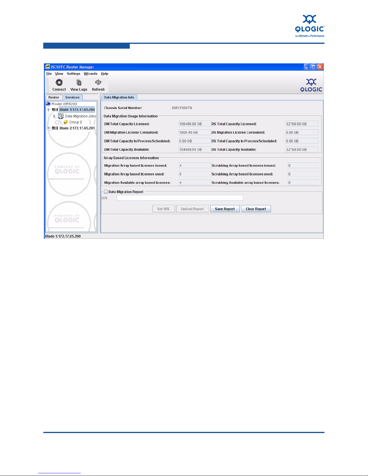
4–Data Migration Licenses
Viewing Data Migration and Scrubbing License Usage
Figure 4-7. Data Migration Info for a Blade
4-8 ISR654608-00 C
Page 63

5 Performing Data Migration
This chapter provides the following procedures for configuring and managing data
migration using DMS:
“Typical Data Migration Process” on page 5-2
“Configuring the Fabric” on page 5-3
“Presenting LUNs to the iSR6200” on page 5-4
“Presenting LUNs to the Server for Online Data Migration” on page 5-7
“Mapping Initiators to LUNs” on page 5-11
“Setting Array Properties” on page 5-12
“Creating a Data Migration Job Group” on page 5-14
“Using the Data Migration Wizard” on page 5-15
“Starting Serial Scheduled Jobs” on page 5-21
“Viewing the Status of Data Migration Jobs” on page 5-22
“Viewing Job Details and Controlling Job Actions” on page 5-22
“Viewing System and Data Migration Job Logs” on page 5-25
“Using the Verify Migration Job Wizard” on page 5-28
“Acknowledging a Data Migration Job” on page 5-30
“Removing an Offline Array” on page 5-33
“Creating and Removing a Data Management LUN” on page 5-33
“Using the Scrubbing LUN Wizard” on page 5-36
“Generating a Data Migration Report” on page 5-38
ISR654608-00 C 5-1
Page 64

5–Performing Data Migration
Typical Data Migration Process
Typical Data Migration Process
Table 5-1 shows the iSR6200 data migration process flow by category and
activity, and references the appropriate section for each.
Table 5-1. Data Migration Process Flow
Category Activity For Details, See…
1. Plan for data migration. Data Migration Service for iSR6200
Planning Guide
Pre-Migration
2. At the start of the project, clear the
migration logs.
3. Install license keys. “Installing a Data Migration License Key”
4. Configure the Fibre Channel fabric. “Configuring the Fabric” on page 5-3
5. Provide the iSR6200 access to LUNs
from source and destination arrays.
6. Discover arrays and set array properties.
7. Apply the array-based license key, if
an array-based migration license will
be consumed for this project. Otherwise per-TB license is used automatically.
8. For online data migration, present
source LUNs from the router to the
server and zone out direct paths from
the server to the source array. For
remote migration, also create a data
management LUN.
“Viewing System and Data Migration Job
Logs” on page 5-25
on page 4-2
“Presenting LUNs to the iSR6200” on
page 5-4
“Setting Array Properties” on page 5-12
“Applying an Array-based License to a
Specific Array” on page 4-4
“Presenting LUNs to the Server for
Online Data Migration” on page 5-7
9. Define user groups. “Creating a Data Migration Job Group”
Configure
Migration Jobs
5-2 ISR654608-00 C
10. Configure and validate data migration jobs.
on page 5-14
“Using the Data Migration Wizard” on
page 5-15
Page 65

5–Performing Data Migration
Configuring the Fabric
Table 5-1. Data Migration Process Flow (Continued)
Category Activity For Details, See…
Migrate and
Monitor
Post-Migration
11. For offline data migration, ensure that
server has no longer access to
source LUNs.
12. For online data migration, ensure that
Pre-Migration step 7 in this table is
completed.
13. For data migration jobs that are
scheduled for a delayed start, specify
the start time for the job.
14. Monitor data migration jobs. “Viewing Job Details and Controlling Job
15. Acknowledge the data migration
jobs.
16. Export data migration logs. “Viewing System and Data Migration Job
17. Remove arrays from persistence. “Removing an Offline Array” on
18. Check license usage. “Viewing Data Migration and Scrubbing
Deactivate zones 1 and 2 as described
in “Data Migration Configuration” on
page 2-3.
“Presenting LUNs to the Server for
Online Data Migration” on page 5-7
“Starting Serial Scheduled Jobs” on
page 5-21
Actions” on page 5-22
“Acknowledging a Data Migration Job”
on page 5-30
Logs” on page 5-25
page 5-33
License Usage” on page 4-6
Configuring the Fabric
Because iSR6200 online data migration presents multiple virtual Fibre Channel
ports to each physical Fibre Channel port, enable N_Port ID virtualization (NPIV)
support on the Fibre Channel switches. If the Fibre Channel switches (older 2Gb
Fibre Channel switches) do not support NPIV, or if you do allow the switch to be
configured with NPIV support, enable loop mode support on a Fibre Channel
switch port, and then configure the iSR6200 Fibre Channel ports in loop-preferred
or loop only mode; the default is loop-preferred. In the event that NPIV is not
supported or not enabled, and if the Fibre Channel switch port cannot be
configured to support loop mode, configure iSR6200 ports in point-to-point only
mode. In point-to-point only configuration of iSR6200 Fibre Channel ports, you
can perform only offline migration. NPIV and enabling NPIV support is not an
option.
ISR654608-00 C 5-3
Page 66

5–Performing Data Migration
Presenting LUNs to the iSR6200
Table 5-2 shows the behavior of iSR6200 Fibre Channel ports as determined by
the configuration of various Fibre Channel switch ports, where:
The Connect and Connect (loop mode) settings are appropriate for online
data migration.
The Connect (offline migration only) setting is appropriate for offline data
migration.
The No connect setting indicates that the link does not come up unless you
change the iSR6200 Fibre Channel port or switch port setting.
Table 5-2. iSR6200 Fibre Channel Port Settings
Fibre Channel Switch Port Setting
iSR6200
NPIV Supported and NPIV Enabled NPIV Not Supported or NPIV
Fibre
Channel
Port
Setting
Auto
(default)
Loop only Connect
P2P only Connect Connect No connect Connect
Table Notes:
1
Fabric port
2
Fabric loop port
3
Point-to-point
F_Port 1
and
3
or
2
F_Port
(P2P Only
No connect Connect
FL_Port
(Loop
Only)
(loop mode)
(loop mode)
FL_Port
(P2P
Loop)
Connect Connect Connect
(loop mode)
F_Port and
FL_Port
(P2Por
Loop)
Connect
(loop mode)
Connect
(loop mode)
(offline
migration
only)
Disabled
FL_Port
F_Port
(P2P Only)
No connect Connect
No connect Connect
Connect
(offline
migration
only)
(Loop
Only)
(loop mode)
(loop mode)
No connect
Presenting LUNs to the iSR6200
Data migration requires that LUNs from both the source and destination storage
arrays are presented to the iSR6200 as shown in the following sections:
“LUN Presentation from Fibre Channel Arrays” on page 5-5
“LUN Presentation from iSCSI Arrays” on page 5-6
5-4 ISR654608-00 C
Page 67

Presenting LUNs to the iSR6200
LUN Presentation from Fibre Channel Arrays
This section provides the procedures for presenting LUNs and discovering Fibre
Channel storage arrays for data migration.
To present source and destination LUNs from Fibre Channel arrays:
1. Zone in source array controller ports with appropriate iSR6200 VPGs (for
more information, see “Virtual Port Groups (VPGs)” on page 3-7). Create
and activate Zone 3 and Zone 4 as shown in Figure 2-5 on page 2-5 such
that each router blade can access all ports on source array controllers A and
B.
2. Zone in destination array controller ports with iSR6200 Fibre Channel ports.
Create and activate Zone 5 and Zone 6 as shown in Figure 2-8 on page 2-8
such that each router blade can access all ports on destination array
controllers A and B.
3. Present LUNs from both the source and destination array to the iSR6200 as
follows:
5–Performing Data Migration
a. Register the following router Fibre Channel WWPNs from the same
virtual port group (VPG) as a single “host entry” in the storage array:
BL1–FC1–VPG1
BL1–FC2–VPG1
BL2–FC1–VPG1
BL2–FC2–VPG1
For details on configuring VPGs on a Fibre Channel array, see the
iSR6200 Intelligent Storage Router Installation Guide, “Configuration”
chapter.
b. In the array management utility, set the VPG host type to Windows.
c. Present the LUNs (associated with the server) to the router as the
same LUN ID (if possible) as presented to the server. If multiple
servers are being migrated at the same time using the same iSR6200,
and different LUNs are presented from the storage array using the
same LUN IDs to different servers, you must present LUNs for different
servers to different VPGs of iSR6200. For details, see “Virtual Port
Groups (VPGs)” on page 3-7.
d. to the different server as the same LUN ID, you must use a different
host entry using a VPG for LUNs that belong to different servers. (For
details, refer to the Data Migration Service for iSR6200 Planning
Guide.)
ISR654608-00 C 5-5
Page 68

5–Performing Data Migration
Presenting LUNs to the iSR6200
4. (Optional) To discover the newly-presented LUNs and form the new arrays,
if required, follow these steps:
a. In the left pane of SANsurfer iSCSI/FC Router Manager, click the
Router tab.
b. Right-click the appropriate blade.
c. On the shortcut menu, click Rescan.
NOTE:
The iSR6200 supports a maximum of four VPGs. To expose more than 255
LUNs from any Fibre Channel storage array, you may enable additional
VPGs in the iSR6200 blades. To present up to 1,024 LUNs (4×256) from the
same array to the iSR6200, repeat the preceding steps for each VPG.
For details on LUN presentation to the iSR6200 through different vendor arrays,
refer to the Data Migration Service for iSR6200 Planning Guide.
LUN Presentation from iSCSI Arrays
This section provides the procedures for presenting LUNs and discovering iSCSI
storage arrays for offline data migration.
To present source and destination LUNs from iSCSI arrays:
1. Determine the iSCSI initiator name of each blade by issuing the show
iscsi command; see page 6-78.
2. Using an array management utility, register the router as a host using the
iSCSI qualified name (IQN) of the iSCSI port, and then assign LUNs to this
host.
NOTE:
Some iSCSI arrays require pre-registered hosts for the iscsi
discover command to succeed. For these arrays, manually create a
host with the IQN of the router iSCSI port before you issue the
command.
3. Using the CLI, discover iSCSI storage arrays by issuing the iscsi
discover command (see page 6-22).
4. List the discovered iSCSI targets, as well any Fibre Channel targets (if
present), by issuing the show targets command (see page 6-107).
5. Log into the iSCSI target by issuing the iscsi login command (see
page 6-23).
5-6 ISR654608-00 C
Page 69

5–Performing Data Migration
Presenting LUNs to the Server for Online Data Migration
After successful iSCSI login, the iSCSI target comes online.
NOTE:
If the iSCSI storage array supports it, you can establish multiple
connections per session using multiple GbE ports on the same router
blade and storage array.
6. (Optional) To discover the newly-presented LUNs and form the new arrays,
if required, follow these steps:
a. In the left pane of SANsurfer iSCSI/FC Router Manager, click the
Router tab.
b. Right-click the appropriate blade.
c. On the shortcut menu, click Rescan.
Presenting LUNs to the Server for Online Data
Migration
For online data migration, you need to create access to all LUNs associated with
the server or servers through the router, and you must eliminate direct access
from the server to the storage array.
Follow these basic steps to present the LUNs from the iSR6200 to the server:
Step 1: Present Source LUNs to the Initiator
Step 2: Create Presented Targets
Step 3: Zone in Presented Targets with Initiator Ports
Step 1: Present Source LUNs to the Initiator
Map the initiators to the LUN and create presented targets (virtual ports)
associated with the source array target ports and the VPG. (For more information,
see “Presented Targets” on page 3-9”.
QLogic recommends that you create the presented target on the same Fibre
Channel port of the iSR6200 on which the source array port is discovered.
Typically, Fibre Channel zoning is set up such that one source array port is
discovered through one Fibre Channel port (one or more VPGs) of the iSR6200. If
the same source array target port is discovered through multiple Fibre Channel
ports (on the same VPG) of the iSR6200, create only one presented target port
across both blades of the iSR6200.
ISR654608-00 C 5-7
Page 70

5–Performing Data Migration
Presenting LUNs to the Server for Online Data Migration
To present source array LUNs to the initiator for online data migration:
1. Use either the SANsurfer iSCSI/FC Router Manager or the CLI to create a
presented target:
In SANsurfer iSCSI/FC Router Manager, use the Target
Presentation/LUN Mapping Wizard to automatically detect the portal
on which the target is discovered and to create a presented target on
these portals. (See “Mapping Initiators to LUNs” on page 5-11).
Because SANsurfer Router Manager performs an array-based LUN
presentation, the LUN is presented to an initiator through all of the
discovered target ports. The visibility of a LUN through a target on the
initiator depends on your zoning configuration.
In the CLI, issue the lunmask add command (see “lunmask” on
page 6-24) and select the appropriate target and portal. For example:
HBA1 > SA1 > LUN1 > BL1 FC1 VPG1 creates presented
target PT1 (SA1 + VPG1)
HBA2 > SB2 > LUN1 > BL1 FC2 VPG1 creates presented
target PT4 (SB2 + VPG1)
2. (Optional) To discover the newly-presented LUNs and form the new arrays,
if required, follow these steps:
a. In the left pane of SANsurfer iSCSI/FC Router Manager, click the
Router tab.
b. Right-click the appropriate blade.
c. On the shortcut menu, click Rescan.
3. Repeat the preceding steps for the second blade so that the LUN is
accessible to the server through both blades.
Step 2: Create Presented Targets
If the presented target associated with the source array target port and the VPG
does not exist, you must create one. Use the Target Map Wizard to add a
presented target for each source array target port for the VPG from which LUNs
are being mapped to the host. Ensure that you create only one presented target
(associated with source array target port and the VPG) across both blades.
The following procedure shows an example configuration.
5-8 ISR654608-00 C
Page 71

Presenting LUNs to the Server for Online Data Migration
To create presented targets:
1. Configure the hosts as follows:
Host 1:
a. Present LUNs A, B, and C to the host as LUN ID 1, 2, and 3.
b. Present LUNs A, B, and C to iSR6200 VPG1 as LUNs 1, 2, and
3.
Host 2:
a. Present LUNs D, E, and F to the host as LUN ID 5, 6, and 7.
b. Present LUNs D, E, and F to iSR6200 VPG1 as LUN 5, 6, and 7.
Host 3:
a. Present LUNs G, H, and I to the host as LUN ID 1, 2, and 3.
b. Present LUNs G, H, and I to iSR6200 VPG2 as LUN ID 1, 2, and
3.
5–Performing Data Migration
This enables iSR6200 VPG1 and VPG2 to see all four source array target
ports through both blades.
2. Create the following presented targets when presenting the LUNs to Host 1
or Host 2:
PT1 is SA1+VPG1
PT2 is SA2+VPG1
PT3 is SB1+VPG1
PT4 is SB1+VPG1
3. Create the following additional presented targets when presenting LUNs to
Host 3:
PT4 is SA1+VPG2
PT5 is SA2+VPG2
PT6 is SB1+VPG2
PT7 is SB1+VPG2
Step 3: Zone in Presented Targets with Initiator Ports
Zone in appropriate presented targets with initiator ports on the server. After
completing LUN and target presentation from the iSR6200 to the server, follow
these recommended steps to insert the iSR6200 in the data path and remove
direct access between the host and storage array. Depending on the source array
type (active-active or active-passive) and configuration (cluster or non-cluster),
these steps may vary.
ISR654608-00 C 5-9
Page 72

5–Performing Data Migration
Presenting LUNs to the Server for Online Data Migration
NOTE:
For information about online insertion of the iSR6200 in the data path in a
cluster configuration, see the QLogic applications note, iSR6200 Data
Migration for Cluster Configurations.
You can use either one of the methods in this section for single server
configuration. In addition, refer to the following:
For a description of Fibre Channel zones, see Figure 2-5 on page 2-5.
For operating system specific details, refer to Appendix A Configuring the
Data Path Through iSR6200 for Online Data Migration.
Zoning in Presented Targets: Method 1
Source array: active-passive or active-active
Single server configuration: non-cluster
This method represents a conservative approach. In this method, you remove one
direct path from the source array, and then enable an equivalent path from the
iSR6200. This method requires multiple zoning steps.
1. Remove SA1 from Zone1, and then validate the I/O failover to another path.
2. Activate Zone9, and then validate the new path.
3. Remove SB1 from Zone1, and then validate I/O failover to another path.
4. Activate Zone11, and then validate the new path.
5. Remove SA2 from Zone2, and then validate I/O failover to another path.
6. Activate Zone10, and then validate the new path.
7. Remove SB2 from Zone2, and then validate I/O failover to another path.
8. Activate Zone12, and then validate the new path.
Zoning in Presented Targets: Method 2
Source array: active-active
Single server configuration: non-cluster
Use this method when dealing with arrays that support active-active configuration,
where LUNs are accessible simultaneously through both controllers. Such LUNs
have paths that are either active-optimized or active-unoptimized. Most 4Gb Fibre
Channel arrays support such configurations, as do 2Gb Fibre Channel arrays from
the EMC Symmetrix
9900 families.
®
family, HP XP family, and Hitachi Data Systems USP and
5-10 ISR654608-00 C
Page 73

1. Activate Zone9, Zone10, Zone11, and Zone12.
2. Validate the new paths. The paths through iSR6200 are enabled.
3. Remove Zone1 and Zone2. Direct paths are removed.
Mapping Initiators to LUNs
SANsurfer iSCSI/FC Router Manager provides the Target Presentation/LUN
Mapping Wizard to map Fibre Channel initiators to LUNs for online data migration.
This mapping provides the access for the LUN to the host from the router through
a presented virtual target. Mapping is required as a part of the process of inserting
the router in the host I/O path. You must ensure that the entire host I/O is routed
by the router, and that there is no direct access to any source controller ports from
the host during migration.
NOTE:
LUN mapping is required only for online data migration for Fibre Channel
initiators (iSCSI initiators are not supported). LUN mapping is not
required for offline data migration.
For HP-UX initiators, set the host type to HP-UX in the iSR6200. For all
other initiators, leave the host type set to Windows, the default.
For arrays that have a dedicated controller LUN (for example, LUN-0 on
HP EVA arrays), ensure that LUN-0 is also presented to the Fibre
Channel initiators hosts with the actual data LUNs.
5–Performing Data Migration
Mapping Initiators to LUNs
To map a Fibre Channel initiator to a LUN:
1. On the Wizards menu, click Presentation Wizard to open the Target
Presentation/LUN Mapping Wizard.
2. On the Select the Initiators for the LUN Presentation window, select a Fibre
Channel initiator, and then click Next.
3. On the LUN Selection window, select one or more LUNs for the selected
virtual port group node, and then click Next.
On the Portal Selection window, the router automatically detect the portals
through which the array target ports are accessible. QLogic recommends
that you present a single source, array target port and VPG only once
across both blades. Figure 2-8 on page 2-8 shows that when source arrays
ports SA1, SA2, SA3, and SA4 are discovered on VPG1, only one
corresponding presented target is created on PT-SA1, PT-SA2, PTSA3, and
PT-SA4.
4. Select a portal to use for target mapping (or None), and the click Next.
ISR654608-00 C 5-11
Page 74

5–Performing Data Migration
Setting Array Properties
NOTE:
The Portal Selection window appears only when there is no existing
mapping. This window does not appear if the target map is created
separately using the Target Map Wizard, or if it exists as part of a
previous LUN presentation through this array.
The LUN Masking Configuration Status opens, and the Security Check
dialog box prompts you to enter the admin password.
5. Type the admin password, and then click Next.
6. On the LUN Masking Configuration Status window, review the results of the
target ports presented for the selected initiators, and then click Finish.
Setting Array Properties
SANsurfer iSCSI/FC Router Manager enables you to configure the target type and
bandwidth, and to enable load balancing, for each storage array used in data
migration.
To set array properties:
1. In the left pane, click Arrays to view all the Fibre Channel storage arrays
detected by the iSR6200.
2. Click the storage array you want to use as the source array.
The Information page in the right pane displays all the properties currently
set for the selected array. Figure 5-1 shows an example.
5-12 ISR654608-00 C
Page 75
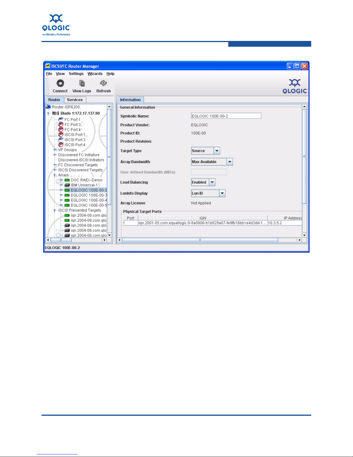
5–Performing Data Migration
Setting Array Properties
Figure 5-1. Information Page: Setting Array Properties
3. (Optional) In the Symbolic Name box, type a user-friendly array name.
4. From the Target Typ e list, select Source.
NOTE:
Array bandwidth is only displayed and editable if the array target type
is Source.
5. From the Array Bandwidth list, click one of the following values:
Slow (50MB/s)
Medium (200MB/s)
Fast (1600MB/s)
User Defined
Max Available
ISR654608-00 C 5-13
Page 76

5–Performing Data Migration
Creating a Data Migration Job Group
6. If you select User Defined, type a value between 50 and 1600 in the User
Defined Bandwidth (MB/s) box. By default, the iSR6200.uses all available
bandwidth; the minimum bandwidth required for data migration is 50Mbps.
7. For Load Balancing, click either Enabled or Disabled. By default, load
balancing is enabled.
8. For LUN Info Display, specify whether the array’s LUNs are identified by
LUN ID, WWULN, or Serial Number.
9. To save your changes, click Save.
10. If the Data Migration Security Check dialog box opens, enter the
administrative password. (The default password is migration.)
SANsurfer iSCSI/FC Router Manager displays an informative message
indicating that the array properties have changed.
11. Click OK to close the message box.
12. To apply the changes and update the window before changing other array
properties, click Refresh.
Creating a Data Migration Job Group
Follow these steps to create a data migration job group in SANsurfer iSCSI/FC
Router Manager.
To create a data migration job group:
1. In the left pane, click the Services tab to open the Services page.
By default, the iSR6200 shows Group 0 created under the Data Migration
Jobs item in the left pane.
2. In the left pane, right-click Data Migration Jobs, and then on the shortcut
menu, click Add Group. (Or on the Wizards menu, click Add Group.)
3. In the Create New Group dialog box, type a group name that you want to
assign to administer a set of data migration jobs, and then click OK.
4. In the Data Migration Security Check dialog box, type the data migration
user password (default is migration), and then click OK.
5-14 ISR654608-00 C
Page 77

Using the Data Migration Wizard
The Data Migration wizard helps simplify the configuration and scheduling of both
individual and batches of data migration jobs. The following sections provide
wizard details:
“Starting the Data Migration Wizard” on page 5-15
“Scheduling an Individual Data Migration Job” on page 5-15
“Scheduling Data Migration Jobs in Batch Mode” on page 5-19
Starting the Data Migration Wizard
Follow these steps to start the data migration wizard, and then proceed with
scheduling either an individual or batch data migration job.
To start the data migration wizard:
1. Start SANsurfer iSCSI/FC Router Manager and connect to the iSR6200 by
providing the IP address of the iSR6200.
2. Start the data migration wizard using one of these methods:
5–Performing Data Migration
Using the Data Migration Wizard
On the Wizards menu, click Configure Migration Jobs.
In the left pane, open the Services page, right-click the Data Migration
Jobs node, and then click Configure Migration Jobs.
3. If the Data Migration Security Check dialog box appears, type the data
migration user password (default is migration), and then click OK.
4. In the Create Data Migration Job dialog box, click Options.
5. In the Migration Schedule Options dialog box, select either Schedule in
batch mode or Schedule individual job.
6. Click OK.
7. Depending on your selection in the preceding step, continue with either
“Scheduling an Individual Data Migration Job” on page 5-15 or “Scheduling
Data Migration Jobs in Batch Mode” on page 5-19.
Scheduling an Individual Data Migration Job
Follow these steps to schedule an individual data migration job in SANsurfer
iSCSI/FC Router Manager.
To schedule an individual data migration job:
1. Start the data migration wizard by following the steps specified in “Starting
the Data Migration Wizard” on page 5-15.
2. In the Migration Schedule Options dialog box, click Schedule individual
job, and then click OK.
ISR654608-00 C 5-15
Page 78

5–Performing Data Migration
Using the Data Migration Wizard
3. Expand the nodes in the right pane of the Create Data Migration Job dialog
box to see the type of array (Source, Destination, or Src+Dest) for each of
the arrays available for configuring the data migration job. Figure 5-2 shows
an example.
Figure 5-2. Create Data Migration Job Dialog Box
4. Choose the appropriate source and destination LUN for the data migration
job by dragging and dropping the LUNs from the right pane onto the Source
LUN or Destination LUN for the data migration job in the left pane.
NOTE:
SANsurfer iSCSI/FC Router Manager does not allow you to drag a
LUN from an array of Source type in the right pane and drop it onto the
Destination LUN in the left pane. However, if the array type is
Src+Dest, you can drop the LUN from that array onto either a Source
LUN or Destination LUN in the left pane.
If you attempt to drop a Source LUN from the right pane onto a
Destination LUN of a smaller size in the left pane, an error message
notifies you of the size discrepancy.
5-16 ISR654608-00 C
Page 79

5–Performing Data Migration
Using the Data Migration Wizard
The Data Migration Jobs Options dialog box opens. Figure 5-3 shows an
example.
Figure 5-3. Data Migration Jobs Options Dialog Box
5. In the Data Migration Jobs Options dialog box, specify the job attributes as
follows:
a. Under Migration Type, select one of the following:
Click Offline (Local/Remote) to schedule a data migration job in
which the servers affected by the migration job are down.
Click Online (Local) to schedule a data migration job in which
disconnecting server access to the LUN is not required. You
must, however, ensure that the router is inserted correctly in the
host I/O path and that no other paths from the server have
access to the source LUN.
Click Online (Remote) to schedule a data migration job for which
a data management LUN (DML) exists. If a DML has not been
previously configured, the online remote migration job
configuration fails.
NOTE:
If the source LUN is mapped to an initiator, Online (Local) data
migration is selected by default. Otherwise, the migration type
defaults to Offline (Local/Remote).
ISR654608-00 C 5-17
Page 80

5–Performing Data Migration
Using the Data Migration Wizard
b. Under Scheduling Type, select one of the following:
Click Start Now to start the job immediately.
Click Schedule for Later, and then enter a Start Time and Start
Click Serial Schedule Jobs, and then assign a priority (1–256)
Click Configure Only to configure the migration job without any
You may start this job at a later time. (To start the job, select it, and
then click Start. Or, from the active job pane, right-click the job, and
then click Start.)
c. In the Job Description box, type a user-defined name to describe this
data migration job.
Date.
in the Job Priority box, where a lower value indicates that the
job is scheduled earlier than jobs configured with higher values.
For details on Serial Schedule Jobs, see “Starting Serial
Scheduled Jobs” on page 5-21.
start time or priority.
d. In the Group Name box, select a job group name from the list. The
group name makes it easier to view the job status on a group basis.
e. In the TP Settings box, select one of the following options for a
thin-provisioned LUN:
No TP: The destination LUN is not thin-provisioned; the option is
disabled.
Yes, and No Validation: Select this option when the destination
LUN is known to be a thin-provisioned storage and is newly
created.
Yes and TP Validation: Select this option if you are uncertain
about the data on the destination LUN, or if the destination LUN
was used earlier for storing any other data. Enabling validation
ensures that no corruptions exist because of stale data on the
destination LUN. Enabling validation provides additional
processing overhead. Typically, validation is not required for a
LUN newly created for data migration.
f. In the IO Size box, select one of the default I/O sizes.
5-18 ISR654608-00 C
Page 81

5–Performing Data Migration
Using the Data Migration Wizard
g. For offline migration jobs only, select the Verify Data After Migration
Finished check box to validate migrated data by reading it from the
source LUN and comparing it to the destination LUN. (This option is
not available for online migration jobs.)
6. To save the data migration job options, click Apply. Or to abandon changes
to this data migration job, click Cancel.
Scheduling Data Migration Jobs in Batch Mode
Batch mode for data migration jobs is a feature inSANsurfer iSCSI/FC Router
Manager used to schedule multiple jobs having the same priority, I/O size, and
group options.
This option is particularly useful for migration jobs specified as Schedule for later
and Serial Schedule Jobs on the Data Migration Jobs Options dialog box (see
Figure 5-3 on page 5-17), where the jobs need to be classified under a specific
group for better management.
DMS allows a maximum of eight jobs to run simultaneously at any specific time
per source array. To optimize iSR6200 performance, QLogic recommends that
you run simultaneously no more than four jobs on any specified source or
destination array.
Consider a data center having multiple applications running on multiple storage
arrays that need to be consolidated, and data migration needs to be done on
associated LUNs. The data migration administrator must plan the data migration
operation to minimize the application downtime. In order to achieve this,
SANsurfer iSCSI/FC Router Manager provides an option to create data migration
job groups, as described in “Creating a Data Migration Job Group” on page 5-14.
You can combine all the source LUNs associated with a specific application into a
single job group and schedule it for migration using the Schedule in batch mode
option. That way all the jobs can start at a predefined time, which can be off-peak
hours when the administrator can afford a small application downtime.
To schedule data migration jobs in batch mode:
1. Start the data migration wizard by following the steps specified in “Starting
the Data Migration Wizard” on page 5-15.
2. In the Migration Schedule Options dialog box, click Schedule in batch
mode, and then click OK.
Expand the nodes in the right pane of the Create Data Migration Job dialog
box to see the type of array (Source, Destination, or Src+Dest) for each of
the arrays available for configuring the data migration job. Figure 5-2 on
page 5-16 shows an example.
ISR654608-00 C 5-19
Page 82

5–Performing Data Migration
Using the Data Migration Wizard
3. Choose the appropriate source and destination LUN for the migration job by
dragging and dropping the LUNs from the right pane onto the Source LUN
or Destination LUN under Data Migration Job (New) in the left pane.
SANsurfer iSCSI/FC Router Manager populates the Source LUN and
Destination LUN attributes and creates a new Data Migration Job (New)
object below the first one. The default job name is created by using the
source and destination array names.
4. Repeat the preceding steps to create migration jobs for all source LUNs to
be migrated in a batch.
5. To save your migration job and assign job attributes, click Schedule. Or, to
abandon your changes, click Close.
6. In the Data Migration Jobs Options dialog box (see Figure 5-3 on page
5-17), specify the job attributes as follows:
a. Under Scheduling Type, select one of the following:
Click Start Now to start the job immediately.
Click Schedule for Later, and then enter a Start Time and Start
Date.
Click Serial Schedule Jobs, and then assign a priority (1–256)
in the Job Priority box, where a lower value indicates that the
job is scheduled earlier than jobs configured with higher values.
For details on Serial Schedule Jobs, see “Starting Serial
Scheduled Jobs” on page 5-21.
Click Configure Only to configure the migration job without any
start time or priority.
You may start a configure-only job at a later time. (To start the
job, select it, and then click Start. Or, from the active job pane,
right-click the job, and then click Start.)
b. In the Job Description box, type a user-defined name to describe this
data migration job.
c. In the Group Name box, select a job group name from the list. The
group name makes it easier to view the job status on a group basis.
d. In the IO Size box, select one of the default I/O sizes.
e. Under Migration Type, select one of the following:
Click Online to schedule a data migration job in which
disconnecting server access to the LUN is not required, or a
remote online job. You must, however, ensure that the router is
inserted correctly in the host I/O path and that no other paths
from the server have access to the source LUN.
5-20 ISR654608-00 C
Page 83

Click Offline to schedule a data migration job in which the
servers affected by the migration job are down.
7. To save the data migration job options, click Apply. Or to abandon changes
to this data migration job, click Cancel.
Starting Serial Scheduled Jobs
If the individual or batch data migration job you created was configured as a
Serial Schedule Jobs scheduling type on the Data Migration Jobs Options dialog
box, the job is listed on the Active Data Migration Jobs page. The Status column
shows the job as Serial Scheduled.
To start a serial scheduled job:
1. Open the Serial Data Migration Jobs Options dialog box (see Figure 5-4)
using one of these options:
On the Wizards menu, click Start Serial Schedule Job(s).
Right-click a serial scheduled job, and then click Start Serial
Scheduled Jobs. This option immediately starts the selected job,
unless there are other jobs configured with a lower priority that must
complete migration first.
5–Performing Data Migration
Starting Serial Scheduled Jobs
Figure 5-4. Serial Data Migration Jobs Options
2. Under Scheduling Type, click either Start Now or Schedule for later.
3. If you choose Schedule for later, enter the Start Time and Start Date.
4. To save your settings, click Apply.
5. On the Data Migration Security Check dialog box, type your security
password (the default is migration), and then click OK.
The serial scheduled jobs starts when you have scheduled.
ISR654608-00 C 5-21
Page 84

5–Performing Data Migration
Viewing the Status of Data Migration Jobs
Viewing the Status of Data Migration Jobs
The right pane of the SANsurfer iSCSI/FC Router Manager displays the job status
for all active and completed data migration jobs that you have configured.
To view the status of data migration jobs:
1. In the left pane, click the Services tab.
2. In the left pane, expand a blade node, and then click the Data Migration
Jobs node.
3. In the right pane, click the Active Data Migration Jobs tab.
The Active Data Migration Jobs page in the right pane shows a summarized
view of all active jobs, including the following columns of information:
Group Name % Completed
Job ID Start Time
Job Name End Time
Typ e Source Array–LUN
Status Dest Array–LUN
NOTE:
You can also pause, resume, stop, start, and remove active data
migration jobs using the shortcut menu on the Active Data Migration
Jobs page. For more information on job actions, see “Viewing Job
Details and Controlling Job Actions” on page 5-22.
4. To see a summarized view of all completed jobs, click the Completed Data
Migration Jobs tab in the right pane.
5. To view a list of all jobs, click Data Migration Jobs in the left pane.
6. To view a list of all jobs belonging to a specific migration group, click the
migration group name in the left pane.
Viewing Job Details and Controlling Job Actions
SANsurfer iSCSI/FC Router Manager provides a view of the details of data
migration jobs. From the detailed view, you can also control job actions, including
pausing, stopping, deleting, resuming, and restarting the job.
5-22 ISR654608-00 C
Page 85

5–Performing Data Migration
Viewing Job Details and Controlling Job Actions
To view data migration job details:
1. In the left pane, click the Services tab.
2. In the left pane, expand a blade node, and then click the Data Migration
Jobs node.
3. In the left pane, under the Data Migration Jobs node, expand a Group x
node, and then select a migration job by clicking the appropriate JobID.
Details for the specified job are listed in the Data Migration Job page in the
right pane. Figure 5-5 shows an example.
ISR654608-00 C 5-23
Page 86

5–Performing Data Migration
Viewing Job Details and Controlling Job Actions
Figure 5-5. Data Migration Job Page: Job In Progress
5-24 ISR654608-00 C
Page 87

5–Performing Data Migration
Viewing System and Data Migration Job Logs
NOTE:
For online data migration jobs, log details include the Number of DRL
(Dirty Region Log) Blocks; for offline data migration, DRL count is not
applicable.
4. (Optional) On the Data Migration Job page, perform any of the following job
control actions as needed:
Click Pause to interrupt a running migration job.
Click Stop to halt a running migration job.
Click Remove to delete a migration job.
Click Resume to continue a previously paused migration job.
Click Start to restart a previously stopped migration job.
NOTE:
The action buttons that are shown are specific to the selected
migration job. For example, the Pause and Stop buttons are only
shown for a job that is currently running, the Resume button is only
shown for a job that is currently paused or stopped, and the Start
button is only shown for a job that is currently not running.
For completed data migration jobs, this page includes an
Acknowledge button instead of the Start and Remove buttons. See
“Acknowledging a Data Migration Job” on page 5-30 for more
information.
You can also perform the preceding job control actions on the Active Data
Migration Jobs page (shown when you click a group under the Data Migration
Jobs node in the left pane). To do so, right-click a specific job, and then click the
appropriate action on the shortcut menu.
Viewing System and Data Migration Job Logs
SANsurfer iSCSI/FC Router Manager provides two types of logs: system and data
migration job. This section describes how to open and view each log type.
System Log
To view the system log:
1. On the SANsurfer iSCSI/FC Router Manager main window, click the View
Logs button.
2. In the Log Type dialog box, click System Logs.
ISR654608-00 C 5-25
Page 88

5–Performing Data Migration
Viewing System and Data Migration Job Logs
The Router Log (System Log) dialog box opens and lists the date and time,
application type, and description of each log entry. Informational entries are
shown with a white background, and error entries are shown with a red
background, as shown in Figure 5-6.
Figure 5-6. Router Log (System Log) Dialog Box
3. Use the buttons on the bottom of the Router Log (System Log) dialog box to
perform the following actions:
Click OK to close the log window after you have finished viewing it.
Click Clear to delete the contents of the log.
Click Export to download the logs in CSV file format that can be
viewed in any spreadsheet application, such as Microsoft Excel.
Click Print to send the contents of the log to a printer.
4. To view the time stamp and description for a single log entry, double-click
the entry to open it in the Log Details dialog box (see Figure 5-7). You can
scroll through the log entries in this dialog box by clicking the Next and
Previous buttons; to stop viewing log details, click Close.
5-26 ISR654608-00 C
Page 89

Figure 5-7. Log Details Dialog Box
Data Migration Job Log
The migration log lists the details of all started, stopped, paused, removed,
completed, failed, and acknowledged jobs. (Running jobs are not listed.)
To view the data migration job log:
1. On the SANsurfer iSCSI/FC Router Manager main window, click the View
Logs button.
5–Performing Data Migration
Viewing System and Data Migration Job Logs
2. In the Log Type dialog box, click Data Migration Logs.
The Router Log (Migration Log) dialog box opens and lists the following
columns of information, as shown in Figure 5-8:
SeqID is the sequential ID of log entries.
Time Stamp is the log entry time, based on router system time.
Group Name is the user-defined job group or Group 0.
Job Name is the user-defined name for the job.
Job ID is a numeric ID.
Job Type is the migration job type (COMPARE or MIGRATION).
Operation is the task or action (ADDED, STARTED, COMPLETED, or
ACK).
Source Array–LUN is the migration source LUN.
Source WWULN is the world wide unique LUN name for the source
array.
Dest Array–LUN is the migration destination LUN.
Dest WWULN is the world wide unique LUN name for the destination
array.
Migr Size is the size of the migration job (source LUN).
ISR654608-00 C 5-27
Page 90

5–Performing Data Migration
Using the Verify Migration Job Wizard
Figure 5-8. Router Log (Migration Log) Dialog Box
3. Use the buttons on the bottom of the Router Log (Migration Log) dialog box
to perform the following actions:
Click OK to close the log window after you have finished viewing it.
Click Clear to delete the contents of the log.
Click Export to download the logs in CSV file format that can be
viewed in any spreadsheet application, such as Microsoft Excel.
Using the Verify Migration Job Wizard
The configure verifying jobs wizard helps you configure verification jobs to
compare data residing on two LUNs. This ensures the data integrity of the
migration process by performing a bit-by-bit comparison of the data on the source
LUN with the corresponding data on the destination LUN. Job verification helps
ensure that the source data migrated successfully without any data loss or
corruption. You can configure a verification job on a pair of source and destination
LUNs only after the migration job configured on that pair has been completed and
acknowledged.
The configure verifying jobs wizard is generally the same as the data migration
wizard (see “Using the Data Migration Wizard” on page 5-15). All scheduling
options and job state changes (start, stop, pause, and so on) apply in the same
way to both verification and migration jobs.
5-28 ISR654608-00 C
Page 91

This section provides the following wizard details:
Starting the Verify Migration Job Wizard
Scheduling Verification of Job Options
Starting the Verify Migration Job Wizard
Follow these steps to start the configure verifying jobs wizard.
To start the configure verifying jobs wizard:
1. Start SANsurfer iSCSI/FC Router Manager and connect to the iSR6200.
2. Start the configure verifying jobs wizard using one of these methods:
On the Wizards menu, click Configure Verifying Jobs.
In the left pane, open the Services page, right-click on either the Blade
or Data Migration Jobs node, and from the shortcut menu, click
Configure Verifying Job.
3. In the Data Migration Security Check dialog box, enter your miguser
password (the default is migration), and then click OK.
5–Performing Data Migration
Using the Verify Migration Job Wizard
Scheduling Verification of Job Options
Follow these steps to schedule the verification of job options.
To schedule job option verification:
1. In the Verify Migration Job dialog box, click Options.
2. In the Verify Schedule Options dialog box, select the Scheduling Mode:
either batch mode or individual job, and then click OK.
3. Add the source and destination LUN. For details, see “Using the Data
Migration Wizard” on page 5-15.
4. Click Schedule.
The Verifying Jobs Options dialog box opens. Figure 5-9 shows an example.
ISR654608-00 C 5-29
Page 92
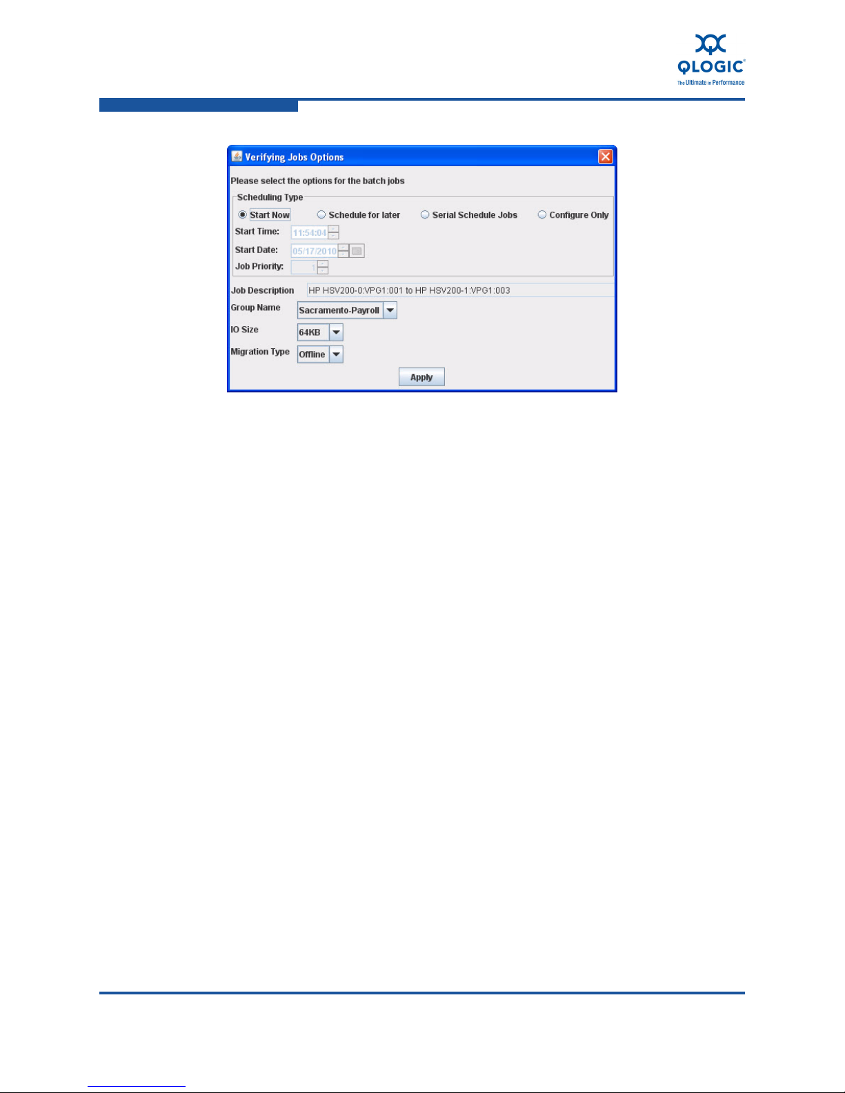
5–Performing Data Migration
Acknowledging a Data Migration Job
Figure 5-9. Verifying Jobs Options Dialog Box
5. The contents of the Verifying Jobs Options dialog box are identical to the
Data Migration Jobs Options dialog box. For an explanation of the selections
on this dialog box, see “Using the Data Migration Wizard” on page 5-15.
6. To save the verifying jobs options, click Apply. Or, to abandon changes to
this job verification, click Cancel.
Acknowledging a Data Migration Job
The last action to complete a migration requires acknowledging the job. When you
acknowledge a completed data migration job, SANsurfer iSCSI/FC Router
Manager does the following:
Provides final synchronization of data between the source and destination
LUN.
Creates a job report in the migration log and job report.
Removes the job from the system.
This section provides information on the following types of acknowledgments:
“Acknowledging Offline Migration Jobs” on page 5-31
“Acknowledging Online, Local Migration Jobs” on page 5-31
“Acknowledging Online, Remote Migration Jobs” on page 5-31
5-30 ISR654608-00 C
Page 93

Acknowledging a Data Migration Job
Acknowledging Offline Migration Jobs
When jobs are completed, SANsurfer iSCSI/FC Router Manager transitions offline
migration jobs, verify jobs, and data scrubbing jobs to the Completed Data
Migration Job page. For the router to release job resources, you must
acknowledge the job.
To acknowledge a completed offline data migration job:
1. In the left pane of SANsurfer iSCSI/FC Router Manager, click the Services
tab, and in the left pane under a blade node, click Data Migration Jobs.
2. In the right pane, click the Completed Data Migration Jobs tab to bring that
page to the front.
3. On the Completed Data Migration Jobs page, right-click a job that is
specified as 100% in the % Completed column.
4. On the shortcut menu, click Acknowledge Completed Data Migration.
Acknowledging Online, Local Migration Jobs
5–Performing Data Migration
When initial copy jobs for online, local migration are completed, SANsurfer
iSCSI/FC Router Manager transitions the migration jobs to the Completed Data
Migration Job page. Before you can acknowledge these jobs, you must bring
offline the server and application, and “unpresent” LUNs from the iSR6200 to the
server.
When you acknowledge an online, local data migration job, SANsurfer iSCSI/FC
Router Manager provides final synchronization of data between the source and
destination LUN. Because online migration jobs act like a synchronous mirror
operation, dirty regions are seldom left.
To acknowledge a completed online, local data migration job:
1. In the left pane of SANsurfer iSCSI/FC Router Manager, click the Services
tab, and in the left pane under a blade node, click Data Migration Jobs.
2. In the right pane, click the Completed Data Migration Jobs tab to bring that
page to the front.
3. On the Completed Data Migration Jobs page, right-click a job that is
specified as 100% in the % Completed column.
4. On the shortcut menu, click Acknowledge Completed Data Migration.
Acknowledging Online, Remote Migration Jobs
When initial copy jobs for online, remote migration are completed, SANsurfer
iSCSI/FC Router Manager transitions the migration jobs to the Synchronizing
Jobs Group page. Before you can acknowledge these jobs, you must bring offline
the server and application, and unpresent LUNs from the iSR6200 to the server.
ISR654608-00 C 5-31
Page 94

5–Performing Data Migration
Acknowledging a Data Migration Job
When you acknowledge an online, remote data migration job, SANsurfer
iSCSI/FC Router Manager provides final synchronization of data between the
source and destination LUN. Because offline migration jobs act like a
synchronous mirror operation, a large number of dirty regions (blocks) may
remain unsynchronized, depending on the change rate of the data. Before
planning server and application down time, it is essential that you monitor how
many dirty blocks are remaining. Depending on the number of dirty blocks and the
available WAN bandwidth, the time to complete final synchronization may vary.
Figure 5-10 shows the Synchronizing Jobs Group page.
Figure 5-10. Synchronizing Jobs Group Page
To acknowledge a completed online, remote data migration job:
1. In the left pane of SANsurfer iSCSI/FC Router Manager, click the Services
tab, and in the left pane under a blade node, click Data Migration Jobs.
2. In the right pane, click the Synchronizing Jobs Group tab to bring that
page to the front.
3. On the Synchronizing Jobs Group page, right-click a job that is specified as
in a Copy-Complete/Synchronizing state.
5-32 ISR654608-00 C
Page 95

4. On the shortcut menu, click Acknowledge Completed Data Migration.
The acknowledged, remote migration jobs enter the final synchronizing state
and are shown as Acknowledged / Synchronizing.
Removing an Offline Array
You should remove arrays used in data migration because they are kept in
persistent storage. If you used an array-based license for the data migration job
and you plan to use this array again for migration, you may keep the license when
removing the array.
The iSR6200 allows you to remove only offline arrays. To change the array state
to offline, move all array target ports to an offline state by removing target ports
from the router port zone.
To remove an offline array:
1. In the left pane of SANsurfer iSCSI/FC Router Manager, click the Router
tab.
5–Performing Data Migration
Removing an Offline Array
2. Under Arrays, right-click the name of the offline array you want to remove.
3. On the shortcut menu, click Remove Offline Array.
Creating and Removing a Data Management LUN
This section provides the steps to create a data management LUN (DML) and
remove a DML in SANsurfer iSCSI/FC Router Manager. For a description of the
data management LUN, see “Data Management LUN (DML)” on page 3-10.
To create a data management LUN in SANsurfer Router Manager:
1. Start the Create Data Management LUN Wizard using one of these
methods:
On the Wizards menu, click Create Data Management LUN, and then
in the Select Blade dialog box, choose Blade 1 or Blade 2.
In the system tree pane, right-click a blade, and then click Create Data
Management LUN to add a DML to the selected blade.
Right-click in the system tree pane, and then click Create Data
Management LUN to add a DML to the default blade, Blade 1.
2. Complete the Create Data Management LUN Wizard as follows:
a. Select a storage array for this DML.
b. Expand a VPGROUP_n node, and then select one or more LUNs by
selecting the check box to the left of each. Figure 5-11 shows an
example.
ISR654608-00 C 5-33
Page 96

5–Performing Data Migration
Creating and Removing a Data Management LUN
Figure 5-11. Create Date Management LUN Wizard
c. To save your changes and close the wizard, click OK.
The wizard verifies that all LUNs selected for the DML meet the following
criteria:
The LUN is not already used as a DML.
The LUN is not mapped to an initiator.
The LUN is not currently part of a migration, compare, or scrub job.
The LUN is greater than 50GB in size.
The LUN is online on one of the blades.
If the LUN does not meet all of the preceding criteria, the wizard rejects the
LUN and the DML creation operation fails with the appropriate error
message.
3. (Optional) To view the attributes of a DML, select a DML node under Data
Management LUNs in the SANsurfer Router Manager system view pane.
The Data Management LUN Info appears in the right pane; Figure 5-12
shows an example.
5-34 ISR654608-00 C
Page 97

5–Performing Data Migration
Creating and Removing a Data Management LUN
Figure 5-12. Viewing Data Management LUN Info
After using the DML for data migration, you should release (remove) it. You
cannot remove the “master” DML (the first DML created) until all other DMLs are
removed. That is, to remove all DMLs, you must remove the master DML last.
To remove a DML in SANsurfer iSCSI/FC Router Manager:
1. On the Wizards menu, click Remove Data Management LUN.
Or, in the system tree pane, right-click a blade, and then click Remove Data
Management LUN to remove a DML from the selected blade. Or, right-click
in the system tree pane, and then click Remove Management LUN to
remove a DML from the default blade, Blade 1.
2. Complete the Remove Data Management LUN Wizard as follows:
a. Select one or more DMLs by selecting the check box to the left of
each.
b. Click OK to save your changes and close the wizard.
ISR654608-00 C 5-35
Page 98

5–Performing Data Migration
Using the Scrubbing LUN Wizard
Using the Scrubbing LUN Wizard
The scrubbing LUN wizard helps you configure scrubbing jobs to wipe out data
residing on the LUN. This feature is primarily used to erase confidential
information on the LUN. Ensure that the information is no longer going to be used
by any application.
The scrubbing LUN wizard is generally the same as the data migration wizard
(see “Using the Data Migration Wizard” on page 5-15). However, you must select
only source LUNs on the Create LUN Scrubbing Job dialog box. Figure 5-13
shows an example.
Figure 5-13. Create LUN Scrubbing Job Dialog Box
As a security measure, SANsurfer Router Manager does not allow you to select
mapped LUNs or LUNs that are part of other jobs. In addition, destination arrays
are filtered out and do not appear in the right pane of the LUN selection window.
All scheduling options and job state changes (start, stop, pause, and so on) apply
in the same way to both scrubbing and migration jobs. For scrubbing jobs, you
can additional specify one of several scrubbing algorithms. The current firmware
release provides the following algorithms and passes:
5-36 ISR654608-00 C
Page 99

5–Performing Data Migration
Using the Scrubbing LUN Wizard
ZeroClean: Two passes
DOD_5220_22_M: Four passes
DOD_5220_22_M_E: Four passes
DOD_5220_22_M_ECE: Eight passes
Figure 5-14 shows an example of the scrubbing job options.
Figure 5-14. Scrubbing Job Options Dialog Box
To view the scrubbing job details, select the appropriate job in the appropriate
group, as shown in Figure 5-15.
ISR654608-00 C 5-37
Page 100

5–Performing Data Migration
Generating a Data Migration Report
Figure 5-15. Scrubbing Job Page
Generating a Data Migration Report
SANsurfer iSCSI/FC Router Manager provides reporting of data migration jobs
that have either been acknowledged or removed from the system. Each migration
job entry in the report lists the job details, including source and destination LUN
information. You can generate migration reports in three formats: TXT, JSON, and
XML. The TXT format is human readable; the JSON and XML formats are suitable
for automation by scripts developed to parse the reports and present the data on a
Web site or other external application.
5-38 ISR654608-00 C
 Loading...