


iSR6250
Intelligent Storage Router
Installation Guide
SN0051103-00 A

iSR6250 Intelligent Storage Router
Installation Guide
Information furnished in this manual is believed to be accurate and reliable. However, QLogic Corporation assumes no
responsibility for its use, nor for any infringements of patents or other rights of third parties which may result from its
use. QLogic Corporation reserves the right to change product specifications at any time without notice. Applications
described in this document for any of these products are for illustrative purposes only. QLogic Corporation makes no
representation nor warranty that such applications are suitable for the specified use without further testing or
modification. QLogic Corporation assumes no responsibility for any errors that may appear in this document.
S
Document Revision History
Revision A, March 2009
Changes Sections Affected
New book
ii SN0051103-00 A

Table of Contents
Preface
Intended Audience . . . . . . . . . . . . . . . . . . . . . . . . . . . . . . . . . . . . . . . . . . . . ix
What’s in this Guide . . . . . . . . . . . . . . . . . . . . . . . . . . . . . . . . . . . . . . . . . . . ix
Related Materials . . . . . . . . . . . . . . . . . . . . . . . . . . . . . . . . . . . . . . . . . . . . . x
Documentation Conventions . . . . . . . . . . . . . . . . . . . . . . . . . . . . . . . . . . . . xi
Communications Statements . . . . . . . . . . . . . . . . . . . . . . . . . . . . . . . . . . . . xii
Federal Communications Commission (FCC) Class A Statement . . . xii
Canadian Department of Communications Class A Compliance
Statement . . . . . . . . . . . . . . . . . . . . . . . . . . . . . . . . . . . . . . . . . . . . . xiii
Avis de conformité aux normes du ministère des Communications du
Canada . . . . . . . . . . . . . . . . . . . . . . . . . . . . . . . . . . . . . . . . . . . . . . . xiii
CE Statement . . . . . . . . . . . . . . . . . . . . . . . . . . . . . . . . . . . . . . . . . . . xiii
VCCI Class A Statement . . . . . . . . . . . . . . . . . . . . . . . . . . . . . . . . . . . xiv
Laser Safety Information . . . . . . . . . . . . . . . . . . . . . . . . . . . . . . . . . . . . . . . xv
Electrostatic Discharge Sensitivity (ESDS) Precautions . . . . . . . . . . . . . . . xv
Replaceable Parts . . . . . . . . . . . . . . . . . . . . . . . . . . . . . . . . . . . . . . . . . . . . xv
License Agreements. . . . . . . . . . . . . . . . . . . . . . . . . . . . . . . . . . . . . . . . . . . xv
Technical Support. . . . . . . . . . . . . . . . . . . . . . . . . . . . . . . . . . . . . . . . . . . . . xv
Availability . . . . . . . . . . . . . . . . . . . . . . . . . . . . . . . . . . . . . . . . . . . . . . xvi
Training . . . . . . . . . . . . . . . . . . . . . . . . . . . . . . . . . . . . . . . . . . . . . . . . xvi
Contact Information . . . . . . . . . . . . . . . . . . . . . . . . . . . . . . . . . . . . . . . xvi
1 Introduction
iSR6250 Router Chassis . . . . . . . . . . . . . . . . . . . . . . . . . . . . . . . . . . . . . . . 1-2
Power and Cooling Module (PCM). . . . . . . . . . . . . . . . . . . . . . . . . . . . . . . . 1-3
iSR6250 Router Blades . . . . . . . . . . . . . . . . . . . . . . . . . . . . . . . . . . . . . . . . 1-5
10GbE iSCSI Ports . . . . . . . . . . . . . . . . . . . . . . . . . . . . . . . . . . . . . . . 1-5
Router Blade LEDs . . . . . . . . . . . . . . . . . . . . . . . . . . . . . . . . . . . . . . . 1-6
Heartbeat LED (Green) . . . . . . . . . . . . . . . . . . . . . . . . . . . . . . . 1-6
System Fault LED (Amber). . . . . . . . . . . . . . . . . . . . . . . . . . . . . 1-6
Input Power LED (Green) . . . . . . . . . . . . . . . . . . . . . . . . . . . . . . 1-7
Beacon Indicator (Blue) . . . . . . . . . . . . . . . . . . . . . . . . . . . . . . . 1-7
SN0051103-00 A iii

iSR6250 Intelligent Storage Router
Installation Guide
Maintenance Button. . . . . . . . . . . . . . . . . . . . . . . . . . . . . . . . . . . . . . . 1-7
Reset a Router Blade . . . . . . . . . . . . . . . . . . . . . . . . . . . . . . . . . 1-8
Reset and Select Boot Image. . . . . . . . . . . . . . . . . . . . . . . . . . . 1-8
Reset IP Address . . . . . . . . . . . . . . . . . . . . . . . . . . . . . . . . . . . . 1-8
Enable DHCP . . . . . . . . . . . . . . . . . . . . . . . . . . . . . . . . . . . . . . . 1-8
Restore Factory Defaults . . . . . . . . . . . . . . . . . . . . . . . . . . . . . . 1-9
Fibre Channel Port LEDs. . . . . . . . . . . . . . . . . . . . . . . . . . . . . . . . . . . 1-9
Fibre Channel Transceivers . . . . . . . . . . . . . . . . . . . . . . . . . . . . . . . . 1-11
Gigabit Ethernet Port LEDs . . . . . . . . . . . . . . . . . . . . . . . . . . . . . . . . . 1-11
Ethernet Port—Management . . . . . . . . . . . . . . . . . . . . . . . . . . . . . . . 1-12
Serial Port . . . . . . . . . . . . . . . . . . . . . . . . . . . . . . . . . . . . . . . . . . . . . . 1-12
2 Planning
Devices. . . . . . . . . . . . . . . . . . . . . . . . . . . . . . . . . . . . . . . . . . . . . . . . . . . . . 2-1
Device Access . . . . . . . . . . . . . . . . . . . . . . . . . . . . . . . . . . . . . . . . . . . . . . . 2-2
Fibre Channel . . . . . . . . . . . . . . . . . . . . . . . . . . . . . . . . . . . . . . . . . . . 2-2
iSCSI . . . . . . . . . . . . . . . . . . . . . . . . . . . . . . . . . . . . . . . . . . . . . . . . . . 2-2
FC Switches Required for VPGroups. . . . . . . . . . . . . . . . . . . . . . . . . . . . . . 2-2
FC Performance . . . . . . . . . . . . . . . . . . . . . . . . . . . . . . . . . . . . . . . . . . . . . . 2-2
Distance. . . . . . . . . . . . . . . . . . . . . . . . . . . . . . . . . . . . . . . . . . . . . . . . 2-3
Bandwidth . . . . . . . . . . . . . . . . . . . . . . . . . . . . . . . . . . . . . . . . . . . . . . 2-3
Latency . . . . . . . . . . . . . . . . . . . . . . . . . . . . . . . . . . . . . . . . . . . . . . . . 2-3
iSCSI Performance. . . . . . . . . . . . . . . . . . . . . . . . . . . . . . . . . . . . . . . . . . . . 2-3
Distance. . . . . . . . . . . . . . . . . . . . . . . . . . . . . . . . . . . . . . . . . . . . . . . . 2-3
Bandwidth . . . . . . . . . . . . . . . . . . . . . . . . . . . . . . . . . . . . . . . . . . . . . . 2-4
Latency . . . . . . . . . . . . . . . . . . . . . . . . . . . . . . . . . . . . . . . . . . . . . . . . 2-4
Performance Tuning. . . . . . . . . . . . . . . . . . . . . . . . . . . . . . . . . . . . . . . . . . . 2-4
High Availability . . . . . . . . . . . . . . . . . . . . . . . . . . . . . . . . . . . . . . . . . . . . . . 2-7
Management . . . . . . . . . . . . . . . . . . . . . . . . . . . . . . . . . . . . . . . . . . . . . . . . 2-7
Recovery . . . . . . . . . . . . . . . . . . . . . . . . . . . . . . . . . . . . . . . . . . . . . . . . . . . 2-7
Services . . . . . . . . . . . . . . . . . . . . . . . . . . . . . . . . . . . . . . . . . . . . . . . . . . . . 2-8
Security . . . . . . . . . . . . . . . . . . . . . . . . . . . . . . . . . . . . . . . . . . . . . . . . . . . . 2-8
S
3 Installation
Site Requirements . . . . . . . . . . . . . . . . . . . . . . . . . . . . . . . . . . . . . . . . . . . . 3-1
Management Workstation . . . . . . . . . . . . . . . . . . . . . . . . . . . . . . . . . . 3-1
Power Requirements. . . . . . . . . . . . . . . . . . . . . . . . . . . . . . . . . . . . . . 3-2
Environmental Conditions . . . . . . . . . . . . . . . . . . . . . . . . . . . . . . . . . . 3-2
Installing the iSR6250 Router. . . . . . . . . . . . . . . . . . . . . . . . . . . . . . . . . . . . 3-2
Pre-installation Check List. . . . . . . . . . . . . . . . . . . . . . . . . . . . . . . . . . 3-3
iv SN0051103-00 A

A
iSR6250 Intelligent Storage Router
Installation Guide
Mount the Router. . . . . . . . . . . . . . . . . . . . . . . . . . . . . . . . . . . . . . . . . 3-5
Tools Required . . . . . . . . . . . . . . . . . . . . . . . . . . . . . . . . . . . . . . 3-6
Install Chassis Rails . . . . . . . . . . . . . . . . . . . . . . . . . . . . . . . . . . 3-6
Assemble and Install Rack Rails . . . . . . . . . . . . . . . . . . . . . . . . 3-6
Install the Chassis. . . . . . . . . . . . . . . . . . . . . . . . . . . . . . . . . . . . 3-7
Install the Transceivers . . . . . . . . . . . . . . . . . . . . . . . . . . . . . . . . . . . . 3-7
Connect the Router to AC Power . . . . . . . . . . . . . . . . . . . . . . . . . . . . 3-8
Connect the Management Workstation to the Router . . . . . . . . . . . . . 3-9
Configure the Management Workstation. . . . . . . . . . . . . . . . . . . . . . . 3-10
Setting the Workstation IP Address . . . . . . . . . . . . . . . . . . . . . . 3-10
Configuring the Workstation Serial Port . . . . . . . . . . . . . . . . . . . 3-11
Install SANsurfer Router Manager. . . . . . . . . . . . . . . . . . . . . . . . . . . . 3-12
Windows Installation. . . . . . . . . . . . . . . . . . . . . . . . . . . . . . . . . . 3-12
Linux Installation. . . . . . . . . . . . . . . . . . . . . . . . . . . . . . . . . . . . . 3-12
Start SANsurfer Router Manager. . . . . . . . . . . . . . . . . . . . . . . . . . . . . 3-13
Configure the Router . . . . . . . . . . . . . . . . . . . . . . . . . . . . . . . . . . . . . . 3-13
Cable Devices to the Router . . . . . . . . . . . . . . . . . . . . . . . . . . . . . . . . 3-14
Firmware Installation . . . . . . . . . . . . . . . . . . . . . . . . . . . . . . . . . . . . . . . . . . 3-14
Using SANsurfer Router Manager to Install Firmware . . . . . . . . . . . . 3-15
Using the CLI to Install Firmware . . . . . . . . . . . . . . . . . . . . . . . . . . . . 3-15
4 Configuration
Enabling Virtual Port Groups . . . . . . . . . . . . . . . . . . . . . . . . . . . . . . . . . . . . 4-2
Zoning Virtual Port Groups on the SAN . . . . . . . . . . . . . . . . . . . . . . . . . . . . 4-9
Configuring FC Array Hosts and LUN Assignments with the iSR6250. . . . . 4-10
Connecting iSCSI Hosts to your iSR6250 . . . . . . . . . . . . . . . . . . . . . . . . . . 4-13
Controlling per Host LUN Access on the iSR6250. . . . . . . . . . . . . . . . . . . . 4-20
5 Diagnostics and Troubleshooting
Chassis Diagnostics . . . . . . . . . . . . . . . . . . . . . . . . . . . . . . . . . . . . . . . . . . . 5-1
Input Power LED is Off . . . . . . . . . . . . . . . . . . . . . . . . . . . . . . . . . . . . 5-2
System Fault LED is On . . . . . . . . . . . . . . . . . . . . . . . . . . . . . . . . . . . 5-2
Power-On Self-Test Diagnostics. . . . . . . . . . . . . . . . . . . . . . . . . . . . . . . . . . 5-2
LED Blink Patterns . . . . . . . . . . . . . . . . . . . . . . . . . . . . . . . . . . . . . . . . . . . . 5-3
Heartbeat Blink Pattern . . . . . . . . . . . . . . . . . . . . . . . . . . . . . . . . . . . . 5-3
System Error Blink Pattern . . . . . . . . . . . . . . . . . . . . . . . . . . . . . . . . . 5-3
Management Port IP Address Conflict Blink Pattern. . . . . . . . . . . . . . 5-4
Over-Temperature Blink Pattern . . . . . . . . . . . . . . . . . . . . . . . . . . . . . 5-4
Recovering a Router . . . . . . . . . . . . . . . . . . . . . . . . . . . . . . . . . . . . . . . . . . 5-5
SN0051103-00 A v

iSR6250 Intelligent Storage Router
Installation Guide
6 Removal/Replacement
SFP Transceivers. . . . . . . . . . . . . . . . . . . . . . . . . . . . . . . . . . . . . . . . . . . . . 6-1
iSR6250 Chassis Blades . . . . . . . . . . . . . . . . . . . . . . . . . . . . . . . . . . . . . . . 6-2
Removing the Failed Blade . . . . . . . . . . . . . . . . . . . . . . . . . . . . . . . . . 6-2
Installing a New Replacement Blade. . . . . . . . . . . . . . . . . . . . . . . . . . 6-4
Power and Cooling Modules . . . . . . . . . . . . . . . . . . . . . . . . . . . . . . . . . . . . 6-6
Removing the Failed PCM. . . . . . . . . . . . . . . . . . . . . . . . . . . . . . . . . . 6-6
Installing a New PCM . . . . . . . . . . . . . . . . . . . . . . . . . . . . . . . . . . . . . 6-8
A Technical Specifications
Interface Specifications . . . . . . . . . . . . . . . . . . . . . . . . . . . . . . . . . . . . . . . . A-1
Performance Features . . . . . . . . . . . . . . . . . . . . . . . . . . . . . . . . . . . . . . . . . A-2
iSCSI Initiator Support . . . . . . . . . . . . . . . . . . . . . . . . . . . . . . . . . . . . . . . . . A-3
Device Management . . . . . . . . . . . . . . . . . . . . . . . . . . . . . . . . . . . . . . . . . . A-3
Mechanical . . . . . . . . . . . . . . . . . . . . . . . . . . . . . . . . . . . . . . . . . . . . . . . . . . A-3
High Availability . . . . . . . . . . . . . . . . . . . . . . . . . . . . . . . . . . . . . . . . . . . . . . A-4
Protocols . . . . . . . . . . . . . . . . . . . . . . . . . . . . . . . . . . . . . . . . . . . . . . . . . . . A-4
Environmental/Safety . . . . . . . . . . . . . . . . . . . . . . . . . . . . . . . . . . . . . . . . . . A-5
S
B Simple Network Management Protocol
SNMP Parameters . . . . . . . . . . . . . . . . . . . . . . . . . . . . . . . . . . . . . . . . . . . . B-2
SNMP Trap Configuration . . . . . . . . . . . . . . . . . . . . . . . . . . . . . . . . . . . . . . B-3
Management Information Base (MIB) . . . . . . . . . . . . . . . . . . . . . . . . . . . . . B-4
Network Port Table . . . . . . . . . . . . . . . . . . . . . . . . . . . . . . . . . . . . . . . B-4
FC Port Table. . . . . . . . . . . . . . . . . . . . . . . . . . . . . . . . . . . . . . . . . . . . B-7
Initiator Object Table . . . . . . . . . . . . . . . . . . . . . . . . . . . . . . . . . . . . . . B-9
LUN Table . . . . . . . . . . . . . . . . . . . . . . . . . . . . . . . . . . . . . . . . . . . . . . B-12
VP Group Table . . . . . . . . . . . . . . . . . . . . . . . . . . . . . . . . . . . . . . . . . . B-14
Sensor Table . . . . . . . . . . . . . . . . . . . . . . . . . . . . . . . . . . . . . . . . . . . . B-16
Notifications . . . . . . . . . . . . . . . . . . . . . . . . . . . . . . . . . . . . . . . . . . . . . . . . . B-19
System Information Objects . . . . . . . . . . . . . . . . . . . . . . . . . . . . . . . . B-19
Notification Objects . . . . . . . . . . . . . . . . . . . . . . . . . . . . . . . . . . . . . . . B-20
Agent Startup Notification . . . . . . . . . . . . . . . . . . . . . . . . . . . . . . . . . . B-21
Agent Shutdown Notification . . . . . . . . . . . . . . . . . . . . . . . . . . . . . . . . B-21
Network Port Down Notification. . . . . . . . . . . . . . . . . . . . . . . . . . . . . . B-21
FC Port Down Notification . . . . . . . . . . . . . . . . . . . . . . . . . . . . . . . . . . B-22
Target Device Discovery . . . . . . . . . . . . . . . . . . . . . . . . . . . . . . . . . . . B-22
Target Presentation (Mapping) . . . . . . . . . . . . . . . . . . . . . . . . . . . . . . B-22
VP Group Notification . . . . . . . . . . . . . . . . . . . . . . . . . . . . . . . . . . . . . B-23
vi SN0051103-00 A

iSR6250 Intelligent Storage Router
A
Sensor Notification . . . . . . . . . . . . . . . . . . . . . . . . . . . . . . . . . . . . . . . B-23
Generic Notification . . . . . . . . . . . . . . . . . . . . . . . . . . . . . . . . . . . . . . . B-24
Installation Guide
C Log Messages
List of Figures
Figure Page
1-1 iSR6250 Router . . . . . . . . . . . . . . . . . . . . . . . . . . . . . . . . . . . . . . . . . . . . . . . . . . . . 1-2
1-2 iSR6250 Router Chassis — Front and Back Plates. . . . . . . . . . . . . . . . . . . . . . . . . 1-2
1-3 Power and Cooling Module (PCM). . . . . . . . . . . . . . . . . . . . . . . . . . . . . . . . . . . . . . 1-3
1-4 PCM — Back Plate . . . . . . . . . . . . . . . . . . . . . . . . . . . . . . . . . . . . . . . . . . . . . . . . . 1-3
1-5 10Gb Ethernet Ports on the iSR6250 Router Blade. . . . . . . . . . . . . . . . . . . . . . . . . 1-5
1-6 Router Blade LEDs . . . . . . . . . . . . . . . . . . . . . . . . . . . . . . . . . . . . . . . . . . . . . . . . . 1-6
1-7 Maintenance Button . . . . . . . . . . . . . . . . . . . . . . . . . . . . . . . . . . . . . . . . . . . . . . . . . 1-7
1-8 Fibre Channel LEDs. . . . . . . . . . . . . . . . . . . . . . . . . . . . . . . . . . . . . . . . . . . . . . . . . 1-9
1-9 Gigabit Ethernet Ports . . . . . . . . . . . . . . . . . . . . . . . . . . . . . . . . . . . . . . . . . . . . . . . 1-11
1-10 Ethernet Management Port . . . . . . . . . . . . . . . . . . . . . . . . . . . . . . . . . . . . . . . . . . . 1-12
1-11 Serial Port . . . . . . . . . . . . . . . . . . . . . . . . . . . . . . . . . . . . . . . . . . . . . . . . . . . . . . . . 1-12
3-1 Rail Kit Components . . . . . . . . . . . . . . . . . . . . . . . . . . . . . . . . . . . . . . . . . . . . . . . . 3-5
3-1 iSR6250 Router Chassis — Front and Back Plates. . . . . . . . . . . . . . . . . . . . . . . . . 3-8
3-2 iSR6250 Blade Ports and LEDs . . . . . . . . . . . . . . . . . . . . . . . . . . . . . . . . . . . . . . . . 3-9
4-1 SANsurfer Router Manager VPGroup . . . . . . . . . . . . . . . . . . . . . . . . . . . . . . . . . . . 4-3
4-2 Chassis Information for Selected VPGROUP . . . . . . . . . . . . . . . . . . . . . . . . . . . . . 4-5
4-3 Set VPGroup Message Box . . . . . . . . . . . . . . . . . . . . . . . . . . . . . . . . . . . . . . . . . . . 4-5
4-4 FC Port Information Tab . . . . . . . . . . . . . . . . . . . . . . . . . . . . . . . . . . . . . . . . . . . . . . 4-8
4-5 High-Availability, Dual Blades, Dual FC Switches . . . . . . . . . . . . . . . . . . . . . . . . . . 4-9
4-6 Correct VPG Assignments for High Availability Configuration . . . . . . . . . . . . . . . . . 4-10
4-7 Correctly Assigning LUNs to your VPG Host Entities . . . . . . . . . . . . . . . . . . . . . . . 4-11
4-8 Incorrectly Presenting LUN 3 . . . . . . . . . . . . . . . . . . . . . . . . . . . . . . . . . . . . . . . . . . 4-12
4-9 Selecting the iSCSI Presented Targets in the SANsurfer Router Manager . . . . . . . 4-15
4-10 Host Access to LUNs on Storage Array . . . . . . . . . . . . . . . . . . . . . . . . . . . . . . . . . 4-18
4-11 iSCSI Host Logged into iSCSI Target for VPG0. . . . . . . . . . . . . . . . . . . . . . . . . . . . 4-19
4-12 iSCSI Host Logged into iSCSI Target for VPG1. . . . . . . . . . . . . . . . . . . . . . . . . . . . 4-19
4-13 Logging into Target Before LUN Mapping. . . . . . . . . . . . . . . . . . . . . . . . . . . . . . . . 4-20
4-14 Logging into Target After Mapping LUN 1 . . . . . . . . . . . . . . . . . . . . . . . . . . . . . . . . 4-22
4-15 Target Presentation/LUN Mapping Wizard - LUN Selection. . . . . . . . . . . . . . . . . . . 4-23
4-16 Target Presentation/LUN Mapping Wizard - Select the Initiators. . . . . . . . . . . . . . . 4-23
4-17 Target Presentation/LUN Mapping Wizard - Confirm Changes . . . . . . . . . . . . . . . . 4-24
4-18 Security Check Dialog Box. . . . . . . . . . . . . . . . . . . . . . . . . . . . . . . . . . . . . . . . . . . . 4-24
4-19 Target Presentation/LUN Mapping Wizard - LUN Masking Configuration Status. . . 4-25
4-20 Logging In with Mapped LUNs . . . . . . . . . . . . . . . . . . . . . . . . . . . . . . . . . . . . . . . . . 4-26
4-21 Enabling LUN Mask Mode . . . . . . . . . . . . . . . . . . . . . . . . . . . . . . . . . . . . . . . . . . . . 4-28
4-22 Host LUN Access with LUN Masking Disabled . . . . . . . . . . . . . . . . . . . . . . . . . . . . 4-29
5-1 Router Blade Diagnostic LEDs. . . . . . . . . . . . . . . . . . . . . . . . . . . . . . . . . . . . . . . . . 5-1
6-1 iSR6250 Router Blade with Cables Disconnected . . . . . . . . . . . . . . . . . . . . . . . . . . 6-2
SN0051103-00 A vii

iSR6250 Intelligent Storage Router
Installation Guide
6-2 Removing the Chassis Blade . . . . . . . . . . . . . . . . . . . . . . . . . . . . . . . . . . . . . . . . . . 6-3
6-3 Unlatching the Lever on the New Blade. . . . . . . . . . . . . . . . . . . . . . . . . . . . . . . . . . 6-4
6-4 Inserting the New Blade into the Chassis Slot . . . . . . . . . . . . . . . . . . . . . . . . . . . . . 6-5
6-5 Back Side of Two PCMs with Fault (left) and Good (right) Status Indicators . . . . . 6-6
6-6 Removing the Failed PCM . . . . . . . . . . . . . . . . . . . . . . . . . . . . . . . . . . . . . . . . . . . . 6-7
6-7 Unlatching Lever on New PCM . . . . . . . . . . . . . . . . . . . . . . . . . . . . . . . . . . . . . . . . 6-8
6-8 Inserting the Replacement PCM . . . . . . . . . . . . . . . . . . . . . . . . . . . . . . . . . . . . . . . 6-9
6-9 Back Side of Two PCMs - Both with Good Status Indicators . . . . . . . . . . . . . . . . . . 6-9
S
List of Tables
Table Page
1-1 Internal Temperature Sensor Limits . . . . . . . . . . . . . . . . . . . . . . . . . . . . . . . . . . . . . 1-4
1-2 System Fault LED Blink Patterns . . . . . . . . . . . . . . . . . . . . . . . . . . . . . . . . . . . . . . . 1-6
1-3 Port LEDs. . . . . . . . . . . . . . . . . . . . . . . . . . . . . . . . . . . . . . . . . . . . . . . . . . . . . . . . . 1-10
1-4 Serial Port Pin Identification . . . . . . . . . . . . . . . . . . . . . . . . . . . . . . . . . . . . . . . . . . . 1-13
2-1 T1: 1.554 Mbits/Sec . . . . . . . . . . . . . . . . . . . . . . . . . . . . . . . . . . . . . . . . . . . . . . . . . 2-4
2-2 T3: 45Mbits/Sec . . . . . . . . . . . . . . . . . . . . . . . . . . . . . . . . . . . . . . . . . . . . . . . . . . . . 2-5
2-3 OC1: 51 Mbits/Sec . . . . . . . . . . . . . . . . . . . . . . . . . . . . . . . . . . . . . . . . . . . . . . . . . . 2-5
2-4 OC3: 156 Mbits/Sec . . . . . . . . . . . . . . . . . . . . . . . . . . . . . . . . . . . . . . . . . . . . . . . . . 2-6
2-5 OC12: 621 Mbits/Sec . . . . . . . . . . . . . . . . . . . . . . . . . . . . . . . . . . . . . . . . . . . . . . . . 2-6
3-1 Management Workstation Requirements. . . . . . . . . . . . . . . . . . . . . . . . . . . . . . . . . 3-1
3-2 Worksheet for Router Blade 1 (left) Parameters . . . . . . . . . . . . . . . . . . . . . . . . . . . 3-3
3-3 Worksheet for Router Blade 2 (right) Parameters . . . . . . . . . . . . . . . . . . . . . . . . . . 3-4
5-1 System Fault LED Blink Patterns . . . . . . . . . . . . . . . . . . . . . . . . . . . . . . . . . . . . . . . 5-3
B-1 SNMP Parameters . . . . . . . . . . . . . . . . . . . . . . . . . . . . . . . . . . . . . . . . . . . . . . . . . . B-2
B-2 SNMP Trap Configuration Parameters. . . . . . . . . . . . . . . . . . . . . . . . . . . . . . . . . . . B-3
C-1 All iSR6250 Router Log Messages . . . . . . . . . . . . . . . . . . . . . . . . . . . . . . . . . . . . . C-2
viii SN0051103-00 A

Preface
This manual describes and provides installation procedures for the QLogic
iSR6250 Intelligent Storage Router (iSR6250), also referred to as the iSR6250
router or simply router.
Intended Audience
This guide is for users who are responsible for installing, managing, and servicing
the iSR6250 router and the storage area network (SAN) equipment to which it is
attached.
What’s in this Guide
This guide contains the information needed to install and configure the iSR6250
router. This preface explains the typographic conventions used in this guide, lists
related documents, and specifies the intended audience. This section also
provides safety and communications statements, a well as technical support and
contact information.
The remainder of the user's guide contains the following sections and appendices:
Introduction
Router, including the components contained within the iSR6250 router
chassis: router blades, and power and cooling modules (PCMs).
Planning
devices it needs to support, FC and iSCSI port performance requirements,
performance tuning, high availability (HA), network management, disaster
and recovery, services, and system security.
Installation
configure an iSR6250 router. It also provides firmware installation
instructions.
Configuration
virtual port groups (VPGs) and LUN mapping.
Diagnostics and Troubleshooting
troubleshooting tools available for the iSR6250 router.
SN0051103-00 A ix
− Illustrates and describes QLogic’s iSR6250 intelligent Storage
− Describes how to plan for the iSR6250 router by considering the
− Provides site requirements and describes how to install and
− Describes how to configure the iSR6250 router to support
− Provides system diagnostic and

S
Removal/Replacement − Describes how to remove and replace the
following field replaceable units (FRUs): SFP transceivers, iSR6250 chassis
blades, and power and cooling modules (PCMs).
Technical Specifications
router: interface, expansion configurations, performance features, iSCSI
initiator support, device management, mechanical components, high
availability features, data migration, supported protocols, and
environment/safety measurements.
Simple Network Management Protocol
simple network management protocol (SNMP) protocol, which you can use
to manage the iSR6250 router using a third-party SNMP management
application.
Log Messages
which you can retrieve using either the command line interface (CLI) (see
the iSR6200 Router CLI Users Guide) or the SANsurfer Router Manager
(see the iSR6200 Router Manager Users Guide).
Glossary
iSR6250 router documentation.
− Provides definitions of terms and acronyms that appear in the
Related Materials
iSR6250 Router Quick Start Guide, part number SN0054545-00
iSR6200 Storage Router Rack Mounting Guide, part number ISR653401-00
− Summarizes the technical aspects of the iSR6250
− Provides reference material for the
− Provides reference material on messages logged to a file,
iSR6200 Router CLI Users Guide, part number ISR654601-00
iSR6200 Router Manager Users Guide, part number ISR654602-00
Internet Protocol, Version 6 (IPv6) Specification, RFC2460
Neighbor Discovery for IP Version 6 (IPv6), RFC2461
IPv6 Stateless Address Autoconfiguration, RFC2462
Internet Control Message Protocol (ICMPv6) for the Internet Protocol
Version 6 (IPv6) Specification, RFC2463
Transmission of IPv6 Packets over Ethernet Networks, RFC2464
iSCSI draft standard deaft-ietf-ips-iSCSI-20
Internet engineering task force (IETF): iSCSI Requirements and Design
Considerations, iSCSI Naming and Discovery, Internet Protocol
Specification (IPv4), RFC793
Transmission Control Protocol (TCP) Specification, RFC1122, Requirements
for Internet Hosts-Communication Layers
TCP Extensions for High Performance, RFC1323
x SN0051103-00 A

A
TCP Congestion Control, RFC2581
ANSI SCSI: SCSI-3 Architecture Model (SAM), X3T10/994D/Rev 18,
SCSI-3 Controller Command Set, X3T10/Project 1047D/Rev 6c. IEEE:
802.1Q Virtual LAN (VLAN), 802.1p Priority of Service, 802.3x Flow Control,
802.3ad Link Aggregation
SCSI-3 Fibre Channel Protocol (SCSI-FCP), X3.269:1996
Fibre Channel Physical and Signaling Interface (FC-PH), X3.230:199
Fibre Channel 2nd Generation (FC-PH-2), X3.297:1997
Third Generation Fibre Channel Physical and Signaling Interface (FC-PH-3),
X3.303:1998, Fibre Channel-Arbitrated Loop (FC-AL-2), working draft,
revision 6.4, August 28, 1998
Fibre Channel Fabric Loop Attachment Technical Report (FC-FLA)
NCITS/TR-20:1998, Fibre Channel-Private Loop Direct Attach Technical
Report (FC-PLDA)
SCSI Fibre Channel Protocol-2 (FCP-2) working draft, revision 3, October1,
1999
ANSI Information Technology-SCSI 3 Architecture Model, revision 18,
November 27, 1995
Documentation Conventions
This guide uses the following documentation conventions:
NOTE: provides additional information.
CAUTION!
causing damage to data or equipment.
WARNING!!
causing personal injury.
Tex t in blue font indicates a hyperlink (jump) to a figure, table, or section in
this guide, and links to Web sites are shown in underlined blue
example:
Table 9-2 lists problems related to the user interface and remote agent.
See “Installation Checklist” on page 3-6.
For more information, visit www.qlogic.com
Tex t in bold font indicates user interface elements such as a menu items,
buttons, check boxes, or column headings. For example:
indicates the presence of a hazard that has the potential of
indicates the presence of a hazard that has the potential of
. For
.
Click the Start button, point to Programs, point to Accessories, and
then click Command Prompt.
SN0051103-00 A xi

S
Under Notification Options, select the Warning Alarms check box.
Tex t in Courier font indicates a file name, directory path, or command line
text. For example:
To connect to a group of hosts listed in a host group file (.hst), type
SANsurfer -g path
Enter the following command: sh ./install.bin
Key names and key strokes are indicated with UPPERCASE:
Press CTRL+P.
Press the UP ARROW key.
Tex t in italics indicates terms, emphasis, variables, or document titles. For
example:
For a complete listing of license agreements, refer to the QLogic
Software End User License Agreement.
What are shortcut keys?
QLA2xxx (where xxx is 440, 460, 462).
Topic titles between quotation marks identify related topics either within this
manual or in the online help, which is also referred to as the help system
throughout this document.
and then press ENTER.
Communications Statements
The following statements apply to this product. The statements for other products
intended for use with this product appear in their accompanying manuals.
Federal Communications Commission (FCC) Class A Statement
This equipment has been tested and found to comply with the limits for a Class A
digital device, pursuant to Part 15 of the FCC Rules. These limits are designed to
provide reasonable protection against harmful interference when the equipment is
operated in a commercial environment. This equipment generates, uses, and can
radiate radio frequency energy, and, if not installed and used in accordance with
the instruction manual, may cause harmful interference to radio communications.
Operation of this equipment in a residential area may cause unacceptable
interference, in which case the user will be required to correct the interference at
their own expense.
xii SN0051103-00 A

A
Neither the provider nor the manufacturer is responsible for any radio or television
interference caused by unauthorized changes or modifications to this equipment.
Unauthorized changes or modifications could void the user's authority to operate
the equipment. This device complies with Part 15 of the FCC Rules. Operation is
subject to the following two conditions:
This device may not cause harmful interference, and
This device must accept any interference received, including interference
that may cause undesired operation.
Canadian Department of Communications Class A Compliance Statement
This equipment does not exceed Class A limits for radio emissions for digital
apparatus, set out in Radio Interference Regulation of the Canadian Department
of Communications. Operation in a residential area may cause unacceptable
interference to radio and TV reception requiring the owner or operator to take
whatever steps necessary to correct the interference.
Avis de conformité aux normes du ministère des Communications du Canada
Cet équipement ne dépasse pas les limites de Classe A d'émission de bruits
radioélectriques por les appareils numériques, telles que prescrites par le
Réglement sur le brouillage radioélectrique établi par le ministère des
Communications du Canada. L'exploitation faite en milieu résidentiel peut
entraîner le brouillage des réceptions radio et télé, ce qui obligerait le propriétaire
ou l'opérateur à prendre les dispositions nécwssaires pour en éliminer les causes.
CE Statement
The CE symbol on the equipment indicates that this system complies with the
EMC (Electromagnetic Compatibility) directive of the European Community
(89/336/EEC) and to the Low Voltage (Safety) Directive (73/23/EEC). Such
marking indicates that this system meets or exceeds the following technical
standards:
EN60950-1, A11:2004 – “Safety of Information Technology Equipment,
EN 55022:1998, A1:2000, A2:2003 – “Limits and Methods of Measurement
EN 55024:1998, A1:2001, A2:2003 – “Electromagnetic compatibility -
Including Electrical Business Equipment”.
of Radio Interference Characteristics of Information Technology Equipment”.
Generic immunity standard Part 1: Residential commercial, and light
industry.”
EN 61000-4-2: 1995, A1:1998, A2: 2001 – “Electrostatic Discharge
Immunity Test”
SN0051103-00 A xiii

S
EN 61000-4-3: 2002 – “Radiated, Radio-Frequency, Electromagnetic
Field Immunity Test”
EN 61000-4-4: 1995, A1:2001, A2:2001 – “Electrical Fast
Transient/Burst Immunity Test”
EN 61000-4-5: 1995, A1:2001 – “Surge Immunity Test”
EN 61000-4-6: 1996, A1:2001 – “Immunity To Conducted
Disturbances, Induced By Radio-Frequency Fields”
EN 61000-4-8: 1993, A1:2001 – "Power Frequency Magnetic Field
Immunity Test”
EN 61000-4-11 Second Edition: 2004 – “Voltage Dips, Short
Interruptions And Voltage Variations Immunity Tests”
EN 61000-3-2: 2000 – “Limits For Harmonic Current Emissions (Equipment
Input Current Less Than/Equal To 16 A Per Phase)” Class A
EN 61000-3-3: 1995, A1:2001 – “Limitation Of Voltage Fluctuations And
Flicker In Low-Voltage Supply Systems For Equipment With Rated Current
Less Than Or Equal To 16 A”
VCCI Class A Statement
This is a Class A product based on the standard of the Voluntary Control Council
For Interference by Information Technology Equipment (VCCI). If this equipment
is used in a domestic environment, radio disturbance may arise. When such
trouble occurs, the user may be required to take corrective actions.
xiv SN0051103-00 A

A
Laser Safety Information
This product may use Class 1 laser optical transceivers to communicate over the
fiber optic conductors. The U.S. Department of Health and Human Services
(DHHS) does not consider Class 1 lasers to be hazardous. The International
Electrotechnical Commission (IEC) 825 Laser Safety Standard requires labeling in
English, German, Finnish, and French stating that the product uses Class 1
lasers. Because it is impractical to label the transceivers, the following label is
provided in this manual.
Electrostatic Discharge Sensitivity (ESDS) Precautions
The assemblies used in the switch chassis are ESD sensitive. Observe ESD
handling procedures when handling any assembly used in the switch chassis.
Replaceable Parts
The the iSR6250 router supports the following field replaceable units (FRUs):
iSR6250 chassis blades
Power and cooling modules (PCMs)
Small form-factor pluggable (SFP) optical transceivers
License Agreements
Refer to the QLogic Software End User License Agreement for a complete listing
of all license agreements affecting this product.
Technical Support
Customers should contact their authorized maintenance provider for technical
support of their QLogic switch products. QLogic-direct customers may contact
QLogic Technical Support; others will be redirected to their authorized
maintenance provider.
SN0051103-00 A xv

Visit the QLogic support Web site listed in Contact Information for the latest
firmware and software updates.
Availability
QLogic Technical Support for products under warranty is available during local
standard working hours excluding QLogic Observed Holidays.
Training
QLogic offers certification training for the technical professional for QLogic HBAs,
CNAs, and switches. From the main QLogic web page at www.qlogic.com
the Education and Resources tab at the top, then click the Education &
Training tab on the left. The QLogic Global Training Portal offers in-person
training, online courses, and certification exams.
Technical Certification courses include installation, maintenance and
troubleshooting QLogic SAN products. Upon demonstrating knowledge using live
equipment, QLogic awards a certificate identifying the student as a Certified
Professional. The training professionals at QLogic may be reached by e-mail at
tech.training@qlogic.com.
S
, click
Contact Information
Please feel free to contact your QLogic approved reseller or QLogic Technical
Support at any phase of integration for assistance. QLogic Technical Support can
be reached by the following methods:
Web http://support.qlogic.com
Email support@qlogic.com
The QLogic knowledge database contains troubleshooting information for the
QLogic HBAs. Access the data base from the QLogic Support Web page,
http://support.qlogic.com
specific troubleshooting information.
. Use the Support Center search engine to look for
xvi SN0051103-00 A

1 Introduction
This section illustrates and describes QLogic’s iSR6250 intelligent Storage
Router, including the components contained within the iSR6250 router chassis:
router blades and power and cooling modules (PCMs).
The iSR6250 router is designed to provide:
Storage consolidation on FC arrays by providing iSCSI server connectivity
for FC arrays.
Solution for distance replication and backup by providing SAN over WAN
connectivity.
The iSR6250 router provides the following features:
Cost-effective connectivity
Scalability, reliability, and inter-operability
Ease of use
Rack real estate
Power and cooling module (PCM)
High-availability (HA) configurations
OEM multi-path software
The following sections describe the features and capabilities of the iSR6250
router:
“iSR6250 Router Chassis” on page 1-2
“Power and Cooling Module (PCM)” on page 1-3
“iSR6250 Router Blades” on page 1-5
SN0051103-00 A 1-1

Introduction
MGMT
IOIOI
FC1 FC2
MGMT IOIOI
FC1
FC2
iSR6200 System
iSR6200 System
MGMT IOIOI
FC1 FC2
MGMT IOIOI
FC1 FC2
10GbE1 iSR6250
Intelligent Storage Router
10GbE2
10GbE1 iSR6250
Intelligent Storage Router
10GbE2
Front Plate iSR6250 Blade 1 Front Plate iSR6250 Blade 2
Back Plate PCM for Blade 2 Back Plate PCM for Blade 1
iSR6250 Router Chassis
iSR6250 Router Chassis
The iSR6250 router chassis includes the following hardware components:
Full-wide, 1U, rack mount
2 bays for hot-replaceable ISR blades
2 bays for hot-replaceable power and cooling modules (PCMs)
1 mid-plane with 2 x EEPROMs
Dual 275 watt power supplies
The iSR6250 router chassis contains two router blades, along with a power
cooling module (PCM) for each blade. Figure 1-1 illustrates an iSR6250 chassis.
S
Figure 1-1 iSR6250 Router
Figure 1-2 shows the front and back plates on an iSR6250 router chassis that
contains two iSR6250 blades.
1-2 SN0051103-00 A
Figure 1-2 iSR6250 Router Chassis — Front and Back Plates

A
Mid-plane Power Connector Fans & Temperature Sensors
Connector to Power Supply
PCM Status Indicator
Fan Exhaust Grill
Power Connector
Power and Cooling Module (PCM)
Each iSR6250 chassis blade has a power and cooling module (PCM), located on
the back-side of the chassis. Each PCM consists of one power supply, three fans,
and one external status LED.
Introduction
Power and Cooling Module (PCM)
Figure 1-3 Power and Cooling Module (PCM)
Figure 1-4 PCM — Back Plate
Each blade is capable of simultaneously driving all six fans in both PCMs.
Normally, only one blade controls both fans, running them at a normal speed.
However, if the system detects higher than expected temperature on either side of
the blade, it forces the fans to run at full speed. Once the temperature is back to
normal, the fans resume running at their normal speed.
SN0051103-00 A 1-3

Introduction
Power and Cooling Module (PCM)
Table 1-1 shows the internal temperature limits set to trigger events or alerts.
S
Table 1-1. Internal Temperature Sensor Limits
High Fan
Sensor
Front
Rear
CPU1
CPU2
The following paragraphs describe the fan speed and temperature parameters
listed in Table 1-1.
High Fan Speed Temperature – When a sensor detects a temperature that
exceeds this value, the fan speed will run at their maximum RPM. The
system logs the event and the system fault LED blinks five times every two
seconds.
Low Fan Speed Recovery Temperature – When the fans are running at
their maximum RPM and all sensors report values less than this value, the
fan speed resets to normal.
Speed
Temperature
60°C 55°C 70°C 55°C
45°C 40°C 55°C 45°C
60°C 55°C 68°C 55°C
60°C 55°C 68°C 55°C
Low Fan
Speed
Recovery
Temperature
Critical
Temperature
(power off)
SMB_Alert
Recovery
Temperature
Critical Temperature – When a sensor detects a temperature that exceeds
this value, the system powers down the blade. When this happens, the
CPUs enter sleep state 5; the system sets the PCI power state of capable
devices to D3 and turns off the power supplies not essential to wake up the
CPUs. When the temperature goes below the Recovery Temperature
value, the sensor that reported the over temperature value will generate an
SMB_ALERT.
Recovery Temperature – Value at which a sensor will generate an
SMB_ALERT to wake up the CPU and cause the blade to reboot.
1-4 SN0051103-00 A

A
iSR6250 Router Blades
Each chassis supports one or two blades. The blades are hot-pluggable. The
base configuration of iSR6250 router blade has a dual core CPU, 1024 MB
memory, boot flash, and internal and external I/O ports. (For detailed
specifications, see Appendix A.)
The following sections illustrate and describe the physical features and
functionality of the iSR6250 router blades:
“10GbE iSCSI Ports” on page 1-5
“Router Blade LEDs” on page 1-6
“Maintenance Button” on page 1-7
“Fibre Channel Port LEDs” on page 1-9
“Fibre Channel Transceivers” on page 1-11
“Gigabit Ethernet Port LEDs” on page 1-11
Introduction
iSR6250 Router Blades
“Ethernet Port—Management” on page 1-12
“Serial Port” on page 1-12
10GbE iSCSI Ports
The iSR6250 router blade has two 10Gb Ethernet ports, located in the expansion
slot. Each port has the following capacity:
10GbE iSCSI ports that run in full duplex mode
Support for jumbo frames
IPv4 and IPv6 protocol support
iSCSI header and data digest in the software
Figure 1-5 10Gb Ethernet Ports on the iSR6250 Router Blade
SN0051103-00 A 1-5

Introduction
MGMT IOIOI
FC1 FC2 GE1 GE1
GE4 GE3 iSR6240
Intelligent Storage Router
iSR6200 System
10GbE1 iSR6250
Intelligent Storage Router
10GbE2
Power LEDSystem Fault LEDHeartbeat LED
Beacon Indicator
iSR6250 Router Blades
Router Blade LEDs
Each chassis blade provides LEDs and connectors that face the front of the
chassis and may provide additional ports, depending on its model. The router
blade LEDs shown in Figure 1-6 provide information about the router’s operational
status. These LEDs include the heartbeat LED, the system fault LED, and the
input power LED. The blade also includes a recessed beacon indicator used to
locate the physical blade monitored using the SANsurfer Router Manager.
S
Heartbeat LED (Green)
The heartbeat LED blinks once a second as long the router firmware is
operational.
System Fault LED (Amber)
The system fault LED lights up to show that a fault exists in the router firmware or
hardware. Fault conditions include POST errors and over-temperature conditions.
The LED shows a blink code for POST errors and the over temperature condition.
See Figure 1-6 and Tab le 1 -2 .
Table 1-2. System Fault LED Blink Patterns
System
Fault LED
OFF OK (operational)
3 Blinks System error
4 Blinks Management port IP address conflict
5 Blinks Over temperature
Figure 1-6 Router Blade LEDs
Condition
1 Blink Beacon - synchronized with the heartbeat LED
1-6 SN0051103-00 A
A
MGMT IOIOI
FC1 FC2 GE1 GE1
GE4 GE3 iSR6240
Intelligent Storage Router
iSR6200 System
10GbE1 iSR6250
Intelligent Storage Router
10GbE2
Maintenance Button
Input Power LED (Green)
The power LED shows the voltage status of the router logic circuit board. During
normal operation, this LED lights up to show that the router logic circuit board is
receiving the DC voltage from the power supply.
Beacon Indicator (Blue)
The iSR6250 router blade’s PCB has a blue beacon light installed near the center
vent hole between the FC ports (Figure 1-6). This light enables you to locate the
physical blade when monitoring the iSR6250 routers using the SANsurfer Router
Manager. If you enable the Beacon On option for a selected blade in the Router
Manager, the blue beacon light flashes through the vent hole on the chassis
blade’s face plate.
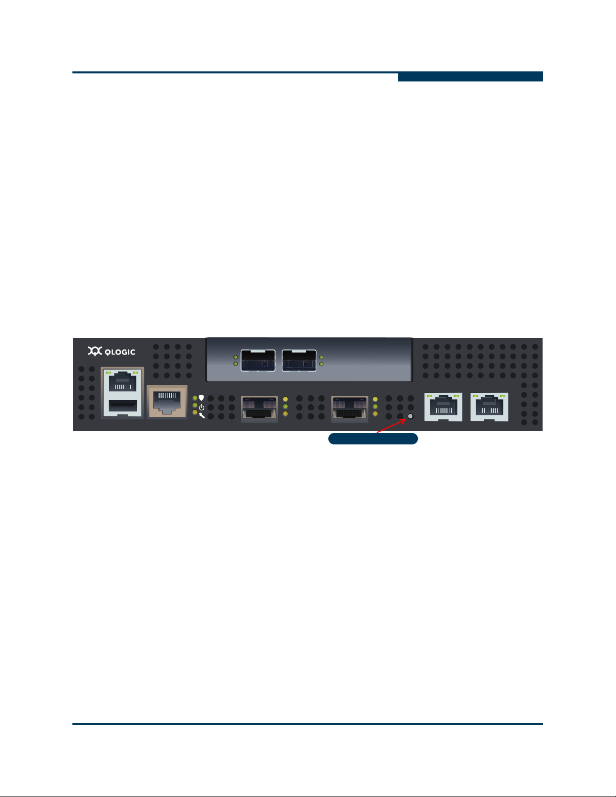
Maintenance Button
The maintenance button shown in Figure 1-7 is the only router blade control.
Press this button to reset the router blade or to recover it if it becomes disabled.
Introduction
iSR6250 Router Blades
Figure 1-7 Maintenance Button
The maintenance button is a multifunction momentary switch on the front panel. It
has the following functions:
Reset a Router Blade (see page 1-8)
Reset and Select Boot Image (see page 1-8)
Reset IP Address (see section page 1-8)
Enable DHCP (see section page 1-8)
Restore Factory Defaults (see page 1-9)
SN0051103-00 A 1-7

Introduction
iSR6250 Router Blades
Reset a Router Blade
To reset the router blade, use a pointed, nonmetallic tool to momentarily press and
release (less than two seconds) the maintenance button. The router responds as
follows:
1. All the router blade LEDs illuminate.
2. After about 2 seconds, the POST begins, turning off the heartbeat and
system fault LEDs.
3. When the POST is complete, the power LED is on and the heartbeat LED
flashes once per second.
Reset and Select Boot Image
You can reset the router using either the primary or secondary boot image:
Primary Image – To reset the router and select the primary boot image, use
a pointed, nonmetallic tool to press and hold the maintenance button until
the heartbeat LED flashes once, then release the button. The router will boot
from the primary boot image. The boot time is less than one minute.
S
Secondary Image – To reset the router and select the secondary boot
Reset IP Address
To reset the router and restore the maintenance port IP address to the default
(10.0.0.1), use a pointed, nonmetallic tool to press and hold the maintenance
button until the heartbeat LED flashes six times, then release the button. The
router boots and sets the maintenance port to IP address 10.0.0.1. The boot
time is less than one minute.
The IP address set by this method is not persistent; to make the change
persistent, use the command line interface (CLI) or SANsurfer Router Manager to
set the IP address. For more information, see the iSR6200 Router Manager
User's Guide and the iSR6200 Router CLI User's Guide.
Enable DHCP
To reset the router and configure the maintenance port to use DHCP to acquire its
IP address, use a pointed, nonmetallic tool to press and hold the maintenance
button until the heartbeat LED flashes seven times, then release the button. The
router boots and configures the maintenance port for DHCP. The boot time is less
than one minute.
image, use a pointed, nonmetallic tool to press and hold the maintenance
button until the heartbeat LED flashes twice, then release the button. The
heartbeat LED flashes twice. The router boots from secondary boot image.
The boot time is less than one minute.
1-8 SN0051103-00 A

A
MGMT IOIOI
FC1 FC2 GE1 GE1
GE4 GE3 iSR6240
Intelligent Storage Router
iSR6200 System
10GbE1 iSR6250
Intelligent Storage Router
10GbE2
8Gb (Yellow)
4Gb (Green)
2Gb (Amber)
Enabling DHCP by this method is not persistent; to make the change persistent,
use the command line interface (CLI) or SANsurfer Router Manager to enable
DHCP. For details, see the iSR6200 Router Manager User's Guide and the
iSR6200 Router CLI User's Guide.
Restore Factory Defaults
To reset the router and restore it to the factory default configuration, use a pointed,
nonmetallic tool to press the maintenance button and hold it until the heartbeat
LED flashes 20 times, then release the button. The router boots and is restored to
the factory defaults. The boot time is less than one minute.
The router does the following when restored to the factory defaults:
Clears all router log entries.
Resets all passwords.
Resets the maintenance port IP address to 10.0.0.1.
Disables the iSCSI ports and sets the IP address to 0.0.0.0.
Erases all presentations.
Introduction
iSR6250 Router Blades
Erases all discovered initiators and targets.
Fibre Channel Port LEDs
The iSR6250 router has two Fibre Channel ports. The ports are labeled FC1 and
FC2, as shown in Figure 1-8.
Figure 1-8 Fibre Channel LEDs
The port LEDs are located to the right of their respective ports and provide status
and activity information.
SN0051103-00 A 1-9

Introduction
iSR6250 Router Blades
Each port has three LEDs:
The yellow LED (top) shows activity for data passing through the port at
The green LED (middle) shows activity for data passing through the port at
The amber (bottom) LED shows activity for data passing through the port at
Table 1-3 describes the LED blink patterns and their meanings.
S
8-Gbps speed.
4-Gbps speed.
2-Gbps speed.
Table 1-3. Port LEDs
Activity
Power OFF
Power ON
Yellow LED
(8 Gbps)
OFF OFF OFF
ON ON ON
Green LED
(4 Gbps)
Amber LED
(2 Gbps)
(before firmware
initialization)
Power ON
Flashing Flashing Flashing
(after firmware
initialization)
Firmware initialization error
a
Online, 2-Gbps
Alternate Flashing.. Alternate Flashing.. AlternateFlashing..
OFF OFF ON/Flashing
link - I/O activity
Online, 4-Gbps
OFF ON/Flashing OFF
link - I/O activity
Online, 8-Gbps
ON/Flashing OFF OFF
link - I/O activity
Beacon
a
Yellow, green, and amber LEDs flash alternatively to indicate firmware initialization errors.
Flashing OFF Flashing
1-10 SN0051103-00 A

A
MGMT IOIOI
FC1 FC2 GE1 GE1
GE4 GE3 iSR6240
Intelligent Storage Router
iSR6200 System
10GbE1 iSR6250
Intelligent Storage Router
10GbE2
Activity Link Status
Fibre Channel Transceivers
Each port is served by a small form-factor pluggable (SFP) optical transceiver and
is capable of 1-, 2-, 4-, or 8-Gbps transmission. SFPs are hot-pluggable. User
ports can self-discover both the port type and transmission speed when
connected to public devices or switches.
The iSR6250 router supports SFP optical transceivers for the Fibre Channel ports.
A transceiver converts electrical signals to and from optical laser signals to
transmit and receive data. Duplex fiber optic cables plug into the transceivers,
which then connect to the devices. For example, a 1-Gbps/2-Gbps Fibre Channel
port can transmit at 1-Gbps or 2-Gbps; however, the transceiver must also be
capable of delivering these rates.
The SFP transceivers are hot pluggable. You can remove or install a transceiver
while the router is operating without harming the router or the transceiver.
However, this interrupts communication with the connected device. See page 3-7
for information about installing and removing SFP optical transceivers.
Gigabit Ethernet Port LEDs
Introduction
iSR6250 Router Blades
The Gigabit Ethernet ports shown in Figure 1-9 are RJ-45 connectors that provide
connection to an Ethernet SAN through a 100/1000 Base-T Ethernet cable. The
ports are labeled GE1 and GE2. Each of these ports supports connections that
run the iSCSI high-level TCP protocol.
Figure 1-9 Gigabit Ethernet Ports
These ports each have two LEDs:
The activity LED (green) lights up when the port transmits or receives data
over the Ethernet connection.
The link status LED (green) lights up continuously when the port establishes
an Ethernet connection.
SN0051103-00 A 1-11

Introduction
MGMT IOIOI
FC1 FC2 GE1 GE1
GE4 GE3 iSR6240
Intelligent Storage Router
iSR6200 System
10GbE1 iSR6250
Intelligent Storage Router
10GbE2
Activity
Activity Link Status
MGMT IOIOI
FC1 FC2 GE1 GE1
GE4 GE3 iSR6240
Intelligent Storage Router
iSR6200 System
10GbE1 iSR6250
Intelligent Storage Router
10GbE2
Activity
Activity
Serial Port
iSR6250 Router Blades
Ethernet Port— Management
The management Ethernet port shown in Figure 1-10 is an RJ-45 connector that
provides a connection to a management workstation through a 10/100 Base-T
Ethernet cable. The port is labeled MGMT..
Figure 1-10 Ethernet Management Port
A management workstation can be a Windows®, Solaris™, or a Linux™
workstation that configures and manages the router. You can manage the router
over an Ethernet connection using the SANsurfer Router Manager, command line
interface (CLI), or simple network management protocol (SNMP).
S
Serial Port
The management Ethernet port has two LEDs:
The link status LED (green) lights up continuously when the port establishes
an Ethernet connection.
The activity LED (green) lights up when the port transmits or receives data
over the Ethernet connection.
The iSR6250 router is equipped with an RS-232 serial port for maintenance
purposes. Figure 1-11 shows the serial port location, which is labeled IOIOI. You
can manage the router through the serial port using CLI.
Figure 1-11 Serial Port
1-12 SN0051103-00 A

A
Introduction
iSR6250 Router Blades
The serial port connection requires a standard eight-wire Ethernet cable and the
supplied dongle to convert the Ethernet RJ45 connector to a female DB9
connector. Table 1-4 defines the serial port pins for both the router’s RJ45
connector and the dongle DB9 connector.
Table 1-4. Serial Port Pin Identification
Dongle DB9
Pin Number
1 5 Data carrier detect (DCD)
2 6 Receive data (RxD)
3 3 Transmit data (TxD)
4 2 & 7 Data terminal ready (DTR)
5 4 Signal ground (GND)
6 5 Data set ready (DSR)
7 1 Request to send (RTS)
8 8 Clear to send (CTS)
9 NC Ring indicator (RI)
Router RJ45
Pin Number
Description
SN0051103-00 A 1-13

Introduction
iSR6250 Router Blades
Notes
S
1-14 SN0051103-00 A

2 Planning
This section describes how to plan for the iSR6250 router. The following sections
describe the devices and services you need to consider when planning to use the
iSR6250 router:
“Devices” on page 2-1
“Device Access” on page 2-2
“FC Switches Required for VPGroups” on page 2-2
“FC Performance” on page 2-2
“iSCSI Performance” on page 2-3
“Performance Tuning” on page 2-4
“High Availability” on page 2-7
“Management” on page 2-7
“Recovery” on page 2-7
“Services” on page 2-8
“Security” on page 2-8
Devices
When planning to use the router, consider the number of devices and the
anticipated demand. This determines the number of ports required and in turn the
number of routers.
The router uses SFP transceivers in the 8-Gbps Fibre Channel (FC) ports, but
some FC devices may not use the same transceivers. Consider whether the FC
device you want to connect the router to uses SFP or gigabit interface converters
(GBIC) transceivers, and choose fibre optic cables accordingly. Use LC-type
cable connectors for SFP transceivers and SC-type cable connectors for GBIC
transceivers. Also consider the transmission speed compatibility of your devices,
host bus adapters (HBAs), switches, and SFPs.
SN0051103-00 A 2-1

Planning
Device Access
Device Access
Consider device access needs within the FC and iSCSI SANs. Controlling access
to FC device LUNs requires mapping FC device LUNs to specific iSCSI initiators.
You may map LUNs to more than one initiator. Giving multiple initiators access to
a LUN requires access management.
Fibre Channel
The Fibre Channel ports automatically discover all FC target devices, whether
connected directly (loop) or by fabric (switch).
iSCSI
The iSCSI ports automatically present targets discovered on the Fibre Channel
ports. If the FC target’s LUN 0 is a controller LUN, it becomes accessible
(mapped) to all iSCSI initiators. All data LUNs are inaccessible until mapped. The
exception to this is if LUN 0 is a controller LUN, then it is mapped automatically to
allow for management of the FC target controller.
S
When an iSCSI initiator logs on, the router records the initiator’s iSCSI name and
IP address. The management interface [command line interface (CLI) and
SANsurfer Router Manager] uses the initiator information to simplify the mapping
process.
FC Switches Required for VPGroups
iSR6250 uses QLogic HBA technology and is compatible with all Fibre Channel
switches from Brocade, Cisco, McData, and QLogic. If you want to use more than
one VPGroup, you must use Fibre Channel Switches.
FC Performance
The iSR6250 router supports Fibre Channel service at transmission rates of 2, 4,
or 8 Gbps with a maximum frame size of 2148 bytes. Related performance
characteristics include the following:
Distance (see page 2-3)
Bandwidth (see page 2-3)
Latency (see page 2-3)
2-2 SN0051103-00 A

A
Distance
Consider the physical distance between Fibre Channel devices. Choose SFP
transceivers that are compatible with the cable type and distance.
Each Fibre Channel port is supported by a data buffer with a three-credit capacity;
that is, three maximum sized frames. For fibre optic cables, this enables full
bandwidth over the following approximate distances:
5 kilometers at 1 Gbps (0.6 credits/Km)
2.5 kilometers at 2 Gbps (1.2 credits/Km)
Beyond these distances, however, the connection loses some efficiency because
the transmitting port must wait for an acknowledgement before sending the next
frame.
Bandwidth
Bandwidth is a measure of the volume of data that can be transmitted at a given
transmission rate. A 1-Gbps/2-Gbps FC port can transmit or receive at nominal
rates of 1- or 2-Gbps, depending on the device to which it is connected. This
corresponds to actual bandwidth values of 106 MB and 212 MB, respectively.
Planning
iSCSI Performance
Latency
Latency is a measure of how fast a transaction travels through the router.
iSCSI Performance
The iSR6250 router supports Ethernet service at transmission rates of 1000-, 100or 10-Mbps with an MTU size of 1500 or 9000 (jumbo frames).
NOTE:
An MTU size greater than 1500 should only be used when the router is
connected to a 1000 Mbps Ethernet network.
Related performance characteristics include the following:
Distance
Bandwidth
Latency
Distance
Consider the physical distance between routers.This is usually measured in
round-trip delay. Round-trip delays range anywhere from less than 1 millisecond
to as great as 250 milliseconds.
SN0051103-00 A 2-3

Planning
Performance Tuning
Bandwidth
Bandwidth is a measure of the volume of data that can be transmitted at a given
transmission rate. WAN data rates range from 1.5 megabits per second (T1) to
greater than 600 megabits per second (OC-12).
Latency
Latency is a measure of how fast a transaction travels through the router and
LAN/WAN.
Performance Tuning
Proper configuration maximizes the router’s performance. Knowing the round trip
delay (distance between the router and iSCSI initiators) and WAN effective data
rate (connection type) allows you to tune the router for optimal performance. The
following tables provide TCP Window Size settings for specific WAN
environments. The TCP Window Size is configured as two parameters: Window
Size and Scaling Factor. See the iSR6200 Router Manager User's Guide and the
iSR6200 Router CLI User's Guide for configuring the TCP window size.
S
Table 2-1. T1: 1.554 Mbits/Sec
Round Trip Delay (ms) TCP Window Size (kBytes)
<= 41.5 8
<= 82.9 16
<= 165.8 32
<= 331.6 64
<= 663.2 128
<= 1326.5 256
<= 2652.9 512
2-4 SN0051103-00 A

A
Planning
Performance Tuning
Table 2-2. T3: 45Mbits/Sec
Round Trip Delay (ms) TCP Window Size (kbytes)
<= 1.4 8
<= 2.9 16
<= 5.7 32
<= 11.4 64
<= 22.9 128
<= 45.8 256
<= 91.6 512
<= 183.1 1024
<= 366.2 2048*
<= 732.5 4096*
*Supported in FCIP mode only.
Round Trip Delay (ms) TCP Window Size (kbytes)
<= 1.2 8
<= 2.5 16
<= 4.9 32
<= 9.9 64
<= 19.8 128
<= 39.5 256
<= 79.0 512
<= 158.0 1024
<= 316.1 2048*
<= 632.1 4096*
Table 2-3. OC1: 51 Mbits/Sec
*Supported in FCIP mode only.
SN0051103-00 A 2-5

Planning
Performance Tuning
S
Table 2-4. OC3: 156 Mbits/Sec
Round Trip Delay (ms) TCP Window Size (bytes)
<= 0.4 8
<= 0.8 16
<= 1.6 32
<= 3.3 64
<= 6.6 128
<= 13.2 256
<= 26.3 512
<= 52.7 1024
<= 105.4 2048
<= 210.7 4096
Table 2-5. OC12: 621 Mbits/Sec
Round Trip Delay (ms) TCP Window Size (bytes)
<= 0.1 8
<= 0.2 16
<= 0.4 32
<= 0.8 64
<= 1.6 128
<= 3.3 256
<= 6.6 512
<= 13.2 1024
<= 26.3 2048
<= 52.7 4096
2-6 SN0051103-00 A

A
High Availability
A dual-blade iSR6250 router supports high availability, which provides link-level,
switch-level, and blade-level failure protection. To make this effective, you must
connect the iSCSI hosts to both iSR6250 blades. For details, see “Connecting
iSCSI Hosts to your iSR6250” on page 4-13.
Management
The SANsurfer Router Manager application and CLI run on a management
workstation used to configure, control, and maintain the router. Support platforms
include Windows, Solaris, and Linux. The SANsurfer Router Manager application
is installed and executed on the workstation.
The router supports the following management interfaces:
SANsurfer Router Manager – Graphical user interface (GUI) application,
which runs on a management workstation (see the iSR6200 Router
Manager User's Guide).
Planning
High Availability
CLI – Command line interface, which runs on the router; users can access
SNMP – Provides router status, traps, and alerts (see Appendix B).
Recovery
You should have a process in place to recover from a possible router failure.
Consider the following when developing a recovery process for the router:
Save all firmware image files (updates) in a safe, well-known place, because
Save the router’s configuration (as a new file) after every configuration
Save the router’s LUN mappings (as a new file) after every mapping change,
the CLI via telnet or the serial port (see the iSR6200 Router CLI User's
Guide).
you may:
Want to revert to a previous firmware version.
Need the firmware image when adding a router to your site.
change, because you may want to revert to a previous configuration.
because you may:
Want to revert to a previous LUN mapping.
Want to duplicate the LUN mapping on a second router (for
redundancy).
SN0051103-00 A 2-7

Planning
Services
NOTE:
Services
You can configure your router to suit the demands of your environment using a
variety of router services. Familiarize yourself with the following router services
and determine which ones you need:
Telnet – Enables you to manage the router over a telnet connection.
Router management – Provides for out-of-band management of the router
Simple network management protocol (SNMP) – Enables you to monitor
Network time protocol (NTP) – Enables you to synchronize the router and
S
For more details on recovering a router blade, see “iSR6250 Chassis
Blades” on page 6-2.
with the SANsurfer Router Manager.
the router using third-party applications that use SNMP.
the workstation dates and times with an NTP server. NTP is disabled (not
configured) by default.
Security
File transfer protocol (FTP) – Enables you to transfer files rapidly between
the workstation and router using FTP.
Secure SHell (SSH) – Provides secure and encrypted connections to
traditionally non-encrypted services.
Passwords provide router security. The SANsurfer Router Manager requires a
password each time a user logs into the application. Once connected, the
SANsurfer Router Manager prompts for an administrative password before it
accepts configuration changes.
The CLI also requires the user to enter a user ID and password to start. CLI must
be in an admin session to perform any set operations. An admin session requires
a password.
The default password for both these management tools is password for the
default user ID of guest. The default administrative password is config.
Once logged on, you can change the password using the application’s security
features.
2-8 SN0051103-00 A

3 Installation
This section describes how to install and configure an iSR6250 router. It also
provides firmware installation instructions. For details, see the following topics:
“Site Requirements” on page 3-1
“Installing the iSR6250 Router” on page 3-2
“Firmware Installation” on page 3-14
Site Requirements
The following sections describe the requirements for installing a iSR6250 router:
Management Workstation (see page 3-1)
Power Requirements (see page 3-2)
Environmental Conditions (see page 3-2)
Management Workstation
The management workstation running the SANsurfer Router Manager must meet
the requirements listed in Table 3-1.
Table 3-1. Management Workstation Requirements
Item Description
Operating system One of the following:
Windows
Solaris 8/9/10
Linux
SuSE
Mac OS
Memory 256 MB or more
Disk space 150 MB per installation
Processor 500 MHz or faster
Hardware CD-ROM drive, RJ-45 Ethernet port, RS-232 serial port (optional)
SN0051103-00 A 3-1
®
2000/2003
®
Red Hat EL 3.x
®
Linux 9.0 Enterprise
®
X 10.3

Installation
Installing the iSR6250 Router
Table 3-1. Management Workstation Requirements (Continued)
Item Description
Internet browser One of the following:
Microsoft Internet Explorer 5.0 and later
Netscape Navigator
Mozilla
Java 2 runtime environment to support the web applet
Power Requirements
Power requirements for the iSR6250 router are 0.5 Amp at 100 VAC or 0.25 A at
240 VAC.
Environmental Conditions
Consider the factors that affect the climate in your facility, such as equipment heat
dissipation and ventilation. The router requires the following operating conditions:
®
4.72 and later
®
Firefox 1.02 and later
S
Operating temperature range: 5–40°C (41–104°F).
Relative humidity: 15–80 percent, non-condensing.
Installing the iSR6250 Router
Unpack the router, accessories, and documentation. The iSR6250 router is
shipped with the following components, shown in Figure 3-1.
iSR6250 router chassis with two blades installed
DB9 to RJ45 cable adapter
Power cable (6 foot black)
Rail Mounting Kit, part number 50990-00
WEEE Conformance Card
Readme Notice Card
China Optics and Cable SKUs Toxic Substance Table
To install the iSR6250 router:
1. Complete the pre-installation checklist (see page 3-3).
2. Mount the router (see page 3-5).
3. Install the transceivers (see page 3-7).
4. Connect the router to AC power (see page 3-8).
3-2 SN0051103-00 A

A
5. Connect the management workstation to the router (see page 3-9).
6. Configure the management workstation (see page 3-10).
7. Install the management application (see page 3-12).
8. Start the management application (see page 3-13).
9. Configure the router (see page 3-13).
10. Cable devices to the router (FC and iSCSI) (see page 3-14).
Pre-installation Check List
During the initial configuration process, the system prompts you to enter
information for each blade contained in the iSR6250 chassis. Use the space
provided in the following tables to record the IP addresses for each blade.
Table 3-2. Worksheet for Router Blade 1 (left) Parameters
Symbolic Name of the
iSR6250 Blade 1
Installation
Installing the iSR6250 Router
Management port IP
address, subnet mask,
and gateway (if not using
DHCP)
iSCSI port 1 IP address,
subnet mask, and gateway
(GE-1)
IP address of the iSNS
server for iSCSI port 1 (if
iSNS will be enabled)
iSCSI port 2 IP address,
subnet mask, and gateway
(GE-2)
IP address of the iSNS
server for iSCSI port 2 (if
iSNS will be enabled)
iSCSI port 3 IP address,
subnet mask, and gateway
for the 10GE-3 port
IP address of the iSNS
server for iSCSI port 3 (if
iSNS will be enabled)
SN0051103-00 A 3-3

Installation
Installing the iSR6250 Router
Table 3-2. Worksheet for Router Blade 1 (left) Parameters (Continued)
iSCSI port 4 IP address,
subnet mask, and gateway
for the10GE-4 port
IP address of the iSNS
server for iSCSI port 4 (if
iSNS will be enabled)
Table 3-3. Worksheet for Router Blade 2 (right) Parameters
Symbolic Name of the
iSR6250 Blade 2
Management port IP
address, subnet mask,
and gateway (if not using
DHCP)
S
iSCSI port 1 IP address,
subnet mask, and gateway
(GE-1)
IP address of the iSNS
server for iSCSI port 1 (if
iSNS will be enabled)
iSCSI port 2 IP address,
subnet mask, and gateway
(GE-2)
IP address of the iSNS
server for iSCSI port 2 (if
iSNS will be enabled)
iSCSI port 3 IP address,
subnet mask, and gateway
for the 10GE-3 port
IP address of the iSNS
server for iSCSI port 3 (if
iSNS will be enabled)
iSCSI port 4 IP address,
subnet mask, and gateway
for the 10GE-4 port
IP address of the iSNS
server for iSCSI port 4 (if
iSNS will be enabled)
3-4 SN0051103-00 A

A
1
6
3
4
7
2
5
6
Mount the Router
You can either place the router on a flat surface or mount it in a 19-inch Electronic
Industries Association (EIA) rack. See the product specification for weight and
dimensions. Rack mounting requires a QLogic rack mounting kit; contact QLogic
for more information.
If you mount the router in a closed or multi-unit rack assembly, make sure the
operating temperature inside the rack enclosure does not exceed the maximum
rated ambient temperature.
Figure 3-1 shows the iSR6200 Router Rail Kit components.
Installation
Installing the iSR6250 Router
1. Rack rail, inner (2)
2. Rack rail, outer (2)
3. Chassis rail (2)
a
For use only with racks with square holes.
4. Screw, flathead, 6-32 x 1/4 in. (8)
5. Screw, flathead, 10-32 x 1/4 in. (6)
6. Screw, panhead, 10-32 x 3/8 in. (10)
7. Washer, centering
a
(10)
Figure 3-1 Rail Kit Components
SN0051103-00 A 3-5

Installation
2
1
4
1
2
5
3
Installing the iSR6250 Router
Tools Required
Cross-head screwdriver, medium
WARNING!!
Heavier products should be placed near the bottom of a rack or cabinet. A top-heavy
rack can become unstable resulting in equipment damage or personal injury.
To avoid dropping the router, possibly causing personal injury or damage to the router,
hold the router and rail assembly firmly when sliding it out of the rack.
Install Chassis Rails
Install the chassis rails on the chassis using
three 10-32x1/4 screws to secure each rail.
The rail and the router have multiple mounting
holes to permit the desired setback.
S
Assemble and Install Rack Rails
Assemble the inner and outer rack rails and
secure them loosely with four 6-32 screws.
Extend each rack rail assembly to fit the inner
dimensions of the rack.
Fasten the rail assembly to the rack at both ends
with two 10-32x3/8 screws using the upper and
lower holes. If the rack holes are square, use a
centering washer with each screw.
1. Chassis rail 2. Screws, 10-32x1/4
1. Inner rack rail
2. Outer rack rail
3. Screw, 6-32
4. Screw, 10-32x3/8
5. Washer
3-6 SN0051103-00 A

A
1
1
Install the Chassis
Slide the chassis and rail assembly into the rack
rails.
Fasten the chassis to the rack with two 10-32 x
3/8 screws: one through each chassis rail flange.
Install the Transceivers
The router supports a variety of SFP transceivers.
Installation
Installing the iSR6250 Router
1. Screws, 10-32x3/8
To install a transceiver, insert the transceiver into the port and gently press
until it snaps in place.
To remove a transceiver, gently press the transceiver into the port to release
tension, then pull the release tab or lever and remove the transceiver.
Different transceiver manufacturers have different release mechanisms.
Consult the documentation for your transceiver.
NOTE:
The transceiver fits only one way. If the transceiver does not install under
gentle pressure, flip it over and try again.
SN0051103-00 A 3-7

Installation
MGMT IOIOI
FC1 FC2
MGMT IOIOI
FC1 FC2
10GbE1 iSR6250
Intelligent Storage Router
10GbE2
10GbE1 iSR6250
Intelligent Storage Router
10GbE2
Expansion Slot
Front Plate iSR6250 Blade 1 Front Plate iSR6250 Blade 2
Back Plate PCM for Blade 2
Back Plate PCM for Blade 1
Expansion Slot
PCM Status LED PCM Status LEDPower Connector Power Connector
Installing the iSR6250 Router
Connect the Router to AC Power
WARNING!!
This product is supplied with a 3-wire power cable and plug for the user’s
safety. Use this power cable in conjunction with a properly grounded outlet
to avoid electrical shock. An electrical outlet that is not correctly wired could
place hazardous voltage on metal parts of the router chassis. The customer
must make sure the outlet is correctly wired and grounded to prevent
electrical shock.
You may require a different power cable in some countries because the plug
on the cable supplied with the equipment will not fit your electrical outlet. In
this case, you must supply your own power cable. The cable must meet the
following requirements:
For 125 Volt electrical service: the cable must be rated at 10 Amps and
be approved by UL and CSA.
For 250 Volt electrical service: the cable must be rated at 10 Amps, meet
requirements of H05VV-F, and be approved by VDE, SEMKO, and
DEMKO.
Figure 3-1 shows the front and back plates of an iSR6250 router chassis that
contains two router blades with add-in ports installed for its model. Each power
cooling module (PCM) provides a power connector, as well as a Status LED.
S
Figure 3-1 iSR6250 Router Chassis — Front and Back Plates
Use Figure 3-1 to locate the power connector and PCM status LED for the blade
you’re configuring.
3-8 SN0051103-00 A

A
MGMT IOIOI
FC1 FC2 GE1 GE1
GE4 GE3 iSR6240
Intelligent Storage Router
iSR6200 System
10GbE1 iSR6250
Intelligent Storage Router
10GbE2
Management Port System Fault LED
RS232 Port Heartbeat LED Power LED
FC Ports
iSCSI Ports
Installation
Installing the iSR6250 Router
To power on the router:
1. Attach the AC power cord to the power connector, located on the back side
of the PCM connected directly behind the router blade.
2. Connect the opposite end of the power cord to a grounded AC wall outlet or
power strip.
3. Check the PCM power LED to make sure the fan is operational (green = OK,
yellow = no AC power).
Figure 3-2 shows the location of the ports and LEDs on one of the blades
contained within the iSR6250 unit that are referenced in the following
instructions.
Figure 3-2 iSR6250 Blade Ports and LEDs
4. Verify that the router’s input power LED is illuminated. The iSR6250 router
runs its self test and begins normal operation—this may take a minute.
5. Verify that the heartbeat LED is blinking (once per second) and that the
system fault LED is not illuminated.
If an error has occurred, the system fault LED will blink a pattern that indicates the
fault reason. For more information about error blink patterns, see page 5-3.
Connect the Management Workstation to the Router
You can manage the router using the SANsurfer Router Manager or the command
line interface (CLI). SANsurfer Router Manager requires an Ethernet connection
to the router. CLI can use an Ethernet connection or a serial connection. Choose
the router management method, then connect the management workstation to the
router in one of the following ways:
Indirect Ethernet connection from the management workstation to the router
RJ-45 connector through an Ethernet switch or hub. This requires a 10/100
Base-T straight cable.
SN0051103-00 A 3-9

Installation
Installing the iSR6250 Router
Direct Ethernet connection from the management workstation to the router
RJ-45 Ethernet connector. This requires a 10/100 Base-T crossover cable.
Serial port connection from the management workstation to the router
RS-232 serial port connector. This requires a 10/100 Base-T straight cable
and a dongle.
Configure the Management Workstation
The router comes from the factory with a default IP address (10.0.0.1). Prior to
product installation, follow the procedures based on your configuration method:
If you plan to configure the router through the management Ethernet port
(using the SANsurfer Router Manager or CLI via telnet), you must initially
configure the workstation as described in “Setting the Workstation IP
Address” on page 3-10.
If you plan to configure the router using the management COM port,
configure the workstation as described in “Configuring the Workstation
Serial Port” on page 3-11.
S
Setting the Workstation IP Address
The IP address of a new router is 10.0.0.1. To ensure that your workstation is
configured to communicate with the 10.0.0 subnet, refer to the following
instructions for your workstation:
Steps for different versions of Windows vary. For a Windows 2000
workstation, do the following:
a. From the Windows Start menu, select Settings>Control
Panel>Network and Dial-up Connections.
b. Click Make New Connection.
c. Click Connect to a private network through the Internet, then click
Next.
d. Enter 10.0.0.253 for the IP address.
For different versions of Windows, consult the Windows Help files.
For Linux or Solaris workstation, open a command window and enter the
following command, where <interface> is your interface name:
ifconfig <interface> ipaddress 10.0.0.253 netmask
255.255.255.0 up
3-10 SN0051103-00 A

A
Configuring the Workstation Serial Port
To configure the workstation serial port:
1. Connect the cable with RJ45 to DB9F adapter from a COM port on the
management workstation to the serial port on the router.
2. Configure the workstation serial port according to your platform. These steps
may vary according to the version of operating system you use:
For Windows:
a. Open the HyperTerminal application. From the Windows Start
menu, select Programs>
Accessories>HyperTerminal>HyperTerminal.
b. Enter a name for the router connection, choose an icon in the
Connection Description window, then click OK.
c. Enter the following COM Port settings in the COM Properties
window and click OK.
Bits per second – 115200
Data Bits – 8
Parity – None
Stop Bits – 1
Flow Control – None
Installation
Installing the iSR6250 Router
For Linux:
a. Set up minicom to use the serial port. Create or modify the
/etc/minirc.dfl file with the following content:
pr portdev/ttyS0
pu minit
pu mreset
pu mhangup
pr portdev/ttyS0 specifies port 0 on the workstation.
Choose the pr setting to match the workstation port to which you
connected the router.
b. Verify that all users have permission to run minicom. Review the
/etc/minicom.users file and confirm that the line ALL exists
or that there are specific user entries.
For Solaris – Modify the /etc/remote file to include the following
lines. /dev/term/a refers to serial port a. Choose the “dv” setting to
match the workstation port to which you connected the router.
\:dv=/dev/term/a:br#115200:el=^C^S^Q^U^D:ie=%$:oe=^
D:
3. Connect the router to the power (see page 3-13).
SN0051103-00 A 3-11

Installation
Installing the iSR6250 Router
Install SANsurfer Router Manager
You can manage the router using the SANsurfer Router Manager application. The
following sections describe how to install the application on either a Windows or
Linux workstation. See the iSR6200 Router Manager User's Guide for information
on how to use SANsurfer Router Manager.
Windows Installation
To install the SANsurfer Router Manager application from the QLogic
website to a PC workstation:
1. Close all programs currently running.
2. Go to the QLogic download site:
http://support.qlogic.com/support/drivers_software.aspx
3. Select the Intelligent Storage Routers icon.
4. Select iSR6250 in the product selection window and click Go.
5. Under the product name column, select the link to the SANsurfer Router
Manager for your operating system.
S
6. Read the license agreement and click Agree.
7. Follow the system prompts to uncompress and install the application.
Linux Installation
To install the SANsurfer Router Manager application from the QLogic
website to a Linux workstation:
1. Go to the QLogic download site:
2. Select the Intelligent Storage Routers icon.
3. Select iSR6250 in the product selection window and click Go.
4. Under the product name column, select the link to the SANsurfer Router
5. Read the license agreement and click Agree.
6. Save the file to your local system.
7. Uncompress the downloaded file and execute the Linux_x.xx.bin install
8. Follow the installation instructions.
http://support.qlogic.com/support/drivers_software.aspx
Manager for your operating system.
program.
3-12 SN0051103-00 A

A
Start SANsurfer Router Manager
For Windows, double-click the SANsurfer Router Manager shortcut, or select
SANsurfer Router Manager from the Start menu, depending on how you
installed the SANsurfer Router Manager application.
From a Windows command line, enter the following command:
<install_directory>SANsurfer_Router_Manager.exe
From a Linux command prompt, enter the following command:
<install_directory>./SANsurfer_Router_Manager
Configure the Router
You can configure the router using the SANsurfer Router Manager application or
the command line interface (CLI).
The SANsurfer Router Manager provides a Configuration Wizard you can use to
configure the GE ports. If either of the router’s GE ports have not been configured
(IP address is 0.0.0.0), the Configuration Wizard starts automatically when the
Router Manager first connects with the router. The system uses the information
collected in Table 3-2 and Ta bl e 3- 3.
Installation
Installing the iSR6250 Router
To configure the router using the command line interface:
1. Open a command window according to the type of workstation and
connection:
Ethernet (all platforms): Open a telnet session with the default router
IP address and log in to the router with the default account name and
password (guest/password):
telnet 10.0.0.1
username: guest
password: ********
Serial – Windows: Open the HyperTerminal application on a Windows
platform:
a. From the Windows Start menu, select Programs >
Accessories, HyperTerminal > HyperTerminal.
b. Select the connection you created earlier and click OK.
Serial – Linux: Open a command window and enter the following
command:
minicom
SN0051103-00 A 3-13

Installation
Firmware Installation
2. Open an admin session and enter the commands to set up both iSCSI ports
and the management interface. See the iSR6200 Router CLI User's Guide
for command descriptions.
QRouter #> admin start
Password : ******
QRouter (admin) #> set mgmt
………………………
QRouter (admin) #> set iscsi 1
………………………
QRouter (admin) #> set iscsi 2
………………………
Cable Devices to the Router
Connect cables to the SFP transceivers and their corresponding devices.
Devices can have SFP (or SFF) transceivers or gigabit interface converters
(GBIC). Choose the fiber optic cable with the connector combination that
matches the device being connected to the router:
S
LC-type duplex fiber optic cable connectors are designed for SFP
transceivers.
SC-type connectors are designed for GBICs.
OM-3 connectors are designed for 10Gb ports.
Firmware Installation
The router comes with current firmware installed. You can upgrade the firmware
from the management workstation as new firmware becomes available. You can
use the SANsurfer Router Manager application or the CLI to install new firmware.
WARNING!!
Installing new firmware disrupts the router blade connectivity since you must
reboot the router blade to activate the new firmware.
3-14 SN0051103-00 A

A
Firmware Installation
Using SANsurfer Router Manager to Install Firmware
To install firmware using the SANsurfer Router Manager:
1. Double-click the desired router in the topology display.
2. In the Firmware Upload window, click Select to navigate to and select the
firmware to upload it.
3. Click Start to begin the firmware load process. A message warns you that
the router will be reset to activate the firmware.
4. Click OK to continue firmware installation or click Cancel to cancel the
firmware installation.
Using the CLI to Install Firmware
To use CLI to install the firmware, transfer the firmware image file from a
workstation to the router. Then use the CLI image unpack command to install
the new firmware image:
1. At the workstation prompt, use the ftp command to go to the location on the
router where you want to transfer the firmware image. For example:
Installation
C:\fwImage>ftp 172.17.137.190
Connected to 172.17.137.190.
220 (none) FTP server (GNU inetutils 1.4.2) ready.
2. Enter your username and password. For example:
User (172.17.137.190:(none)): ftp
331 Guest login ok, type your name as password.
Password: ftp
230 Guest login ok, access restrictions apply.
3. At the ftp prompt, type bin to set binary mode. For example:
ftp> bin
200 Type set to I.
4. Use the put command to transfer the firmware image file from the
workstation to the router. For example:
ftp> put
200 PORT command successful.
150 Opening BINARY mode data connection for
'
isr-6200-3_0_0_5.bin'.
226 Transfer complete.
ftp: 4822816 bytes sent in 0.41Seconds
11878.86Kbytes/sec.
isr-6200-3_0_0_5.bin
5. Enter quit. The firmware image has been transferred to the router.
6. Log on to the router as an administrator.
SN0051103-00 A 3-15

Installation
Firmware Installation
7. Enter the following command from the router, where x stands for the
8. Enter reboot. The following message displays:
9. Type y to reboot the system.
S
firmware image name:
image unpack isr-62xx-x_x_x_x.bin
The following message displays:
Unpack Completed. Please reboot the system for FW to
take effect.
Are you sure you want to reboot the System (y/n):
3-16 SN0051103-00 A

4 Configuration
This section describes how to configure the iSR6250 router to support virtual port
groups (VPGs) and LUN mapping.
Some storage arrays limit the number of LUNs exposed to a host to 256 LUNs.
Each iSR6250 router blade supports up to four virtual port groups (VPGs), making
it possible for these storage arrays to present up to 1024 LUNs per blade.
When configuring VPGs on the iSR6250 router, follow these guidelines:
All Fibre Channel (FC) virtual ports from a single VPG must be part of only
one logical host on the storage array.
FC ports from different VPGs must not be part of the same logical host on
the storage array.
A given LUN can be presented to one and only one VPG. It can be
presented to other FC hosts, but only one VPG on a given iSR6250 router
(chassis).
The following sections describe how to configure VPGs and the Fibre Channel
arrays connected to them:
“Enabling Virtual Port Groups” on page 4-2
“Zoning Virtual Port Groups on the SAN” on page 4-9
“Configuring FC Array Hosts and LUN Assignments with the iSR6250” on
page 4-10
“Connecting iSCSI Hosts to your iSR6250” on page 4-13
“Controlling per Host LUN Access on the iSR6250” on page 4-20
SN0051103-00 A 4-1

Configuration
Enabling Virtual Port Groups
Enabling Virtual Port Groups
Each iSR6250 router blade has one virtual port group (VPG) enabled by default,
which gives the iSCSI hosts access to 256 LUNs. You can enable and configure
additional VPGs to give the iSCSI hosts access to more than 256 distinct LUNS
from a given FC Target Array.
Each blade has VPG 1 enabled by default; VPG 1 is the primary virtual port group
and cannot be disabled. Enabling additional virtual port groups creates additional
logical FC HBA initiator ports on the fabric. These ports act as separate FC HBA
host ports, and additional 256 LUNs can be presented to each of them. With all
four VPGs enabled, a single iSR6250 blade can access up to1024 LUNs from a
single target WWPN.
You can display virtual port group information using the show vpgroups
command in the CLI, as shown in the following example.
iSR6200 <1> (admin) #> show vpgroups
S
VpGroup Information
---------------------
Index 1
VpGroup Name VPGROUP_1
Status Enabled
WWPNs 21:00:00:c0:dd:13:16:f8
21:00:00:c0:dd:13:16:f9
Index 2
VpGroup Name VPGROUP_2
Status Disabled
WWPNs N/A
Index 3
VpGroup Name VPGROUP_3
Status Disabled
WWPNs N/A
Index 4
VpGroup Name VPGROUP_4
Status Disabled
WWPNs N/A
4-2 SN0051103-00 A

A
Configuration
Enabling Virtual Port Groups
Using the SANsurfer Router Manager, select one of the VPGroup icons in the left
panel to display that VPGroups information in the right panel.
Figure 4-1 SANsurfer Router Manager VPGroup
SN0051103-00 A 4-3

Configuration
Enabling Virtual Port Groups
You can enable or disable virtual port groups on your blade using either the GUI or
the CLI. The following example shows how to enable this VPGroups 2 and 3 using
the CLI set vpgroups command.
iSR6200 <1> (admin) #> set vpgroups
The following wizard will query for attributes before persisting
and activating the updated mapping in the system configuration.
If you wish to terminate this wizard before reaching the end of
the list
press 'q' or 'Q' and the ENTER key to do so.
Configuring VpGroup: 1
-------------------------
Status (0=Enable, 1=Disable) [Enabled ]
VpGroup Name (Max = 64 characters) [VPGROUP_1 ]
S
All attribute values for VpGroup 1 that have been changed will
now be saved.
Configuring VpGroup: 2
-------------------------
Status (0=Enable, 1=Disable) [Disabled ] 0
VpGroup Name (Max = 64 characters) [VPGROUP_2 ]
All attribute values for VpGroup 2 that have been changed will
now be saved.
Configuring VpGroup: 3
-------------------------
Status (0=Enable, 1=Disable) [Disabled ] 0
VpGroup Name (Max = 64 characters) [VPGROUP_3 ]
All attribute values for VpGroup 3 that have been changed will
now be saved.
Configuring VpGroup: 4
-------------------------
Status (0=Enable, 1=Disable) [Disabled ]
4-4 SN0051103-00 A

A
Configuration
Enabling Virtual Port Groups
All attribute values for VpGroup 4 that have been changed will
now be saved.
To enable or disable a VPGroup using the SANsurfer Router Manager:
1. Select the VPGroup in the system tree. The right panel displays information
about the selected VPGroup.
2. Select Enabled or Disabled from the Status drop-down menu. (See
Figure 4-2.)
Figure 4-2 Chassis Information for Selected VPGROUP
3. Click Save. A System Check dialog box prompts you to enter a password.
4. Enter the system password and click OK. The Set VPGroup message box
opens, as shown in Figure 4-3.
Figure 4-3 Set VPGroup Message Box
5. Click OK to close the message box.
SN0051103-00 A 4-5

Configuration
Enabling Virtual Port Groups
The following example shows CLI command output using an iSR6250 blade with
3 virtual port groups enabled. You can display information about the virtual port
groups configured on your iSR6250 using the show vpgroups command.
iSR6200 <R1> #> show vpgroups
iSR6200 <1> (admin) #> show vpgroups
VpGroup Information
---------------------
Index 1
VpGroup Name VPGROUP_1
Status Enabled
WWPNs 21:00:00:c0:dd:13:16:f8
21:00:00:c0:dd:13:16:f9
S
Index 2
VpGroup Name VPGROUP_2
Status Enabled
WWPNs 21:01:00:c0:dd:13:16:f8
21:01:00:c0:dd:13:16:f9
Index 3
VpGroup Name VPGROUP_3
Status Enabled
WWPNs 21:02:00:c0:dd:13:16:f8
21:02:00:c0:dd:13:16:f9
Index 4
VpGroup Name VPGROUP_4
Status Disabled
WWPNs N/A
In these examples, the second byte from the left (in bold text) denotes the virtual
port group ID, while the right-most byte (in italic text) denotes the physical FC port.
In these examples VPGs 1 through 3 have corresponding VPs with 00, 01, and 02
presented out of physical FC ports 0 and 1, with WWPNs ending in f8 and f9,
respectively.
4-6 SN0051103-00 A

Configuration
A
Enabling Virtual Port Groups
The following example shows the information grouped by physical FC port.
iSR6200 <1> (admin) #> show fc
FC Port Information
---------------------
FC Port 1
Port Status Enabled
Link Status Up
Current Link Rate 4Gb
Programmed Link Rate Auto
WWNN 20:00:00:c0:dd:13:16:f8 (VPGROUP_1)
WWPN 21:00:00:c0:dd:13:16:f8 (VPGROUP_1)
Port ID 0a-04-00 (VPGROUP_1)
WWNN 20:01:00:c0:dd:13:16:f8 (VPGROUP_2)
WWPN 21:01:00:c0:dd:13:16:f8 (VPGROUP_2)
Port ID 0a-04-01 (VPGROUP_2)
WWNN 20:02:00:c0:dd:13:16:f8 (VPGROUP_3)
WWPN 21:02:00:c0:dd:13:16:f8 (VPGROUP_3)
Port ID 0a-04-02 (VPGROUP_3)
Firmware Revision No. 4.05.00
Frame Size 2048
Execution Throttle 32768
Connection Mode Point-to-Point
Programmed Connection Option Loop Preferred
SFP Type 8Gb
FC Port 2
Port Status Enabled
Link Status Up
Current Link Rate 4Gb
Programmed Link Rate Auto
WWNN 20:00:00:c0:dd:13:16:f9 (VPGROUP_1)
WWPN 21:00:00:c0:dd:13:16:f9 (VPGROUP_1)
Port ID 0a-05-00 (VPGROUP_1)
WWNN 20:01:00:c0:dd:13:16:f9 (VPGROUP_2)
WWPN 21:01:00:c0:dd:13:16:f9 (VPGROUP_2)
Port ID 0a-05-01 (VPGROUP_2)
WWNN 20:02:00:c0:dd:13:16:f9 (VPGROUP_3)
WWPN 21:02:00:c0:dd:13:16:f9 (VPGROUP_3)
SN0051103-00 A 4-7

Configuration
Enabling Virtual Port Groups
Port ID 0a-05-02 (VPGROUP_3)
Firmware Revision No. 4.05.00
Frame Size 2048
Execution Throttle 32768
Connection Mode Point-to-Point
Programmed Connection Option Loop Preferred
SFP Type 8Gb
iSR6200 <1> (admin) #>
Notice also the VP index in the second byte from the left, and the FC port indicator
in the right-most byte.
To see this information using the SANsurfer Router Manager, select one of the
Fibre Channel ports, as shown in the following example.
S
Figure 4-4 FC Port Information Tab
NOTE:
For more details on using the application, use the SANsurfer Router
Manager Application Help or refer to the iSR6200 Router Manager User’s
Guide.
4-8 SN0051103-00 A

A
SAN A
iSR6250
FC Target Array
SAN B
Blade 1
Blade 2
21:00:00:c0:dd:13:16:f8
21:01:00:c0:dd:13:16:f8
21:02:00:c0:dd:13:16:f8
FC1
FC2
FC1
FC2
21:00:00:c0:dd:13:16:f9
21:01:00:c0:dd:13:16:f9
21:02:00:c0:dd:13:16:f9
21:00:00:c0:dd:13:17:02
21:01:00:c0:dd:13:17:02
21:02:00:c0:dd:13:17:02
21:00:00:c0:dd:13:17:03
21:01:00:c0:dd:13:17:03
21:02:00:c0:dd:13:17:03
FC1 A0
A1
B0
B1
Controller A
Controller B
FC2
FC1
FC2
A0
B1
21:00:00:c0:dd:13:16:f8
21:01:00:c0:dd:13:16:f8
21:02:00:c0:dd:13:16:f8
A0
B1
21:00:00:c0:dd:13:17:02
21:01:00:c0:dd:13:17:02
21:02:00:c0:dd:13:17:02
A1
B0
A1
B0
Zone 6250 Blade 1 A Zone 6250 Blade 2 A
Zone 6250 Blade 1 B Zone 6250 Blade 2 B
21:00:00:c0:dd:13:16:f9
21:01:00:c0:dd:13:16:f9
21:02:00:c0:dd:13:16:f9
21:00:00:c0:dd:13:17:03
21:01:00:c0:dd:13:17:03
21:02:00:c0:dd:13:17:03
Zoning Virtual Port Groups on the SAN
Zoning Virtual Port Groups on the SAN
When connecting the iSR6250 for high availability, connect one FC port from each
blade to each of your fabrics (see Figure 4-5). This topology provides link-level,
switch-level, and blade-level failure protection. To make this effective, you must
connect the iSCSI hosts to both iSR6250 blades. For details, see “Connecting
iSCSI Hosts to your iSR6250” on page 4-13.
Configuration
Figure 4-5 High-Availability, Dual Blades, Dual FC Switches
SN0051103-00 A 4-9

Configuration
Configuring FC Array Hosts and LUN Assignments with the iSR6250
Configuring FC Array Hosts and LUN Assignments with the iSR6250
When configuring FC array hosts, you must treat each iSR6250 virtual port group
(VPG) as its own unique FC host within the virtualized storage array. This means if
you have only one VPG enabled, the iSR6250 will have only one host entity. If you
enable two more VPGs,
storage array.
When using the iSR6250 in a high availability configuration, assign each VPG
from the second
VPG from blade 1.
iSR6250 blade in the same chassis to the same host entity as
the iSR6250 will present three separate host entities to your
S
Figure 4-6 Correct VPG Assignments for High Availability Configuration
Do not put VPG ports in Host entities with other FC hosts.
4-10 SN0051103-00 A

A
iSR6200
Storage Array
Blade 1
21:00:00:c0:dd:13:16:f8
21:01:00:c0:dd:13:16:f8
21:02:00:c0:dd:13:16:f8
21:00:00:c0:dd:13:16:f8
21:00:00:c0:dd:13:16:f9
FC1
FC2
Host Entities
Host Entity 0
21:01:00:c0:dd:13:16:f8
21:01:00:c0:dd:13:16:f9
Host Entity 1
21:02:00:c0:dd:13:16:f8
21:02:00:c0:dd:13:16:f9
Host Entity 2
21:00:00:c0:dd:13:16:f9
21:01:00:c0:dd:13:16:f9
21:02:00:c0:dd:13:16:f9
LUN 1
LUN 2
LUN 3
LUN 4
Configuration
Configuring FC Array Hosts and LUN Assignments with the iSR6250
When assigning LUNs to your VPG host entities, you must not assign the same
LUN to two VPG Host entities. Figure 4-7 shows a valid LUN presentation. Each
LUN is presented to only one VPG. Any of these LUNs can be presented to any
number of other FC hosts on the array; but can be presented to one and only one
VPG of the iSR6250.
Figure 4-7 Correctly Assigning LUNs to your VPG Host Entities
SN0051103-00 A 4-11

Configuration
iSR6200
Storage Array
Blade 1
21:00:00:c0:dd:13:16:44
21:00:00:c0:dd:13:16:45
FC1
FC2
Host Entities
Host Entity 0
21:01:00:c0:dd:13:16:44
21:01:00:c0:dd:13:16:45
Host Entity 1
21:02:00:c0:dd:13:16:44
21:02:00:c0:dd:13:16:45
Host Entity 2
21:02:00:c0:dd:13:16:44
21:02:00:c0:dd:13:16:45
Host Entity 3
LUN 1
LUN 2
LUN 3
LUN 4
LUN 5
21:00:00:c0:dd:13:16:44
21:01:00:c0:dd:13:16:44
21:02:00:c0:dd:13:16:44
21:02:00:c0:dd:13:16:44
21:00:00:c0:dd:13:16:45
21:01:00:c0:dd:13:16:45
21:02:00:c0:dd:13:16:45
21:02:00:c0:dd:13:16:45
Configuring FC Array Hosts and LUN Assignments with the iSR6250
Figure 4-8 shows presenting LUN 3 incorrectly. If an iSCSI host logged into both
VPG0 and VPG1 it will have access to LUN 3 through 2 Virtual port groups. This is
invalid and will lead to serious problems.
S
Figure 4-8 Incorrectly Presenting LUN 3
Presenting the LUN at different LUN indexes for each VP will confuse the iSCSI
host MPIO software because it will see the same LUN WWLUNID at two different
indexes. This would cause the MPIO driver to panic or crash. Without an MPIO
driver,
you want to avoid.
4-12 SN0051103-00 A
the system could corrupt data on the LUN, without crashing. This is something

A
Connecting iSCSI Hosts to your iSR6250
Connecting iSCSI Hosts to your iSR6250
Upon logging into a Fibre Channel target WWPN, an iSR6250 blade will present
an iSCSI Target for iSCSI initiators to connect to. This target is defined by its
iSCSI Qualified Name (IQN) string. To connect iSCSI initiators to Fibre Channel
targets through the iSR6250 correctly, it is important to understand the
composition of the iSCSI target IQN string.
The following example shows the anatomy of a sample IQN string from an
iSR6250 router:
iqn.2004-08.com.qlogic:isr6250.0834e00019.b1.01.20030020c2075970
Configuration
1
1. Vendor name and registration date
2. Product Name
3. iSR6250 Chassis Serial Number
4. Blade (b1 or b2)
5. VPGroup (01 through 04)
6. FC target WWPN
Notice that the IQN string does not contain any information about which iSR6250
physical iSCSI port you are connecting to. iSCSI load balancing and failover are
handled by the iSCSI host and not on the iSR6250.
Also notice the IQN string does not contain any information about which physical
Fibre Channel port on the iSR6250 the FC target device is attached through.
2 3
4
5
6
SN0051103-00 A 4-13

Configuration
Connecting iSCSI Hosts to your iSR6250
You can display the complete list of IQN strings your iSR6250 is presenting with
the show presented_targets command in the CLI. For example:
iSR6200 <1> (admin) #> show presented_targets
Presented Target Information
------------------------------
iSCSI Presented Targets
-------------------------
Name
iqn.2004-08.com.qlogic:isr6200.0834e00019.r1.01.20030020c2075970
Alias
<MAPS TO>
WWNN 10:00:00:20:c2:07:59:70
WWPN 20:03:00:20:c2:07:59:70
S
Name
iqn.2004-08.com.qlogic:isr6200.0834e00019.r1.01.21040020c2075970
Alias
<MAPS TO>
WWNN 10:00:00:20:c2:07:59:70
WWPN 21:04:00:20:c2:07:59:70
4-14 SN0051103-00 A

A
Configuration
Connecting iSCSI Hosts to your iSR6250
To display presented target information using the SANsurfer Router Manager,
expand the iSCSI Presented Targets tree and select the device, as shown in
Figure 4-9.
Figure 4-9 Selecting the iSCSI Presented Targets in the SANsurfer Router
Manager
SN0051103-00 A 4-15

Configuration
Connecting iSCSI Hosts to your iSR6250
Enabling additional VPGroups can create multiple IQN strings for the same Fibre
Channel WWPN. The example below shows two FC target WWPNs and three VP
groups. This leads to a total of six presented iSCSI qualified names. For
information about how to enable and configure additional VPGroups, see
“Enabling Virtual Port Groups” on page 4-2.
iSR6200 <1> (admin) #> show targets
Target Information
--------------------
WWNN 10:00:00:20:c2:07:59:70
WWPN 20:03:00:20:c2:07:59:70
Port ID 0a-02-00
State Online
WWNN 10:00:00:20:c2:07:59:70
WWPN 21:04:00:20:c2:07:59:70
Port ID 0a-03-00
State Online
S
iSR6200 <1> #> show vpgroups
VpGroup Information
---------------------
Index 1
VpGroup Name VPGROUP_1
Status Enabled
WWPNs 21:00:00:c0:dd:13:16:f8
21:00:00:c0:dd:13:16:f9
Index 2
VpGroup Name VPGROUP_2
Status Enabled
WWPNs 21:01:00:c0:dd:13:16:f8
21:01:00:c0:dd:13:16:f9
Index 3
VpGroup Name VPGROUP_3
Status Enabled
4-16 SN0051103-00 A

A
Configuration
Connecting iSCSI Hosts to your iSR6250
WWPNs 21:02:00:c0:dd:13:16:f8
21:02:00:c0:dd:13:16:f9
Index 4
VpGroup Name VPGROUP_4
Status Disabled
WWPNs N/A
iSR6200 <1> (admin) #> show presented_targets
Presented Target Information
------------------------------
iSCSI Presented Targets
-------------------------
Name
iqn.2004-08.com.qlogic:isr6200.0834e00019.r1.01.20030020c2075970
Alias
<MAPS TO>
WWNN 10:00:00:20:c2:07:59:70
WWPN 20:03:00:20:c2:07:59:70
Name
iqn.2004-08.com.qlogic:isr6200.0834e00019.r1.01.21040020c2075970
Alias
<MAPS TO>
WWNN 10:00:00:20:c2:07:59:70
WWPN 21:04:00:20:c2:07:59:70
Name
iqn.2004-08.com.qlogic:isr6200.0834e00019.r1.02.20030020c2075970
Alias
<MAPS TO>
WWNN 10:00:00:20:c2:07:59:70
WWPN 20:03:00:20:c2:07:59:70
Name
iqn.2004-08.com.qlogic:isr6200.0834e00019.r1.02.21040020c2075970
Alias
SN0051103-00 A 4-17

Configuration
iSR6200
iSCSI Host
Storage Array
Blade 1
21:00:00:c0:dd:13:16:f8
21:01:00:c0:dd:13:16:f8
21:02:00:c0:dd:13:16:f8
21:00:00:c0:dd:13:16:f8
21:00:00:c0:dd:13:16:f9
FC1
FC2
Host Entities
Host Entity 0
21:01:00:c0:dd:13:16:f8
21:01:00:c0:dd:13:16:f9
Host Entity 1
21:02:00:c0:dd:13:16:f8
21:02:00:c0:dd:13:16:f9
Host Entity 2
21:00:00:c0:dd:13:16:f9
21:01:00:c0:dd:13:16:f9
21:02:00:c0:dd:13:16:f9
LUN 1
LUN 2
LUN 1
LUN 2
LUN 3
LUN 4
20:03:00:20:c2:07:59:70
SAN
LAN
iqn.2004-08.com:isr6200.0834e00019.r1.00.20030020c2075970
iqn.2004-08.com:isr6200.0834e00019.r1.00.20030020c2075970
iqn.2004-08.com:isr6200.0834e00019.r1.00.20030020c2075970
Connecting iSCSI Hosts to your iSR6250
<MAPS TO>
WWNN 10:00:00:20:c2:07:59:70
WWPN 21:04:00:20:c2:07:59:70
Name
iqn.2004-08.com.qlogic:isr6200.0834e00019.r1.03.20030020c2075970
Alias
<MAPS TO>
WWNN 10:00:00:20:c2:07:59:70
WWPN 20:03:00:20:c2:07:59:70
Name
iqn.2004-08.com.qlogic:isr6200.0834e00019.r1.03.21040020c2075970
Alias
<MAPS TO>
WWNN 10:00:00:20:c2:07:59:70
WWPN 21:04:00:20:c2:07:59:70
S
iSCSI host LUN access will be determined by the specific iSCSI target the host
connects to, and the LUNs that VPG has access to from the storage array. Pay
special attention to the VPG index of the IQN string you are logging into; it
determines which group of LUNs on the Storage Array your host can access.
Figure 4-10 Host Access to LUNs on Storage Array
4-18 SN0051103-00 A

A
iSR6200
iSCSI Host
Storage Array
Blade 1
21:00:00:c0:dd:13:16:f8
21:01:00:c0:dd:13:16:f8
21:02:00:c0:dd:13:16:f8
21:00:00:c0:dd:13:16:f8
21:00:00:c0:dd:13:16:f9
FC1
FC2
Host Entities
Host Entity 0
21:01:00:c0:dd:13:16:f8
21:01:00:c0:dd:13:16:f9
Host Entity 1
21:02:00:c0:dd:13:16:f8
21:02:00:c0:dd:13:16:f9
Host Entity 2
21:00:00:c0:dd:13:16:f9
21:01:00:c0:dd:13:16:f9
21:02:00:c0:dd:13:16:f9
LUN 1
LUN 2
LUN 3
LUN 3
LUN 4
20:03:00:20:c2:07:59:70
SAN
LAN
iqn.2004-08.com:isr6200.0834e00019.r1.00.20030020c2075970
iqn.2004-08.com:isr6200.0834e00019.r1.00.20030020c2075970
iqn.2004-08.com:isr6200.0834e00019.r1.00.20030020c2075970
iSR6200
iSCSI Host
Storage Array
Blade 1
21:00:00:c0:dd:13:16:f8
21:01:00:c0:dd:13:16:f8
21:02:00:c0:dd:13:16:f8
21:00:00:c0:dd:13:16:f8
21:00:00:c0:dd:13:16:f9
FC1
FC2
Host Entities
Host Entity 0
21:01:00:c0:dd:13:16:f8
21:01:00:c0:dd:13:16:f9
Host Entity 1
21:02:00:c0:dd:13:16:f8
21:02:00:c0:dd:13:16:f9
Host Entity 2
21:00:00:c0:dd:13:16:f9
21:01:00:c0:dd:13:16:f9
21:02:00:c0:dd:13:16:f9
LUN 1
LUN 2
LUN 3 LU N 4
LUN 3
LUN 4
20:03:00:20:c2:07:59:70
SAN
LAN
iqn.2004-08.com:isr6200.0834e00019.r1.00.20030020c2075970
iqn.2004-08.com:isr6200.0834e00019.r1.00.20030020c2075970
iqn.2004-08.com:isr6200.0834e00019.r1.00.20030020c2075970
Configuration
Connecting iSCSI Hosts to your iSR6250
iSCSI host has logged into iSCSI target for VPG0. Host can access VPG0 LUNS
#1 and #2 from storage array.
Figure 4-11 iSCSI Host Logged into iSCSI Target for VPG0
iSCSI host has logged into iSCSI target for VPG1. Host can access VPG1 LUN #3
from storage array.
Figure 4-12 iSCSI Host Logged into iSCSI Target for VPG1
iSCSI host has logged into iSCSI targets for both VPG1 and VPG2. Host can
SN0051103-00 A 4-19
access both VPG1 and VPG2 LUNs #3 and #4.

Configuration
Host accessible LUNs
Storage Array
21:00:00:c0:dd:13:16:f8
21:01:00:c0:dd:13:16:f8
21:02:00:c0:dd:13:16:f8
21:00:00:c0:dd:13:16:f8
21:00:00:c0:dd:13:16:f9
iSR6200
Blade 1
FC1
FC2
Host Entities
Host Entity 0
21:01:00:c0:dd:13:16:f8
21:01:00:c0:dd:13:16:f9
Host Entity 1
21:02:00:c0:dd:13:16:f8
21:02:00:c0:dd:13:16:f9
Host Entity 2
21:00:00:c0:dd:13:16:f9
21:01:00:c0:dd:13:16:f9
21:02:00:c0:dd:13:16:f9
LUN 1
LUN 2
LUN 3
LUN 4
LUN 5
LUN 6
iqn.2004-08.com:isr6200.0834e00019.r1.00.20030020c2075970
iqn.2004-08.com:isr6200.0834e00019.r1.00.20030020c2075970
iqn.2004-08.com:isr6200.0834e00019.r1.00.20030020c2075970
Log-In
Controlling per Host LUN Access on the iSR6250
S
Controlling per Host LUN Access on the iSR6250
The iSR6250 allows multiple iSCSI initiators to connect to a single FC target
through a given VPG. Controlling individual LUN access for each iSCSI host
requires LUN mapping devices connected through the iSR6250.
NOTE:
Before proceeding with this section, be sure you have read and understand
the previous sections of this chapter.
Figure 4-13 shows that even after logging into the VPG0 iSCSI target, the host
cannot access data LUNs on the storage array. To allow the iSCSI host access to
each LUN, you must configure the iSR6250 using either the SANsurfer Router
Manager or the command line interface (CLI).
4-20 SN0051103-00 A
Figure 4-13 Logging into Target Before LUN Mapping

A
Configuration
Controlling per Host LUN Access on the iSR6250
The following example shows how to map the LUN targets with initiators using CLI
commands.
iSR6200 <1> (admin) #> lunmask add
Index Mapped (WWNN,WWPN/iSCSI Name)
----- ------ ----------------------
0 Yes iqn.1991-05.com.microsoft:winhaz38
Please select an Initiator from the list above ('q' to quit): 0
Index (VpGroup Name)
----- --------------
1 VPGROUP_1
2 VPGROUP_2
3 VPGROUP_3
4 VPGROUP_4
Multiple VpGroups are currently 'ENABLED'.
Please select a VpGroup from the list above ('q' to quit): 1
Index (WWNN,WWPN/iSCSI Name)
----- ----------------------
0 50:06:01:60:c1:e0:0d:a2,50:06:01:60:41:e0:0d:a2
1 50:06:01:60:c1:e0:0d:a2,50:06:01:68:41:e0:0d:a2
Please select a Target from the list above ('q' to quit): 0
Index (LUN/VpGroup) Vendor
----- ------------- ------
1 1/VPGROUP_1 DGC
2 2/VPGROUP_1 DGC
3 3/VPGROUP_1 DGC
Please select a LUN to present to the initiator ('q' to quit): 1
All attribute values that have been changed will now be saved.
SN0051103-00 A 4-21

Configuration
Host accessible LUNs
Storage Array
21:00:00:c0:dd:13:16:f8
21:01:00:c0:dd:13:16:f8
21:02:00:c0:dd:13:16:f8
21:00:00:c0:dd:13:16:f8
21:00:00:c0:dd:13:16:f9
iSR6200
Blade 1
FC1
FC2
Host Entities
Host Entity 0
21:01:00:c0:dd:13:16:f8
21:01:00:c0:dd:13:16:f9
Host Entity 1
21:02:00:c0:dd:13:16:f8
21:02:00:c0:dd:13:16:f9
Host Entity 2
21:00:00:c0:dd:13:16:f9
21:01:00:c0:dd:13:16:f9
21:02:00:c0:dd:13:16:f9
LUN 1
LUN 2
LUN 3
LUN 4
LUN 5
LUN 6
iqn.2004-08.com:isr6200.0834e00019.r1.00.20030020c2075970
iqn.2004-08.com:isr6200.0834e00019.r1.00.20030020c2075970
iqn.2004-08.com:isr6200.0834e00019.r1.00.20030020c2075970
Log-In
LUN 1
Controlling per Host LUN Access on the iSR6250
Figure 4-14 shows the effect of mapping an initiator to LUN 1 using the CLI
commands shown in the previous example.
S
Figure 4-14 Logging into Target After Mapping LUN 1
You can accomplish the same LUN mapping using the SANsurfer Router
Manager’s Presentation Wizard.
To map LUN 1 to an initiator using the Router Manager:
1. Select Presentation Wizard from the Wizards menu.
2. Expand the router blade node (identified by its IP address), the virtual port
group node, and the device node.
3. Select LUN1 as shown in Figure 4-15, then click Next.
4-22 SN0051103-00 A

A
Configuration
Controlling per Host LUN Access on the iSR6250
Figure 4-15 Target Presentation/LUN Mapping Wizard - LUN Selection
4. Select the check box next to the description of the initiators you want the
LUNS mapped to, as shown in Figure 4-16.
Figure 4-16 Target Presentation/LUN Mapping Wizard - Select the Initiators
5. Click Next. The Confirm Changes dialog box appears, displaying the
configuration changes made to the selected LUN, as shown in Figure 4-17.
SN0051103-00 A 4-23

Configuration
Controlling per Host LUN Access on the iSR6250
S
Figure 4-17 Target Presentation/LUN Mapping Wizard - Confirm Changes
6. Review the configuration changes, then click Next. The LUN Masking
Configuration Status dialog box appears, along with the Security Check
dialog box, as shown in Figure 4-18.
Figure 4-18 Security Check Dialog Box
4-24 SN0051103-00 A
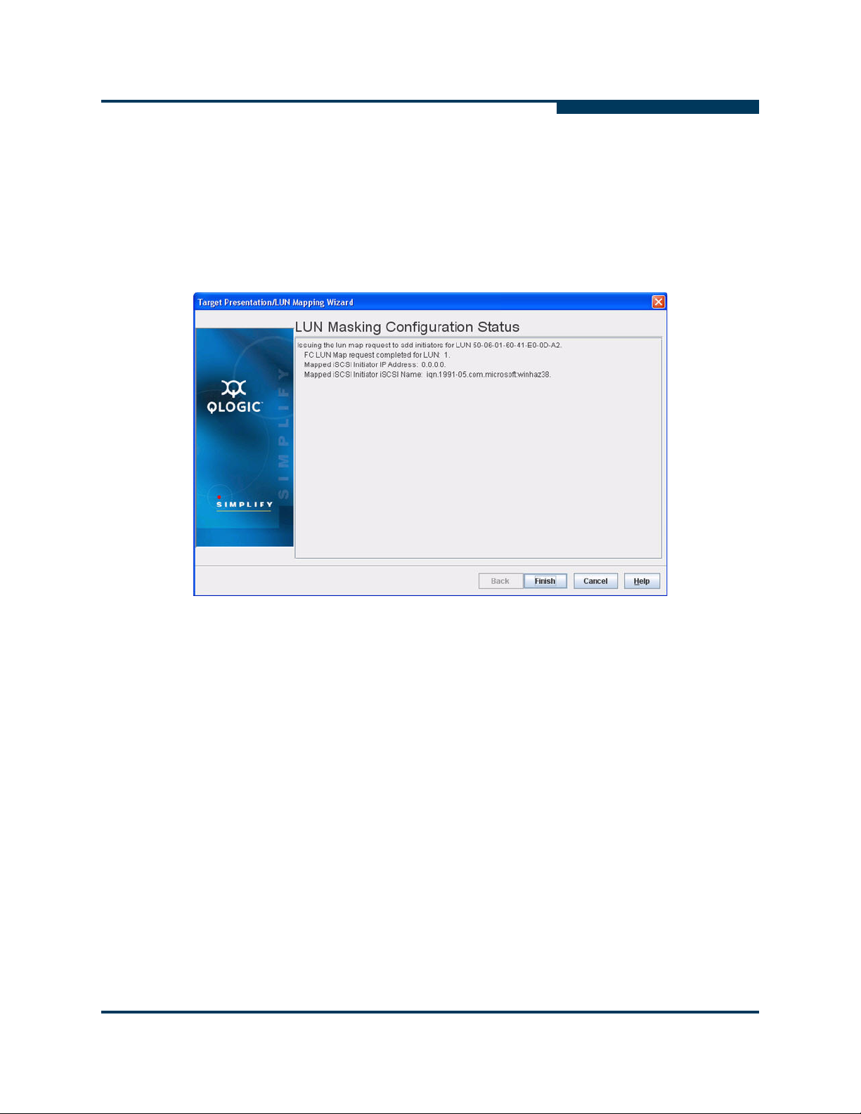
A
Configuration
Controlling per Host LUN Access on the iSR6250
7. In the Security Check dialog box, enter the system password, then click OK.
NOTE:
The default password is config.
The LUN Masking Configuration screen displays the mapping requests, as
shown in Figure 4-19.
Figure 4-19 Target Presentation/LUN Mapping Wizard - LUN Masking
Configuration Status
8. Verify the completion status displayed on the LUN Masking Configuration
Status screen, then click Finish. The wizard screen closes.
You can map additional LUNs using either the SANsurfer Router Manager or the
command line interface (CLI). The iSCSI host cannot access mapped LUNs until it
logs into the presented target for the corresponding iSR6250 virtual port group
and Fibre Channel target WWPN.
SN0051103-00 A 4-25

Configuration
Host accessible LUNs
Storage Array
21:00:00:c0:dd:13:16:f8
21:01:00:c0:dd:13:16:f8
21:02:00:c0:dd:13:16:f8
21:00:00:c0:dd:13:16:f8
21:00:00:c0:dd:13:16:f9
iSR6200
Blade 1
FC1
FC2
Host Entities
Host Entity 0
21:01:00:c0:dd:13:16:f8
21:01:00:c0:dd:13:16:f9
Host Entity 1
21:02:00:c0:dd:13:16:f8
21:02:00:c0:dd:13:16:f9
Host Entity 2
21:00:00:c0:dd:13:16:f9
21:01:00:c0:dd:13:16:f9
21:02:00:c0:dd:13:16:f9
LUN 1
LUN 2
LUN 3
LUN 4
LUN 5
LUN 6
iqn.2004-08.com:isr6200.0834e00019.r1.00.20030020c2075970
iqn.2004-08.com:isr6200.0834e00019.r1.00.20030020c2075970
iqn.2004-08.com:isr6200.0834e00019.r1.00.20030020c2075970
LUN 1
LUN 3
LUN 4
LUN 5
Log-In
Controlling per Host LUN Access on the iSR6250
Figure 4-20 uses color coding to identify the LUN Mapping that became available
after the host logged into the presented targets.
S
If you plan to allow all iSCSI hosts unrestricted access to all discovered FC LUNs,
you can completely disable LUN mapping using either the SANsurfer Router
Manager or CLI commands.
4-26 SN0051103-00 A
Figure 4-20 Logging In with Mapped LUNs

Configuration
A
Controlling per Host LUN Access on the iSR6250
The following example shows how to do this using the set system CLI
command. The red text shows entering the command that enables the LUN
mapping.
iSR6200 <1> (admin) #> set system
A list of attributes with formatting and current values will follow.
Enter a new value or simply press the ENTER key to accept the current value.
If you wish to terminate this process before reaching the end of the list
press 'q' or 'Q' and the ENTER key to do so.
WARNING:
If enabled by operator, the Symbolic Name can be embedded as part of the
iSCSI Name. Changes to the iSCSI name will be effective after a reboot.
Only valid iSCSI name characters will be accepted. Valid characters include
alphabetical (a-z, A-Z), numerical (0-9), colon, hyphen, and period.
Changes to the Settings below will be effective after a reboot.
System Symbolic Name (Max = 64 characters) [Blade-1 ]
Embed Symbolic Name (0=Enable,1=Disable) [Disabled ]
Target Presentation Mode (0=Auto, 1=Manual) [Auto ]
Lun Mapping (0=Enable, 1=Disable) [Disabled ]
Controller Lun AutoMap (0=Enable, 1=Disable) [Enabled ]
Target Access Control (0=Enable, 1=Disable) [Disabled ]
Telnet (0=Enable, 1=Disable) [Enabled ]
SSH (0=Enable, 1=Disable) [Enabled ]
All attribute values that have been changed will now be saved.
NOTE:
You must reboot the router to change the LUN mapping status, whether
you’re enabling it or disabling it.
If you are running the iSR6250 in a High-Availability configuration, make
sure both blades have the same setting.
SN0051103-00 A 4-27

Configuration
Controlling per Host LUN Access on the iSR6250
Figure 4-21 shows how to select the enable option for LUN masking on iSR6250
blade 1. To apply these changes, you must click Save, enter the system
password, and reboot the router blade.
S
Figure 4-21 Enabling LUN Mask Mode
4-28 SN0051103-00 A

A
Host accessible LUNs
Storage Array
21:00:00:c0:dd:13:16:f8
21:01:00:c0:dd:13:16:f8
21:02:00:c0:dd:13:16:f8
21:00:00:c0:dd:13:16:f8
21:00:00:c0:dd:13:16:f9
iSR6200
Blade 1
FC1
FC2
Host Entities
Host Entity 0
21:01:00:c0:dd:13:16:f8
21:01:00:c0:dd:13:16:f9
Host Entity 1
21:02:00:c0:dd:13:16:f8
21:02:00:c0:dd:13:16:f9
Host Entity 2
21:00:00:c0:dd:13:16:f9
21:01:00:c0:dd:13:16:f9
21:02:00:c0:dd:13:16:f9
LUN 1
LUN 2
LUN 3
LUN 4
LUN 5
LUN 6
iqn.2004-08.com:isr6200.0834e00019.r1.00.20030020c2075970
iqn.2004-08.com:isr6200.0834e00019.r1.00.20030020c2075970
iqn.2004-08.com:isr6200.0834e00019.r1.00.20030020c2075970
LUN 1
LUN 3
LUN 2
LUN 4
LUN 5
LUN 6
Configuration
Controlling per Host LUN Access on the iSR6250
Figure 4-22 shows host LUN access with LUN Masking set to disabled.
Figure 4-22 Host LUN Access with LUN Masking Disabled
NOTE:
The iSR6250 router can access LUNs only after the host logs into iSR6250
Presented iSCSI target(s).
SN0051103-00 A 4-29

Configuration
Controlling per Host LUN Access on the iSR6250
Notes
S
4-30 SN0051103-00 A

5 Diagnostics and
MGMT IOIOI
FC1 FC2 GE1 GE1
GE4 GE3 iSR6240
Intelligent Storage Router
iSR6200 System
10GbE1 iSR6250
Intelligent Storage Router
10GbE2
Power LEDSystem Fault LEDHeartbeat LED
Troubleshooting
Diagnostic information about the router is available through the chassis LEDs and
the port LEDs. Diagnostic information is also available through the SANsurfer
Router Manager and Command Line Interface (CLI) event logs and error displays.
This section describes the following types of diagnostics:
Chassis Diagnostics
Power-On Self-Test Diagnostics (see page 5-2)
LED Blink Patterns (see page 5-3)
This section also describes how to use maintenance mode to recover a disabled
router (see page 5-5).
Chassis Diagnostics
Figure 5-1 shows the chassis diagnostic LEDs.
Figure 5-1 Router Blade Diagnostic LEDs
Chassis Diagnostic LEDs
This section describes the following conditions:
Input Power LED is Off (see page 5-2)
System Fault LED is On (see page 5-2)
SN0051103-00 A 5-1

Diagnostics and Troubleshooting
Power-On Self-Test Diagnostics
Input Power LED is Off
The input power LED lights up to show that the router logic circuitry is receiving
proper voltages. If the input power LED is off, do the following:
Inspect power cord and connectors. Is the cord unplugged? Is the cord or
connector damaged?
Yes – Make necessary corrections or repairs. If the condition remains,
continue.
No – Continue.
Inspect AC power source. Is the power source delivering the proper voltage?
Yes – Continue.
No – Make the necessary repairs. If the condition remains, continue.
Replace the router.
System Fault LED is On
S
The System fault LED will blink a specific pattern to indicate the problem. If the system
fault LED lights up, take necessary actions (see page 5-3).
Power-On Self-Test Diagnostics
The router performs a series of tests as part of its power-on procedure. The POST
diagnostic program performs the following tests:
Memory
FLASH validation
PCI device discovery
Management Ethernet port
5-2 SN0051103-00 A

A
LED Blink Patterns
The heartbeat and system fault LEDs show the operational status of the router.
When the POST completes with no errors, these LEDs blink at a steady rate of
once per second. When the router is in maintenance mode, the heartbeat and
system fault LEDs are on continuously.
Diagnostics and Troubleshooting
LED Blink Patterns
All other
an error blink pattern for the conditions listed in Table 5-1.
OFF OK - Operational
3 Blinks, followed by pause System error
4 Blinks, followed by pause Management port IP address conflict
5 Blinks, followed by pause Over temperature
system fault blink patterns show critical errors. The heartbeat LED shows
Table 5-1. System Fault LED Blink Patterns
System Fault LED Condition
Heartbeat Blink Pattern
A blink pattern on the heartbeat LED of one second ON followed by one second
OFF means that the router is operating normally. The heartbeat LED shows this
pattern when the router firmware is operational
System Error Blink Pattern
.
The system fault LED generates a three-blink pattern (once per second) followed
by a two second pause to indicate a system error.
SN0051103-00 A 5-3

Diagnostics and Troubleshooting
LED Blink Patterns
Management Port IP Address Conflict Blink Pattern
The system fault LED generates a four-blink pattern (once per second) followed
by a two second pause when the router detects an IP address conflict on the
management Ethernet port.
You can clear the IP address conflict blinking using the CLI or SANsurfer Router
Manager. Use the beacon OFF function.
Over-Temperature Blink Pattern
The system fault LED generates a five-blink pattern (once per second) followed by
a two second pause when the router is in an over-temperature condition. That is,
the air temperature inside the router is over the failure temperature of 70
(158
°F).
S
°C
If the system fault LED shows the over temperature blink pattern, do the following:
Inspect the chassis air vents. Are the intake and exhaust vents clear?
Yes – Continue
No – Remove any debris from the fan intake and exhaust if necessary.
If the condition remains, continue.
Consider the ambient air temperature near the router and clearance around
the router. Make necessary corrections. If the condition remains, open a
command line window and log on to the router. Enter the shutdown
command, then power down the router. Contact your authorized
maintenance provider.
5-4 SN0051103-00 A

A
Recovering a Router
You may have to recover a router for one of the following reasons:
The password was changed and has been forgotten.
The router’s management IP address is unknown.
To recover the router’s password, reset the password to the default by using the
maintenance button (see page 1-7).
You can recover the router’s IP address using either of the following methods:
Connect to the serial console port (see page 1-12), then use the CLI set
mgmt command to reconfigure the management port (see the iSR6200 CLI
User’s Guide).
Use the maintenance button to reset the management port’s IP to the factory
default of 10.0.0.1 (see page 1-7).
Diagnostics and Troubleshooting
Recovering a Router
SN0051103-00 A 5-5

Diagnostics and Troubleshooting
Recovering a Router
Notes
S
5-6 SN0051103-00 A

6 Removal/Replacement
This section describes how to remove and replace the following field replaceable
units (FRUs):
“SFP Transceivers” on page 6-1
“iSR6250 Chassis Blades” on page 6-2
“Power and Cooling Modules” on page 6-6
SFP Transceivers
You can remove and replace the SFP transceivers while the iSR6250 router is
operating without damaging the router or the transceiver. However, this interrupts
transmission on the affected port until you install the transceiver.
To remove a transceiver, gently press the transceiver into the port to release
the tension, then pull the release tab or lever and remove the transceiver.
Different transceiver manufacturers have different release mechanisms.
Consult the documentation for your transceiver.
To install a transceiver, insert it into the port and gently press until it snaps in
place.
NOTE:
The SFP transceiver fits only one way. If the SFP does not install under
gentle pressure, flip it over and try again.
SN0051103-00 A 6-1

Removal/Replacement
iSR6250 Chassis Blades
iSR6250 Chassis Blades
The iSR6250 router provides an enhanced facility you can use to replace any
blade in the field. When you replace a blade, it automatically restores all the
configuration data from the other blade.
The following sections show how to remove and replace a failed blade in the
iSR6250 dual-blade chassis:
“Removing the Failed Blade” on page 6-2
“Installing a New Replacement Blade” on page 6-4
Removing the Failed Blade
To remove a failed blade from an iSR6250 chassis:
1. Log all iSCSI initiators out of the iSR6250 blade you are replacing prior to
replacing the iSR6250 router blade.
2. Disconnect all cables from the iSR6250 blade you are replacing. This
includes Fibre Channel, iSCSI, management, Ethernet, and serial cables.
S
Figure 6-1 iSR6250 Router Blade with Cables Disconnected
6-2 SN0051103-00 A

A
(1)
(2)
Removal/Replacement
iSR6250 Chassis Blades
3. Remove the old blade from the chassis. Figure 6-2 shows how to release
the latch and pull down on the lever on the right-hand side (1), then pull
straight back on the handle (2).
Figure 6-2 Removing the Chassis Blade
SN0051103-00 A 6-3

Removal/Replacement
iSR6250 Chassis Blades
Installing a New Replacement Blade
Before replacing a blade for a dual-blade router installation, you must first remove
it (as described on page 6-2).
To install a replacement blade in an iSR6250 chassis with a dual blade:
1. Unlatch the lever on the new blade prior to inserting it into the chassis, as
shown in Figure 6-3.
S
Figure 6-3 Unlatching the Lever on the New Blade
6-4 SN0051103-00 A

A
(1)
(2)
Removal/Replacement
iSR6250 Chassis Blades
2. Insert the new blade into the chassis slot. Figure 6-4 shows how to push the
blade straight into the chassis (1), then seat the blade onto the chassis
mid-plane by pushing the right side lever up and latching it into place (2).
The blade will power on and boot up.
Figure 6-4 Inserting the New Blade into the Chassis Slot
3. Reconnect all cables to the new blade.
SN0051103-00 A 6-5

Removal/Replacement
Power and Cooling Modules
Power and Cooling Modules
Each iSR6250 chassis blade has a power and cooling module (PCM), located on
the back side of the chassis. Each PCM consists of one power supply, three fans,
and one external status LED.
The PCM’s external status LED shows its status:
Green = GOOD status, indicating that the PCM is running as expected.
Amber = FAULT status, indicating that the PCM has failed.
You can remove and replace a failed PCM as described in the following sections:
“Removing the Failed PCM” on page 6-6
“Installing a New PCM” on page 6-8
Removing the Failed PCM
To remove a failed PCM from the iSR6250 chassis:
S
1. Locate the failed PCM unit on the back side of the iSR6250 chassis. A failed
PCM unit displays an amber color status LED.
Figure 6-5 shows the back side of two PCMs installed in a chassis
configured with two iSR6250 chassis blades. The PCM on the left side
displays its fault indicator in amber, which indicates a FAULT status. The
PCM on the right side displays its fault indicator in green, which indicates a
GOOD status.
Figure 6-5 Back Side of Two PCMs with Fault (left) and Good (right) Status
Indicators
2. Check the second (GOOD) PCM to make sure it is ready to support storage
connectivity while you’re replacing the failed PCM unit. Make sure the
second PCM’s power cable is connected to the cable with the other end
plugged into a live power source and that it displays a green status LED.
CAUTION!
Failure to verify the functionality of the second PCM can result in lost
host storage connectivity.
6-6 SN0051103-00 A

A
(1)
(2)
Removal/Replacement
Power and Cooling Modules
3. Remove the power cable from the failed PCM unit. The LED will remain
amber even after the removing the power cable.
4. Release the chassis latch on the left side of the unplugged PCM. As shown
in Figure 6-6, pull down on the lever to unseat the PCM (1), then remove the
PCM by pulling straight back on the handle (2).
Figure 6-6 Removing the Failed PCM
SN0051103-00 A 6-7

Removal/Replacement
Power and Cooling Modules
Installing a New PCM
To install a replacement PCM in the iSR6250 chassis:
1. Before you insert the new PCM into the chassis, unlatch the lever on the
new PCM (see Figure 6-7.)
S
Figure 6-7 Unlatching Lever on New PCM
6-8 SN0051103-00 A

A
(1)
(2)
Removal/Replacement
Power and Cooling Modules
2. Insert the replacement PCM into the iSR6250 chassis. As shown in
Figure 6-6, push the PCM straight into the chassis (1) and make sure the
PCM is properly seated into the chassis mid-plane by pushing the lever up
and locking the latch in the up position (2). The PCM fans will turn on and
the LED should show an amber status.
Figure 6-8 Inserting the Replacement PCM
3. Connect the power cable to the newly inserted PCM. Its status LED should
change from amber to green within 5 seconds.
Figure 6-9 Back Side of Two PCMs - Both with Good Status Indicators
4. Verify that the airflow through both PCMs is in the same direction.
SN0051103-00 A 6-9

Removal/Replacement
Power and Cooling Modules
Notes
S
6-10 SN0051103-00 A
 Loading...