

Page 1

iSR6152
Router Manager
User’s Guide
ISR645610-00 B
Page 2

iSR6152 Router Manager
User’s Guide
Information furnished in this manual is believed to be accurate and reliable. However, QLogic Corporation assumes no
responsibility for its use, nor for any infringements of patents or other rights of third parties which may result from its
use. QLogic Corporation reserves the right to change product specifications at any time without notice. Applications
described in this document for any of these products are for illustrative purposes only. QLogic Corporation makes no
representation nor warranty that such applications are suitable for the specified use without further testing or
modification. QLogic Corporation assumes no responsibility for any errors that may appear in this document.
Document Revision History
Revision A, August 10, 2011
Revision B, November 22, 2011
Changes Sections Affected
Updated references to the utility name from
“SANsurfer iSCSI/FC Router Manager” and
“iSCSI/FC Router Manager” to SANsurfer Router
Manager.
Updated screen shots to show the new utility
name, SANsurfer Router Manager, in the title bar:
Figure 1-3
Figure 2-1
All
“Viewing SANsurfer Router Manager Information”
on page 1-9
“Main Window” on page 2-2
ii ISR645610-00 B
Page 3

Table of Contents
Preface
Intended Audience . . . . . . . . . . . . . . . . . . . . . . . . . . . . . . . . . . . . . . . . . . . . ix
What’s in this Guide . . . . . . . . . . . . . . . . . . . . . . . . . . . . . . . . . . . . . . . . . . . ix
What’s in the Help System . . . . . . . . . . . . . . . . . . . . . . . . . . . . . . . . . . . . . . x
Related Materials . . . . . . . . . . . . . . . . . . . . . . . . . . . . . . . . . . . . . . . . . . . . . x
Documentation Conventions . . . . . . . . . . . . . . . . . . . . . . . . . . . . . . . . . . . . xi
License Agreements. . . . . . . . . . . . . . . . . . . . . . . . . . . . . . . . . . . . . . . . . . . xiii
Technical Support. . . . . . . . . . . . . . . . . . . . . . . . . . . . . . . . . . . . . . . . . . . . . xiii
Training . . . . . . . . . . . . . . . . . . . . . . . . . . . . . . . . . . . . . . . . . . . . . . . . xiii
Contact Information . . . . . . . . . . . . . . . . . . . . . . . . . . . . . . . . . . . . . . . xiv
Knowledge Database . . . . . . . . . . . . . . . . . . . . . . . . . . . . . . . . . . . . . xiv
1 Getting Started
System Requirements . . . . . . . . . . . . . . . . . . . . . . . . . . . . . . . . . . . . . . . . . 1-1
Connecting the Management Workstation to the Router . . . . . . . . . . . . . . . 1-2
Connecting the Hardware . . . . . . . . . . . . . . . . . . . . . . . . . . . . . . . . . . 1-2
Setting the Workstation IP Address. . . . . . . . . . . . . . . . . . . . . . . . . . . 1-2
Configuring the Router Ports. . . . . . . . . . . . . . . . . . . . . . . . . . . . . . . . 1-3
Updating the Firmware . . . . . . . . . . . . . . . . . . . . . . . . . . . . . . . . . . . . 1-3
Starting SANsurfer Router Manager. . . . . . . . . . . . . . . . . . . . . . . . . . . . . . . 1-4
Starting SANsurfer Router Manager on Windows . . . . . . . . . . . . . . . . 1-5
Starting SANsurfer Router Manager on Linux or Solaris. . . . . . . . . . . 1-5
Starting SANsurfer Router Manager on Macintosh . . . . . . . . . . . . . . . 1-5
Connecting SANsurfer Router Manager to the Router. . . . . . . . . . . . . . . . . 1-6
Getting Help . . . . . . . . . . . . . . . . . . . . . . . . . . . . . . . . . . . . . . . . . . . . . . . . . 1-7
Viewing the Help System. . . . . . . . . . . . . . . . . . . . . . . . . . . . . . . . . . . 1-7
Specifying the Help Browser . . . . . . . . . . . . . . . . . . . . . . . . . . . . . . . . 1-8
Viewing SANsurfer Router Manager Information . . . . . . . . . . . . . . . . 1-9
Setting Security . . . . . . . . . . . . . . . . . . . . . . . . . . . . . . . . . . . . . . . . . . . . . . 1-10
Refreshing the Host Configuration . . . . . . . . . . . . . . . . . . . . . . . . . . . . . . . . 1-12
Exiting SANsurfer Router Manager . . . . . . . . . . . . . . . . . . . . . . . . . . . . . . . 1-13
ISR645610-00 B iii
Page 4

iSR6152 Router Manager
User’s Guide
2 Understanding the User Interface
Main Window . . . . . . . . . . . . . . . . . . . . . . . . . . . . . . . . . . . . . . . . . . . . . . . . 2-2
Menu Bar . . . . . . . . . . . . . . . . . . . . . . . . . . . . . . . . . . . . . . . . . . . . . . . . . . . 2-3
File Menu. . . . . . . . . . . . . . . . . . . . . . . . . . . . . . . . . . . . . . . . . . . . . . . 2-3
View Menu. . . . . . . . . . . . . . . . . . . . . . . . . . . . . . . . . . . . . . . . . . . . . . 2-4
Settings Menu . . . . . . . . . . . . . . . . . . . . . . . . . . . . . . . . . . . . . . . . . . . 2-4
Wizards Menu . . . . . . . . . . . . . . . . . . . . . . . . . . . . . . . . . . . . . . . . . . . 2-4
Help Menu . . . . . . . . . . . . . . . . . . . . . . . . . . . . . . . . . . . . . . . . . . . . . . 2-6
Toolbar . . . . . . . . . . . . . . . . . . . . . . . . . . . . . . . . . . . . . . . . . . . . . . . . . . . . . 2-6
Shortcut Menus . . . . . . . . . . . . . . . . . . . . . . . . . . . . . . . . . . . . . . . . . . . . . . 2-6
Tree Pane. . . . . . . . . . . . . . . . . . . . . . . . . . . . . . . . . . . . . . . . . . . . . . . . . . . 2-10
Router Tree . . . . . . . . . . . . . . . . . . . . . . . . . . . . . . . . . . . . . . . . . . . . . 2-10
Services Tree . . . . . . . . . . . . . . . . . . . . . . . . . . . . . . . . . . . . . . . . . . . 2-13
Status Icons and Text . . . . . . . . . . . . . . . . . . . . . . . . . . . . . . . . . . . . . . . . . . 2-13
Router Tree Icons . . . . . . . . . . . . . . . . . . . . . . . . . . . . . . . . . . . . . . . . 2-13
Router. . . . . . . . . . . . . . . . . . . . . . . . . . . . . . . . . . . . . . . . . . . . . 2-14
FC and iSCSI Ports . . . . . . . . . . . . . . . . . . . . . . . . . . . . . . . . . . 2-14
VP Groups . . . . . . . . . . . . . . . . . . . . . . . . . . . . . . . . . . . . . . . . . 2-14
Discovered FC and iSCSI Initiators . . . . . . . . . . . . . . . . . . . . . . 2-15
FC and iSCSI Discovered Targets . . . . . . . . . . . . . . . . . . . . . . . 2-15
iSCSI Presented Targets . . . . . . . . . . . . . . . . . . . . . . . . . . . . . . 2-16
FCIP Routes . . . . . . . . . . . . . . . . . . . . . . . . . . . . . . . . . . . . . . . . 2-16
Arrays . . . . . . . . . . . . . . . . . . . . . . . . . . . . . . . . . . . . . . . . . . . . . 2-16
Services Tree Icons. . . . . . . . . . . . . . . . . . . . . . . . . . . . . . . . . . . . . . . 2-16
Data Migration Jobs . . . . . . . . . . . . . . . . . . . . . . . . . . . . . . . . . . 2-17
Data Migration Groups . . . . . . . . . . . . . . . . . . . . . . . . . . . . . . . . 2-17
3 Viewing Router Information
Router iSR6152 . . . . . . . . . . . . . . . . . . . . . . . . . . . . . . . . . . . . . . . . . . . . . . 3-2
Information. . . . . . . . . . . . . . . . . . . . . . . . . . . . . . . . . . . . . . . . . . . . . . 3-2
Basic Information . . . . . . . . . . . . . . . . . . . . . . . . . . . . . . . . . . . . 3-3
Management Information . . . . . . . . . . . . . . . . . . . . . . . . . . . . . . 3-6
NTP Server Information . . . . . . . . . . . . . . . . . . . . . . . . . . . . . . . 3-8
Security. . . . . . . . . . . . . . . . . . . . . . . . . . . . . . . . . . . . . . . . . . . . 3-9
SNMP Management . . . . . . . . . . . . . . . . . . . . . . . . . . . . . . . . . . . . . . 3-10
SNMP Configuration. . . . . . . . . . . . . . . . . . . . . . . . . . . . . . . . . . 3-11
Enabled SNMP Trap Receivers . . . . . . . . . . . . . . . . . . . . . . . . . 3-11
Features . . . . . . . . . . . . . . . . . . . . . . . . . . . . . . . . . . . . . . . . . . . . . . . 3-12
iv ISR645610-00 B
Page 5

iSR6152 Router Manager
User’s Guide
FC Ports . . . . . . . . . . . . . . . . . . . . . . . . . . . . . . . . . . . . . . . . . . . . . . . . . . . . 3-12
Information. . . . . . . . . . . . . . . . . . . . . . . . . . . . . . . . . . . . . . . . . . . . . . 3-13
Advanced Configuration . . . . . . . . . . . . . . . . . . . . . . . . . . . . . . . . . . . 3-14
Statistics . . . . . . . . . . . . . . . . . . . . . . . . . . . . . . . . . . . . . . . . . . . . . . . 3-14
Performance . . . . . . . . . . . . . . . . . . . . . . . . . . . . . . . . . . . . . . . . . . . . 3-15
iSCSI Ports. . . . . . . . . . . . . . . . . . . . . . . . . . . . . . . . . . . . . . . . . . . . . . . . . . 3-17
Information. . . . . . . . . . . . . . . . . . . . . . . . . . . . . . . . . . . . . . . . . . . . . . 3-17
iSCSI Port Information . . . . . . . . . . . . . . . . . . . . . . . . . . . . . . . . 3-18
iSCSI Port Network Settings. . . . . . . . . . . . . . . . . . . . . . . . . . . . 3-18
iSNS . . . . . . . . . . . . . . . . . . . . . . . . . . . . . . . . . . . . . . . . . . . . . . 3-19
Advanced Configuration . . . . . . . . . . . . . . . . . . . . . . . . . . . . . . . . . . . 3-20
Statistics . . . . . . . . . . . . . . . . . . . . . . . . . . . . . . . . . . . . . . . . . . . . . . . 3-22
VP Groups . . . . . . . . . . . . . . . . . . . . . . . . . . . . . . . . . . . . . . . . . . . . . . . . . . 3-23
Discovered FC Initiators . . . . . . . . . . . . . . . . . . . . . . . . . . . . . . . . . . . . . . . . 3-24
Information. . . . . . . . . . . . . . . . . . . . . . . . . . . . . . . . . . . . . . . . . . . . . . 3-24
LUN List. . . . . . . . . . . . . . . . . . . . . . . . . . . . . . . . . . . . . . . . . . . . . . . . 3-25
Discovered iSCSI Initiators. . . . . . . . . . . . . . . . . . . . . . . . . . . . . . . . . . . . . . 3-25
Information. . . . . . . . . . . . . . . . . . . . . . . . . . . . . . . . . . . . . . . . . . . . . . 3-26
LUN List. . . . . . . . . . . . . . . . . . . . . . . . . . . . . . . . . . . . . . . . . . . . . . . . 3-27
FC Discovered Targets . . . . . . . . . . . . . . . . . . . . . . . . . . . . . . . . . . . . . . . . . 3-27
FC Presented Targets . . . . . . . . . . . . . . . . . . . . . . . . . . . . . . . . . . . . . 3-28
iSCSI Presented Target List . . . . . . . . . . . . . . . . . . . . . . . . . . . . . . . . 3-28
Information. . . . . . . . . . . . . . . . . . . . . . . . . . . . . . . . . . . . . . . . . . . . . . 3-29
iSCSI Presented Target . . . . . . . . . . . . . . . . . . . . . . . . . . . . . . . . . . . . 3-30
Discovered LUN Information . . . . . . . . . . . . . . . . . . . . . . . . . . . . . . . . 3-31
iSCSI Discovered Targets . . . . . . . . . . . . . . . . . . . . . . . . . . . . . . . . . . . . . . 3-32
Information. . . . . . . . . . . . . . . . . . . . . . . . . . . . . . . . . . . . . . . . . . . . . . 3-32
Arrays . . . . . . . . . . . . . . . . . . . . . . . . . . . . . . . . . . . . . . . . . . . . . . . . . . . . . . 3-34
iSCSI Presented Targets . . . . . . . . . . . . . . . . . . . . . . . . . . . . . . . . . . . . . . . 3-35
Information. . . . . . . . . . . . . . . . . . . . . . . . . . . . . . . . . . . . . . . . . . . . . . 3-35
FCIP Routes. . . . . . . . . . . . . . . . . . . . . . . . . . . . . . . . . . . . . . . . . . . . . . . . . 3-37
FCIP Route Info. . . . . . . . . . . . . . . . . . . . . . . . . . . . . . . . . . . . . . . . . . 3-38
Statistics . . . . . . . . . . . . . . . . . . . . . . . . . . . . . . . . . . . . . . . . . . . . . . . 3-42
4 Viewing Service Information
Router iSR6152 . . . . . . . . . . . . . . . . . . . . . . . . . . . . . . . . . . . . . . . . . . . . . . 4-1
Data Migration Info . . . . . . . . . . . . . . . . . . . . . . . . . . . . . . . . . . . . . . . 4-2
ISR645610-00 B v
Page 6

iSR6152 Router Manager
User’s Guide
Data Migration Jobs . . . . . . . . . . . . . . . . . . . . . . . . . . . . . . . . . . . . . . . . . . . 4-3
Active Data Migration Jobs . . . . . . . . . . . . . . . . . . . . . . . . . . . . . . . . . 4-3
Synchronizing Jobs . . . . . . . . . . . . . . . . . . . . . . . . . . . . . . . . . . . . . . . 4-4
Completed Data Migration Jobs . . . . . . . . . . . . . . . . . . . . . . . . . . . . . 4-4
A Simple Network Management Protocol (SNMP)
Introduction. . . . . . . . . . . . . . . . . . . . . . . . . . . . . . . . . . . . . . . . . . . . . . . . . . A-1
SNMP Properties. . . . . . . . . . . . . . . . . . . . . . . . . . . . . . . . . . . . . . . . . A-1
SNMP Trap Configuration . . . . . . . . . . . . . . . . . . . . . . . . . . . . . . . . . . A-2
Management Information Base (MIB) . . . . . . . . . . . . . . . . . . . . . . . . . . . . . A-2
System Information . . . . . . . . . . . . . . . . . . . . . . . . . . . . . . . . . . . . . . . A-3
Network Port Table . . . . . . . . . . . . . . . . . . . . . . . . . . . . . . . . . . . . . . . A-4
Fibre Channel Port Table. . . . . . . . . . . . . . . . . . . . . . . . . . . . . . . . . . . A-6
Sensor Table . . . . . . . . . . . . . . . . . . . . . . . . . . . . . . . . . . . . . . . . . . . . A-8
Notifications . . . . . . . . . . . . . . . . . . . . . . . . . . . . . . . . . . . . . . . . . . . . . . . . . A-11
Notification Objects . . . . . . . . . . . . . . . . . . . . . . . . . . . . . . . . . . . . . . . A-11
Agent Start Up Notification . . . . . . . . . . . . . . . . . . . . . . . . . . . . . . . . . A-12
Agent Shut Down Notification . . . . . . . . . . . . . . . . . . . . . . . . . . . . . . . A-12
Network Port Down Notification. . . . . . . . . . . . . . . . . . . . . . . . . . . . . . A-12
Fibre Channel Port Down Notification . . . . . . . . . . . . . . . . . . . . . . . . . A-12
Sensor Notification . . . . . . . . . . . . . . . . . . . . . . . . . . . . . . . . . . . . . . . A-12
Generic Notification . . . . . . . . . . . . . . . . . . . . . . . . . . . . . . . . . . . . . . . A-13
B Log Messages
Index
vi ISR645610-00 B
Page 7

iSR6152 Router Manager
User’s Guide
List of Figures
Figure Page
1-1 Connect to Router Dialog Box . . . . . . . . . . . . . . . . . . . . . . . . . . . . . . . . . . . . . . . . . 1-6
1-2 Browser Location Dialog Box . . . . . . . . . . . . . . . . . . . . . . . . . . . . . . . . . . . . . . . . . . 1-8
1-3 About SANsurfer Router Manager Box . . . . . . . . . . . . . . . . . . . . . . . . . . . . . . . . . . 1-9
1-4 Setting System Security . . . . . . . . . . . . . . . . . . . . . . . . . . . . . . . . . . . . . . . . . . . . . . 1-11
1-5 Refresh Dialog Box . . . . . . . . . . . . . . . . . . . . . . . . . . . . . . . . . . . . . . . . . . . . . . . . . 1-12
2-1 SANsurfer Router Manager Interface. . . . . . . . . . . . . . . . . . . . . . . . . . . . . . . . . . . . 2-2
2-2 Shortcut Menus (Examples). . . . . . . . . . . . . . . . . . . . . . . . . . . . . . . . . . . . . . . . . . . 2-7
2-3 Router Tree Pane (Example) . . . . . . . . . . . . . . . . . . . . . . . . . . . . . . . . . . . . . . . . . . 2-11
2-4 Component Information Pane (Example). . . . . . . . . . . . . . . . . . . . . . . . . . . . . . . . . 2-12
2-5 Services Tree Pane (Example) . . . . . . . . . . . . . . . . . . . . . . . . . . . . . . . . . . . . . . . . 2-13
3-1 Router Information: Basic Information Page . . . . . . . . . . . . . . . . . . . . . . . . . . . . . . 3-3
3-2 Router Information: Management Information Page . . . . . . . . . . . . . . . . . . . . . . . . 3-6
3-3 Router Information: NTP Server Information Page . . . . . . . . . . . . . . . . . . . . . . . . . 3-8
3-4 Router Information: Security Page . . . . . . . . . . . . . . . . . . . . . . . . . . . . . . . . . . . . . . 3-9
3-5 SNMP Management Page . . . . . . . . . . . . . . . . . . . . . . . . . . . . . . . . . . . . . . . . . . . . 3-10
3-6 Features Page . . . . . . . . . . . . . . . . . . . . . . . . . . . . . . . . . . . . . . . . . . . . . . . . . . . . . 3-12
3-7 FC Port: Information Page . . . . . . . . . . . . . . . . . . . . . . . . . . . . . . . . . . . . . . . . . . . . 3-13
3-8 FC Port: Advanced Configuration Page . . . . . . . . . . . . . . . . . . . . . . . . . . . . . . . . . . 3-14
3-9 FC Port: Statistics Page . . . . . . . . . . . . . . . . . . . . . . . . . . . . . . . . . . . . . . . . . . . . . . 3-15
3-10 FC Port: Performance Page. . . . . . . . . . . . . . . . . . . . . . . . . . . . . . . . . . . . . . . . . . . 3-16
3-11 iSCSI Port: Information Page. . . . . . . . . . . . . . . . . . . . . . . . . . . . . . . . . . . . . . . . . . 3-17
3-12 iSCSI Port: Advanced Configuration Page. . . . . . . . . . . . . . . . . . . . . . . . . . . . . . . . 3-20
3-13 iSCSI Port: Statistics Page. . . . . . . . . . . . . . . . . . . . . . . . . . . . . . . . . . . . . . . . . . . . 3-23
3-14 VP Groups: VPGROUP_x Page . . . . . . . . . . . . . . . . . . . . . . . . . . . . . . . . . . . . . . . 3-23
3-15 Discovered FC Initiators: Information Page . . . . . . . . . . . . . . . . . . . . . . . . . . . . . . . 3-24
3-16 Discovered FC Initiators: LUN List Page . . . . . . . . . . . . . . . . . . . . . . . . . . . . . . . . . 3-25
3-17 Discovered iSCSI Initiators: Information Page. . . . . . . . . . . . . . . . . . . . . . . . . . . . . 3-26
3-18 Discovered iSCSI Initiator: LUN List Page. . . . . . . . . . . . . . . . . . . . . . . . . . . . . . . . 3-27
3-19 FC Discovered Targets: FC Presented Targets Page . . . . . . . . . . . . . . . . . . . . . . . 3-28
3-20 FC Discovered Targets: iSCSI Presented Target List Page . . . . . . . . . . . . . . . . . . . 3-29
3-21 FC Discovered Targets: Information Page . . . . . . . . . . . . . . . . . . . . . . . . . . . . . . . . 3-29
3-22 FC Discovered Targets: iSCSI Presented Target Page . . . . . . . . . . . . . . . . . . . . . . 3-30
3-23 FC Discovered Targets: Discovered LUN Information Page . . . . . . . . . . . . . . . . . . 3-31
3-24 iSCSI Discovered Targets: Information Page . . . . . . . . . . . . . . . . . . . . . . . . . . . . . . 3-32
3-25 Arrays: Information Page . . . . . . . . . . . . . . . . . . . . . . . . . . . . . . . . . . . . . . . . . . . . . 3-34
3-26 iSCSI Presented Targets: Information Page . . . . . . . . . . . . . . . . . . . . . . . . . . . . . . 3-36
3-27 FCIP Routes: FCIP Route Info Page . . . . . . . . . . . . . . . . . . . . . . . . . . . . . . . . . . . . 3-38
3-28 FCIP Routes: Statistics Page . . . . . . . . . . . . . . . . . . . . . . . . . . . . . . . . . . . . . . . . . . 3-43
4-1 Data Migration Info Page . . . . . . . . . . . . . . . . . . . . . . . . . . . . . . . . . . . . . . . . . . . . . 4-2
4-2 Data Migration Jobs: Active Data Migration Jobs Page . . . . . . . . . . . . . . . . . . . . . . 4-3
4-3 Data Migration Jobs: Synchronizing Jobs Page. . . . . . . . . . . . . . . . . . . . . . . . . . . . 4-4
4-4 Data Migration Jobs: Completed Data Migration Jobs Page . . . . . . . . . . . . . . . . . . 4-4
ISR645610-00 B vii
Page 8

iSR6152 Router Manager
User’s Guide
List of Tables
Table Page
1-1 System Requirements . . . . . . . . . . . . . . . . . . . . . . . . . . . . . . . . . . . . . . . . . . . . . . . 1-1
2-1 Interface Description . . . . . . . . . . . . . . . . . . . . . . . . . . . . . . . . . . . . . . . . . . . . . . . . 2-3
2-2 Toolbar Buttons . . . . . . . . . . . . . . . . . . . . . . . . . . . . . . . . . . . . . . . . . . . . . . . . . . . . 2-6
2-3 Shortcut Menu Options . . . . . . . . . . . . . . . . . . . . . . . . . . . . . . . . . . . . . . . . . . . . . . 2-8
3-1 TCP Window Scaling Factor . . . . . . . . . . . . . . . . . . . . . . . . . . . . . . . . . . . . . . . . . . 3-41
A-1 SNMP Properties . . . . . . . . . . . . . . . . . . . . . . . . . . . . . . . . . . . . . . . . . . . . . . . . . . . A-1
A-2 SNMP Trap Configuration Parameters. . . . . . . . . . . . . . . . . . . . . . . . . . . . . . . . . . . A-2
B-1 iSR6152 Router Log Messages . . . . . . . . . . . . . . . . . . . . . . . . . . . . . . . . . . . . . . . . B-2
viii ISR645610-00 B
Page 9

Preface
This user’s guide describes the features of SANsurfer Router Manager used to
configure and manage the QLogic iSR6152 Intelligent Storage Router (iSR6152).
The iSR6152 management utility is a GUI consisting of menus, buttons, and
options that you can use to manage iSR6152s from a workstation on Linux
Windows
mapping configuration for one or more iSR6152s. The utility shows the most
current system information.
For hardware installation, configuration, and diagnostic details, see the iSR6152
Intelligent Storage Router Installation Guide.
Intended Audience
This guide is for users who are responsible for installing, managing, and servicing
the iSR6152 router and the SAN equipment to which it is attached.
What’s in this Guide
This guide contains the information needed to monitor the iSR6152 router using
SANsurfer Router Manager. This preface explains the typographic conventions
used in this guide, lists related documents, and specifies the intended audience.
®
platforms. You can view and change network, port, security, and
®
and
The remainder of the user's guide is organized into the following chapters and
appendices:
Chapter 1 Getting Started provides information to help you begin using
SANsurfer Router Manager. It describes how to start and exit SANsurfer
Router Manager, connect to routers, use the help system, and set system
security.
Chapter 2 Understanding the User Interface illustrates and describes the
components of the SANsurfer Router Manager’s graphical user interface
(GUI), including the windows, panes, menus, toolbar buttons, and status
icons.
Chapter 3 Viewing Router Information describes the pages used to monitor
and manage the iSR6152 router—including its ports and connected
devices—by viewing and selecting components in the router tree.
ISR645610-00 B ix
Page 10

Preface
What’s in the Help System
Chapter 4 Viewing Service Information describes the pages used to monitor
and manage the licensed services—including data migration—by viewing
and selecting components in the services tree.
Appendix A Simple Network Management Protocol (SNMP) provides
reference material for the SNMP, which you can use to manage the iSR6152
router using a third-party SNMP management utility.
Appendix B Log Messages
to a file, which you can retrieve using the View Log feature. (For details, see
“Using the Router Log” in the help system.)
Following the appendices are a glossary of terms used and an index to help you
quickly find the information you need.
provides reference material on messages logged
What’s in the Help System
Supplementing this user’s guide is the SANsurfer Router Manager help system,
which provides procedural topics organized as follows:
Managing the Router provides procedures that walk you through some
common management tasks performed using SANsurfer Router Manager,
including assigning symbolic names, setting broadcast options, working with
virtual port groups (VPGs), saving and restoring router configuration, and
using the router log.
Using the Wizards describes the wizard dialog boxes that walk you through
various router configuration procedures.
Configuring CHAP describes and provides the procedures for configuring
CHAP using SANsurfer Router Manager.
Data Migration Service provides basic information about this licensed
feature. For complete details, refer to the Data Migration Service for
iSR6200 User’s Guide and Data Migration Service for iSR6200 Planning
Guide, available on any of the iSR6200 Series product download pages on
QLogic.com
.
Related Materials
iSR6152 Intelligent Storage Router Installation Guide
iSR6152 Command Line Interface (CLI) User’s Guide
Internet Protocol, Version 6 (IPv6) Specification, RFC2460
Neighbor Discovery for IP Version 6 (IPv6), RFC2461
IPv6 Stateless Autoconfiguration, RFC2462
x ISR645610-00 B
Page 11

Preface
Documentation Conventions
Internet Control Message Protocol (ICMPv6) for the Internet Protocol
Version 6 (IPv6) Specification, RFC2463
Transmission of IPv6 Packets over Ethernet Networks, RFC2464 iSCSI draft
standard draft-ietf-ips-iSCSI-20
Internet engineering task force (IETF) – iSCSI Requirements and Design
Considerations, iSCSI Naming and Discovery, Internet Protocol
Specification (IPv4), RFC793
Transmission Control Protocol (TCP) Specification, RFC1122, Requirements
for Internet Hosts-Communication Layers
TCP Extensions for High Performance, RFC1323
TCP Congestion Control, RFC2581
NewReno Modification to TCP’s Fast Recovery Algorithm, RFC2582
ANSI SCSI – SCSI-3 Architecture Model (SAM), X3T10/994D/Rev 18,
SCSI-3 Controller Command Set, X3T10/Project 1047D/Rev 6c. IEEE –
802.1Q Virtual LAN (VLAN), 802.1p Priority of Service, 802.3x Flow Control,
802.3ad Link Aggregation
SCSI-3 Fibre Channel Protocol (SCSI-FCP), X3.269:1996
Fibre Channel Physical and Signaling Interface (FC-PH), X3.230:199
Fibre Channel 2nd Generation (FC-PH-2), X3.297:1997
Third Generation Fibre Channel Physical and Signaling Interface (FC-PH-3),
X3.303:1998, Fibre Channel-Arbitrated Loop (FC-AL-2), working draft,
revision 6.4, August 28, 1998
Fibre Channel Fabric Loop Attachment Technical Report (FC-FLA)
NCITS/TR-20:1998, Fibre Channel-Private Loop Direct Attach Technical
Report (FC-PLDA)
SCSI Fibre Channel Protocol-2 (FCP-2) working draft, revision 3, October 1,
1999
Fibre Channel over TCP/IP (FCIP), RFC3821
ANSI Information Technology-SCSI 3 Architecture Model, revision 18,
November 27, 1995
Documentation Conventions
This guide uses the following documentation conventions:
NOTE: provides additional information.
CAUTION!
causing damage to data or equipment.
ISR645610-00 B xi
indicates the presence of a hazard that has the potential of
Page 12

Preface
Documentation Conventions
Te x t i n blue font indicates a hyperlink (jump) to a figure, table, or section in
this guide, and links to Web sites are shown in underlined blue
example:
Table 9-2 lists problems related to the user interface and remote agent.
See “Installation Checklist” on page 3-6.
. For
For more information, visit www.qlogic.com
.
Te x t i n bold font indicates user interface elements such as menu items,
buttons, check boxes, or column headings. For example:
Click the Start button, point to Programs, point to Accessories, and
then click Command Prompt.
Under Notification Options, select the Warning Alarms check box.
Te x t i n Courier font indicates a file name, directory path, or command line
text. For example:
To return to the root directory from anywhere in the file structure:
Type
cd /root and press ENTER.
Enter the following command: sh ./install.bin
Key names and key strokes are indicated with UPPERCASE:
Press CTRL+P.
Press the UP ARROW key.
Te x t i n italics indicates terms, emphasis, variables, or document titles. For
example:
For a complete listing of license agreements, refer to the QLogic
Software End User License Agreement.
What are shortcut keys?
To enter the date type mm/dd/yyyy (where mm is the month, dd is the
day, and yyyy is the year).
Topic titles between quotation marks identify related topics either within this
manual or in the online help, which is also referred to as the help system
throughout this document.
Screen shots that depict only that portion of the interface currently under
discussion are shown with jagged edges, as shown in Figure i.
xii ISR645610-00 B
Page 13

Figure i. Example: Jagged Edges Depict Partial Interface
License Agreements
Refer to the QLogic Software End User License Agreement for a complete listing
of all license agreements affecting this product.
Preface
License Agreements
Technical Support
Customers should contact their authorized maintenance provider for technical
support of their QLogic switch products. QLogic-direct customers may contact
QLogic Technical Support; others will be redirected to their authorized
maintenance provider.
For details about available service plans, or for information about renewing and
extending your service, visit the Service Program Web page at
http://www.qlogic.com/services
Training
QLogic offers training for technical professionals for all iSCSI, InfiniBand, and
Fibre Channel products. From the main QLogic Web page at www.qlogic.com
click the Support tab at the top, and then click Training and Certification on the
left. The QLogic Global Training portal offers online courses, certification exams,
and scheduling of in-person training.
Technical Certification courses include installation, maintenance, and
troubleshooting of QLogic products. Upon demonstrating knowledge using live
equipment, QLogic awards a certificate identifying the student as a certified
professional. You can reach the training professionals at QLogic by e-mail at
training@qlogic.com
.
,
.
ISR645610-00 B xiii
Page 14

Preface
Technical Support
Contact Information
QLogic Technical Support for products under warranty is available during local
standard working hours excluding QLogic Observed Holidays. For customers with
extended service, consult your plan for available hours. For Support phone
numbers, see the Contact Support link at http://support.qlogic.com
Support Headquarters
QLogic Web Site
Technical Support Web Site
.
QLogic Corporation
4601 Dean Lakes Blvd.
Shakopee, MN 55379 USA
www.qlogic.com
http://support.qlogic.com
Technical Support E-mail
Technical Training E-mail
Knowledge Database
The QLogic knowledge database is an extensive collection of QLogic product
information that you can search for specific solutions. We are constantly adding to
the collection of information in our database to provide answers to your most
urgent questions. Access the database from the QLogic Support Center:
http://support.qlogic.com
support@qlogic.com
training@qlogic.com
.
xiv ISR645610-00 B
Page 15

1 Getting Started
This chapter provides information to help you get started using SANsurfer Router
Manager. It includes the following sections:
“System Requirements” on page 1-1
“Connecting the Management Workstation to the Router” on page 1-2
“Starting SANsurfer Router Manager” on page 1-4
“Connecting SANsurfer Router Manager to the Router” on page 1-6
“Getting Help” on page 1-7
“Setting Security” on page 1-10
“Refreshing the Host Configuration” on page 1-12
“Exiting SANsurfer Router Manager” on page 1-13
System Requirements
Table 1-1 lists the SANsurfer Router Manager minimum system requirements for
the platform, hardware, and software.
Table 1-1. System Requirements
Component Minimum Requirements
Operating System One of the following:
Windows 2000, 2003
Windows 2008
Intel
®
Enterprise 3.x
®
®
Linux Red Hat
Linux Red Hat Enterprise 4.x
Linux Red Hat 5
SUSE
SUSE Linux 10.0
Mac OS X
Solaris
Solaris SPARC
ISR645610-00 B 1-1
®
Linux 9.0 Enterprise
®
Page 16

1–Getting Started
Connecting the Management Workstation to the Router
Table 1-1. System Requirements (Continued)
Component Minimum Requirements
Memory 256MB or more
Disk Space 150MB per installation
Processor 500MHz or faster
Hardware RJ-45 Ethernet port, RS-232 serial port (optional)
Internet Browser To view the help system, the latest version of one of the following:
Microsoft
Mozilla
®
Internet Explorer®
®
Firefox
®
Connecting the Management Workstation to the Router
This section describes how to connect the management workstation to the router
for the first time, which requires the following procedures:
“Connecting the Hardware” on page 1-2
“Setting the Workstation IP Address” on page 1-2
“Configuring the Router Ports” on page 1-3
“Updating the Firmware” on page 1-3
Connecting the Hardware
SANsurfer Router Manager requires an Ethernet connection to the router using
either of the following hardware configurations:
Indirect Ethernet connection from the management workstation to the router
RJ-45 connector through an Ethernet switch or hub. This requires a 10/100
Base-T straight cable.
Direct Ethernet connection from the management workstation to the router
RJ-45 Ethernet connector. This requires a 10/100 Base-T crossover cable.
For hardware configuration details, refer to the iSR6152 Intelligent Storage Router
Installation Guide.
Setting the Workstation IP Address
The IP of a new router is 10.0.0.1. To ensure that your workstation is configured to
communicate with the 10.0.0 subnet, refer to the following instructions for your
workstation.
1-2 ISR645610-00 B
Page 17

1–Getting Started
Connecting the Management Workstation to the Router
For a Windows workstation:
1. On the Windows Start menu, point to Settings, point to Control Panel, and
then click Network and Dial-up Connections.
2. Click Make New Connection.
3. Click Connect to a private network through the Internet, and then click
Next.
4. Type the new IP address; for example, 10.0.0.253.
For a Linux or Solaris workstation:
1. Open a command window.
2. Enter the following commands, where (interface) is your interface
name:
ifconfig (interface)
ip10.0.0.253
netmask 255.255.255.0
Configuring the Router Ports
To configure router ports, select an iSCSI or Fibre Channel port in the left pane
(tree pane), and then complete the Information and Advanced Configuration
pages for that port in the right pane. For details, see “iSCSI Ports” on page 3-17
and “FC Ports” on page 3-12.
Updating the Firmware
The router comes with current firmware installed. You can upgrade the firmware
from the management workstation as new firmware becomes available. You can
update the firmware on the router using either SANsurfer Router Manager or CLI
commands.
To update the firmware using SANsurfer Router Manager:
1. Download the most recent iSR6152 firmware version to your workstation
from the QLogic Web site:
http://driverdownloads.qlogic.com
2. Check the current firmware version as follows:
a. Start SANsurfer Router Manager and connect to the iSR6152 router.
b. Select the Router iSR6152 node in the router tree pane.
c. On the router’s Information page, Basic Information subpage (see
Figure 3-1 on page 3-3), review the Software Version. If the current
revision is what you want to replace, continue with Step 3.
ISR645610-00 B 1-3
Page 18

1–Getting Started
Starting SANsurfer Router Manager
3. Launch the FW Update Wizard using one of the following methods:
On the File menu, click FW Update Wizard.
Press CTRL+F.
4. On the FW Update Wizard dialog box under Router Selection, select the
check box corresponding to the router (specified by IP address) to update,
and then click Next.
5. Complete the Firmware File Selection section as follows:
a. Click Browse, and then on the Open dialog box, navigate to the folder
where you saved the firmware file.
b. Select the appropriate isr-6152-x_x_x_x.bin file (where
x_x_x_x identifies the firmware version), and then click Open.
c. When the selected firmware file name appears in the Firmware Image
File box, click Next.
6. Under Confirm Changes, review the firmware status and confirm the
changes as follows:
a. Review the list of routers to be updated with the specified firmware file.
b. If you want to save a copy of this firmware configuration, click Save
Configuration to File. Browse to the appropriate directory, enter a file
name, and then click Save.
7. Click Next.
The Firmware Update Status section of the FW Update Wizard shows the
progress of the firmware updates and performs a security check to verify the
changes.
8. In the Security Check dialog box, type the password, and then click OK.
9. Review the firmware update status, and then click Next.
10. On the final dialog box, click Finish to complete the firmware update.
Starting SANsurfer Router Manager
SANsurfer Router Manager startup procedures differ depending on the operating
system:
Starting SANsurfer Router Manager on Windows
Starting SANsurfer Router Manager on Linux or Solaris
Starting SANsurfer Router Manager on Macintosh
1-4 ISR645610-00 B
Page 19

Starting SANsurfer Router Manager
Starting SANsurfer Router Manager on Windows
On a Windows system, do one of the following to start the SANsurfer tool, which
includes the SANsurfer Router Manager user interface.
To start SANsurfer Router Manager on Windows:
Use one of the following options:
Double-click the SANsurfer Router Manager icon on your desktop (if the
icon was created during installation):
On the Windows Start menu, point to Programs, point to QLogic
Management Suite, and then click SANsurfer Router Manager.
The SANsurfer Router Manager main window opens (see “Main Window” on
page 2-2).
1–Getting Started
Starting SANsurfer Router Manager on Linux or Solaris
On Red Hat/SUSE Linux and Solaris SPARC/x86 systems, follow these steps to
start SANsurfer Router Manager.
To start SANsurfer Router Manager on Linux or Solaris:
1. Ensure that you are in a graphical user environment, such as Xwindows.
2. Open a command terminal.
3. Change to the directory where you installed SANsurfer Router Manager.
4. Type SANsurferRouterManager, and then press
The SANsurfer Router Manager main window opens (see “Main Window” on
page 2-2).
ENTER
.
Starting SANsurfer Router Manager on Macintosh
On Macintosh systems, follow these steps to start SANsurfer Router Manager.
To start SANsurfer Router Manager on Macintosh:
1. Open Finder.
2. Browse to the folder where you installed SANsurfer Router Manager.
3. Double-click the SANsurfer Router Manager icon:
ISR645610-00 B 1-5
Page 20

1–Getting Started
Connecting SANsurfer Router Manager to the Router
The SANsurfer Router Manager main window opens (see “Main Window” on
page 2-2).
Connecting SANsurfer Router Manager to the Router
Follow the steps in this section to connect SANsurfer Router Manager to the
iSR6152 router.
To connect SANsurfer Router Manager to the iSR6152:
1. Open the Connect to Router dialog box using any of the following methods:
On the toolbar, click Connect:
Right-click anywhere in the router tree, and on the shortcut menu, click
Connect.
2. In the Connect to Router dialog box (Figure 1-1), type the IP or host name,
or click the down arrow to select the IP address or name of a previously
connected host.
Figure 1-1. Connect to Router Dialog Box
3. Click Connect.
When SANsurfer Router Manager connects to a new iSR6152 router, it adds
the router node to the top of the list in the router tree.
1-6 ISR645610-00 B
Page 21

Getting Help
This section provides information about:
“Viewing the Help System” on page 1-7
“Specifying the Help Browser” on page 1-8
“Viewing SANsurfer Router Manager Information” on page 1-9
Viewing the Help System
You can view the application help for SANsurfer Router Manager at any time
using one of the following methods:
To view the help system from the main window, point to the Help menu, and
then click Browse Contents. The help system opens in the browser you
selected using the Set Browser Location option (see “Specifying the Help
Browser” on page 1-8). The help window contains a navigation pane on the
left and a topic pane on the right. In the navigation pane, click one of the
following tabs to locate the information you want to view:
1–Getting Started
Getting Help
Contents lists topics organized by task, much like the Table of
Contents in this user's guide. This list also includes book icons that
open and close to show and hide topics related to the book title. Click a
closed book icon to open it and see its list of topics. Click an opened
book icon to close it and hide its topics. Click the title of any book or
topic to view its content in the topic pane.
Index provides an alphabetically arranged list of keywords. To jump to
a keyword, start typing it in the text box. Click any index entry to view a
related topic in the topic pane. If a keyword has more than one topic
associated with it, a menu lists related topics you can select.
Search provides access to all topics contained in the help system
using advanced search capabilities. Type one or more keywords in the
text box, and then press
meet your search criteria. Select any topic to view its contents in the
topic pane.
ENTER
. The search tool lists all topics that
ISR645610-00 B 1-7
Page 22

1–Getting Started
Getting Help
NOTE:
The search tool accepts Boolean expressions (such as AND, OR, and
NOT), as well as nested expressions. It also accepts exact strings
entered between quotation marks. It does not support wild cards.
To view help related to a specific wizard dialog box or window, click the Help
button, located at the lower-right corner of the dialog box. The appropriate
topic opens in a separate window. To view the navigation pane, click the
Show button, located in the top-right corner of the topic pane. The page
replaces the Show button with a Hide button, which you can click to close
the navigation pane without closing the topic window.
Specifying the Help Browser
Follow these steps to specify the Web browser (Internet Explorer or Firefox, for
example) that SANsurfer Router Manager launches when you open the help
system (see “Viewing the Help System” on page 1-7).
To specify a browser:
1. On the SANsurfer Router Manager main window, open the Help menu, and
then click Set Browser Location.
The Browser Location dialog box opens (Figure 1-2).
Figure 1-2. Browser Location Dialog Box
2. In the Browser Location box, type the location of the browser program file.
Be sure to specify the path and file name.
If you do not know the location, click Browse to search for and select the
browser program file. The Browser Location dialog box shows the new
browser path and file name.
1-8 ISR645610-00 B
Page 23

3. When you finish choosing your browser, do one of the following:
To save the browser location to the SANsurfer Router Manager
configuration file, click OK.
To close the Browser Location dialog box without making changes,
click Cancel.
Viewing SANsurfer Router Manager Information
The About box shows the product version number and QLogic copyright
information.
To view information about SANsurfer Router Manager:
1. On the SANsurfer Router Manager main window Help menu, click About.
The About SANsurfer Router Manager box opens (Figure 1-3).
1–Getting Started
Getting Help
Figure 1-3. About SANsurfer Router Manager Box
The About box provides the following information:
Product name
Version number
Copyright information
2. To close the About box and return to the SANsurfer Router Manager main
window, click OK.
ISR645610-00 B 1-9
Page 24

1–Getting Started
Setting Security
Setting Security
SANsurfer Router Manager security ensures that any router configuration
changes require password authorization. The router management tool prompts
you to enter the password when you do any of the following:
Attempt to save modified router information
Update the firmware on a selected router
Modify information for Fibre Channel or iSCSI ports
Modify LUN mapping or masking parameters
Rename, enable, or disable any virtual port group
Run any of the wizards
Save the router’s configuration and persistent data as a field replaceable
unit (FRU) to a TGZ file
Restore the router’s configuration and persistent data from an existing file
NOTE:
The default SANsurfer Router Manager access password is config. To
ensure router security, change this password after installation.
To set the access password:
1. In the router tree, select the router for which you want to set the access
password.
2. Click the Information tab.
3. On the Information page’s vertical tabs on the left, click the lock tab .
The Security page opens, and shows the host name at the top, as shown in
Figure 1-4.
1-10 ISR645610-00 B
Page 25

1–Getting Started
Setting Security
Figure 1-4. Setting System Security
4. Under Application Access, complete the following boxes:
Current Password: Type the existing login password.
NOTE:
The default password is config.
New Password: Type the new password.
Verify New Password: Type the new password again to confirm the
new password.
NOTE:
If necessary, click Clear Fields to clear the typed entries in the
Security page text boxes.
5. To update the access password, click Apply.
The Apply New Password Confirmation dialog box confirms that the
password has been changed.
6. Click OK to close the dialog box.
ISR645610-00 B 1-11
Page 26

1–Getting Started
Refreshing the Host Configuration
Refreshing the Host Configuration
The host configuration (including the router tree) shown in the SANsurfer Router
Manager interface does not automatically update all configuration changes. To
update the interface to view all configuration changes, either made by yourself or
another user, choose one of the following options:
On the toolbar, click the Refresh button:
Right-click the router tree, and then on the shortcut menu, click Refresh.
SANsurfer Router Manager refreshes the view of all connected iSR6xxx routers.
In addition, if another user makes configuration changes on the host while you are
connected, SANsurfer Router Manager automatically opens the Refresh dialog
box (Figure 1-5), which identifies those changes. To manually update the view,
click Yes.
Figure 1-5. Refresh Dialog Box
1-12 ISR645610-00 B
Page 27

Exiting SANsurfer Router Manager
Exiting SANsurfer Router Manager
To exit SANsurfer Router Manager, choose one of the following options:
On the SANsurfer Router Manager main window, open the File menu, and
then click Exit.
On the SANsurfer Router Manager main window, click the Close button
in the upper right corner.
1–Getting Started
Press the
ALT+X
keys.
ISR645610-00 B 1-13
Page 28

1–Getting Started
Exiting SANsurfer Router Manager
1-14 ISR645610-00 B
Page 29

2 Understanding the User
Interface
This chapter describes the components of the SANsurfer Router Manager user
interface, including the:
“Main Window” on page 2-2
“Menu Bar” on page 2-3
“Toolbar” on page 2-6
“Shortcut Menus” on page 2-6
“Tree Pane” on page 2-10
“Status Icons and Text” on page 2-13
ISR645610-00 B 2-1
Page 30

2–Understanding the User Interface
Menu Bar Toolbar Shortcut Menu Tabs
Tree PaneStatus Bar Information, Configuration, and Data Pane
Main Window
Main Window
The SANsurfer Router Manager interface consists of a menu bar, a toolbar, a
status bar, a tree pane, and an information/configuration/data pane with tabbed
pages, as illustrated in Figure 2-1 and described in Table 2-1.
Figure 2-1. SANsurfer Router Manager Interface
2-2 ISR645610-00 B
Page 31

2–Understanding the User Interface
Menu Bar
Table 2-1. Interface Description
Item Description
Menu Bar The menu bar provides access to system functions and wizards.
For details, see “Menu Bar” on page 2-3.
Toolbar The toolbar buttons provide quick access to common functions:
Connect, View Logs, and Refresh. For details, see “Toolbar” on
page 2-6.
Shortcut Menu The shortcut menu opens when you right-click anywhere inside
the tree pane, and contains options available elsewhere in SANsurfer Router Manager. For details, see “Shortcut Menus” on
page 2-6.
Tabs Tabs in the right pane provide access to pages related to the com-
ponent selected in the tree pane. To bring a hidden page to the
front, click its tab.
Status Bar The status bar at the bottom of the window provides status infor-
mation for the router.
Tree Pane The Router tree in the left pane shows the connected systems
Information,
Configuration, and
Data Pane
Menu Bar
The SANsurfer Router Manager menu bar contains the File, View, Settings,
Wizards, and Help menus.
File Menu
The File menu provides the following options:
FW Update Wizard launches the FW Update Wizard, which enables you to
and their components. The Services tree shows data migration
job information. An entry handle located to the left of a tree
“branch” or node indicates that it is expandable. Click an entry
handle or double-click the entry to expand or collapse a tree
branch. To resize this pane, click and drag the window border. For
details, see “Router Tree” on page 2-10.
The right pane contains pages of information and data related to
the currently selected component in the tree pane. Some data is
configurable; other data is read-only. To resize this pane, click and
drag the window border. For details, see Chapter 3 Viewing Router
Information.
update the iSR6152 router’s firmware image.
Save FRU preserves the router’s configuration and persistent data by
saving it to a file. (For details, see “Saving the FRU” in the help system.)
ISR645610-00 B 2-3
Page 32

2–Understanding the User Interface
Menu Bar
Restore FRU recovers the router’s configuration and persistent data from a
file. (For details, see “Restoring the FRU” in the help system.)
Import Host-LUN Info loads the XML output from the host tool utility
containing host volume information.
Save Capture saves logs and configuration information for Technical
Support.
Exit closes SANsurfer Router Manager.
View Menu
The View menu provides the following option:
View Logs provides access to the system logs and data migration logs. (For
message descriptions, see Appendix B Log Messages.)
Settings Menu
The Settings menu provides the following option:
Broadcast opens the Broadcast Settings dialog box, which enables you to
configure the broadcast options. The workstation sends broadcast
messages to locate routers within the same IP subnet as the workstation
running SANsurfer Router Manager. (For details, see “Setting Broadcast
Options” in the help system.)
Wizards Menu
NOTE:
The options that are available on the Wizards menu depend on the router to
which SANsurfer Router Manager is connected and the features licensed for
the connected router.
The Wizards menu provides the following options:
Add Initiator Wizard launches the Add Initiator Wizard to configure the IP
address and other parameters for an iSCSI initiator.
LUN Presentation Wizard launches the Target Presentation/LUN Mapping
Wizard to map an initiator to LUNs.
LUN Unpresentation Wizard launches the Target Presentation/LUN
Mapping Wizard to remove mapping between target LUNs and iSCSI
initiators.
Discover iSCSI Target launches the Discover iSCSI Target Wizard to
discover targets by IP address and add the target to the discovered targets
list.
2-4 ISR645610-00 B
Page 33

2–Understanding the User Interface
Menu Bar
Configure Migration Jobs opens the Create Data Migration Job dialog box
to schedule an individual data migration job or multiple jobs to run in batch
mode. (Data migration is an optional, licensed feature of SANsurfer Router
Manager.)
Configure Verifying Jobs launches the Verify Migration Job wizard to
configure verification jobs to compare data residing on two LUNs. (Data
migration is an optional, licensed feature of SANsurfer Router Manager.)
Add Group opens the Create New Group dialog box to create a named
entity with which to group data migration jobs. You can create up to eight
groups, where each group can contain up to 256 data migration jobs. (Data
migration is an optional, licensed feature of SANsurfer Router Manager.)
Start Serial Scheduled Job(s) opens the Serial Data Migration Jobs dialog
box to schedule a start time for a data migration job. (Data migration is an
optional, licensed feature of SANsurfer Router Manager.)
License an Array launches the Data Migration License Array wizard to
select an array for unrestricted data migration capacity. The router must
have been provided an array license. (Data migration is an optional, licensed
feature of SANsurfer Router Manager.)
Scrubbing LUN opens the Create LUN Scrubbing Job dialog box to wipe
out data residing on the LUN. This feature is primarily used to erase
confidential information on the LUN. (Data migration is an optional, licensed
feature of SANsurfer Router Manager.)
Create Data Management LUN option is not valid for the iSR6152.
Remove Data Management LUN option is not valid for the iSR6152.
Target Map Wizard launches the Map Local Initiator/Target Wizard, which
enables you to create a Fibre Channel presented target for online data
migration. (Data migration is an optional, licensed feature of SANsurfer
Router Manager.)
Target Unmap Wizard unpresents a Fibre Channel target used for online
data migration. (Data migration is an optional, licensed feature of SANsurfer
Router Manager.)
iSCSI Target Map Wizard opens the iSCSI Target Global Presentation
dialog box to present multiple iSCSI targets (with a single LUN per target)
into a single Fibre Channel target.
FCIP Route Add launches the FCIP Route Add Wizard to configure a new
FCIP route.
FCIP Route Remove launches the FCIP Route Remove Wizard to delete a
selected FCIP route.
ISR645610-00 B 2-5
Page 34

2–Understanding the User Interface
Toolbar
NOTE:
Detailed procedures for the wizards are included in the “Using the Wizards”
section of the help system.
Help Menu
The Help menu provides the following options:
Set Browser Location specifies the browser that launches when you view
the help system for SANsurfer Router Manager. For procedures, see
“Specifying the Help Browser” on page 1-8.
Browse Contents launches the help system for SANsurfer Router
Manager. For procedures, see “Viewing the Help System” on page 1-7.
About shows this utility’s version information. For procedures, see “Viewing
SANsurfer Router Manager Information” on page 1-9.
Toolbar
The SANsurfer Router Manager toolbar buttons (see Table 2-2) provide quick
access to common functions: connecting, viewing log files, and refreshing the
current display. You can relocate the toolbar on the window by clicking and
dragging the handle at the left edge of the toolbar.
Button Description
Shortcut Menus
Table 2-2. Toolbar Buttons
Click Connect to add an iSR6xxx router to the router tree. For procedures, see “Connecting SANsurfer Router Manager to the Router” on
page 1-6.
Click View Logs to view the system log and data migration log. For
message descriptions see Appendix B. For procedures, see “Using the
Router Log” in the help system.
Click Refresh to update the display with current information. For procedures, see “Refreshing the Host Configuration” on page 1-12.
The shortcut menus (Figure 2-2) provide quick access to actions and wizards
available elsewhere in SANsurfer Router Manager. To open a shortcut menu,
right-click anywhere within the tree pane (left pane) on the Router or Services
pages.
2-6 ISR645610-00 B
Page 35

2–Understanding the User Interface
Router Shortcut Menu Services Shortcut Menu
NOTE:
The options that are available on the shortcut menus depend on the router
to which SANsurfer Router Manager is connected and the features licensed
for the connected router.
Shortcut Menus
Figure 2-2. Shortcut Menus (Examples)
ISR645610-00 B 2-7
Page 36

2–Understanding the User Interface
Shortcut Menus
Table 2-3 provides a description of each shortcut menu option, listed
alphabetically.
NOTE:
Data migration is an optional, licensed feature of SANsurfer Router
Manager.
Detailed procedures for the wizards are included in the “Using the
Wizards” section of the help system.
Table 2-3. Shortcut Menu Options
Option Description
Add Group Opens a dialog box for specifying the name of a new data migra-
tion job group.
Add Initiator Wizard Launches a wizard for entering an iSCSI initiator into the system
database.
Add Remote Router Wizard Launches a wizard for assigning a local router to a remote router
as peers.
Beacon OFF Stops flashing the iSR6152 router beacon.
Beacon ON Starts flashing the iSR6152 router beacon to locate the physical
router.
Configure Migration Jobs Opens a dialog box for scheduling an individual data migration
job or multiple jobs to run in batch mode.
Configure Verifying Jobs Launches a wizard to configure verification jobs to compare data
residing on two LUNs.
Connect Adds an iSR6152 router to the router tree. For procedures, see
“Connecting SANsurfer Router Manager to the Router” on
page 1-6.
Create Data Management LUN This data migration option is not valid for the iSR6152.
Disconnect Disconnect detaches from the iSR6152 router, removing it from
the router tree.
All Router(s) detaches from all iSR6152 routers and removes
them from the router tree.
Discover iSCSI Target Launches a wizard to specify the IP address of the iSCSI target
to be discovered. The target is added to the discovered targets
list.
FCIP Route Add Launches a wizard to configure a new FCIP route.
2-8 ISR645610-00 B
Page 37

2–Understanding the User Interface
Shortcut Menus
Table 2-3. Shortcut Menu Options (Continued)
Option Description
FCIP Route Remove Launches a wizard to select an FCIP route to delete.
FW Update Wizard Launches a wizard for updating the router’s firmware.
iSCSI Target Map Wizard Opens a dialog box to present multiple iSCSI targets (with a sin-
gle LUN per target) into a single Fibre Channel target.
License an Array Launches a wizard to select an array for unrestricted data migra-
tion capacity. (Data migration is an optional, licensed feature of
SANsurfer Router Manager.)
LUN Presentation Wizard Launches a wizard for presenting (mapping) LUNs to iSCSI initi-
ators.
LUN Unpresentation Wizard Launches a wizard to remove mapping between target LUNs and
iSCSI initiators.
Ping Initiates a ping from the specified Ethernet port (management,
GE1, or GE2) to a specified IP address.
Reboot Restarts the iSR6152 router.
Refresh Updates the window with current information for all connected
storage routers. For procedures, see “Refreshing the Host Con-
figuration” on page 1-12.
Remove Data Management LUN This data migration option is not valid for the iSR6152.
Remove Group Deletes the currently selected data migration job group.
Remove Initiator Removes the selected iSCSI initiator. This option is available
only when an initiator is selected (highlighted) in the router tree.
Remove Offline Target Deletes the selected offline Fibre Channel target. This option is
available only when an offline Fibre Channel target is selected
(highlighted) in the router tree.
Rename Group Opens a dialog box where you can enter a different name for the
currently selected data migration job group.
Rescan Causes the router to rediscover all target devices on both the
Fibre Channel and iSCSI interfaces (ports).
Scrubbing LUN Opens a dialog box to wipe out data residing on the LUN. This
feature is primarily used to erase confidential information on the
LUN.
Traceroute Initiates a traceroute from the specified port (management, GE1,
or GE2) to a specified IP address.
ISR645610-00 B 2-9
Page 38

2–Understanding the User Interface
Tree Pane
Table 2-3. Shortcut Menu Options (Continued)
Option Description
View Logs Opens the Router Log dialog box for either system or data migra-
tion log messages.
Tree Pane
The left pane of the SANsurfer Router Manager window contains a “tree” view of
the router and services. The tree pane contains two tabbed pages:
The tree on the Router page (see Router Tree) shows the connected
systems and their components.
The tree on the Services page (see Services Tree) shows data migration job
information. (Data migration is an optional, licensed feature of SANsurfer
Router Manager.)
An entry handle located to the left of a tree “branch” or node indicates that it is
expandable. Click an entry handle or double-click the entry to expand or collapse
a tree branch. To resize this pane, click and drag the window border.
Router Tree
The router tree (Figure 2-3) appears in the left pane of the SANsurfer Router
Manager window when the Router tab is selected.
2-10 ISR645610-00 B
Page 39

2–Understanding the User Interface
Tree Pane
Figure 2-3. Router Tree Pane (Example)
The router tree contains the connected iSR6152 routers and the following
components for each router:
“FC Ports” on page 3-12
“iSCSI Ports” on page 3-17
“VP Groups” on page 3-23
“Discovered FC Initiators” on page 3-24
“Discovered iSCSI Initiators” on page 3-25
“FC Discovered Targets” on page 3-27
“iSCSI Discovered Targets” on page 3-32
ISR645610-00 B 2-11
Page 40

2–Understanding the User Interface
Tree Pane
“Arrays” on page 3-34
“iSCSI Presented Targets” on page 3-35
“FCIP Routes” on page 3-37
Click a component in the router tree in the left pane to view component details in
the pages in the right pane (the information, configuration, and data pane).
Figure 2-4 shows an example.
Figure 2-4. Component Information Pane (Example)
Component information includes details of the router, ports, discovered and
presented targets, arrays, virtual port groups, and devices.
2-12 ISR645610-00 B
Page 41

Services Tree
The services tree (Figure 2-5) appears in the left pane of the SANsurfer Router
Manager window when the Services tab is selected. Services are licensed
features of SANsurfer Router Manager.
Click a component in the services tree in the left pane to view service details in the
pages in the right pane (the information, configuration, and data pane). Service
information includes details of the data migration jobs that are active,
synchronizing, and completed.
2–Understanding the User Interface
Status Icons and Text
Figure 2-5. Services Tree Pane (Example)
Status Icons and Text
The router and services trees contain icons with nodes you can select to obtain
the status of each router and components.
Router Tree Icons
The following sections identify the status icons and text contained in the router
tree:
“Router” on page 2-14
“FC and iSCSI Ports” on page 2-14
“VP Groups” on page 2-14
“Discovered FC and iSCSI Initiators” on page 2-15
“FC and iSCSI Discovered Targets” on page 2-15
“iSCSI Presented Targets” on page 2-16
“FCIP Routes” on page 2-16
“Arrays” on page 2-16
ISR645610-00 B 2-13
Page 42

2–Understanding the User Interface
Status Icons and Text
Router
Located at the root folder of the tree, each router node shows the following:
Router status icon indicates operational status (blinking heartbeat).
Router model identifies the model: iSR6152.
Example:
Router iSR6152
Router icons
Online router. The blinking heart on the router icon indicates that
the connection between SANsurfer Router Manager and the
agent is active for this router.
FC and iSCSI Ports
Nested beneath the Router node, port nodes show the following:
VP Groups
FC Port n is the Fibre Channel port number; the router can support up to
two Fibre Channel ports.
iSCSI Port n is the iSCSI port number; the router can support up to four
iSCSI ports.
Port icons
FC Port n is port connection 1 or 2. To determine the port status,
select the port node in the router tree. On the port's Information
page, the Link Status field identifies the status as either Link Up
or Link Down.
iSCSI Port n is port connection 1, 2, 3, or 4. To determine the port
status, select the port node in the router tree. On the port's Information page, the Link Status field identifies the status as either
Link Up or Link Down.
Nested beneath the Router node, VP Groups nodes identify virtual port groups
(VPGs). Most arrays limit the number of LUNs presented to a single host. You can
enable and configure these VPGs to increase the number of supported LUNs on a
storage array.
Example:
VPGROUP_1
2-14 ISR645610-00 B
Page 43

Discovered FC and iSCSI Initiators
Nested beneath the Router node, the Discovered FC Initiators and Discovered
iSCSI Initiator nodes identify the initiators logged into the router.
Example:
iqn.1991-05.com:microsoft:winhaz14
Initiator icons
iqn.nnnn-nn.com.xxxxx:xxxnnnn is the initiator connection. To
determine the connection status, select the initiator node in the
router tree. On the initiator's Information page, the Status box
identifies the status as either Logged In or Logged Out.
FC and iSCSI Discovered Targets
Nested beneath the Router node, FC Discovered Targets nodes identify one
type of target:
Discovered (targets that the router is logged into)
2–Understanding the User Interface
Status Icons and Text
Example:
22000-00-11-C6-2E-4B-BA
FC discovered target icons
Target ID indicates the router is logged into the FC discovered
target.
Target ID indicates the FC target is offline from the router.
VP Group icon
Nested beneath each FC Discovered Target node, the VP Group nodes identify
each virtual port group number.
Example:
VPGROUP_1
LUN icons
Nested beneath each VP Group node, the LUN nodes identify each LUN number.
Example:
LUN 0
LUN icons
LUN online.
ISR645610-00 B 2-15
Page 44

2–Understanding the User Interface
Status Icons and Text
LUN attached to offline targets.
iSCSI Presented Targets
Nested beneath the Router node, iSCSI Presented Targets nodes identify one
type of target:
Presented (targets that the router presents to the hosts)
Example:
iqn.2004-08.com.qlogic:isr6152.0823e00015.r1.02.
2100000c50a660f1
iSCSI presented target icons
Target ID indicates the iSCSI presented target is online.
Target ID indicates the iSCSI presented target is offline from the
router.
FCIP Routes
Nested beneath the Router node, FCIP Route nodes identify Fibre Channel over
IP (FCIP) routes. A maximum of two FCIP routes are allowed.
Example:
FCIP Route Info n is enabled.
FCIP Route Info n is disabled.
Arrays
Nested beneath the Router node, the Array nodes identify connected storage
arrays.
Example:
HP HSV200-0
Example:
21-00-00-C0-DD-0C-8D-0F
Services Tree Icons
The following sections identify the status icons and text contained in the services
tree.
2-16 ISR645610-00 B
Page 45

Data Migration Jobs
Nested beneath the Router node, the Data Migration Job nodes identify the data
migration, compare, and scrubbing jobs for all data migration groups on the
iSR6152.
Example:
Data Migration Jobs
Data Migration Groups
Nested beneath the Data Migration Jobs node, the Data Migration Group
nodes identify the default (Group 0) and user-created data migration groups.
Example:
Group 0
2–Understanding the User Interface
Status Icons and Text
ISR645610-00 B 2-17
Page 46

2–Understanding the User Interface
Status Icons and Text
2-18 ISR645610-00 B
Page 47

3 Viewing Router Information
SANsurfer Router Manager lets you monitor and manage the iSR6152 router—as
well as its ports and connected devices—by selecting components in the router
tree in the left pane (for details, see “Router Tree” on page 2-10). Information,
configuration, and data for the selected component appears in the right pane.
The following sections describe these components:
“Router iSR6152” on page 3-2
“FC Ports” on page 3-12
“iSCSI Ports” on page 3-17
“VP Groups” on page 3-23
“Discovered FC Initiators” on page 3-24
“Discovered iSCSI Initiators” on page 3-25
“FC Discovered Targets” on page 3-27
“iSCSI Discovered Targets” on page 3-32
“Arrays” on page 3-34
“iSCSI Presented Targets” on page 3-35
“FCIP Routes” on page 3-37
ISR645610-00 B 3-1
Page 48

3–Viewing Router Information
Router iSR6152
Router iSR6152
The top of the SANsurfer Router Manager router tree in the left pane identifies the
connected iSR6152 by serial number. Click the router in the left pane to view the
following tabbed pages in the right pane:
“Information” on page 3-2
“SNMP Management” on page 3-10
“Features” on page 3-12
NOTE:
The Assigned Remote Router page appears only if your router’s
configuration includes a remote router. To define additional remote routers,
use the Add Remote Router Wizard.
Information
The Information page for the router contains four vertical tabs on the left edge with
icons that identify the content of each subpage. Click a vertical tab to open the
corresponding subpage:
Basic Information
Management Information
NTP Server Information
Security
At the bottom of the Information page are buttons that function as follows:
Click Reboot to reboot the router.
Click FW Load to open the Firmware Load dialog box and update the router
firmware.
Click Restore Defaults to revert to the factory-set router options.
Click Reset Mappings to remove all mappings between initiators and LUNs.
3-2 ISR645610-00 B
Page 49

Basic Information
Click the first vertical tab on the router’s Information page to view the Basic
Information page, as shown in Figure 3-1.
3–Viewing Router Information
Router iSR6152
Figure 3-1. Router Information: Basic Information Page
The Basic Information page provides the following router information and settings:
Product Name identifies the router model.
Symbolic Name provides a box for you to assign a symbolic name (64
characters maximum) for the router.
Serial Number shows the router’s serial number.
Boot Loader Version identifies the version of the installed boot loader.
Hardware Version identifies the router hardware version number. Starting
with version 6, the hardware supports IPv6.
Software Version identifies the version of firmware loaded on the router.
IPv6 requires software version 2.4.0.0 or later.
iSCSI Port Count identifies the quantity of iSCSI ports on the router.
ISR645610-00 B 3-3
Page 50

3–Viewing Router Information
Router iSR6152
Fibre Channel Port Count identifies the quantity of Fibre Channel ports on
the router.
Te mper atur e shows the router’s current temperature in degrees
Centigrade.
System Uptime indicates the number of days, hours, minutes, and seconds
that this router has been up since booting after the last shutdown or reboot.
System Settings provides the following options:
System Log Level specifies the level of logging as either 0, 1, or 2
SSH Enabled. Select Enabled or Disabled to allow or deny access to
Telnet Enabled. Select Enabled or Disabled to allow or deny access
FTP Enabled. Select Enabled or Disabled to allow or deny access to
(levels 1 and 2 will adversely impact performance).
the router through SecureSHell (SSH).
to the router through Telnet.
the router through FTP.
Target - LUN Settings provides the following options:
Target Access Control. Select Disabled (the default setting) to
present all targets to all initiators. Or, select Enabled to obtain more
control over which iSCSI targets are presented to which initiators.
Target access control allows you to restrict access to iSCSI targets
from initiators, per router. When enabled, the targets are presented to
an initiator only if one or more LUNs are presented to that initiator from
that target. When Target Access Control is enabled, the target is
presented to an initiator if one or more LUNs are mapped to that
initiator from any VP group. That is, the host “sees” all VP groups,
even if the LUNs are presented only from one of the VP groups from
that target.
Target Presentation Mode. Use this setting to specify whether the
Fibre Channel targets are automatically or manually presented into the
iSCSI SAN. Select Auto (the default and recommended setting) to
have the Fibre Channel target automatically presented into the iSCSI
SAN. Or, select Manual to manually present the Fibre Channel targets
into the iSCSI SAN using the Target Map Wizard or the CLI
targetmap add command.
LUN Mapping. Select Enabled or Disabled to allow or disallow
access to a LUN.
3-4 ISR645610-00 B
Page 51

3–Viewing Router Information
Router iSR6152
Controller LUN Automap. Select Enabled (the default setting) to
obtain user-level control for mapping the storage array controller (SCSI
Device Type 0x0C). When enabled, the controller LUN is automatically
mapped to all hosts. Or, select Disabled to instead manually map the
controller LUN to hosts.
Time to Target Device Offline. This setting defines the time for which
the iSCSI target device remains presented into the Fibre Channel SAN
after the iSCSI target device has disappeared or logged out on the
iSCSI side. Use this setting to handle conditions where the iSCSI
target device logs out temporarily and then logs back in.
Specify a value of 0 to have the presentation immediately
removed.
Specify a value of 30 to have the presentation of the Fibre
Channel device remain intact for 30 seconds after the iSCSI
target device has logged out.
QLogic recommends a time to target device offline of 30 seconds to
ensure that if the iSCSI target device temporarily logs out (disappears)
and then logs back in within 30 seconds, the I/Os can resume without
causing any disruption in the Fibre Channel SAN.
NOTE:
Use the Time to Target Device Offline parameter in a
configuration where iSCSI target devices are mapped into the
Fibre Channel SAN using the iSR6200. This parameter applies
only to iSCSI target devices.
If you make any changes on this page, the Save button becomes enabled. Click it
to preserve your modifications.
ISR645610-00 B 3-5
Page 52

3–Viewing Router Information
Router iSR6152
Management Information
Click the second vertical tab on the router’s Information page to view the
Management Information page, as shown in Figure 3-2.
Figure 3-2. Router Information: Management Information Page
The Management Information page provides the following router information:
MAC shows the management port’s MAC address.
Link Status shows the management port link status: Link Up or Link
Down.
IPv4 Management Info. Select this check box to use IPv4 (32-bit
addressing), and then select one of the following:
Click Obtain an IP automatically (DHCP) to have the system
automatically obtain the IPv4 address, subnet mask, and gateway
through DHCP.
Click Use the following IP to specify a static IP by entering the
following for the management port:
IP of the management port
3-6 ISR645610-00 B
Page 53

3–Viewing Router Information
Router iSR6152
Subnet Mask of the management port
Gateway IP of the server acting as a gateway to your Internet
connection
IPv6 Management Info. Select this check box to use IPv6 (128-bit
addressing), and then select one of the following:
Click Auto to have the system automatically obtain the first and
second IPv6 addresses, default router, and local link.
Click Manual to enter the following for the management port:
IPv6 Address1 identifies the first user-assigned IPv6 to which
the port responds. A value of :: indicates that an IPv6 has not
been assigned.
IPv6 Address2 identifies the second user-assigned IPv6 to
which the port responds. A value of :: indicates that an IPv6 has
not been assigned.
IPv6 Default Router identifies the default router for the IPv6.
Depending on your network configuration, the system can also
dynamically set the IPv6 default router.
IPv6 Link Local identifies the IPv6 link local of the port. It is not
editable.
Click Set IP Address to save your changes to the IP address.
ISR645610-00 B 3-7
Page 54

3–Viewing Router Information
Router iSR6152
NTP Server Information
Click the third vertical tab on the router’s Information page to view the NTP
Server Information page, as shown in Figure 3-3.
Figure 3-3. Router Information: NTP Server Information Page
The NTP Server Information page provides the following information:
System Time indicates the current system date and time.
Click Disable NTP Servers to disallow NTP servers to set the router’s date
and time.
Click Enable NTP Servers to allow NTP servers to set the router’s date and
time. If you select this option, complete the following:
NTP Server 1 specifies the IPv4 or IPv6 of the first NTP server to be
queried by the router when setting its time and date.
NTP Server 2 specifies the IPv4 or IPv6 of the second NTP server to
be queried by the router when setting its time and date. This server is
used only if the first NTP server did not respond.
3-8 ISR645610-00 B
Page 55

Security
3–Viewing Router Information
Router iSR6152
NTP Server 3 specifies the IPv4 or IPv6 of the third NTP server to be
queried by the router when setting its time and date. This server is
used only if the first and second NTP servers did not respond.
Click Set NTP Address to save the changes to the NTP servers IP
addresses.
Select the Enable iSNS check box to allow input of Internet simple name
service (iSNS) server details. Then follow these steps:
a. Select an IP server type: IPv4 Server or IPv6 Server.
b. Type the Server IP address.
c. Click Save to preserve the iSNS changes.
Click the fourth vertical tab on the router’s Information page to view the
Security page, as shown in Figure 3-4.
Figure 3-4. Router Information: Security Page
The Security page enables you to change the router’s password for Application
Access and Data Migration Access by completing the following:
In the Current Password box, type the current password.
In the New Password box, type the new router password.
In the Verify New Password box, type the new password again.
Click Apply to save the password changes.
Click Clear Fields to remove your entries in the password boxes.
ISR645610-00 B 3-9
Page 56

3–Viewing Router Information
Router iSR6152
SNMP Management
The iSR6152 router has an SNMP agent that sends router status information to
the SNMP management application. The SNMP Management page includes two
sections: SNMP Configuration and Enabled SNMP Trap Receivers, as shown in
Figure 3-5. If you make any changes on this page, click the Save button to
preserve the SNMP management changes.
NOTE:
For more information, see Appendix A Simple Network Management
Protocol (SNMP).
Figure 3-5. SNMP Management Page
3-10 ISR645610-00 B
Page 57

SNMP Configuration
The SNMP Configuration options include the following:
System OID indicates the vendor’s system object identifier.
System Description shows the product description of the router (QLogic
iSR6152).
SNMP Settings include the following:
Read Community: Type a password that authorizes an SNMP
Trap Community: Type a password that authorizes an SNMP
3–Viewing Router Information
Router iSR6152
management server to read information from the router. This is a
write-only box. The value on the router and the SNMP management
server must be the same. The read community password can be up to
32 characters excluding the number sign (#), semicolon (;), and
comma (,). The default is public.
management server to receive traps. This is a write-only box. The
value on the router and the SNMP management server must be the
same. The trap community password can be up to 32 characters
excluding the number sign (#), semicolon (;), and comma (,). The
default is private.
System Location specifies the name of the router location. The name
can be up to 64 characters excluding the number sign (#), semicolon
(;), and comma (,).
System Contact specifies the name of the person to be contacted to
respond to trap events. The name can be up to 64 characters
excluding the number sign (#), semicolon (;), and comma (,).
Authentication Traps enables or disables the generation of traps in
response to authentication failures.
Enabled SNMP Trap Receivers
Select the Enabled SNMP Trap Receivers check box to enable the trap receiver
boxes and specify each IP address, trap port, and trap version. The router can
support up to eight trap addresses. For each entry, specify the following:
IP Protocol: Select the IP protocol version from the list, either IPv6 or IPv4
Address. The corresponding IP box changes to accept the appropriate
format.
IP specifies the IP address to which the SNMP traps are sent.
Trap Port identifies the port number on which the trap is sent. The default is
162.
Trap Version specifies the SNMP version (1 or 2) with which to format traps.
ISR645610-00 B 3-11
Page 58

3–Viewing Router Information
FC Ports
Features
The Features page lists the router’s current licensed features and lets you apply
additional licenses, as shown in Figure 3-6.
License Information lists each currently licensed key, description, and date
applied.
Figure 3-6. Features Page
To open the Add License Key dialog box and enter a new license key for
FC Ports
When you click a Fibre Channel port in the router tree, information for that port
appears in the right pane. Details for Fibre Channel ports are shown on the
following pages:
“Information” on page 3-13
“Advanced Configuration” on page 3-14
“Statistics” on page 3-14
“Performance” on page 3-15
another feature, click Add.
3-12 ISR645610-00 B
Page 59

Information
The Information page provides basic information for the selected Fibre Channel
port and allows you to enable and disable the port, as shown in Figure 3-7.
3–Viewing Router Information
FC Ports
Figure 3-7. FC Port: Information Page
The Information page contains the following port information:
Node Name shows the world wide node name (WWNN) assigned to the
Fibre Channel port.
Port Name shows the world wide port name (WWPN) assigned to the Fibre
Channel port.
Port Status lets you change the port status: Enabled (online) or Disabled
(offline). After changing the status, click Save. If you choose to disable the
port, a warning message appears, letting you know it will disconnect one or
more ports. Click Yes to disconnect the port, or No to cancel the changes.
Link Status shows the link status, either Link Up or Link Down.
Port ID shows the ID assigned by the Fibre Channel fabric or AL_PA if the
Fibre Channel port is connected to a private loop.
Actual Connection Mode shows the port’s connection mode, either
Point-to-Point or Loop.
Actual Data Rate shows the port’s operating data rate when online, either
one gigabit per second (1 Gbps) or two gigabits per second (2 Gbps).
ISR645610-00 B 3-13
Page 60

3–Viewing Router Information
FC Ports
Advanced Configuration
The Advanced Configuration page provides additional configuration options for
the selected Fibre Channel port, as shown in Figure 3-8.
Figure 3-8. FC Port: Advanced Configuration Page
Statistics
The Advanced Configuration page contains the following options:
Connection Options lists the available connection types: Loop Only, Point
to Point Only, and Loop Preferred, Otherwise Point to Point. When a
Fibre Channel port is not part of an FCIP route, it only operates in Fibre
Channel loop mode.
Data Rate lists the data rate options: Auto, 2 Gbps, 4 Gbps, or 8 Gbps. The
default is Auto.
Frame Size lists the frame size options: 512, 1048, or 2048 bytes. The
default is 2048.
Execution Throttle lists values of 16, 32, 64, 128, or 256. The default is 64.
If you make any changes on this page, click Save to preserve those
changes.
The Statistics page for the selected Fibre Channel port contains a table of
parameters and their values, as shown in Figure 3-10.
3-14 ISR645610-00 B
Page 61

3–Viewing Router Information
Figure 3-9. FC Port: Statistics Page
To view the most current statistics for this port, click Refresh.
To reset all statistical values to zero, click Clear.
FC Ports
Performance
The Performance page for the selected Fibre Channel port contains a graph
depicting read/write performance, as shown in Figure 3-10.
ISR645610-00 B 3-15
Page 62
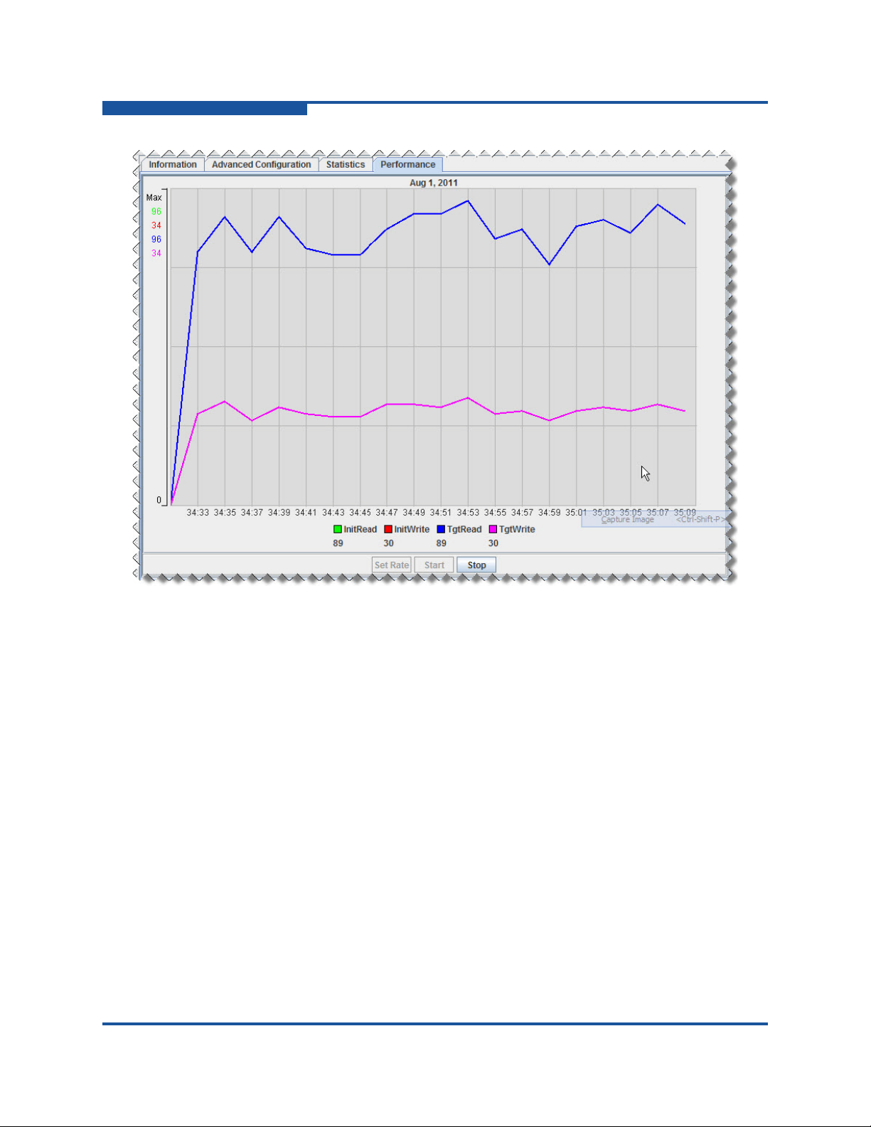
3–Viewing Router Information
FC Ports
Figure 3-10. FC Port: Performance Page
To monitor Fibre Channel port performance:
1. On the Fibre Channel port’s Statistics page, click Set Rate.
2. On the Performance Sampling Rate dialog box, type a Sampling Rate as an
integer from 1 to 30, and then click OK.
3. Click Start to begin monitoring.
The performance graph reveals port I/O performance, where:
InitRead shows the initiator’s read performance through the selected
Fibre Channel port.
InitWrite shows the initiator’s write performance through the selected
Fibre Channel port.
TgtRead shows the target’s read performance through the selected
Fibre Channel port.
TgtWrite shows the target’s write performance through the selected
Fibre Channel port.
4. To end the performance graphing session, click Stop.
3-16 ISR645610-00 B
Page 63

iSCSI Ports
When you select an iSCSI port in the router tree, the following tabbed pages
appear in the right pane:
“Information” on page 3-17
“Advanced Configuration” on page 3-20
“Statistics” on page 3-22
Information
The Information page for the selected iSCSI port contains three areas: iSCSI Port
Information, iSCSI Port Network Settings, and iSNS, as shown in Figure 3-11. If
you change any iSCSI port settings on this page, click Save to preserve your
changes.
3–Viewing Router Information
iSCSI Ports
Figure 3-11. iSCSI Port: Information Page
ISR645610-00 B 3-17
Page 64

3–Viewing Router Information
iSCSI Ports
iSCSI Port Information
The iSCSI Port Information area provides the following information and settings:
Base Name shows the full name assigned to the selected iSCSI port.
Link Status identifies the port connection status: Link Up or Link Down.
MAC Address assigned to the port; this parameter is not editable.
Actual Port Speed indicates the real speed, for example, 1Gbps/FDX. If the
port's configuration or connection has changed, the value may not be
current. Click the Refresh button to view the current speed.
Programmed Port Speed indicates the configured data rate for the port. To
change the data rate, select one of the following data rates:
Auto is the data rate determined by network attachment.
100 Mbps specifies 100 megabits per second.
1 Gbps specifies 1 gigabit per second.
Link Rate Mode is available if you selected a specific Programmed Port
Speed (not Auto). Select either Auto or Full Duplex mode.
Flow Control. If you selected a specific Programmed Port Speed (not
Auto), you can enable or disable flow control.
iSCSI Port Network Settings
The iSCSI Port Network Settings include the following:
Port Status allows you to enable or disable the port when the port link is up.
IPv4 Address. When using an IPv4 scheme, define the following
parameters:
IP is the IP to which the port responds. An uninitialized port has an IP
of all zeros.
Subnet Mask is the subnet mask used by the port.
Gateway is the gateway for the selected port.
VLAN indicates the virtual LAN configuration: Disabled or Enabled.
Enable VLAN to configure the following:
VLAN ID specifies an identification value in the range 1 to 4094.
Priority defines the priority (0 to 7) assigned to this VLAN.
IPv6 Address. When using an IPv6 scheme, define the following:
IPv6 Address 1 is the first user-assigned IPv6 to which the port
responds. A value of :: indicates that an IPv6 has not been assigned.
IPv6 Address 2 is the second user-assigned IPv6 to which the port
responds. A value of :: indicates that an IPv6 has not been assigned.
3-18 ISR645610-00 B
Page 65

3–Viewing Router Information
iSCSI Ports
IPv6 Default Router identifies the default router for the IPv6.
Depending on your network configuration, SANsurfer Router Manager
can also dynamically set the IPv6 default router.
IPv6 Link Local specifies the IPv6 link local of the port. It is not
editable.
VLAN IPv6 indicates the VLAN IPv6 configuration as Disabled or
Enabled. When enabled, you can configure the following:
VLAN ID IPv6 contains an identification value in the range 0 to
4094.
Priority IPv6 defines the priority assigned to this VLAN IPv6. To
set the priority, select a value from 0 to 7.
NOTE:
IPv6 support is available only with hardware version 6 and later and
software version 2.4.0.0 and later.
iSNS
The iSNS area of the iSCSI port Information page includes the following:
Select the Enable iSNS check box to enable (or clear the check box to
disable) iSNS support. If iSNS is disabled, complete the following:
Select either the IPv4 Server or IPv6 Server as the IP version
assigned to the IP server.
In the Server IP Address box, type the IP assigned to the iSNS server
with which this port will communicate.
ISR645610-00 B 3-19
Page 66

3–Viewing Router Information
iSCSI Ports
Advanced Configuration
Use the Advanced Configuration page to configure the router’s iSCSI port
parameters, security settings, and CHAP settings, as shown in Figure 3-12.
Figure 3-12. iSCSI Port: Advanced Configuration Page
The iSCSI port’s Advanced Configuration page provides the following parameters.
If you make any changes on this page, you must click Save (at the bottom of the
page) for the change to take effect.
iSCSI Port Number identifies the iSCSI port number (1 or 2).
IPv4 Settings include the following:
Select the Enable TCP Window Scaling check box to enable this
option. If enabled, select the Scale Factor (valid values are 0–5).
3-20 ISR645610-00 B
Page 67

3–Viewing Router Information
iSCSI Ports
Target TCP Port Number identifies the TCP port number the router
uses to receive iSCSI target commands. The iSCSI community uses
TCP port number 3260 by default. If you change this TCP port number,
you must also change all corresponding iSCSI initiators connecting to
this iSCSI target port.
IPv6 Settings include the following:
Select the Enable IPv6 Window Scaling check box to use this setting.
If enabled, select the Scale Factor (valid values are 0–5).
IPv6 Target TCP Port Number identifies the TCP port number the
router uses to receive iSCSI target commands. The iSCSI community
uses TCP port number 3260 by default. If you change this TCP port
number, you must also change all corresponding iSCSI initiators
connecting to this iSCSI target port.
Select a TCP Max Window Size of either 8192, 16384, or 32768.
Select one of the following Jumbo Frame options to indicate the MTU for
router frames:
Jumbo sets the port to support a 9000-byte MTU.
Normal sets the port to support 1500-byte MTU.
Other enables the text entry box so that you can specify a different
MTU value.
NOTE:
You should specify an MTU size greater than 1500 only when the
router is connected to a 1000Mbps Ethernet network.
Max Burst Length specifies the iSCSI maximum burst length, which ranges
from 512 to 262144 bytes, depending on iSCSI port configuration.
Max First Burst Length specifies the iSCSI maximum first burst length,
which ranges from 512 to 262144 bytes, depending on the iSCSI port
configuration.
Security Settings include the following:
Enable Header Digest enables or disables support for iSCSI header
digest. Header digest is an ISCSI feature that adds a validity check
field to iSCSI protocol data unit (PDU) headers to verify that no
corruption has occurred during transmission of the PDU header. The
iSR6152 router supports header digest in its hardware to maximize
performance.
Select the check box to enable this option; clear the check box to
disable it.
ISR645610-00 B 3-21
Page 68

3–Viewing Router Information
iSCSI Ports
Enable Data Digest enables or disables support for iSCSI data digest.
NOTE:
CHAP Settings include the following:
Enable CHAP enables or disables CHAP support. Select the check
CHAP Secret lets you define the CHAP secret used for authenticating
Data digest is an ISCSI feature that adds a validity check to iSCSI data
to verify that no corruption has occurred during transmission of the
data. The iSR6152 router supports data digest in its hardware to
maximize performance.
Select the check box to enable this option; clear the check box to
disable it.
Enabling either the Header Digest or Data Digest slows performance,
especially on 10Gb iSCSI ports.
box to enable this option; clear the check box to disable it.
an iSCSI client. The box is available only when the Enable CHAP
check box is selected. The CHAP secret can contain any ASCII
characters, and should be at least 16 characters in length.
Statistics
The Statistics page for the selected iSCSI port contains a scrollable table of
parameters and values, as shown in Figure 3-13. The table is divided into two
sections: the upper section contains statistics that are port specific, and the lower
section contains shared statistics (common to all iSCSI ports).
3-22 ISR645610-00 B
Page 69

3–Viewing Router Information
VP Groups
To view the most current statistics for this port, click Refresh at the top of the
page. To reset all values to zero, click Clear.
VP Groups
Expand the VP Groups branch in the router tree, and then select a VPGROUP
node to view virtual port group details in the right pane, as shown in Figure 3-14.
Figure 3-13. iSCSI Port: Statistics Page
Figure 3-14. VP Groups: VPGROUP_x Page
ISR645610-00 B 3-23
Page 70

3–Viewing Router Information
Discovered FC Initiators
The VP Group Information section includes the following details:
Index is the VPG index within the router.
VP Group Name identifies the name of the selected VP Group. (To change
the name, enable the VP Group, type a new name, and then click Save.
Refresh the page to see the new name. For details, see “Renaming a Virtual
Port Group” in the help system.)
Status lets you set the VPG status: Enabled or Disabled. (For details, see
“Enabling or Disabling a Virtual Port Group” in the help system.)
WWPN x specifies the world wide port name for each Fibre Channel port.
Discovered FC Initiators
Selecting the Discovered FC Initiators branch on the router tree does not provide
any information in the right pane. Select a specific discovered Fibre Channel
initiator node in the router tree to view the following pages in the right pane:
“Information” on page 3-24
“LUN List” on page 3-25
Information
The Information page for a discovered Fibre Channel initiator contains the
information shown in Figure 3-15.
Figure 3-15. Discovered FC Initiators: Information Page
The Information page contains the following elements:
Node Name identifies the initiator’s WWNN.
Port Name identifies the initiator’s WWPN.
Port ID identifies the Fibre Channel switch-assigned port identifier.
3-24 ISR645610-00 B
Page 71

LUN List
3–Viewing Router Information
Discovered iSCSI Initiators
OS Type Selection provides options to select the operating system type for
the discovered initiator. The iSR6152 router uses the OS type to enable
OS-specific commands. Type options include: Other, MS Windows, Linux,
HPUX, Mac, Solaris, VMware, OpenVMS, and Windows 2008.
Status is the activity status for the selected initiator, either Logged In
(online) or Logged Out (offline).
If you change the OS Type Selection value, click Save to preserve this setting.
The LUN list for the selected Fibre Channel discovered initiator includes details for
each LUN, as shown in Figure 3-16.
Figure 3-16. Discovered FC Initiators: LUN List Page
The LUN List page includes the following information:
Device Info indicates the name of the array information from which the LUN
is masked to this initiator.
Name identifies the array from which the LUN is masked to this initiator.
VPG_Name identifies the VPGroup name from which the LUN is mapped to
the initiator.
LUN shows the LUN ID at which it is mapped to the router from the array.
WWULN identifies the LUN’s WWULN.
Mapped ID identifies the LUN ID at which the LUN is mapped to the initiator
from the router.
Discovered iSCSI Initiators
Selecting the Discovered iSCSI Initiators branch on the router tree does not
provide any information in the right pane. Select a discovered iSCSI initiator in the
router tree to view the following pages in the right pane:
“Information” on page 3-26
“LUN List” on page 3-27
ISR645610-00 B 3-25
Page 72

3–Viewing Router Information
Discovered iSCSI Initiators
Information
The Information page for a discovered iSCSI initiator contains two sections:
Initiator Information and CHAP Settings, as shown in Figure 3-17.
Figure 3-17. Discovered iSCSI Initiators: Information Page
The Initiator Information section provides the following:
iSCSI Alias specifies the iSCSI initiator’s alias, which the initiator provides
when it logs into the iSR6152 router.
iSCSI IP shows the IP of the discovered iSCSI initiator.
iSCSI IPv6 IP shows the IPv6 IP address of the discovered iSCSI initiator.
(This information is displayed only if the initiator is logged in using an IPv6
address.)
OS Type Selection provides options to select the operating system type for
the discovered initiator. The iSR6152 router uses the OS type to enable
OS-specific commands. Type options include: Other, MS Windows, Linux,
HPUX, Mac, Solaris, VMware, and OpenVMS.
Status indicates the activity status for the selected initiator.
The CHAP Settings section provides the following:
Enable CHAP enables or disables CHAP support. Select the check box to
enable this option; clear the check box to disable it.
CHAP Secret lets you define the CHAP secret used for authenticating an
iSCSI client. The box is available only when the Enable CHAP check box is
selected.
3-26 ISR645610-00 B
Page 73

LUN List
3–Viewing Router Information
FC Discovered Targets
NOTE:
To apply any setting changes, click Save.
The LUN List page lists LUNs mapped to the iSCSI initiator, as shown in
Figure 3-18.
Figure 3-18. Discovered iSCSI Initiator: LUN List Page
The LUN List page provides the following parameters:
Device Info is the information provided by the target LUN as a result of
issuing a SCSI INQUIRY command.
Name is the target name. For Fibre Channel targets, the name is the
WWPN.
VPG Name is the name of the virtual port group (VPG).
LUN is the logical unit number.
WWULN is the world wide unique LUN name (WWULN), also provided on
page 83 of an INQUIRY command.
FC Discovered Targets
Selecting the FC Discovered Targets branch in the router tree shows two pages in
the right pane:
“FC Presented Targets” on page 3-28
“iSCSI Presented Target List” on page 3-28
Expand the FC Discovered Targets branch, and then select a specific target node
to view the following additional pages in the right pane for that target:
“Information” on page 3-29
“iSCSI Presented Target” on page 3-30
ISR645610-00 B 3-27
Page 74

3–Viewing Router Information
FC Discovered Targets
Expand the VPG branch under the target node, and then select a specific LUN to
view the following additional page in the right pane for that VPG:
“Discovered LUN Information” on page 3-31
FC Presented Targets
The FC Presented Targets page shows information for each Fibre Channel
presented target, as shown in Figure 3-19.
Figure 3-19. FC Discovered Targets: FC Presented Targets Page
The FC Presented Targets page lists the following data for each Fibre Channel
presented target:
Target WWPN/iSCSI Name
Discovered Port
VPG
Presented Port
Presented Port ID
Presented Target WWPN
To send the list of presented targets to a printer, click Print. To save the list to
a .CSV file, click Export.
iSCSI Presented Target List
The iSCSI Presented Target List page (when viewed from the FC Discovered
Targets node) shows information for each iSCSI presented target, as shown in
Figure 3-20.
3-28 ISR645610-00 B
Page 75

3–Viewing Router Information
FC Discovered Targets
Figure 3-20. FC Discovered Targets: iSCSI Presented Target List Page
The iSCSI Presented Target List page shows the following data for each iSCSI
presented target:
Target WWPN
IP Address
Alias
iSCSI Name
To send the list of presented targets to a printer, click Print. To save the list to
a .CSV file, click Export.
Information
The Information page for a Fibre Channel discovered target contains non-editable
product data, as shown in Figure 3-21.
Figure 3-21. FC Discovered Targets: Information Page
ISR645610-00 B 3-29
Page 76

3–Viewing Router Information
FC Discovered Targets
The Information page contains the following FC target information:
Product Vendor is the product vendor as reported by the SCSI INQUIRY
command.
Product ID is the product ID as reported by the SCSI INQUIRY command.
Product Revision is the product revision as reported by the SCSI INQUIRY
command.
Target Path specifies either the router port on which the target is
discovered, or Offline.
iSCSI Presented Target
The iSCSI Presented Target page provides detailed Fibre Channel target
information and a list of the iSCSI presentations of the target, as shown in
Figure 3-22.
Figure 3-22. FC Discovered Targets: iSCSI Presented Target Page
The iSCSI Presented Target page contains the following information:
Device Product Vendor is the vendor name of the target device as reported
by the SCSI INQUIRY command.
Device Product ID is the product ID name of the target device as reported
by the SCSI INQUIRY command.
Device Product Rev is the product revision of the target device as reported
by the SCSI INQUIRY command.
Device Node Name is the WWNN of the target device.
Device Port Name is the WWPN of the target device.
Device Port ID is the target device’s port ID.
Target WWPN is the world wide port name of the target.
IP is the IP on which the target is presented.
3-30 ISR645610-00 B
Page 77

Alias is the iSCSI alias of the presented target.
iSCSI Name is the presented target’s iSCSI name.
Discovered LUN Information
For an FC Discovered Target, select a target, expand the VPGs below that target,
and then select a LUN to view the Discovered LUN Information page in the right
pane. This page provides details on the selected Fibre Channel target LUN.
Figure 3-23 shows the Discovered LUN Information page.
3–Viewing Router Information
FC Discovered Targets
Figure 3-23. FC Discovered Targets: Discovered LUN Information Page
The Discovered LUN Information page contains the following information:
Product Vendor is the vendor name of the LUN as reported by the SCSI
INQUIRY command.
Product ID is the product ID of the LUN as reported by the SCSI INQUIRY
command.
Product Revision is the product revision of the LUN as reported by the
SCSI INQUIRY command.
LUN is the logical unit number.
WWULN is the world wide unique name of the LUN as reported on
page 0x83 of the SCSI INQUIRY command. It also identifies the extended
unique identifier (EUI) and name address authority (NAA) based WWULNs.
Serial Number is the LUN serial number.
ISR645610-00 B 3-31
Page 78

3–Viewing Router Information
iSCSI Discovered Targets
Size indicates the LUN size in GB.
Status is the current state of the LUN, either Online or Offline.
iSCSI Discovered Targets
The iSCSI Discovered Targets branch on the router tree does not provide any
information in the right pane. Select a discovered target to view the Information
page for that target, as shown in Figure 3-24.
Figure 3-24. iSCSI Discovered Targets: Information Page
Information
The Information page contains two sections: General Information and CHAP
Settings.
General Information includes the following:
Product Vendor shows the product vendor as reported by the SCSI
INQUIRY command.
Product ID shows the product ID as reported by the SCSI INQUIRY
command.
3-32 ISR645610-00 B
Page 79

3–Viewing Router Information
iSCSI Discovered Targets
Product Revision shows the product revision as reported by the SCSI
INQUIRY command.
IP shows the IP of the presented iSCSI target.
iSCSI Name shows the presented iSCSI target’s name.
Target Path shows the router’s iSCSI port where the target was
discovered.
CHAP Settings provides an option you can use to set the CHAP option as
follows:
Enable CHAP check box allows you to enable CHAP when connecting
to this target.
CHAP Secret is the string used for the CHAP secret when connecting
to this target. The box is available only when the Enable CHAP check
box is selected.
NOTE:
If you change the CHAP Settings, you must click Save for the change
to take effect.
ISR645610-00 B 3-33
Page 80

3–Viewing Router Information
Arrays
Arrays
Expand the Arrays branch in the left pane, and then select a specific storage array
node to view the Information page for that array in the right pane. Figure 3-25
shows an example.
Figure 3-25. Arrays: Information Page
The Information page for a storage array contains the following general
information, some of which is editable:
Symbolic Name is the user-defined array name.
Product Vendor is the product vendor as reported by the SCSI INQUIRY
command.
Product ID is the product ID of the LUN as reported by the SCSI INQUIRY
command.
Product Revision is the product revision of the LUN as reported by the
SCSI INQUIRY command.
3-34 ISR645610-00 B
Page 81

3–Viewing Router Information
iSCSI Presented Targets
Target Type for the array can be specified as either Source, Destination,
Src+Dest (both source and destination type), or None.
Array Bandwidth can be specified as one of the following: Slow
(50BMB/s), Medium (200BMB/s), Fast (1600MB/s), User Defined, or Max
Available.
User-defined Bandwidth (MB/s) becomes available if the selected Array
Bandwidth setting is User Defined. Type an integer in the box.
Load Balancing is either Enabled or Disabled for this array.
LUN Info Display determines whether the array’s LUNs are identified by
LUN ID, WWULN, or Serial Number.
Array License shows whether a data migration array license has been
applied to the array.
Physical Target Ports information includes:
Port specifies the target port number.
WWPN specifies the target port WWPN.
Port ID indicates the ID assigned by the Fibre Channel fabric or
AL_PA when connected on a private loop.
NOTE:
To apply changes made to this page, click Save.
iSCSI Presented Targets
Selecting the iSCSI Presented Targets branch on the router tree does not provide
any information in the right pane. Expand the iSCSI Presented Targets branch,
and then select a specific presented target to view the Information page for that
target in the right pane.
Information
The Information page for an iSCSI presented target contains the information and
options shown in Figure 3-26.
ISR645610-00 B 3-35
Page 82

3–Viewing Router Information
iSCSI Presented Targets
Figure 3-26. iSCSI Presented Targets: Information Page
Information for the selected iSCSI presented target includes:
iSCSI Name is the presented iSCSI target’s name.
iSCSI Alias is the presented iSCSI target’s alias. You can change the alias
by typing a valid name in the box.
Product Vendor is the product vendor as reported by the SCSI INQUIRY
command.
Product ID is the product ID as reported by the SCSI INQUIRY command.
Product Revision is the product revision as reported by the SCSI INQUIRY
command.
VPGroup specifies the virtual port group on which the Fibre Channel target
is located.
IP Address is the address of the presented iSCSI target.
CHAP Settings options include the following:
Enable CHAP enables or disables CHAP support. Select the check
box to enable this option; clear the check box to disable it.
CHAP Secret lets you define the CHAP secret used for authenticating
an iSCSI client. The box is available only when the Enable CHAP
check box is selected.
3-36 ISR645610-00 B
Page 83

NOTE:
To apply changes made to this window, click Save.
FCIP Routes
Expand the FCIP Routes branch in the left pane, and then select a specific FCIP
Route Info node to view the following pages for that route in the right pane:
“FCIP Route Info” on page 3-38
“Statistics” on page 3-42
3–Viewing Router Information
FCIP Routes
ISR645610-00 B 3-37
Page 84

3–Viewing Router Information
FCIP Routes
FCIP Route Info
The FCIP Route Info page contains the information that defines the selected FCIP
route, as shown in Figure 3-27.
Figure 3-27. FCIP Routes: FCIP Route Info Page
3-38 ISR645610-00 B
Page 85

3–Viewing Router Information
FCIP Routes
The FCIP Route Info page contains the following information and configurable
parameters for the currently selected FCIP route. If you make any changes to the
FCIP route configuration, click the Save button at the bottom of the page.
FCIP Interfaces Status allows you to enable or disable the FCIP route.
Disabling the route places the Fibre Channel and GbE ports in a down state,
but still retains all route configuration parameters.
FC Port identifies the Fibre Channel port number assigned to the FCIP route
when it was created.
FC Link Status indicates the link state (Up or Down) of the FCIP route:
Up indicates the FCIP route is available for use. An FC Link Status of
Up requires a TCP connection between the two routers, and that the
corresponding Fibre Channel ports of the routers are up (link
established).
Down indicates the FCIP route is not available for use.
GigE Port identifies the gigabit Ethernet (GbE) port number assigned to the
FCIP route when it was created.
GigE Link Status indicates the link state (up or down) of the GbE port
assigned to the FCIP route.
Up indicates the GbE port is available for use (link established).
Down indicates the GbE port is not available for use (cable
disconnected, negotiation failure, and so on).
Local IP Address allows you to define the IP to be used by the GbE port of
the local router. The local router for FCIP traffic generates IP datagrams with
the Source IP Address set to the value of the Local IP Address. An
uninitialized port shows an IP of all zeros.
Remote IP Address allows you to define the IP of the GbE port on the
remote router. The local router for FCIP traffic generates IP datagrams with
the Destination IP Address set to the value of the Remote IP Address.
Subnet Mask allows you to define the subnet mask used by the GbE port
for the local and remote IP addresses.
Gateway IP indicates the IP address of the entrance to another network. If
the IP addresses of the FCIP routers are not in the same network, the
gateway IP address specifies where the routers send their traffic to be
forwarded by the gateway.
ISR645610-00 B 3-39
Page 86

3–Viewing Router Information
FCIP Routes
Jumbo Frames indicates that the use of jumbo Ethernet frames is enabled.
Jumbo frames are Ethernet frames with payloads greater than 1500 bytes,
with a maximum size of 9000 bytes. Using jumbo frames requires all the
network equipment in the route to be configured for jumbo frames. Jumbo
frames can increase bandwidth in some networks because the number of
headers to be processed is decreased when each frame contains more user
data. However, some networks may defer or discard jumbo frames when
their buffer resources run low.
Select one of the following options for jumbo frames:
Jumbo improves data transfer performance, but requires all switches,
Normal is a common setting that works in typical configurations. If you
routers, and devices to support and be configured for jumbo frames. If
any of the equipment is not configured for jumbo frames, that device
truncates frames that exceed its MTU size (typically 1,500 bytes).
cannot configure all the network equipment in a route for jumbo
frames, select Normal (maximum of 1,500 bytes per frame).
Other enables the setting of the frame payload size to a specific value.
This option is typically required when IP traffic is encrypted, because
the encryption adds overhead to each frame and reduces the size of
the available frame payload (usually less than 1,500 bytes). If the
network has some equipment with an MTU size less than 1,500, select
Other and set the size to the smallest MTU of the network equipment
comprising the route.
NOTE:
Use jumbo frames only with 1000Mbps Ethernet networks.
TCP Window Size indicates the maximum size (in bytes) of the TCP
window, which is the number of unacknowledged bytes. TCP transmits data
to the remote peer until the window is full (number of unacknowledged bytes
equals TCP window size). After the window is full, new data transmission is
halted until acknowledgements for sent data are received from the remote
peer.
Window Scaling indicates whether TCP window scaling is enabled or
disabled. TCP window scaling applies a multiplier to the TCP Window Size
to extend the TCP window size beyond the maximum value originally
defined for TCP.
Window Scaling Factor is the multiplier (0–9) to be applied to the TCP
Window Size when Window Scaling is enabled, as shown in Tab le 3- 1.
3-40 ISR645610-00 B
Page 87

Table 3-1. TCP Window Scaling Factor
3–Viewing Router Information
FCIP Routes
TCP Window Size
(in bytes)
32767 0
32767 1 64,534
32767 2 131,068
32767 3 262,136
32767 4 524,272
32767 5 1,048,544
32767 6 2,097,088
32767 7 4,194,176
32767 8 8,388,352
32767 9 16,776,704
Scale Factor
(scaling disabled)
Actual Window
Size (in bytes)
32,767
TCP Port Number identifies the TCP port number on which the FCIP server
listens for TCP connections; the default value for FCIP is 3225.
Programmed GigE Port Speed indicates the value specified for the GbE
port speed by the user when the FCIP route was created or modified. Select
one of the following values:
Auto allows the router to negotiate the link speed with the peer port.
The router advertises speeds of 1Gbps and 100Mbps.
100 Mbps forces the port link speed to 100Mbps.
1 Gbps forces the link speed to 1Gbps. With this option, the router
negotiates with the peer port, but only advertises a speed of 1Gbps.
GigE Port Speed indicates the actual value of the GbE port speed.
Typically, this value is the same as the Programmed GigE Port Speed.
However, when the Programmed GigE Port Speed is Auto, this field
indicates the negotiated port speed.
GigE Port Flow Control indicates whether flow control (IEEE802.3x Pause)
is enabled or disabled. When Enabled (the default), the corresponding GbE
port sends and receives Ethernet pause frames. When pause frames are
received, the port suspends sending Ethernet traffic. When the port runs low
on receive buffers, it sends a pause frame.
ISR645610-00 B 3-41
Page 88

3–Viewing Router Information
FCIP Routes
VLAN Enabled indicates whether the use of virtual LANs is enabled or
disabled. The default is Disabled.
VLAN ID specifies the VLAN ID assigned to the FCIP route when VLAN use
is enabled. The VLAN ID segregates traffic in a LAN, and must be the same
on both routers participating in the FCIP route (local and remote routers
must be using same VLAN ID) and on the Ethernet switches.
VLAN Priority specifies the priority of the VLAN assigned to the FCIP route
when VLAN use is enabled. In a network with multiple VLANs, the VLAN
Priority box prioritizes Ethernet traffic by giving higher preference to traffic
in the network over non-VLAN traffic and traffic from VLANs with lower
priorities. Level 1 is the lowest priority, level 7 is the highest priority, and level
0 specifies no VLAN.
Error Detect Timeout sets the error detect timeout value by selecting one
of five options: 1 to 5 seconds. The default is one second.
Resource Allocate Timeout sets the resource allocate timeout value to one
of five options: 1 to 5 seconds. The default is one second.
Statistics
FCIP Timestamp enables or disables FCIP timestamps. The default is
Enabled.
FCIP SW Compression indicates whether software compression is
enabled, disabled, or automatic (the default is Disabled). Depending on the
data, software compression may result in lower bandwidth operations. If the
data are highly compressible, the compressed FCIP PDU is significantly
smaller than the original Fibre Channel frame.
Bandwidth (Mbit/sec) defines the maximum bandwidth (in megabits per
second) the GbE port will use during transmits. Supported values range from
1 to 1000 Mbps. Use this setting to limit the bandwidth used by the FCIP
route so it does not consume all the available link bandwidth. For example, if
the slowest link in the WAN is a DS-3 link, the maximum available bandwidth
is 45 megabits per second. To limit the FCIP route to 33 percent of the
overall link bandwidth, set the bandwidth to 15 megabits per second.
The Statistics page for FCIP routes lists parameters and values, as shown in
Figure 3-28. To update the statistics, click Refresh. To reset all values to zero,
click Clear.
3-42 ISR645610-00 B
Page 89

3–Viewing Router Information
FCIP Routes
Figure 3-28. FCIP Routes: Statistics Page
ISR645610-00 B 3-43
Page 90

3–Viewing Router Information
FCIP Routes
3-44 ISR645610-00 B
Page 91

4 Viewing Service
Information
SANsurfer Router Manager lets you monitor and manage licensed features such
as data migration by selecting components on the Services page in the tree in the
left pane (for details, see “Services Tree” on page 2-13). Information,
configuration, and data for the selected component appears in the right pane.
The following sections describe these components:
“Router iSR6152” on page 4-1
“Data Migration Jobs” on page 4-3
Router iSR6152
The top of the SANsurfer Router Manager services tree in the left pane identifies
the connected iSR6152 by serial number. Click the router in the left pane to view
the following tabbed page in the right pane:
“Data Migration Info” on page 4-2
ISR645610-00 B 4-1
Page 92

4–Viewing Service Information
Router iSR6152
Data Migration Info
The Data Migration Info page for the router services contains data migration
license usage data, as shown in Figure 4-1.
Figure 4-1. Data Migration Info Page
The Data Migration Info page contains the following information:
The Data Migration Usage Information section provides the amounts of
capacity licensed, consumed, scheduled or in-process, and available.
The Array Based Licenses Information section provides quantities of
migration array-based licenses issued, used, and available.
Select the Data Migration Report check box to specify settings for
uploading, saving, or clearing information in the data migration report. In the
URL box, type the URL where you want to save or upload the report. Then
click the buttons to specify the following options:
Click Set URL to save the event notification address (specified in the
URL box) that indicates where you want to upload the report. If you do
not click Set URL, the URL is not saved.
Click Upload Report to send the report to the Web page indicated in
the URL box.
Click Save Report to create a report and save it in the router's ftp
folder.
Click Clear Report to delete all reports from the router’s ftp folder.
4-2 ISR645610-00 B
Page 93

Data Migration Jobs
When you click a data migration job in the services tree, information for that job
appears in the right pane. Details for data migration jobs are shown on the
following pages:
“Active Data Migration Jobs” on page 4-3
“Synchronizing Jobs” on page 4-4
“Completed Data Migration Jobs” on page 4-4
Active Data Migration Jobs
The Active Data Migration Jobs page provides data for the currently running data
migration jobs, as shown in Figure 4-2.
4–Viewing Service Information
Data Migration Jobs
Figure 4-2. Data Migration Jobs: Active Data Migration Jobs Page
The Active Data Migration Jobs page contains the following information:
Group Name shows the migration group name for which the migration,
compare, or scrubbing job is scheduled.
Job ID identifies by number the scheduled migration, compare, or scrubbing
job.
Job Name identifies by name the scheduled migration, compare, or
scrubbing job.
Type shows the job type, either Offline, Migration, Compare, or
Scrubbing.
Status shows the job state, either Running, Paused, Stopped, or Failed.
% Completed shows the percent of the job that is finished.
Start Time indicates the date and time that the job began.
End Time indicates the date and time that the job finished.
Source Array - LUN indicates the name of the source array and LUN from
which data is currently being migrated to the destination LUN.
Dest Array - LUN indicates the name of the destination array and LUN to
which data is currently being migrated from the source LUN.
ISR645610-00 B 4-3
Page 94

4–Viewing Service Information
Data Migration Jobs
Synchronizing Jobs
The data migration job synchronization feature is available only for online data
migration. SANsurfer Router Manager for the iSR6152 currently supports only
offline data migration. Therefore the Synchronizing Jobs page will not contain any
information, as shown in Figure 4-3.
Figure 4-3. Data Migration Jobs: Synchronizing Jobs Page
Completed Data Migration Jobs
The Completed Data Migration Jobs page provides data for finished data
migration jobs, as shown in Figure 4-4.
Figure 4-4. Data Migration Jobs: Completed Data Migration Jobs Page
The Completed Data Migration Jobs page contains the following information:
Group Name shows the migration group name for which the migration,
compare, or scrubbing job was scheduled.
Job ID identifies by number the completed migration, compare, or scrubbing
job.
Job Name identifies by name the completed migration, compare, or
scrubbing job.
Type shows the job type, either Offline, Migration, Compare, or
Scrubbing.
Status shows the job state, Completed.
% Completed shows the job as 100% percent finished.
Start Time indicates the date and time that the job began.
End Time indicates the date and time that the job finished.
4-4 ISR645610-00 B
Page 95

4–Viewing Service Information
Data Migration Jobs
Source Array - LUN indicates the name of the source array and LUN from
which data was migrated to the destination LUN.
Dest Array - LUN indicates the name of the destination array and LUN to
which data was migrated from the source LUN.
ISR645610-00 B 4-5
Page 96

4–Viewing Service Information
Data Migration Jobs
4-6 ISR645610-00 B
Page 97

A Simple Network
Management Protocol
(SNMP)
Introduction
Simple network management protocol (SNMP) provides monitoring and trap
functions for managing the router through third-party applications that support
SNMP. The router firmware supports SNMP versions 1 and 2 and a QLogic
management information base (MIB) (see page A-2). You may format the traps
using SNMP version 1 or 2 (see page A-11).
SNMP Properties
You can set the SNMP properties using SANsurfer Router Manager (see “SNMP
Management” on page 3-10). Table A-1 describes the SNMP properties.
Table A-1. SNMP Properties
Parameter Description
Read community A password that authorizes an SNMP management server to
read information from the router. This is a write-only field. The
value on the router and the SNMP management server must
be the same. The read community password can be up to
32 characters excluding the number sign (#), semicolon (;), and
comma (,). The default is password is public.
Trap community A password that authorizes an SNMP management server to
receive traps. This is a write-only field. The value on the router
and the SNMP management server must be the same. The
trap community password can be up to 32 characters excluding
the number sign (#), semicolon (;), and comma (,). The default
password is public.
System location Specifies the name of the router location. The name can be up
to 64 characters excluding the number sign (#), semicolon (;),
and comma (,). The default is undefined.
ISR645610-00 B A-1
Page 98

A–Simple Network Management Protocol (SNMP)
Management Information Base (MIB)
Table A-1. SNMP Properties (Continued)
Parameter Description
System contact Specifies the name of the person to be contacted to respond to
trap events. The name can be up to 64 characters excluding
the number sign (#), semicolon (;), and comma (,). The default
is undefined.
Authentication traps Enables or disables authentication trap generation in response
to authentication failures. The default is disabled.
SNMP Trap Configuration
SNMP trap configuration supports setting up to eight trap destinations. Choose
from Traps 1 through 8 to configure each trap. Table A-2 describes the
parameters for configuring an SNMP trap.
Table A-2. SNMP Trap Configuration Parameters
Parameter Description
Trap n enabled Enables or disables trap n. If disabled, the trap is not configured.
Trap address
Trap port
Trap version Specifies the SNMP version (1 or 2) with which to format traps.
a
Traps (other than 0.0.0.0) and trap port combinations must be unique. For example, if trap 1 and
trap 2 have the same address they must have different port values. Similarly, if trap 1 and trap 2
have the same port value, they must have different addresses.
a
a
Specifies the IP to which the SNMP traps are sent. A maximum of
eight trap addresses is supported. The default for traps is 0.0.0.0.
The port number on which the trap is sent. The default is 162.
Management Information Base (MIB)
The following sections describe the QLogic management information base (MIB).
The MIB consists of four object groups:
“System Information” on page A-3
“Network Port Table” on page A-4
“Fibre Channel Port Table” on page A-6
“Sensor Table” on page A-8
A-2 ISR645610-00 B
Page 99

System Information
The system information objects provide the system serial number, version
numbers (hardware, software, and agent), and number of ports (Fibre Channel
and GbE).
qsrSerialNumber
Syntax SnmpAdminString
Access Read only
Description The system serial number.
qsrHwVersion
Syntax SnmpAdminString
Access Read only
Description The system hardware version number.
qsrSwVersion
A–Simple Network Management Protocol (SNMP)
Management Information Base (MIB)
Syntax SnmpAdminString
Access Read only
Description The system software (firmware) version number.
qsrNoOfFcPorts
Syntax Unsigned32
Access Read only
Description The number of Fibre Channel ports on the system.
qsrNoOfGbEPorts
Syntax Unsigned32
Access Read-only
Description The number of gigabit Ethernet ports on the system.
qsrAgentVersion
Syntax SnmpAdminString
Access Read only
Description The version number of the agent software on the
system.
ISR645610-00 B A-3
Page 100

A–Simple Network Management Protocol (SNMP)
Management Information Base (MIB)
Network Port Table
The network port table contains a list of network ports that are operational on the
router. The entries in this table include the management port, the iSCSI ports, and
the TOE ports on the router. A single gigabit Ethernet port can function as an
iSCSI port and a TOE simultaneously; therefore, there may be up to two entries
for a given gigabit Ethernet port.
qsrNwPortTable
Syntax Sequence of QsrNwPortEntry
Access Not accessible
Description The entries in this table include the management port,
iSCSI port, and TOE port on the router.
qsrNwPortEntry
Syntax QsrNwPortEntry
Access Not accessible
Description Each entry (row) contains information about a specific
network port.
QsrNwPortEntry
A network port entry consists of the following sequence of objects:
qsrNwPortRole QsrPortRole
qsrNwPortIndex unsigned32
qsrNwPortAddressMode INTEGER
qsrIPAddressType InetAddressType
qsrIPAddress InetAddress
qsrNetMask InetAddress
qsrGateway InetAddress
qsrMacAddress MacAddress
qsrNwLinkStatus QsrLinkStatus
qsrNwLinkRate QsrLinkRate
A-4 ISR645610-00 B
 Loading...