

Page 1

KABELLOSES RÜCKFAHRKAMERASYSTEM
WIRELESS BACK-UP CAMERA SYSTEM
SYSTÈME DE CAMERA DE RECUL SANS FIL
BEZDRÔTOVÝ KAMEROVÝ SYSTÉM CÚVANIA
with 3,5 inch (8,9 cm) monitor
mit 3,5” (8,9 cm) Monitor
avec écran 3,5 (8,9 cm) pouces
s 3,5” (8,9 cm) monitorom
RVC3610P, Art.-Nr.: 16238
DE
Page 2

2
EINLEITUNG
Der Artikel RVC3610P gehört zur Familie der zukunftsweisenden Auto-Rückfahr-Kamera-
WICHTIGE SICHERHEITSHINWEISE
ZUBEHÖR
Systeme der Firma ProUser.
Die kabellose Rückfahr-Kamera mit Monitor ermöglicht es Ihnen bei ordnungsgemäßer
Bedienung, hinter Ihr Auto, Ihren Anhänger oder Mini-Van zu sehen. Es wurden
zahlreiche Maßnahmen bei der Qualitätskontrolle ergriffen, um Ihnen ein Top Produkt zu
Ihrer Zufriedenheit zu liefern.
Bitte lesen Sie die Bedienungsanleitung sorgfältig durch und folgen Sie den
Sicherheitshinweisen und der Montageanleitung.
Vor der Montage
Falls Sie sich nicht sicher fühlen, dieses System an die 12V Stromversorgung Ihres
Fahrzeuges selbstständig zu montieren (bohren von Löchern, abnehmen von
Verkleidungen etc.) nehmen Sie Kontakt zu Ihrem Autohaus oder zur Kfz-Werkstatt Ihres
Vertrauens auf. Dort können Sie eine professionelle Montage des Systems in Auftrag
geben.
Störung
Dieses Kamera-System kann, genau wie andere kabellosen Systeme, bestimmten
Störungen unterliegen. Störungen können verursacht werden durch Handys, Bluetooth,
Headsets, Navigationssysteme und anderen elektrischen Geräten.
Reparatur
Dieses Kamera-System darf nicht geöffnet werden! Bei jeglichem Versuch einer
Reparatur erlischt die Garantie.
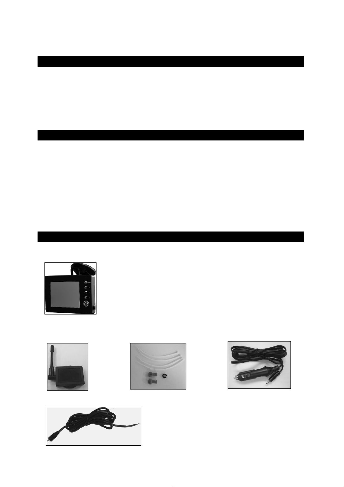
1. Monitor mit Befestigungsarm 2. Kamera mit Befestigungsplatte
3. Sender 4. Installations- Material 5. 12V Kabel für Monitor
6. Netzkabel für Sender
Page 3

3
MONTAGE
Diese Bedienungsanleitung ist nicht für alle Fahrzeuge anzuwenden. Sie ist ein
genereller Leitfaden für die meisten Fahrzeuge. Bei fahrzeugspezifischen Fragen
wenden Sie sich bitte an Ihren Fahrzeughersteller.
Montage der Kamera
Es gibt verschiedene Möglichkeiten, die Kamera an der Rückseite Ihres Fahrzeuges zu
befestigen. die Gebräuchlichste ist, die Kamera nahe dem Nummernschild zu befestigen.
Sie können die mitgelieferte Montageplatte hinter dem Nummernschild befestigen. Auf
diese Montageplatte können Sie nun die Kamera montieren.
Die Kamera ist vertikal schwenkbar, bitte stellen Sie diese nach den Gegebenheiten ein.
Bei manchen Fahrzeugen ist es leider nicht möglich, die Kamera nahe dem Nummernschild zu befestigen. Suchen Sie sich eine andere Stelle am Heck Ihres Autos und
befestigen Sie die Kamera mit den mitgelieferten Schrauben und Muttern.
1. Nehmen Sie das Nummernschild aus der Halterung und lösen Sie danach die
Schrauben des Nummernschildhalter und nehmen dieses ab.
2. Positionieren Sie die Befestigungsplatte mit der Kamera hinter dem Nummernschildhalter und befestigen Sie die Befestigungsplatte und den Nummernschildhalter
am Fahrzeug.
3. Befestigen Sie nun Ihr Nummernschild wieder auf dem Nummernschildhalter.
Page 4

4
4. Wählen Sie jetzt eine Stelle, wo Sie das Elektrokabel der Kamera durch die Karosserie
Ihres Autos zum Stromkabel des Rückfahrlichtes ziehen können.
5. Einige Autos haben in der Nähe des Kennzeichens eine Bohrung, wo Sie das Kabel
durchziehen können. Falls das nicht der Fall ist, müssen Sie in der Nähe des
Kennzeichens, dicht an der Stelle, wo sich das Kabel der Kamera befindet, selber ein
Loch bohren. Wenn Sie den Platz für das Bohrloch festgelegt haben können Sie die
Kamera und das Kennzeichen wieder demontieren. Wenn Sie eine vorhandene
Öffnung benutzen, können Sie die zwei folgenden Schritte überspringen.
6. Bevor Sie bohren, demontieren Sie die Kamera und das Nummernschild. PRÜFEN SIE,
BEVOR SIE BOHREN, WAS SICH AUF DER RÜCKSEITE DER STELLE BEFINDET, WO
SIE BOHREN WOLLEN! Sorgen Sie z.B. dafür, dass sich dort keine Elektrokabel,
Flüssigkeitstanks oder Leitungen befinden. Beachten Sie alle Vorsichtsmaßnahmen!
7. Nachdem Sie gebohrt haben, befestigen Sie den mitgelieferten Kantenschutz in der
Bohrung, um das Kabel vor den scharfen Rändern des Bohrloches zu schützen. Dann
ziehen Sie das Kabel der Kamera ins Fahrzeuginnere.
8. Befestigen Sie den Sender im Kofferraum. Verbinden Sie das Kabel der Kamera und
das Kabel des Senders mit dem Sender.
9. Schalten Sie die Zündung Ihres Auto an (nicht starten!), ziehen Sie die Handbremse
an und legen Sie den Rückwärtsgang ein. Dann schauen Sie am Heck Ihres Autos, wo
sich der Rückfahrscheinwerfer befindet. Um die Kabel vom Rückfahrscheinwerfer zu
finden, müssen Sie die Rückseite der Heckbeleuchtung öffnen und die
entsprechenden Kabel orten. Ggf. suchen Sie hierzu Ihr Autohaus oder die KfzWerkstatt Ihres Vertrauens auf.
10. Wenn Sie die entsprechenden Kabel gefunden haben, legen Sie das Kabel des
Senders an den Verbindungspunkt. Sorgen Sie bitte dafür, das die Befestigung des
Kabels sicher und fest ist, damit es beim Öffnen und Schließen der Heckklappe nicht
beschädigt werden kann. Verlegen Sie das Kabel niemals außerhalb des Autos!
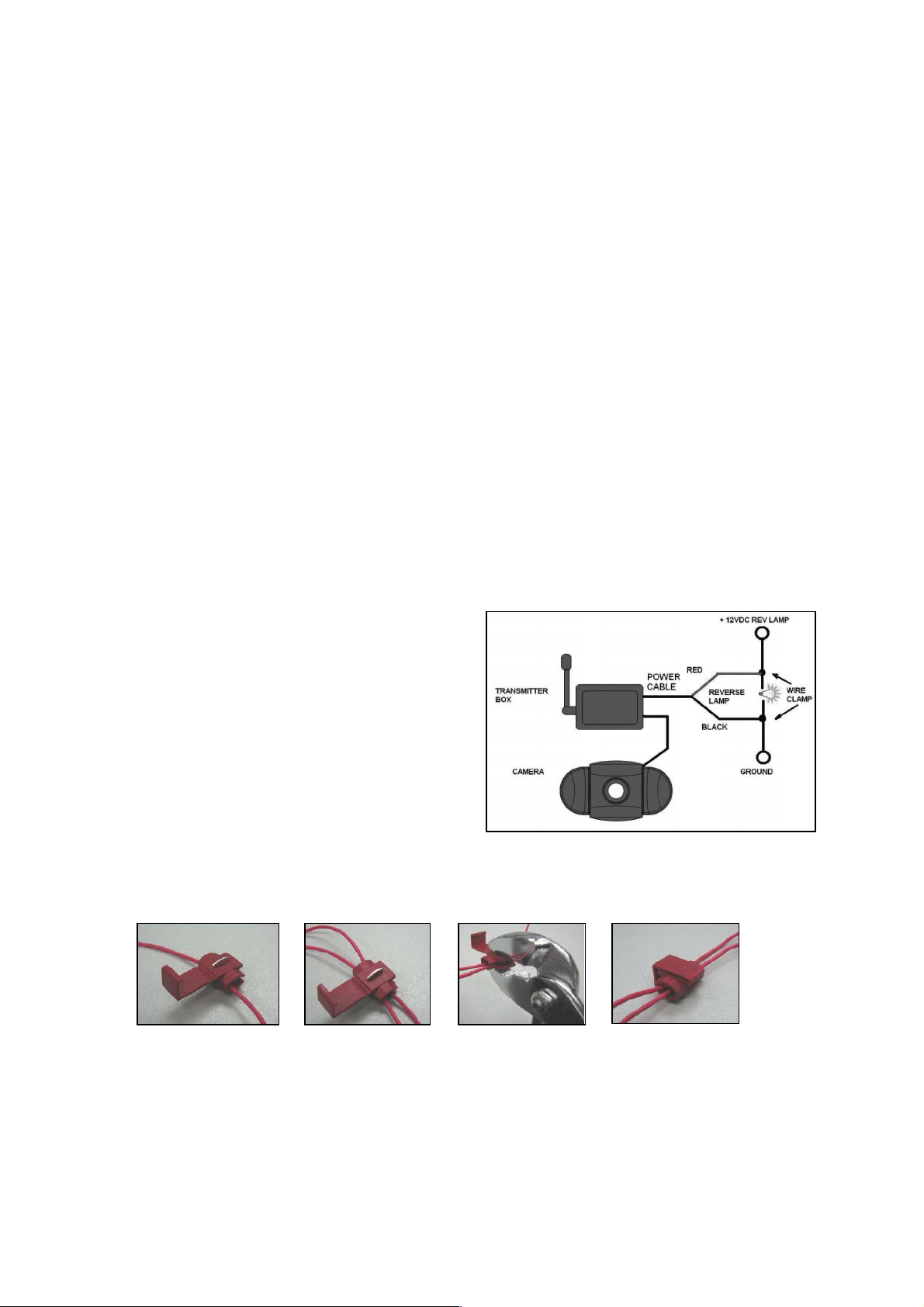
11. An der Kontaktdose des Rückfahr-
scheinwerfers sind zwei Drähte befestigt.
Meistens ist der negative Draht schwarz
und der positive farbig. Wenn Sie unsicher
sind, können Sie mit einem 12 V Multimeter
(im Fachhandel erhältlich) prüfen, welcher
Draht positiv bzw. negativ ist. Folgen Sie
der Bedienungsanleitung des Multimeters
für den sicheren Gebrauch.
12. Wenn Sie festgestellt haben, welcher Draht
positiv bzw. negativ ist, schalten Sie die
Zündung aus und entfernen Sie das
negative Kabel Ihrer Autobatterie. So ist
sichergestellt, das kein Strom auf den Drähten ist.
13. Verbinden Sie den roten Draht vom Kabel des Senders mit dem positive Draht des
Rückfahrscheinwerfers. Benutzen Sie dazu die beiliegenden Kabelklemmen. Drücken
Sie die Klemmen fest mit einer Zange zusammen und clipsen Sie die rote
Plastikabdeckung über diese Kontaktstellen.
14. Verbinden Sie nun den schwarzen Draht des Sender-Kabels mit dem negative Draht
des Rückfahrscheinwerfers. (Benutzen Sie auch hier die Kabelklemmen)
15. Verschließen Sie die Heckleuchte wieder (achten Sie darauf, dass die Glühlampe
eingesetzt ist). Benutzen Sie Kabelbinder und spezielle Tapes (für Kabelverbindungen), damit alle Drähte und Kabel sicher und fest verlegt sind!
16. Schließen Sie das negative Kabel Ihrer Autobatterie wieder an.
Page 5

5
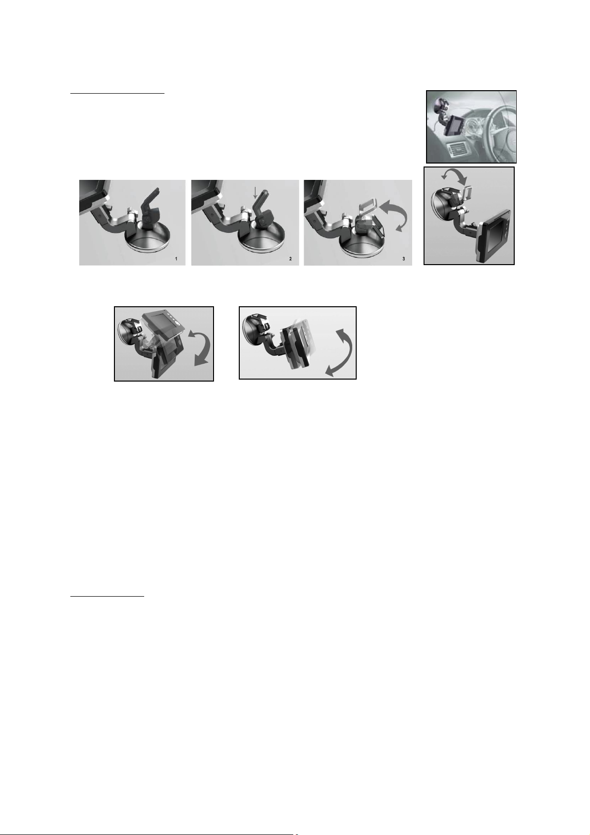
Montage des Monitors
Wenn Sie den passenden Platz zur Befestigung des Monitors
gefunden haben, vergewissern Sie sich, das Ihnen nicht die
Sicht versperrt wird während der Fahrt.
1. Reinigen Sie die Stelle gründlich vor der Befestigung
2. Positionieren Sie den Sauger auf der von Ihnen gewählten Fläche
3. Pressen Sie den Sauger fest auf die gereinigte Oberfläche und
legen Sie den Hebel um damit der Sauger sicher und fest sitzt.
4. Schieben Sie den Monitor in die am Sauger befindliche Halterung.
5. Drehen Sie den Arm der Halterung und richten Sie den Bildschirm in die gewünschte
Position aus. Drehen Sie nun die Schrauben an.
6. Legen Sie das Netzkabel zum Zigarettenanzünder. Verlegen Sie das Kabel so, das es
zu keinen Einschränkungen oder Behinderungen während der Fahrt kommen kann.
7. Stecken Sie den kleinen 12V Stecker von dem Netzkabel in die Öffnung auf der
rechten Seite vom Monitor.
8. Den anderen Stecker des Kabels stecken Sie in den Zigarettenanzünder.
Um den festen Halt des Saugers zu gewährleisten wird der Gebrauch nur unter
Einhaltung folgender Voraussetzungen empfohlen:
• Die Temperatur der Oberfläche sollte zwischen 21 und 38 Grad Celsius liegen.
• Der Gebrauch unter 10 Grad Celsius sollte vermieden werden.
• Der Gebrauch bei direkter Sonneneinstrahlung sollte vermieden werden.
Die Befestigung sollte vor direkter Sonneneinstrahlung geschützt werden.
ACHTUNG: BEI EXTREM HELLEN LICHTVERHÄLTNISSEN BENÖTIGT DER
MONITOR EINIGE SEKUNDEN UM SICH DIESEN LICHTVERHÄLTNISSEN
ANZUPASSEN. WARTEN SIE BITTE MIT DEM RÜCKWÄRTS FAHREN BIS SICH DAS
BILD STABILISIERT HAT.
System Test
1. Prüfen Sie, ob Sie das negative Kabel der Autobatterie wieder befestigt haben.
2. Schalten Sie die Zündung Ihres Autos an (bitte nicht starten)
3. Ziehen Sie die Handbremse an und legen Sie den Rückwärtsgang ein.
4. Schauen Sie auf den Monitor. Wenn dieses Bild nicht identisch ist mit dem Bild, was
Sie im Rückspiegel sehen, drücken Sie den Bild-Orientierungs (Image Orientation)
Knopf am Monitor um das Bild zu korrigieren.
5. Nachdem Sie den Test zur Zufriedenheit beendet haben verlegen Sie alle noch frei
liegenden Kabel.
6. Verlegen Sie nun alle Kabel hinter den Fahrzeugverkleidungen oder unter den
Fahrzeugteppichen, so dass sie nicht mehr sichtbar sind. Gebrauchen Sie die
beiliegenden Kabelbinder um die Kabel ordentlich zusammen zu binden.
Page 6

6
BEDIENUNG
Der Monitor schaltet sich automatisch an, wenn der Rückwärtsgang eingelegt wird. Des
Weiteren sind 5 Kontrollknöpfe am Monitor vorhanden.
Power Schalter
Drücken Sie den Power Schalter um den Monitor mit Strom zu versorgen. Wenn das Bild
da ist, leuchtet die blaue LED auf. Wenn der Monitor Strom hat, aber das Bild ausgestellt
ist, blinkt die blaue LED. Wenn der Monitor ausgeschaltet ist wird kein Bild angezeigt und
die blaue LED ist aus.
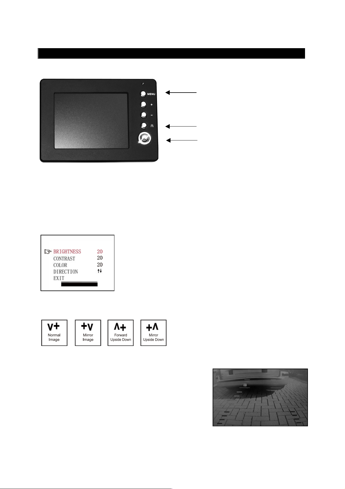
Menu Schalter
Wenn Sie den Schalter „Menu“ drücken, erscheint auf dem Monitor wie folgt:
Drücken Sie den “Menu” Schalter wiederholt um Helligkeit
(brightness), Kontrast (contrast), Farbe (Color) oder
Ausrichtung (Direction) des Bildes einzustellen.
Drücken Sie “+” oder “-“um die Einstellungen zu korrigieren.
Mit „+“ erhöhen Sie die Einstellung, mit “-„ verringern Sie die
Einstellung.
Um die Ausrichtung des Monitor-Bildes zu ändern, drücken Sie den “Menu” Schalter bis
“Direction” erscheint. Wenn Sie jetzt „+“ oder „-„ wiederholt drücken, sind mehrere
Bildschirm-Einstellungen verfügbar. Die
verschiedenen Ansichten ermöglichen es
Ihnen, die Kamera und den Monitor in jeder
Position zu befestigen und stets das richtige
Bild auf dem Monitor zu sehen.
Um das “Menu” zu verlassen, wählen Sie “EXIT” auf dem Bildschirm.
Hinweis-Schalter
Dieses Kamera System hat die Option, Ihnen einen
Abstands-Hinweis auf dem Display anzuzeigen. Hier
können Sie visuell den Abstand zwischen dem Objekt
hinter Ihrem Fahrzeug und Ihrem Fahrzeug erkennen.
Mit Druck auf den „Hinweis“ Schalter können Sie diese
Option an- und ausschalten.
Hinweis Schalter
Menu Schalter
Power Schalter
Page 7

7
TECHNISCHE SPEZIFIKATION
Kamera
Betriebsspannung
12V DC
Stromverbrauch
<150mA
Bildaufnahme
CMOS
Pixel
640x480
Bildauflösung
>330
Kabelloser Transmitter
Übertragungsdistanz (frei)
>80m
Betriebsspannung
12V DC
Stromverbrauch min.
<40mA
Stromverbrauch max.
<350mA
Sichtbarer LCD Monitor
3,5 Zoll (8,9 cm)
Pixel Bildschirm
320x240
Temperatur bei Gebrauch
-10 to +45 Grad Celsius
UMWELTSCHUTZ
GARANTIE
Linse 2,4mm / F2,1
Übertragungsfrequenz 2414MHz
LCD Monitor
Unbrauchbare oder defekte elektronische Produkte dürfen nicht mit dem
Hausmüll entsorgt worden. Bitte entsorgen Sie diese Geräte an den dafür
vorgesehenen Entsorgungsstellen oder fragen Sie Ihren Fachhändler.
ProUser gewährt eine Garantie von 2 Jahren ab Kaufdatum. Die Garantie ist nicht
übertragbar. Garantie wird gewährt auf Verarbeitungsmängel und Materialschäden. In
Garantiefällen senden Sie bitte das Gerät mit dem Kaufbeleg an Ihren Händler oder an
ProUser. Die Garantie erlischt, wenn das Gerät beschädigt wurde, wenn Bedienungsfehler
vorliegen oder bei unfachmännischer Reparatur durch nicht autorisierte Personen. Bei
anerkannter Garantie wird ProUser das Gerät reparieren oder Ersatz leisten. ProUser ist
nicht verantwortlich zu machen für Folgeschäden oder sonstige Unannehmlichkeiten.
Page 8
8
GB
INTRODUCTION
IMPORTANT SAFETY INSTRUCTIONS
PARTS
The RVC3610P is member of the family of advanced car back-up systems manufactured
by ProUser.
The Wireless Back-up Camera and Monitor, when used as described, will improve your
ability to see behind your car, camper, trailer, or mini-van. We have taken numerous
measures in quality control to ensure that your product arrives in top condition, and will
perform to your satisfaction.
Please carefully read and follow the following safety and operating instructions.
Before You Install
If you are not confident working with 12 volt DC vehicle wiring, removing and reinstalling
interior panels, carpeting, dashboards or other components of your vehicle, contact the
vehicle’s manufacturer, or consider having the camera system professionally installed.
Interference
This device, as well as all other wireless devices, may be subject to interference.
Interference may be caused by cell phones, Bluetooth headsets, Wi-FI routers, power
lines and other various electrical equipment, etc.
Repair
The camera system should not be opened. Any attempt at modification or repair by the
user will entail the loss of your guarantee.
1. Monitor and mounting Arm 2. Camera with mounting plate
3. Transmitter Box 4. Mounting Accessories 5. Monitor Power Cable
6. Transmitter Box Power Cable
Page 9

9
INSTALLATION
These instructions do not apply to all vehicles. They are only meant as a general
guide due to the number of different makes & models. For vehicle specific
questions contact your vehicle’s manufacturer.
Camera installation
There are several ways to mount the camera on the back of your car. But the most
convenient is to mount it near the license plate of the car. Supplied is one mounting plate
that can be fixed behind the license plate, and the mounting plate have been installed in
the camera.
The camera is tiltable, camera angle can be adjusted manually on vertical direction.
sure that its field of view and detection are not obstructed.
Make
At some type of cars it is not possible to mount the camera near the license plate. You
may have to find another spot at the back of your car to mount the camera.
1. Remove the rear license plate, and then loosen the license plate bolts/screws.
2. Position the supplied mounting plates (with camera together) behind the license plate
bracket. Secure both license plate bracket and mounting plates with the license plate
bracket bolts/screws.
3. Mount the license plate on the license plate bracket.
Page 10
10
4. Choose a routing path for the camera’s power cable through the vehicle’s body to the
reverse light circuit. If in doubt, seek professional installation assistance.
5. Some vehicles may have a hole available to pass the wire through, such as where the
license plate light is mounted, or you can drill a hole close to where the power cable
is attached to the camera. Once you have chosen where the cable will enter the
vehicle’s body, remove the camera. If you are able to use an existing opening, skip
the next two steps.
6. Before you drill a hole you MUST CHECK and see WHAT IS BEHIND WHERE YOU ARE
DRILLING. If there are any vehicle components, such as electrical parts or fuel
system components behind where you are drilling, you must take whatever
precaution is necessary not to damage them. Remove the license plate and camera
before drilling.
7. After you have drilled the hole, insert the supplied grommet, then pass the camera
cables through the grommet into the vehicle. You must use the grommet to prevent
the metal edge of the hole from cutting the camera cable.
8. Mount the transmitter box inside the trunk. Connect the camera’s power cable and
the transmitter box power cable to the transmitter box.
9. Next you’ll need to find the vehicle’s reverse lights. Turn the vehicle’s ignition key to
the accessory position, engage the parking brake and put the car in reverse. Look at
the vehicle’s tail lights to see where the reverse lights are located, they are the white
lights. To locate the reverse light’s 12V+ wire it will be necessary to gain access to
the rear of the vehicle’s tail light. For help locating the vehicle’s reverse light circuit
contact your vehicle’s manufacturer for vehicle specific wiring diagrams.
10. Once you have located the reverse light circuit you will have to route the transmitter
box power cable to that location. You must securely fasten the power cable to prevent
it from being caught on any vehicle component such as the trunk hinge. Never route
the cable on the outside of the vehicle!
11. The reverse light sockets on most vehicles
have two wires connected to the. Usually
the negative wire is black and the positive
wire is a colored wire. If you are uncertain
about the wiring, you can use a 12 volt
multimeter available at most auto parts
stores to determine which is the positive
wire. Follow the manufacturer’s
instructions for the safe use of the
multimeter.
12. After determining which wire is the
positive and which is the negative, turn
off the ignition key, then remove the battery’s negative cable.
13. Splice the red wire using the supplied in-line wire connectors to the reverse light’s
positive (+) wire. Use a set of slip joint pliers to squeeze the TAP and insure good
connection.
14. Next splice the black wire of the transmitter box power cable to the reverse light’s
negative (-) wire or ground.
15. Replace the reverse light bulb, and then re-install the light socket. Secure all the
wires with cable ties or electrical tape.
16. Re-attach the negative battery cable to the battery.
Page 11

11
Monitor Installation
When choosing a location to mount the monitor, make sure the
monitor is in an area that will not obstruct your vision while driving.
1. Before mounting the monitor, clean the mounting surface well.
2. Position the suction mount to the smooth surface which suits
your requirement.
3. Press the suction cap against the smooth surface and press the
lock down to attach and fix the mount to the surface.
4. Snap in the monitor to the suction mount.
5. Adjust the mounting arms to suit your view angle to the monitor and tighten the
screws on the mount to fix the position.
6. Route the power cable to the vehicle’s cigarette lighter socket/12V power outlet. The
cable must not interfere with the safe operation of the vehicle.
7. Insert the small 12 Volt DC plug of the power cable into the right side of the monitor.
8. Plug the 12 Volt cigarette lighter plug into the vehicle’s cigarette lighter socket.
To maximize the effectiveness of the suction mount, it is recommended that the
application be performed under the following conditions:
• Surface temperature should be between 21 and 38 degrees Celsius.
• Application below 10 degrees should be avoided.
• Application should not occur in direct sunlight.
Mounting should be protected from exposure to direct sunlight for a period of 24 hours.
NOTE: UNDER EXTREME BRIGHT LIGHT CONDITIONS, THE SCREEN IMAGE MAY TAKE A
FEW SECONDS TO STABLIZE. PLEASE WAIT UNTIL THE IMAGE HAS STABLIZED BEFORE
BACKING UP.
System testing
1. Reattach the vehicle’s negative battery cable.
2. Turn the ignition key to the accessory position, do not start the vehicle.
3. Engage the parking brake, and then put the shifter in the reverse position.
4. Look at the monitor, if the image does not match your rear view mirror press the
Image Orientation button on the monitor to correct the image.
5. After testing the unit and you are satisfied with the route you have chosen for the
cabling, you must permanently install it.
6. Route all wires behind interior panels or under carpeting so they are hidden. Use
supplied cable ties to neatly gather any excess wire.
Page 12
12
OPERATION
The monitor will automatically turn on when the vehicle is in reverse gear.
There are 5 control buttons available for users to have their controls:
Power button
Press the POWER button to supply power to the monitor. When the monitor image is on,
the blue LED will be lit. If there is power to the monitor, but the monitor image is OFF,
the blue LED will blink on and off. When the monitor power is off, no picture can appear
on the screen and the blue LED will be off.
Menu button
Press the Menu button to enter the menu screen as shown below:
Repeat pressing the Menu button to select Brightness,
contrast, colour or direction of the picture.
Press the + button or – button to adjust settings within the
control selected. Press the + button to increase the value and
press the – button to decrease the value.
To change the orientation of the screen image, press the menu button until direction is
selected. By pressing the + or - button repeatedly, different screen orientations will be
available. These different views allow you to
mount the camera and monitor in any
position with keeping the right picture on the
monitor.
To exit the menu screen, select exit on the screen.
Guideline button
This camera system has the option to show distanceguidelines on the display. This helps you to visually see
the distance between the objects behind your car. By
pressing the guideline button, you can switch this option
on and off.
Guideline button
Menu button
Power button
Page 13
13
TECHNICAL SPECIFICATIONS
Operating Voltage
12V DC
Current consumption
<150mA
Image sensor
CMOS
No. of pixel
640x480
Resolution
>330
Optical lens
2,4mm / F2,1
Wireless transmitter
Transmission frequency
2414MHz
RF transmission distance (open space)
>80m
LCD monitor
Operation Voltage
12V DC
Operation Current
<350mA
LCD display screen size
3,5 inch (8,9 cm)
Operation temperature
-10 to +45 degree Celsius
ENVIRONMENTAL PROTECTION
WARRANTY
Camera
Standby Current <40mA
No. of pixel 320x240
Waste electrical products should not be disposed of with household waste.
Please recycle where facilities exist. Check with your local authority or
retailer for recycling advice.
ProUser warrants this product for a period of 2 years from the date of purchase to the
original purchaser. Warranty is not transferable. Warranty covers defect against
workmanship and materials only. To obtain warranty service, please return the unit to
the place of purchase or authorized ProUser dealer together with your proof of purchase.
The warranty is void if the product has been damaged or not used as described in this
manual. Warranty is void if a non-authorized repair has been performed. ProUser makes
no other warranty expressed or implied. ProUser is only responsible for repair or
replacement (at ProUser Discretion) of the defective product and is not responsible for
any consequential damage or inconvenience caused by the defect.
Page 14

14
FR
INTRODUCTION
IMPORTANT - CONSIGNES DE SECURITE
CONTENU
Le RVC3610P fait partie de la gamme de cameras de recules sans fils de dernières
génération fabriqués par ProUser
Félicitations! Le système améliorera considérablement votre vue vers l'arrière de votre
voiture, camping-car, caravane ou remorque, si vous l'utilisez comme décrit ci-dessous.
Nous avons testé sérieusement ce système pour être sûr que vous pourrez vous en servir
sans problèmes et que vous serez entièrement satisfait de son fonctionnement.
S’il vous plait, veuillez lire attentivement cette notice et suivre les instruction.
Avant l’installation
Si vous ne vous sentez pas capable d’intervenir sur le circuit électrique 12 volt DC d'une
voiture, de démonter et remonter les panneaux intérieurs, la moquette, le tableau de
bord ou d'autres pièces de votre voiture, on vous conseille de prendre contact avec votre
concessionnaire, votre garage ou centre auto pour faire installer ce système de façon
professionnelle par une personne qualifié.
Interférence
Comme tous les systèmes sans fil, le pourra être troublé dans son fonctionnement par
des portables, des casques bluetooth, des systèmes GPS, des câbles électrique, ou par
d'autres appareils électriques.
Réparation
La camera et le moniteur ne doivent jamais êtres ouvert. Autrement l’utilisateur pert la
garantie.
1. Moniteur et bras de fixation 2. Camera avec plaque de fixation
3. Boîtier transmetteur 4. Accessoires de fixation 5. Câble d’alimentation
6. Câble d’alimentation transmetteur
Page 15

15
INSTALLATION
C’est instructions d’installation ne s’appliquent pas à tous les véhicules mais à
la majorité. Sur certains véhicules il n’est pas possible de fixer la caméra sur la
plaque d’immatriculation. Dans ce cas contacter votre concessionnaire ou votre
garagiste afin de trouver un autre endroit approprié.
Camera installation
Il y’a différentes manières de fixer la camera de recule. La plus pratique étant à
proximité de la plaque d’immatriculation du véhicule. Nous fournissons 1 plaque de
montage qui se fixe derrière la plaque d’immatriculation. La caméra de recule peut se
fixer sur ces plaques de montages. La caméra est inclinable, l’angle de vue peut donc
être ajusté manuellement verticalement. Assurez vous que le champ de vue de la camera
est libre.
Sur certains véhicules il n’est pas possible de fixer la camera à l’aide des plaques de
montages fournies. Alors il vous faut trouver un autre endroit à l’arrière du véhicule pour
fixer la caméra.
1. Enlevez la plaque d’immatriculation (et porte plaque) en la dévissant ou en enlevant
les rivets.
2. Placez la plaque de montage (avec la caméra) derrières la plaque d’immatriculation
puis fixez les solidairement avec la plaque d’immatriculation. Par vis ou rivets.
3. Fixer la plaque d’immatriculation sur le support de plaque.
Page 16

16
4. Choisissez un chemin d’accès pour le câble d’alimentation de la camera dans
l’intérieure du coffre de votre véhicule afin de le brancher sur le faisceau électrique de
l’ampoule de marche arrière. Si vous avez des doutes, consultez un professionnel.
Votre garagiste, centre auto ou concessionnaire.
5. Certains véhicules ont d’origine un trou à cet effet, qui vous permet de faire passer le
câble d’alimentation. Dans le cas contraire il vous faut percer un trou. De préférence
derrière la plaque d’immatriculation. Une fois que vous avez identifié l’endroit retirez
la camera. Si vous avez la possibilité d’utiliser un trou de passage existant alors vous
pouvez sauter le 2 points suivants.
6. Avant de PERCER un TROU, vous devez VERIFIER CE QU’IL Y’A DERRIERE, à
l’intérieur de votre véhicule. Si il y’à des câbles, composant ou autre objet, alors vous
devez choisir un autre endroit pour percer le trou. Enlever la plaque et la caméra
avant de percer.
7. Après avoir percer le trou, veuillez insérer la bague de passage fournie. Elle protège
votre câble d’alimentation contre les bords tranchants.
8. Maintenant fixez le boîtier transmetteur dans votre coffre. Raccordez le câble
d’alimentation à votre caméra puis au boîtier de transmission.
9. En suite vous devez identifier l’ampoule de marche arrière (généralement le feu
blanc). Tournez la clef de contact de votre véhicule, serrez le frein à main puis
enclencher la marche arrière. Regardez à l’arrière de votre véhicule ou demander à
une autre personne de regardez quelle ampoule s’allume. Trouvez le câble qui
alimente l’ampoule de marche arrière. Pour se faire vous devez retournez à l’arrière
de votre véhicule. Si vous n’y parvenez pas alors consultez un professionnel, votre
garagiste ou concessionnaire.
10. Une fois le circuit électrique le l’ampoule de marche arrière identifié, vous devez
passer le câble d’alimentation du boîtier transmetteur vers le câble électrique de
l’ampoule. Fixez le de manière très sûr. Le câble ne doit pas pouvoir être arraché par
des objets transportés dans le coffre ultérieurement. Ne jamais faire passer le câble
à l’extérieur du véhicule!
11. La plus part des ampoules de marche
arrière sont alimenté par 2 fils électriques.
En général le noir est le négatif et le rouge
le positif. Dans le doute contrôlez avec un
voltmètre 12V (disponible dans la majorité
des magasins de bricolage) ou allez
consulter un professionnel. Suivez les
instructions de la notice du voltmètre.
12. Après avoir déterminé les polarités des fils
électriques veuillez retirer la clef de
contacte puis déconnectez la cosse (-)
négative de votre batterie de démarrage (la batterie se situe souvent dans le
compartiment moteur du véhicule), ceci afin d’être sûr qu’il n’y ai plus de courant
dans les circuits électrique. Pour trouver la batterie veuillez consulter la notice de
votre véhicule.
13. Fixez le fil rouge du câble de l’émetteur à l’aide du connecteur rouge dans le câble
positif (+) des feux de recule. Prenez une pince pour faire entrer la languette
métallique et pliez/accrochez ensuite le couvercle rouge en plastique.
14. Puis répétez l’opération (14) avec le câble négatif (-) (souvent noir).
15. Replacez l’ampoule de marque arrière et le cache puis sécuriser les câbles de sorte
qu’il de puisse pas être accrochés par un objet transporté dans le coffre. Pour
sécuriser les câbles, veuillez utiliser des serre-fils ou du ruban adhésif pour
installations électriques.
16. Reconnecté la cosse négative à votre batterie.
Page 17

17
Installation du moniteur
Choisissez un endroit qui ne puisse pas gêner la visibilité du
conducteur ou d’une manière générale gêner la conduite.
1. Avant de fixer la ventouse, veuillez bien nettoyer l’endroit ou vous
voulez la fixer.
2. Positionner la ventouse sur une surface parfaitement plane, lisse et
propre.
3. Appuyer la ventouse sur la surface et faite basculer le loquet.
4. Enficher le moniteur sur la fixation.
5. Ajuster l’orientation du moniteur puis serer la vis.
6. Passer la câble d’alimentation entre le moniteur et votre prise allume cigare de sorte
qu’il ne puisse en aucun cas gêner le conducteur. Même si il devait tomber.
7. Insérer le petit connecteur dans le côté droit du moniteur, c’est le câble
d’alimentation 12V.
8. Brancher la prise d’alimentation dans la prise allume cigare de votre véhicule.
Pour optimiser la fixation du moniteur sur le tableau de bord il est recommandé:
• De l’installer lors de températures ambiantes de 21 à 38 C°.
• De ne pas le coller lors de températures sous 10 C°.
• Ne pas exposer la fixation directement au soleil.
• De bien dégraisser l’endroit de fixation.
Protéger l’installation des rayons du soleil pendant 24 heures.
REMARQUE: lors d’une lumière ambiante très Claire, le moniteur nécessite un certain
temps d’adaptation.
Pour tester le système
1. Assurez vous que la cosse négative est branchée sur la batterie du véhicule.
2. Mettez le contact en tournant la clef, ne démarrez pas..
3. Serrez le frein à main puis engagez la marche arrière.
4. Regardez le moniteur, si l’image ne correspond pas à celle que vous voyez dans le
rétroviseur, veuillez appuyer sur la touché d’orientation de l’image.
5. Une fois le test effectué et si vous êtes satisfait du résultat, alors fixer définitivement
les câbles d’alimentation dans votre coffre.
6. Placez les câbles derrière les caches et moquettes de votre véhicule. Utilisez les
serres fils fournis pour fixer le surplus de câbles.
Page 18

18
FONCTIONEMENT
The monitor will automatically turn on when the vehicle is in reverse gear.
There are 5 control buttons available for users to have their controls:
Bouton POWER (M/A)
Appuyez sur le bouton POWER pour allumer le moniteur. Une LED s’éclaire quand l’image
apparaît. Si le moniteur est allumé mais sans image, alors la LED bleu clignote. Lorsque
le moniteur est éteint, pas d’image apparaît et la LED bleu ne s’allume pas.
Bouton MENU
Appuyer sur le bouton MENU pour entrer dans le menu comme démontré dans l’image cidessous:
Appuyer de nouveau sur le bouton MENU pour valider une sélection Brightness
(luminosité), contrast, colour ou direction l’image.
Appuyer sur + et – pour effectuer le réglage.
Pour quitter le menu, sélectionnez EXIT.
Bouton GUIDELINE (grille de graduation)
Cette camera de recule dispose d’un dispositif qui affiche
une graduation de distance sur le moniteur.
Ceci vous aide à évaluer la distance entre votre véhicule et
l’obstacle derrière votre véhicule. En appuyant sur le
bouton GUIDLINE vous activez et désactivez le dispositif.
Bouton grille de distance
Bouton menu
Bouton Marche / Arrêt
Page 19

19
CARACTERISTIQUES TECHNIQUES
Caméra
Alimentation
12V DC
Consommation
<150mA
Capteur
CMOS
Nombre. de pixel
640x480
Résolution
>330
Transmetteur sans fil
Porté (champ libre)
>80m
Alimentation
12V DC
Consommation en veille
<40mA
Consommation en fonctionnement
<350mA
Taille de l’écran LCD
3,5inch (8,9 cm)
Nombre. de pixel
320x240
Température de fonctionnement
-10 to +45 C°
CONSIGNES DE MISE A REBU
GARANTIE
Lentille 2,4mm / F2,1
Fréquence de transmission 2414MHz
Moniteur LCD
Les appareils électroniques ne doivent pas êtres mis à rebu avec les
ordures ménagères. Veuillez les porter au déchèteries prévues à cet effet.
Consultez votre revendeur ou votre mairie afin de connaître la procédure
de recyclage.
ProUser garantie ses produits pendant 2 ans à partir de la date d’achat originelle. La
garantie n’est pas transférable. La garantie en cas de panne couvre uniquement la main
d’œuvre et le matériel. Pour faire valoir la garantie veuillez retournez l’appareil à votre
revendeur ou représentant officiel ProUser accompagner de votre facture d’achat. La
garantie ne s’applique pas si l’appareil à été endommagé ou détourné de sont utilisation
initiale tel que décrite dans la notice d’utilisation. La garantie ne s’applique pas si il y’a eu
des tentatives de réparation non autorisées. ProUser ne s’engage sur aucun autre terme
de garantie. ProUser est responsable que de la réparation ou de l’échange du produit (à
la discrétion de ProUser) et non des dommages ou désagrément résultant du défaut et de
l’utilisation du produit.
Page 20

20
SK
ÚVOD
DÔLEŽITÉ UPOZORNENIA
PRÍSLUŠENSTVO
Výrobok RVC3610P patrí k rodine pokrokových kamerových systémov cúvania
automobilov.
Bezdrôtová kamera na cúvanie s monitorom vám pri náležitej obsluhe umožňuje vidieť za
váš automobil, príves alebo minivan. Pri kontrole kvality boli podniknuté viaceré
opatrenia s ohľadom na kvalitu, aby vám k vašej spokojnosti mohol byť dodaný top
produkt.
Dôkladne si prečítajte návod na obsluhu a riaďte sa bezpečnostnými pokynmi a
návodom na montáž.
Pred montážou
Ak ste si nie istí, že tento systém dokážete sami primontovať k 12 V napájaniu vo vašom
vozidle (vŕtanie otvorov, zloženie čalúnenia atď.), spojte sa s predajňou vášho
automobilu alebo autoservisom podľa vášho výberu. Tam môžete zadať zákazku na
profesionálnu montáž systému.
Porucha
Tento kamerový systém môže podliehať určitým poruchám rovnako, ako iné bezdrôtové
systémy. Poruchy môžu byť spôsobené prostredníctvom mobilných telefónov, technológie
bluetooth, slúchadiel, navigačných systémov a iných elektrických prístrojov.
Oprava
Tento kamerový systém sa nesmie otvárať! Pri akomkoľvek pokuse o opravu zanikne
záruka.
1. Monitor s upevňovacím ramenom 2. Kamera s upevňovacou doskou
3. Vysielač 4. Inštalačný materiál 5. 12 V kábel pre monitor
6. Sieťový kábel pre vysielač
Page 21

21
MONTÁŽ
Tento návod na obsluhu nie je možné použiť pre všetky vozidlá. Je všeobecnou
príručkou pre väčšinu vozidiel. V prípade otázok špecifických pre dané vozidlo
sa obráťte na výrobcu vášho automobilu.
Montáž kamery
Existujú rôzne možnosti na upevnenie kamery na zadnej strane vášho vozidla.
Najbežnejšie je upevnenie kamery v blízkosti štátnej poznávacej značky. Dodanú
montážnu dosku môžete upevniť za štátnu poznávaciu značku. Na túto montážnu dosku
sa môže namontovať kamera.
Kamera je vertikálne otočná, nastavte ju podľa príslušných daností.
Pri niektorých vozidlách nie je možné kameru pripevniť v blízkosti štátnej poznávacej
značky. Nájdite si iné miesto na zadnej časti vášho vozidla a kameru upevnite pomocou
dodaných skrutiek a matíc.
1. Z držiaka vyberte štátnu poznávaciu značku, potom uvoľnite skrutky držiaka
štátnej poznávacej značky a zložte ju.
2. Upevňovaciu dosku s kamerou umiestnite za držiakom štátnej poznávacej značky
a upevňovaciu dosku i držiak štátnej poznávacej značky pripevnite na vozidlo.
3. Štátnu poznávaciu značku pripevnite opäť na držiak poznávacej značky.
4. Následne si vyberte miesto, kadiaľ môžete viesť elektrický kábel kamery cez
karosériu vozidla k elektrickému káblu spätného svetla.
Page 22

22
5. Niektoré vozidlá majú v blízkosti značky otvor, cez ktorý sa môže kábel pretiahnuť.
Ak ho tam nemáte, musíte v blízkosti značky, tesne vedľa miesta, kde sa
nachádza kábel kamery, sami vyvŕtať otvor. Keď ste si stanovili miesto na otvor,
môžete kameru a štátnu poznávaciu značku vozidla znovu demontovať. Ak
použijete existujúci otvor, môžete dva nasledujúce kroky preskočiť.
6. Skôr ako začnete vŕtať, demontujte kameru a štátnu poznávaciu značku. PRED
VŔTANÍM SKONTROLUJTE, ČO SA NACHÁDZA NA ZADNEJ STRANE MIESTA, KDE
CHCETE VŔTAŤ! Postarajte sa napr. o to, aby tam neboli žiadne elektrické káble,
nádržky na tekutinu alebo vodiče. Rešpektujte všetky preventívne opatrenia!
7. Po vyvŕtaní otvoru upevnite do otvoru dodanú ochranu hrán, aby ste kábel
ochránili pred ostrým okrajom vyvŕtaného otvoru. Potom pretiahnite kábel kamery
do vnútra vozidla.
8. Vysielač pripevnite v priestore kufra vozidla. Kábel kamery a kábel vysielača
spojte s vysielačom.
9. Zapnite zapaľovanie vozidla (neštartujte!), zatiahnite ručnú brzdu a zaraďte
spiatočku. Potom sa pozrite na zadnú stranu vozidla, kde sa nachádzajú spätné
svetlomety (svetlá na cúvanie). Aby ste mohli nájsť káble spätného svetlometu,
musíte zadnú stranu osvetlenia zadnej strany vozidla otvoriť a lokalizovať
príslušné káble. Prípadne kvôli tomu vyhľadajte pomoc v predajni vášho vozidla
alebo autoservise podľa vášho výberu.
10. Keď ste príslušné káble našli, položte kábel vysielača na spájací bod. Postarajte sa
o to, aby bolo upevnenie kábla bezpečné a pevné, aby pri otváraní a zatváraní
zadnej kapoty nemohlo dôjsť k jeho poškodeniu. Kábel nikdy neinštalujte mimo
vozidlo!
11. Na zásuvke spätného svetlometu sú
upevnené dva drôty. Zvyčajne je
záporný drôt čierny a kladný je farebný.
Ak nie ste si istí, môžete pomocou 12 V
multimetra (kúpite v špecializovanom
obchode) skontrolovať, ktorý drôt je
kladný alebo záporný. Kvôli
bezpečnému použitiu sa riaďte návodom
na obsluhu multimetra.
12. Ak ste zistili, ktorý drôt je kladný alebo
záporný, vypnite zapaľovanie a
odstráňte záporný kábel vašej
autobatérie. Tak bude zabezpečené, že
v drôtoch nebude žiadny prúd.
13. Spojte červený drôt kábla vysielača s kladným drôtom spätného svetlometu.
Použite na to priložené káblové svorky. Svorky pevne stlačte dohromady pomocou
klieští a na tieto kontaktné miesta založte červené plastové krytky.
14. Potom spojte čierny drôt kábla vysielača so záporným drôtom spätného
svetlometu. (Aj tu použite káblové svorky)
15. Potom opäť zatvorte zadné svetlo (dbajte na to, aby bola nasadená žiarovka).
Používajte sťahovacie pásky na káble a špeciálne pásky (na spojenie káblov), aby
boli všetky drôty a káble bezpečne a pevne nainštalované!
16. Nakoniec znovu pripojte záporný kábel autobatérie.
Page 23
23
Montáž monitora
Keď ste našli vhodné miesto na upevnenie monitora,
ubezpečte sa, že vám počas jazdy nebude brániť vo výhľade.
1. Pred upevnením miesto dôkladne vyčistite.
2. Prísavku držiaka umiestnite na vami zvolenú plochu.
3. Prísavku pevne pritlačte k očistenému povrchu a sklopte páčku,
aby bola prísavka bezpečne a pevne umiestnená.
4. Monitor zasuňte do držiaka, ktorý sa nachádza na prísavke.
5. Rameno držiaka otočte a monitor nasmerujte do želanej polohy. Utiahnite skrutky.
6. Sieťový kábel položte k zapaľovaču cigariet. Kábel uložte tak, aby počas jazdy
nemohlo dôjsť k žiadnym obmedzeniam alebo prekážkam.
7. Malý 12 V konektor sieťového kábla zasuňte do otvoru na pravej strane monitora.
8. Druhý konektor kábla zasuňte do zapaľovača cigariet.
Aby sa zabezpečilo pevné držanie prísavky, odporúča sa jej použitie iba pri dodržaní
nasledujúcich predpokladov:
• Teplota povrchu by mala byť v rozmedzí od 21 do 38 stupňov Celzia.
• Malo by sa zabrániť použitiu pri teplote nižšej ako 10 stupňov Celzia.
• Malo by sa zabrániť použitiu pri slnečnom žiarení.
Upevnenie by malo byť chránené pred priamym slnečným žiarením.
POZOR: V PRÍPADE EXTRÉMNE OSTRÉHO SVETLA POTREBUJE MONITOR
NIEKOĽKO SEKÚND, ABY SA TÝMTO SVETELNÝM POMEROM PRISPÔSOBIL. S
CÚVANÍM POČKAJTE, KÝM NIE JE OBRAZ STABILIZOVANÝ.
Test systému
1. Skontrolujte, či ste záporný kábel autobatérie znovu pripevnili.
2. Zapnite zapaľovanie vozidla (neštartujte).
3. Zatiahnite ručnú brzdu a zaraďte spiatočku.
4. Pozrite sa na monitor. Ak tento obrázok nie je identický s tým, čo vidíte v spätnom
zrkadle, stlačte na monitore tlačidlo zamerania obrazu (Image Orientation), aby sa
obraz mohol skorigovať.
5. Keď ste test ukončili k svojej spokojnosti, uložte všetky voľne ležiace káble.
6. Všetky káble uložte za čalúnenie vozidla alebo pod koberce vo vozidle tak, aby neboli
vidieť. Používajte priložené sťahovacie pásky na káble, aby sa káble dôkladne spojili
dohromady.
Page 24

24
OBSLUHA
Monitor sa automaticky zapne, keď sa zaradí spiatočka. Ďalej je na monitore k dispozícii
5 kontrolných tlačidiel.
Spínač Power
Stlačte spínač Power, aby mohol byť monitor napájaný prúdom. Keď je k dispozícii obraz,
rozsvieti sa modrá LED dióda. Keď má monitor prúd, ale obraz je vypnutý, bliká modrá
LED dióda. Keď je monitor vypnutý, nezobrazuje sa žiadny obraz a modrá LED dióda je
vypnutá.
Spínač menu
Keď stlačíte spínač „Menu“, objaví sa na monitore nasledovné:
Spínač “Menu” stláčajte opakovane, aby ste mohli nastaviť
svetlosť (brightness), kontrast (contrast), farbu (color)
alebo nasmerovanie (direction) obrazu.
Kvôli úprave nastavenia stláčajte “+” alebo “-“. Pomocou
„+“ zvyšujete nastavenie, pomocou “-„ ho znižujete.
Aby sa mohlo zmeniť nasmerovanie obrazu monitora, stlačte spínač “Menu”, kým sa
neobjaví “Direction”. Keď teraz opakovane stlačíte „+“ alebo „-“, bude k dispozícii
viacero nastavení monitora. Rôzne pohľady
vám umožňujú kameru a monitor upevniť v
každej polohe a vždy vidieť na monitore ten
správny obrázok.
Aby ste mohli opustiť “Menu”, zvoľte na monitore “EXIT”.
Spínač s upozornením
Tento kamerový systém má možnosť zobraziť na displeji
upozornenie na vzdialenosť. Tu môžete vizuálne
rozpoznať vzdialenosť medzi objektom za vaším
vozidlom a vaším vozidlom. Stlačením spínače
„Hinweis“ (Upozornenie) môžete túto možnosť zapnúť a
vypnúť.
Spínač s upozornením
Spínač menu
Spínač Power
Page 25

25
TECHNICKÁ ŠPECIFIKÁCIA
Kamera
Prevádzkové napätie
12V DC
Spotreba prúdu
<150mA
Snímanie obrazu
CMOS
Pixely
640x480
Rozlíšenie obrazu
>330
Bezdrôtový vysielač
Prenosová vzdialenosť (voľná)
>80m
Prevádzkové napätie
12V DC
Min. spotreba prúdu
<40mA
Max. spotreba prúdu
<350mA
Viditeľný LCD monitor
3,5 palcový (8,9 cm)
Pixely obrazovky
320x240
Teplota pri použití
-10 až +45 stupňov Celzia
OCHRANA ŽIVOTNÉHO PROSTREDIA
ZÁRUKA
Šošovka 2,4mm / F2,1
Frekvencia prenosu 2414MHz
LCD monitor
Nepoužiteľné alebo chybné elektronické výrobky sa nesmú likvidovať
prostredníctvom odpadu z domácností. Tieto prístroje likvidujte na
miestach na to určených alebo sa informujte u vášho špecializovaného
predajcu.
ProUser poskytuje záruku v trvaní 2 rokov od dátumu kúpy. Záruka nie je prenosná.
Záruka sa poskytuje na nedostatky vyplývajúce zo spracovania a materiálu. V záručných
prípadoch pošlite váš prístroj aj s dokladom o kúpe vášmu predajcovi alebo firme ProUser.
Záruka zanikne, ak bol prístroj poškodený, v prípade chyby v obsluhe alebo neodbornej
opravy neautorizovanými osobami. V prípade uznanej záruky firma ProUser prístroj
opraví alebo vám poskytne náhradu. Firma ProUser nie je zodpovedná tak konať pri
následných škodách alebo iných nepríjemnostiach.
Page 26
26
14
x x x
x
EG – Konformitätserklärung
EU – Declaration of Conformity
Hiermit bestätigen wir, dass das nachfolgend bezeichnete Gerät den angegebenen Richtlinien
entspricht.
We herewith confirm that the appliance as detailed below complies with the mentioned directives.
Artikelbezeichnung: Wireless Back-up Camera System
Article description: Kabelloses Rückfahrkamerasystem
Artikelnummer: 16238 / 20130
Article number:
Type: RVC3610P
Firmenanschrift: Pro-User Europe GmbH, Seestrasse 19, 83253 Rimsting, Germany
Company address:
Einschlägige EG-Richtlinien / governing EU-directives / directives CE concernées:
1. Elektromagnetische Verträglichkeit (EMV) 2. Niederspannungs-Richtlinie
Electromagnetic compatibility (EMC) Low voltage directive
2004/108/EC 2006/95/EC
3. Funkanlagen und 4. ROHS Richtline
Telekommunikationsendeinrichtungen
Radio and Telecommunication Terminal Equipment 2011/65/EU
ROHS directive
R&TTE 1999/5/EC
Harmonisierte EN-Normen
/ harmonised EN- Standarts
Dieser Artikel entspricht folgenden, zur Erlangung des CE-Zeichens erforderlichen Normen:
The article complies with the standards as mentioned below wich are necessary to obtain the CE-symbol:
Zu 1.
EN55022:2010+AC:2011
EN55024:2010
Zu 2.
EN 60950-1:
2006+A11:2009+A1:2010+A12:2011
Zu 3.
EN 300 440-1 V1.6.1:2010
EN 300 440-2 V1.4.1:2010
EN 301 489-1 V1.9.2:2011
EN 301 489-3 V1.4.1:2002
Unterschrift / Signature & Firmenstempel / Company Chop
Stellung im Betrieb / Position: Geschäftsführer
Ausstellungdatum / Date of issue: 10.01.2014
Pro-User Europe GmbH, Seestrasse 19, 83253 Rimsting, Germany
Page 27

27 28
Page 28

www.pro-user.com
 Loading...