


 WIRELESS REAR VIEW CAMERA SYSTEM WITH MIRROR DISPLAY & BLUETOOTH 2.1 HAND FREE SYSTEM
 KABELLOSES INNENSPIEGEL RÜCKFAHR- KAMERA-SYSTEM & BLUETOOTH 2.1
 CAMERA DE RECUL SANS FILS & KIT
MAIN-LIBRE BLUETOOTH 2.1  DRAADLOOS CAMERASYSTEEM
& BLUETOOTH 2.1
With built-in 3,5 inch monitor mit integriertem 3,5” Monitor Avec écran 3,5 pouces intégré met 3,5 inch monitor
APB120
1
INTRODUCTION
The Pro-User APB120 is member of the family of advanced car Rear view mirror back up & Bluetooth 2.1 hand free systems manufactured by Pro User International Ltd.
The Pro-User Wireless Rear view mirror Back-up Camera & Bluetooth 2.1 hand free systems, when used as described, will improve your ability to see behind your car, camper, trailer, or mini-van. We have taken numerous measures in quality control to ensure that your product arrives in top condition, and will perform to your satisfaction.
Please carefully read and follow the following safety and operating instructions.
IMPORTANT SAFETY AND PRIVACY
Before You Install
If you are not confident working with 12 volt DC vehicle wiring, removing and reinstalling interior panels, carpeting, dashboards or other components of your vehicle, contact the vehicle’s manufacturer, or consider having the camera system professionally installed.
Interference
All wireless devices are susceptible to interference or may cause interference, which could affect usability.
Privacy
Upon detection of new mobile device (different ID) pairing, the Bluetooth system will automatically erase all information concerning the previous linked mobile device, including download phonebook, call log, etc.
Repair
The camera system should not be opened. Any attempt at modification or repair by the user will entail the loss of your guarantee.
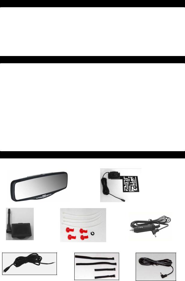
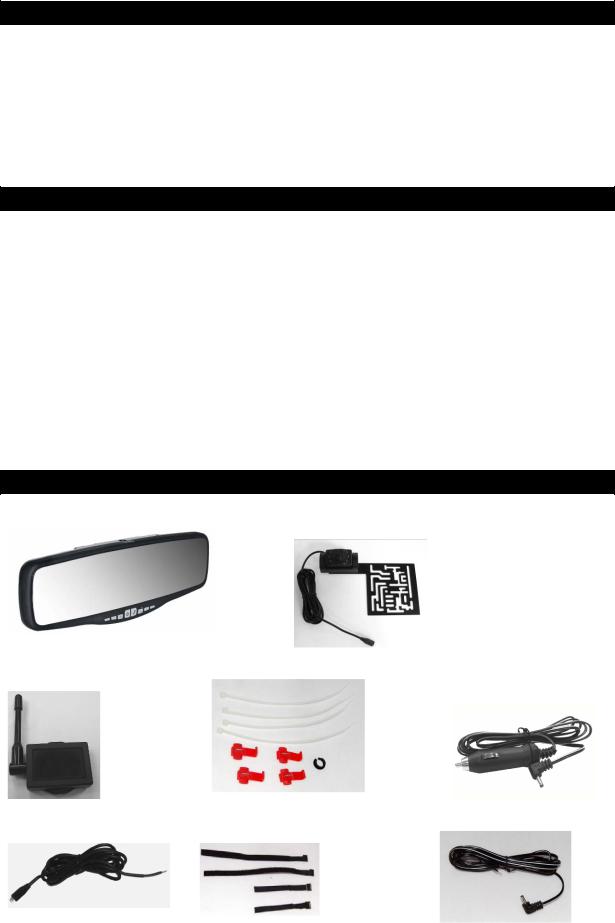
PARTS
1. Rear View Mirror |
2. Camera with mounting plate |
|||
|
|
|
|
|
|
|
|
|
|
3. Transmitter Box |
4. Mounting Accessories |
5. Mirror cigarette DC plug |
|||||
|
|
|
|
|
|
|
|
|
|
|
|
|
|
|
|
|
|
|
|
|
|
|
|
|
|
|
|
|
|
|
|
6. Transmitter Box Power Cable 7.Mirror mounting magic tape 8. Mirror power cable
2
INSTALLATION
These instructions do not apply to all vehicles. They are only meant as a general guide due to the number of different makes & models. For vehicle specific questions contact your vehicle’s manufacturer.
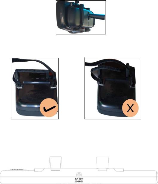
Camera installation
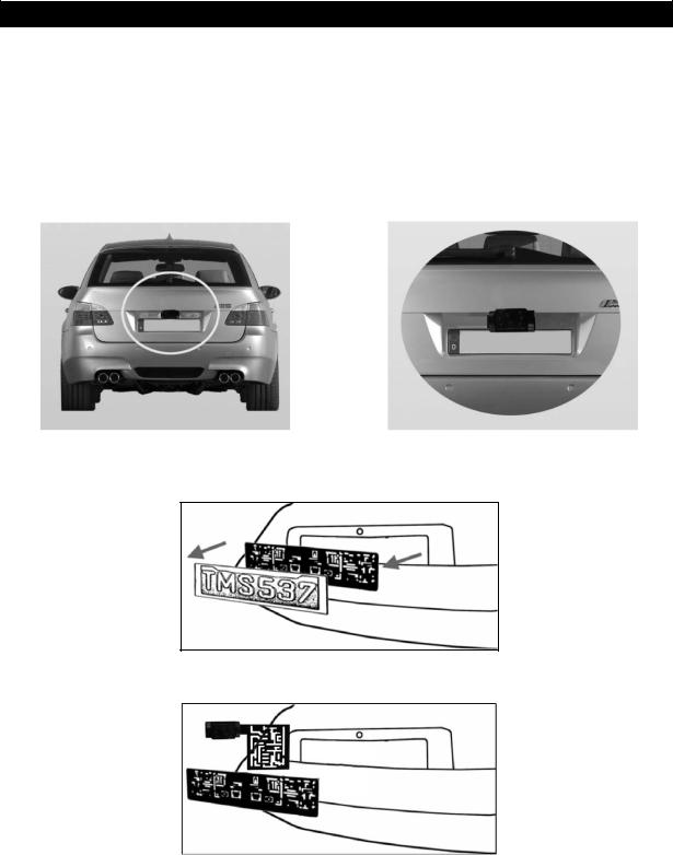
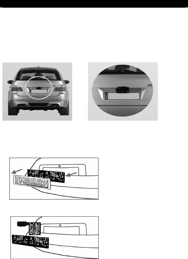
There are several ways to mount the camera on the back of your car. But the most convenient is to mount it near the license plate of the car. Supplied is one mounting plate that can be fixed behind the license plate, and the mounting plate have been installed in the camera.
The camera is tiltable, camera angle can be adjusted manually on vertical direction. Make sure that its field of view and detection are not obstructed.
At some type of cars it is not possible to mount the camera near the license plate. You may have to find another spot at the back of your car to mount the camera.
1. Remove the rear license plate, and then loosen the license plate bolts/screws.
2.Position the supplied mounting plates (with camera together) behind the license plate bracket. Secure both license plate bracket and mounting plates with the license plate bracket bolts/screws.
3
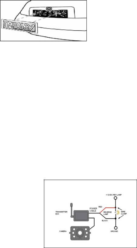
3. Mount the license plate on the license plate bracket.
4.Choose a routing path for the camera’s power cable through the vehicle’s body to the reverse light circuit. If in doubt, seek professional installation assistance.
5.Some vehicles may have a hole available to pass the wire through, such as where the license plate light is mounted, or you can drill a hole close to where the power cable is attached to the camera. Once you have chosen where the cable will enter the vehicle’s body, remove the camera. If you are able to use an existing opening, skip the next two steps.
6.Before you drill a hole you MUST CHECK and see WHAT IS BEHIND WHERE YOU ARE DRILLING. If there are any vehicle components, such as electrical parts or fuel system components behind where you are drilling, you must take whatever precaution is necessary not to damage them. Remove the license plate and camera before drilling.
7.After you have drilled the hole, insert the supplied grommet, then pass the camera cables through the grommet into the vehicle. You must use the grommet to prevent the metal edge of the hole from cutting the camera cable.
8.Mount the transmitter box inside the trunk. Connect the camera’s power cable and the transmitter box power cable to the transmitter box.
9.Next you’ll need to find the vehicle’s reverse lights. Turn the vehicle’s ignition key to the accessory position, engage the parking brake and put the car in reverse. Look at the vehicle’s tail lights to see where the reverse lights are located, they are the white lights. To locate the reverse light’s 12V+ wire it will be necessary to gain access to the rear of the vehicle’s tail light. For help locating the vehicle’s reverse light circuit contact your vehicle’s manufacturer for vehicle specific wiring diagrams.
10.Once you have located the reverse light circuit you will have to route the transmitter box power cable to that location. You must securely fasten the power cable to prevent it from being caught on any vehicle component such as the trunk hinge. Never route the cable on the outside of the vehicle!
11.The reverse light sockets on most vehicles have two wires connected to them. Usually the negative wire is black and the positive wire is a colored wire. If you are uncertain about the wiring, you can use a 12 volt multimeter available at most auto parts stores to determine which is the positive wire. Follow the manufacturer’s instructions for the safe use of the multimeter.
12.After determining which wire is the positive and which is the negative, turn off the ignition key, then remove the battery’s negative cable.
4
13.Splice the red wire using the supplied in-line wire connectors to the reverse light’s positive (+) wire. Use a set of slip joint pliers to squeeze the TAP and insure good connection.
14.Next splice the black wire of the transmitter box power cable to the reverse light’s negative (-) wire or ground.
15.Replace the reverse light bulb, and then re-install the light socket. Secure all the wires with cable ties or electrical tape.
16.Re-attach the negative battery cable to the battery.
Rear View Mirror Installation
When mounting the mirror, please double check the width of your car’s rear view mirror≤ 80mm to avoid cannot be installed.
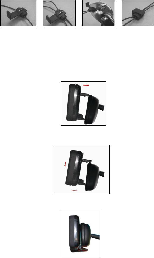
1. Place the spring loaded top clips underneath the car’s existing rear view mirror.
2.Press down the mirror extend to the bottom clips, then tilt the mirror towards the existing rear view mirror.
3.Left the spring loaded clips close around the mirror. Adjust the Rear View Mirror for the best rear view.
5
4. Tighten the magic tape to fix the position.
Remark: Please make sure the male and female of the magic tape are matched perfectly before you connect the metal buckle of the magic tape to the main unit, once you connect them, you can not pull the metal buckle out.
5. Choose a Location and Install Power Cable as below alternative methods showed in the pics:
a.Choose a location on windshield or dashboard of your car, where does not obstruct your vision.
b.Insert the small 12 Volt DC plug of the power cable into the top of the mirror.
c.Connect the Cigarette DC plug cable (provided) with the cigarette lighter socket/12V power outlet of vehicle.
Remark: The cable must not interfere the safe operation of the vehicle.
6

For professional installation, refer to the illustration above, if doubt please seek professional assistant.
7
NOTE: UNDER EXTREME BRIGHT LIGHT CONDITIONS, THE SCREEN IMAGE MAY TAKE A FEW SECONDS TO STABLIZE. PLEASE WAIT UNTIL THE IMAGE HAS STABLIZED BEFORE BACKING UP.
Back up System testing
1Reattach the vehicle’s negative battery cable.
2Turn the ignition key to the accessory position, do not start the vehicle.
3Engage the parking brake, and then put the shifter in the reverse position.
After testing the unit and you are satisfied with the route you have chosen for the cabling, you must permanently install it.
Route all wires behind interior panels or under carpeting so they are hidden. Use supplied cable ties to neatly gather any excess wire.
OPERATION
The built-in LCD display beneath the mirror will automatically turn on and enter back up mode when the vehicle is in reverse gear, otherwise, the device will turn into Bluetooth hand free mode, in Bluetooth mode, if no mobile device was found in 30 sec, system will enter sleep mode.
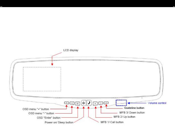
There are 8 control buttons and a volume dial available for users to have their controls:
Power on/Sleep button
Press the POWER button to supply power to the mirror. When the mirror image is on, the yellow LED (beneath the power button) will be off. If there is power to the mirror, but the mirror image is OFF, the yellow LED will on. When the monitor power is off, no picture can appear on the screen and the yellow LED will be off as well.
8
OSD buttons-The left three buttons for back up mode control
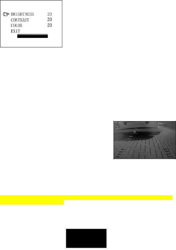
Press the OSD “Enter” button to enter the menu screen as shown below:
Repeat pressing the OSD “Enter” button to select
Brightness, contrast or colour of the picture. Press the OSD menu “+” button or
OSD menu “–“button to adjust settings within the control selected.
To exit the menu screen, select exit on the screen using the OSD “Enter” button and press either OSD menu “+” button or OSD menu “–“button to exit the menu screen.
MFB 1/Call button (MFB is abbreviation of Multi-
function Bluetooth)
Answer / Decline incoming calls Dialing outgoing calls
Voice dialing On / Off
Activate of searching mobile device (under Bluetooth sleep mode)
Dual color LED backlight. Red LED backlight twinkles when Bluetooth is not connected to mobile device. Blue LED backlight twinkles when Bluetooth is connected to mobile device
MFB 2/Up button
Go previous page of call log / address book
Press once (< 3 sec) for call log display, press twice for “previous page” call log display. Press continuous 3 sec, will activate phone book searching on connected mobile device and auto download
MFB 2/Down button
Go next page of call log / address book Press once (< 3 sec) for phone book display
Press continuous 3 sec, will active voice caller ID mode end with “one, two, three” voice warning. Press another 3 sec, will exit voice caller ID mode end with a “toot” warning tone.
Guideline button
The unit has the option to show distance-guidelines on the display. This helps you to visually see the distance between the objects behind your car. By pressing the guideline button, you can switch this option on and off.
Volume control
There is a dial for system speaker volume control in Bluetooth hand free mode.
Bluetooth hand free system operation
Refer the Bluetooth operation in your mobile device instruction to pair it with the Bluetooth hand free system.
NOTE: Subject to different version of your mobile device, the function and operation may be different to below description.
1.Upon power on for 3 sec, unit will start searching of rear view camera signal. If signal was found, Bluetooth system will turn off automatically
2.If rear view camera signal not found, unit will enter Bluetooth mode and search for
last connected mobile device. LCD will display as below and red LED twinkles:
SEARCHING…
9
3. When the unit is connected with the mobile device, the LCD will show the mobile device name, Blue LED of MFB 1 button twinkles. At this moment, if the mobile prompts to enter the online password, please use the mobile keys to enter”0000” and confirm. You can also set the mobile to connect automatically, for detailed operation, please refer to your mobile phone’s manual.
NOKIA 7230C
4.If no mobile device was found in 10 sec, Bluetooth will enter sleep mode, and red LED of MFB 1 will be off 2minutes later.
5.Under sleep mode, press MFB 1 button once will start searching the last connected mobile device again.
6.After unit paired up with mobile device, press MFB 1 button once will activate voice dialing function (subject to the function availability of mobile device) and the system will “beep” once.
7.Under connected mode, press MFB 2/ Up button once, will enter call log mode, press MFB 2/ Up or MFB 3/ Down button to select number and press MFB 1 button for calling. Press and hold MFB 2/ Up button for about 3 sec to quit call log mode.
8.Press MFB 3/ Down button once, will enter address book mode, press MFB 2/ Up or MFB 3/ Down button to select number and press MFB 1 button for calling. Press and hold MFB 3/ Down button for about 3 sec to quit address book mode.
OUTGOING CALL.. 87652321
9.Press MFB 2/ Up button and hold for 3 sec, will enter address book searching mode on the connected mobile device and download automatically (not including SIM card address book). The maximum capacity is 600 name / phone number. When the phone book is downloaded, press and hold MFB 2/ Up button to stop download, downloaded phone numbers will not be dropped.
|
|
TOTAL 13 |
|
END TOTAL 103 |
DOWNLOAD |
|
|
||
PHONEBOOK.. |
|
|
|
|
|
|
|
|
|
|
|
|
|
|
10.Press MFB 3/ Down button for 3 sec, enter voice caller ID mode. System will broadcast a message “one, two, three” to indicate the mode activation. Press again for 3 sec will exit voice caller ID mode and system will have a “toot” tone to indicate the mode deactivation.
11.When there is incoming call, press MFB 1 once will answer the phone. Press twice will decline the incoming call. Under talking states, press MFB 1 button once to hang up.
12.Press both MFB 2 & 3 buttons simultaneously for 5 sec, call log and downloaded phone book will be erased, LCD displays as below.
PB DELETED
10
TECHNICAL SPECIFICATIONS
Camera |
|
Operating Voltage |
12V DC |
Current consumption(include transmitter box |
<180mA |
Image sensor |
CMOS |
No. of pixel |
640x480 |
Resolution Horizontal |
>330 TVL |
Optical lens |
2,4mm / F2,1 |
|
|
Wireless transmitter |
|
Transmission frequency |
2468MHz |
RF transmission distance (open space) |
>80M |
|
|
LCD monitor |
|
Operation Voltage |
12V DC |
Standby Current |
<210mA |
Operation Current |
<450mA |
LCD display screen size |
3.5inch |
No. of pixel |
320x240 |
|
|
Bluetooth |
|
|
|
Bluetooth Standard |
Bluetooth2.1, class II |
|
|
Bluetooth transmission distance |
10m on open field |
|
|
Flash memory support phone number |
Up to 600 |
|
|
|
|
Operation temperature |
-10 to +45 degree Celsius |
ENVIRONMENTAL PROTECTION
Waste electrical products should not be disposed of with household waste. Please recycle where facilities exist. Check with your local authority or retailer for recycling advice.
WARRANTY
Pro-User warrants this product for a period of 2 years from the date of purchase to the original purchaser. Warranty is not transferable. Warranty covers defect against workmanship and materials only. To obtain warranty service, please return the unit to the place of purchase or authorized Pro-User dealer together with your proof of purchase. The warranty is void if the product has been damaged or not used as described in this manual. Warranty is void if a non-authorized repair has been performed. Pro-User makes no other warranty expressed or implied. Pro-User is only responsible for repair or replacement (at Pro-Users’ Discretion) of the defective product and is not responsible for any consequential damage or inconvenience caused by the defect.
11
EINLEITUNG
Der Artikel Pro-User APB120 gehört zur Familie der zukunftsweisenden Auto-Rückfahr- Kamera-Systeme der Firma Pro-User-International Ltd.
Das kabellose Pro User Innenspiegel-Rückfahrkamera-System mit integriertem Monitor im Innenspiegel ermöglicht es Ihnen bei ordnungsgemäßer Bedienung, hinter Ihr Auto, Ihren Anhänger oder Mini-Van zu sehen. Es wurden zahlreiche Maßnahmen bei der Qualitätskontrolle ergriffen, um Ihnen ein Top Produkt zu Ihrer Zufriedenheit zu liefern.
Bitte lesen Sie die Bedienungsanleitung sorgfältig durch und folgen Sie den Sicherheitshinweisen und der Montageanleitung.
WICHTIGE SICHERHEITSHINWEISE
Vor der Montage
Falls Sie sich nicht sicher fühlen, dieses System an die 12V Stromversorgung Ihres Fahrzeuges selbstständig zu montieren (bohren von Löchern, abnehmen von Verkleidungen etc.) nehmen Sie Kontakt zu Ihrem Autohaus oder zur Kfz-Werkstatt Ihres Vertrauens auf. Dort können Sie eine professionelle Montage des Systems in Auftrag geben.
Störung
Dieses Kamera-System kann, genau wie andere kabellosen Systeme, bestimmten Störungen unterliegen. Störungen können verursacht werden durch Handys, Bluetooth, Headsets, Navigationssysteme und anderen elektrischen Geräten.
Reparatur
Dieses Kamera-System darf nicht geöffnet werden! Bei jeglichem Versuch einer Reparatur erlischt die Garantie.
ZUBEHÖR
1. Innenspiegel mit integriertem Monitor 2. Kamera mit Befestigungsplatte
|
|
|
|
|
|
|
|
|
|
|
|
|
|
|
|
|
|
|
|
|
|
|
|
|
|
|
|
3. Sender |
4. InstallationsMaterial |
|
5. 12V Kabel für Monitor |
|||
|
|
|
|
|
Mit Zigarettenanzünder- |
|
|
|
|
|
|
adapter |
|
|
|
|
|
|||
|
|
|
|
|
|
|
|
|
|
|
|
|
|
|
|
|
|
|
|
|
|
|
|
|
|
|
|
6. Netzkabel für Sender 7. Klebebänder |
8. Netzkabel für Monitor |
||||
|
|
|
|
|
|
|
|
|
|
|
|
|
|
|
|
|
|
|
|
|
|
|
|
12
MONTAGE
Diese Bedienungsanleitung ist nicht für alle Fahrzeuge anzuwenden. Sie ist ein genereller Leitfaden für die meisten Fahrzeuge. Bei fahrzeugspezifischen Fragen wenden Sie sich bitte an Ihren Fahrzeughersteller.
Montage der Kamera
Es gibt verschiedene Möglichkeiten, die Kamera an der Rückseite Ihres Fahrzeuges zu befestigen. die Gebräuchlichste ist, die Kamera nahe dem Nummernschild zu befestigen. Sie können die mitgelieferte Montageplatte hinter dem Nummernschild befestigen. Auf diese Montageplatte können Sie nun die Kamera montieren.
Die Kamera ist vertikal schwenkbar, bitte stellen Sie diese nach den Gegebenheiten ein.
Bei manchen Fahrzeugen ist es leider nicht möglich, die Kamera nahe dem Nummernschild zu befestigen. Suchen Sie sich eine andere Stelle am Heck Ihres Autos und befestigen Sie die Kamera mit den mitgelieferten Schrauben und Muttern.
1.Nehmen Sie das Nummernschild aus der Halterung und lösen Sie danach die Schrauben des Nummernschildhalters und nehmen dieses ab.
2.Positionieren Sie die Befestigungsplatte mit der Kamera hinter dem Nummernschildhalter und befestigen Sie die Befestigungsplatte und den Nummernschildhalter am Fahrzeug.
13
 Loading...