


High Power
Lighting Module
INSTALLATION AND OPERATING INSTRUCTIONS
For Models:
XP4LS
XP1LS
10012 North Dale Mabry, Ste. 115
Tampa, FL 33618
Tel: (800) TECH-003
Fax: (813) 265-1011
Email: x10protec@x10pro.com
Web: www.X10PRO.com
Page 1

Congratulations! You have just purchased the best quality powerline carrier
lighting module available. X-10 PRO's Lighting Module is a high quality, X-10
compatible product that is a low cost alternative to hard-wired lighting systems.
This booklet covers all X-10 PRO models XP4LS and XP1LS.
CAUTION!!
READ AND UNDERSTAND THESE INSTRUCTIONS BEFORE INSTALLING DEVICE.
This device is intended for installation in accordance with the National Electric Code
and local regulations. It is recommended that a qualified electrician perform this
installation.
To reduce the risk of overheating and possible damage to other equipment, do not
install dimming versions to control a receptacle, a motor-operated appliance, a
fluorescent lighting fixture, or a transformer-supplied appliance. This product is for
indoor use only. Connect only copper or copper clad wire to this device.
Pour re'duire le risque d'augmenter la chaleur des diffe'rents equipments, ne pas
installer une piece de control, une machine `a moteur, une fixture fluorescente or un
transformateur.
Retain these instructions for future reference.
INSTALLATION
Installation Notes
a. Be sure that power to the supply circuit has been disconnected by removing fuse or
turning circuit breaker off. Installing the module with power on may expose you to
dangerous voltages and may damage the device.
Installation Procedures
1. Install a standard 4 gang box or RACO 953 box, pre-wire for power, loads, remote
switch, and transmitter controls.
2. Power should be a 20 circuit directly from a breaker 2x12ga wire and ground.
3. Load, remote switch, and transmitter circuits should each be connected via separate
sets of two 14ga wire with ground.
4. Using a voltage tester, identify and mark the “Hot” and the “Neutral” wires.
5. Identify and label each pair of load and control point wires.
6. If setting up an X-10 PRO lighting system enter the appropriate circuit labels and
addresses in the programming manual worksheets and on the module labels.
7. After all connections have been made, be certain all wire connectors are firmly
attached and there are no exposed wires (except the bare ground wire).
8. Place wires and insert into wall box and screw unit into place with supplied screws.
Four gang box uses four or eight 6x32x1/2 screws, Raco 953 box uses four
8x32x1/2 screws.
Page 2
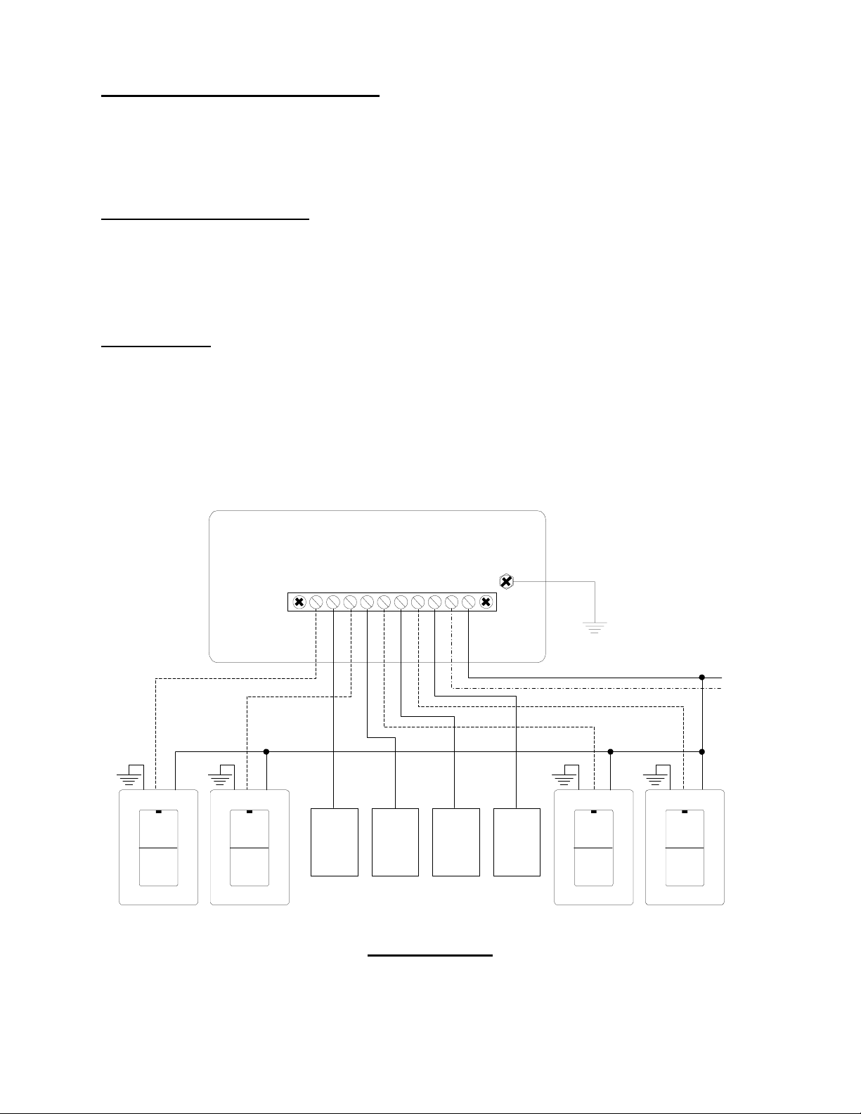
WIRING CONFIGURATION
The Lighting Module is wired directly to the lighting circuit and can be controlled by one
or more Remote switches producing three, four, or five-way circuits. Multiple-way
circuits make it possible for a group of switches to control the same set of lights. This
section will illustrate how to hook-up the connections.
Configuration Definitions:
SERVICE PANEL - Source of electricity providing the Line and Neutral
REMOTE SWITCH - One or more remote switches controlling the light circuit via the
Lighting Module control inputs.
Wiring Notes:
a. Remote switches require a Line Voltage input (Black) that is always hot. Do not
connect to the load (switched) circuit.
b. The gray wire on the Remote Switch only serves to light the red LED, which
provides as a night light and power indicator. It does not indicate the state of t he
load. This wire can be tied to neutral or earth ground.
Light i ng Mo du l e
CNTRL1
LOAD1
CNTRL2
LOAD2
CNTRL3
LOAD3
CNTRL4
LOAD4
WHITE
LINE
Ground
(Yellow)
(Gray)
Gnd* Gnd* Gnd* Gnd*
Remote 1 Remote 2 Remote 3 Remote 4
(Black)
Light
Fixture 1
* Can be connected to Nuetr al
Light
Fixture 2
Light
Fixture 3
Light
Fixture 4
Line
Neutral
Remote
Switches
(Optional)
Wiring Diagram
Page 3
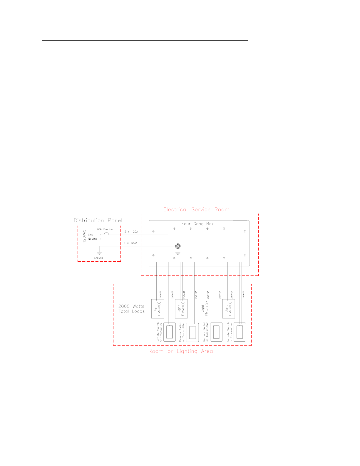
PRE-WIRING for X-10 PRO's Lighting Modules
The following is a guide to a “home-run” type wiring configuration that ensures a
versatile and reliable system. This configuration costs slightly more in materials and
labor to run the 14 gage home-runs for each load and control point. This expense,
however, is more than offset by the increase in system reliability having all associated
lighting and control points electrically “close” or in the same vicinity. The ease of setup
and programming are worth it for simple and inexpensive installation.
The "home-run" wiring scheme is very different than conventional wiring methods. The
conventional way typically taps off or "daisy chains" as many fixture/switch sets as
possible off of each 20A supply circuit. This method is the least expensive method in
getting the required control points/fixtures connected throughout the house but doesn't
allow for other methods of control.
The "home-run" method proposed in this pre-wiring guide cost somewhat more, but is
so versatile that anything from complex scene systems to simple switch/fixture
arrangements can be easily implemented.
Single Room Wiring
A typical wiring diagram for one room might be as shown in Figure 1.
Page 4
 Loading...