

Page 1
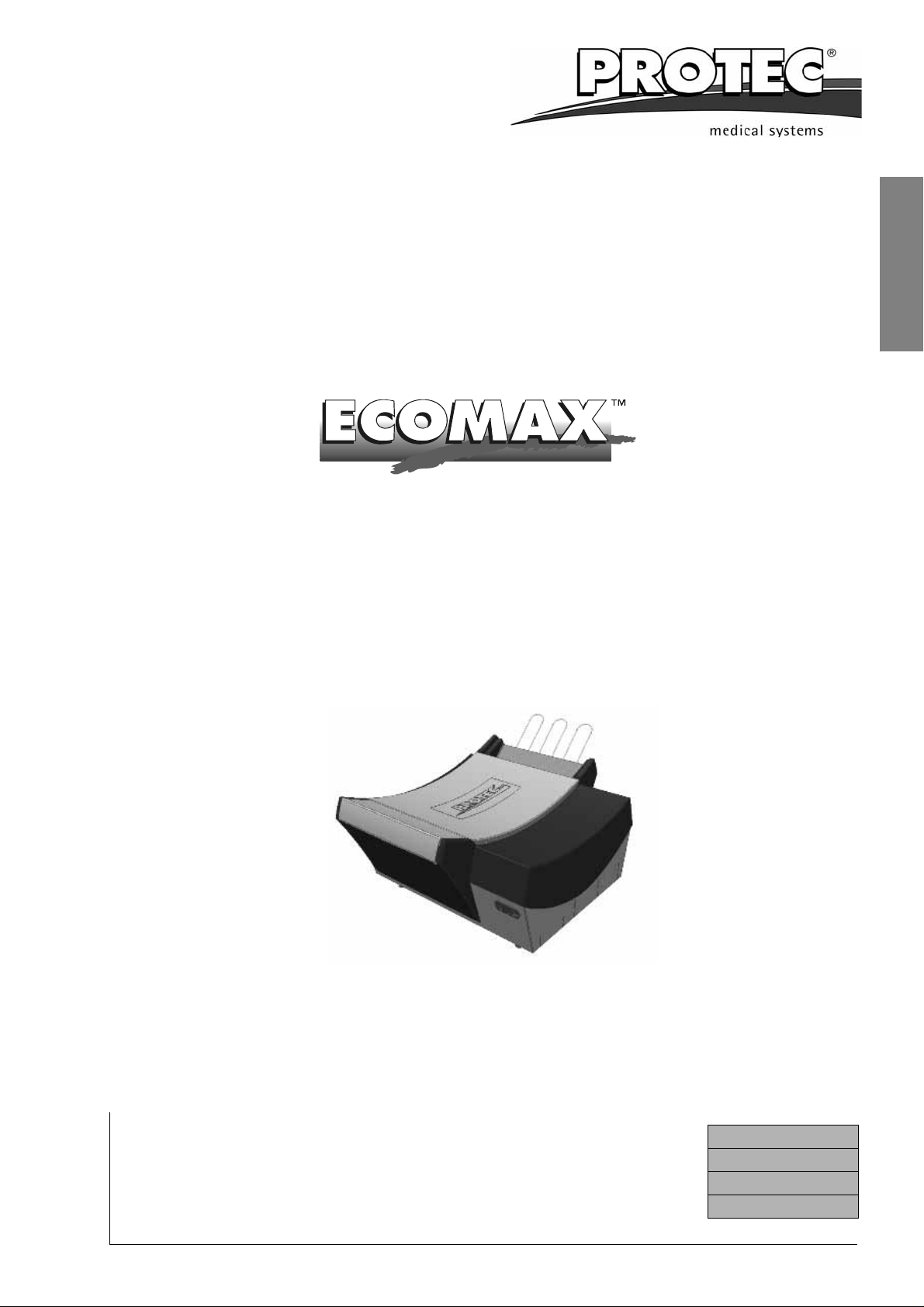
Film Processor
Operation Manual
English
PROTEC GmbH & Co. KG
In den Dorfwiesen 14, D-71720 Oberstenfeld, Germany
Telephone: +49-7062-9255-0 e-mail: [email protected]
Machine No.:
Type:
Installation Date:
Status: 08-2009/1.3
Subject to change
Page 2
EU-Declaration of Conformity
EU-Declaration of Conformity
PROTEC® declares, that the product
Description:
Machine type:
Model no.
conforms to the following harmonized standards:
ECOMAX
X-Ray-Film Processor
1 186-x-0000
x is a number between 1 and 9
TM
Safety:
EMC:
according to the regulations of:
IEC 61010-1:2001; DIN 1988 T4:12/1988; UL 3101-1; CSA 22.2-1010-1
EN 61326:1997 + A1:1998; EN 61000-3-2:1995 + A1/A2:1998 + A14:2000;
EN 61000-3-3:1995
• the Medical Device Directive 93/42/EEC “Class 1”,
• the Low Voltage Directive 73/23/EEC and the
• EMC Directive 89/336/EG
Supplementary guidelines:
• DIMDI: DE / 0000042967
• WEEE: DE 55471807
PROTEC GmbH & Co. KG, Lichtenberger Strasse 35, D-71720 Oberstenfeld, Germany
Place and date of issue:
Oberstenfeld, 02. July 2007 Jochen Krupp (Technical Manager Analogue Systems)
2 ECOMAX
TM
Page 3

Table of Contents
Introduction.......................................................................................................... 3
Intended Use.........................................................................................................4
Technical Specifications..................................................................................... 6
Safety Instructions............................................................................................... 7
Installation............................................................................................................8
Initial Operation.................................................................................................. 11
Operation
Short Overview and Front Panel Pad..........................................................12
Stand-by mode................................................. .. .........................................13
Switching on the machine............................................................................14
Display “Infeeding film”................................................................................ 14
Anti-Chrystalisation Function / Anti-Oxidisation Function............................ 14
Automatic replenishment............................................................................. 15
Care
Daily Care.................................................................................................... 16
Weekly Care................................................................................................ 16
Thorough Cleaning......................................................................................17
Maintenance / Disposal ..................................................................................... 18
Problems and Solutions
Advice on Film Defects................................................................................21
Advice on Machine Errors ...........................................................................22
Accessories........................................................................................................ 23
Service Manual as appendix, see page page 25
English
Copyright
© 2007 by PROTEC
tions set forth by copyright law, needs to be authorised in writing by PROTEC®.
Information on Liability
This manual has been checked for correctness. The instructions and specifications
were correct at the time it was published. Future models may have modificati ons
without prior notice.
PROTEC® does not take responsibility for damage caused directly or indirectly by
error, omission or non-conformity of the manual.
®
. All rights reserved. Any reproduction that violates the limita-
Introduction
The ECOMAXTM processor is a compact, automatic table-top processor. Due to the
precision roller transport system, sheet films can be processed. The film materials
are developed, fixed, rinsed and dried. The ECOMAX
tomatic film-registration and a Stand-by mode. The developing solutions a re temperature-regulated, circulated and automatically replenished.
These Operating Instructions contain important instructions for installation, o peration and servicing of the machine. Please read the provided information carefully to
ensure reliable and satisfactory operation of your ECOMAX
TM
has been fitted with an au-
TM
.
ECOMAX
TM
3
Page 4

Intended Use
Intended Use
The X-ray film processor ECOMAXTM is intended exclusively for the p urpose describe in the introduction above.
X-ray film processorss (MDD class I) are employed in “medical” applications (medical products directive) and “non-medical” applications (electri cal appliances and
EMC directives).
Intended use includes observing the operating instructions, the installation instructions and adherence to the safety notes.
®
Any application differing from intended use voids the guarantee by PROTEC
The owner of the machine will be liable for damages resulting from unintended use
or faulty application.
Intended use includes adherence to all statutory re gulations concerning occupa-
tional safety and radiation protection applicable at the operating site.
.
4 ECOMAX
TM
Page 5

English
ECOMAX
TM
5
Page 6
Technical Specifications
Technical Specifications
Film transport:
Film formats:
Processing capactiy:
Process time:
Linear speed:
Developer time:
Tank capacities:
Circulation system:
Replenishment:
Developer temperature:
Fixer temperature:
Continuous roller transport system
In general: sheet films up to max. 35.8 cm
(14.1’’) width;
Smallest film format 10x10 cm (4x4 ’’).
74 films 24x30 cm (10x12 “) per hour (standard
model, feed film crosswise)
Standard 105 s
Standard 37 cm/min. (14.5 in/min)
Standard 29 s
Developer, fixer 2.3 litres each (0.51 gal) and
water tank 2.1 litres (0.46 gal)
Developer and fixer are continiuously circulated by
a circulation pump
Automatic replenishment by film detection, in relation to film length
Ex works set to 32 °C (89.6 °F)
In exceptional cases can be set by a technician
Adjusted to developer temperature by heat
exchanger.
Water connection:
Water consumption:
Drain capacity:
Noise level:
Heat emission:
Environmental cond itions:
Pollution degree:
System protection:
Permissible water pressure 2 - 10 bar (29 - 145
psi), permissible water temperature 5 - 30 °C (41 86 °F).
1.0 litres per minute (0.26 gal/min) when processing.
7 litres per minute (1.85 gal/min).
Less than 60 dB(A).
Operation: 0.1 kJ/s,
Development: 1.1 kJ/s
1) Temperature 18 - 40 °C (51.6 - 104 °F), ventilated room, room temperature should be lower
than set bath temperature.
2) Relative humidity lower than 80% up to 31 °C
(80 °F), linearly decreasing to 50% at 40°C
(104°F)
3) Height above sea level less than 2000 m (6666
ft.)
4) Indoor use
2
IP 20
6 ECOMAX
TM
Page 7
Technical Specifications
Electrical connections:
Power consumption:
Weight (unit):
Dimensions (LxWxH):
Floor space required:
Safety Instructions
Electrical specifications are indicated on the model
nameplate.
Type 1186-1-0000: 230 V±10%, 5.8 A, 50 Hz.
Type 1186-2-0000: 230 V±10%, 5.8 A, 60 Hz.
unit conforms to IEC 1010 (EN 61010, VDE 0411)
overvoltate category II
Type 1186-3-0000: 110 / 120 V~ ±10%, 12 A, 60
Hz, Type 1186-6-0000 110 / 120 V~ ±10%, 12 A,
50 Hz unit conforms to UL 3101 and CSA 22.21010
overvoltage category II
Operation: 0.12 kWh
Development: 0.9 kWh
Empty 26.5kg (58.3 lbs)
Filled 34 kg (74.8 lbs)
88x66x42 cm (34.7x26.4x17.0 ’’)
0.58 m2 (6.2 sqft)
English
To ensure the safe operation of this processor, installation and use should always
conform to the instructions contained in this manual.
The developer and fixer chemicals used in the processor should be handled
according to the manufacturers instructions. In general: Undiluted chemica ls are
caustic. For this reason, chemicals should be handled very carefully. Avoid contact with skin, always wear protective clothing, gloves and glasses when handling
the chemicals - for example, when mixing and refilling. Also when taking the
racks out for cleaning or servicing. If chemicals have come in your eyes, rinse the
eyes immediately with cold, running water for approximately 15 minutes and contact a medical doctor afterwards. Inhalation of chemicals can be dangerous to
your health and should be avoided. For this reason, always ensure that the room
in which the processor is installed is adequately ventilated.
Environmental regulations regarding the storage and disposal of waste chemicals should be obtained from the local water authorities and complied with.
Before opening the unit, switch off the unit and unplug it from the electrical
socket. Service and repairs must be performed by trained service technicians
only. Use only manufacturer´s replacement parts.
ECOMAX
TM
7
Page 8
Installation
Installation
1. Requirements for installation
a. Fresh water connection: Shut-off tap, thread with 3/4" outside diameter
(washing machine connection), Water pressure 2 - 10 bar (29 - 145 psi).
b. Drainage connection: Plastic tube - inner diameter 50 mm (2”) or larger. A
ventilated syphon which serves as odour preventor should be included in the
planning. The drainage tubes should be installed with a decline of minimum 5
%.
Local Water Authorities regulations should be complied with.
c. Electrical connection: Fused wall socket with earth connection according to
electrical data (see technical specifications, page 7). It is also required to
install an earth-leakage switch (with 25 A / 30 mA nominal error current).
Electrical connections should be carried out according to regulations by an electrician.
2. Transport
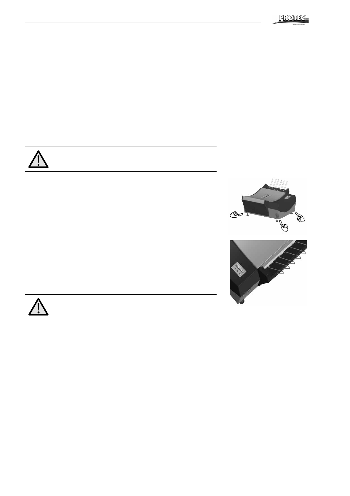
Due to the weight and dimensions of the film processor ECOMAXTM should always
be carried by two persons. To do so, hold the machine on the sides of the bottom
pan (see figure). While putting the machine down, watch the position of the levelling
feet to prevent damaging these.
3. Set-Up
Unpack the Processor. Remove light protection cover and machine cover, remove
roller racks, begin with the developer roller rack (red).
Remove the brackets for film output from the packaging and press them into the
openings on the rear of the film output until they snap into place. Be sure the long
side of the bracket points inward and touches the film output on top (see figure).
Table-top installation
In the event that the processor is to be installed on a work top or table, the four adjustable feet should be screwed on.
Attention!
Machine should not be installed on table-top without adjustable feet. The ventilation openings under the machine must not
be blocked, as this can cause overheating.
Unit with Worktable
If the unit is set up on a worktable (optional accessory), the unit should be screwed
to the worktable. Mount the unit as outlined in the manual (included with the worktable).
Finally the processor needs to be levelled:
Place spirit level across the walls of the baths and adj ust the le ve lli ng feet accordingly (on the unit itself or on the worktable). Reinstall the roller racks in the unit and
lock them; begin with the dryer roller rack.
8 ECOMAX
TM
Page 9
Installation
4. Connecting the processor
English
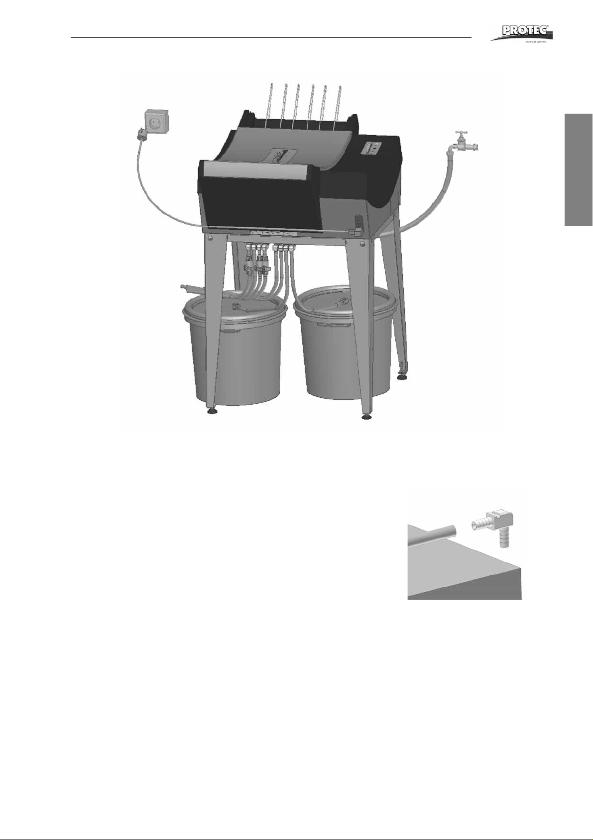
Water connection: Connect the water hose which comes out from the processor’s
back to the fresh water supply.
All other hoses (see diagram page 10): First cut off the pre-installed hoses at the
film processor so that the angle stubs protrude somewhat beyond the edge of the
table (see figure). Connect the enclosed hoses at the front of the machine according to the colour system. Put hose clip (enclosed in accessory bag) over hose end,
before attaching to connection. Warm up hose end (with hot water o r lighter) and
push onto the respective connection. Finally push clip over hose and connection.
Cut hoses to required length. Then integrate the stop cocks into the three drainage
hoses in such a position, that they are easy to reach.
Using the hose clips, connect the suction pipes to the ends of the hoses for the replenishment tanks. Feed the suction pipes through the cover opening into the respective replenishment tanks and snap them in to place.
The overflow and drainage hoses from the developer an d fixer should be guided
into their respective collecting containers.
The overflow and the drainage of the water can either be guided into the drainage
syphon or into respective collection containers.
ECOMAX
TM
9
Page 10
Installation
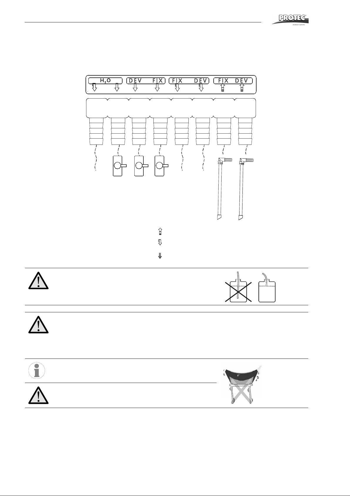
Pay attention to the correct colour connections:
Developer: red;
Fixer: blue;
Water: clear
Replenishment
Overflow
Outlet
Hose Connections
Danger of Overflow!
Use the included cable ties (accessory bag) to secure the hos-
es. Fix all hose ends which lead into the s yphon or c ollecting
container, so that they do not drop into the liquid.
Very important:
The hose piping should be straight (without the hoses going
up and down) with a constant decline. The hoses should be as
short as possible and without bends and kinks. This is very
important for the water overflow hose. Bad water overflow piping work may cause the machine to overflow!
Inform yourself of the local water board regulations regarding
drainage. These regulations may differ from information in
this manual, but they should be complied with.
If the machine is installed table-top, ensure that the table is
stable enough and does not wobble.
10 ECOMAX
TM
Page 11
Initial Operation
Initial Operation
1. Test run
Important!
Processor should not be run dry!
a. Close the three drainage stop cocks and fill the tanks and replenishment con-
tainers with water. Open water inflow tap. Connect electrical socket and
switch the machine on. Water now flows into water tank. The circulation pump
activates, however the hosing of the machine must be ventilated.
b. Ventilation of the replenishment pump:
Switch the machine off again. Open the stop cocks of the developer and fixer
for five seconds and switch machine on again. Repeat this procedure until no
more air bubbles are visible in the developer and fixer baths and until the circulation pump runs quietly.
c. Ventilation of the circulation pump:
If air is in the circulation pump, a loud running noise can be heard. Switch the
machine off again. Open the stop cocks of the developer and fixer for five seconds and switch machine on again. Repeat this procedure until no more air
bubbles are visible in the developer and fixer baths and until the circulation
pump runs quietly.
d. Check all hose connections for leakage. Switch machine off and drain water
out.
English
2. Filling the Processor with Chemicals
Prepare chemicals inside the replenishment containers according to manufacturers
instructions.
Filling the processor manually
By using a suitable container, pour chemicals into the respective tanks. First the fixer and then the developer. Caution: when filling, be sure that chemicals do no
splash from one bath into another. When fixer solution is mixed with developer solution, the developer chemical is destroyed.
Snap each suction pipe into the respective cover of it’s replenishment container and
close it carefully. Place containers under processor.
Important!
The machine should not be switched on in dry condition (no
water/chemicals filled in), since the circulation pumps would
otherwise run dry and be damaged.
Automatic filling of the unit / manual replenishment:
a. The chemicals containers need to be filled manually with at least 0.5 litres of
fresh chemicals, to ensure the pumps will not run dry.
b. Switch the machine off.
c. Keep the film detection switch pressed when switching the machine on again.
d. Release the film detection switch. The replenishment pump will now run for 9
minutes or until the machine is switched off again. This function can also be
used for manual replenishment.
ECOMAX
Warning, hot surface!
TM
11
Page 12
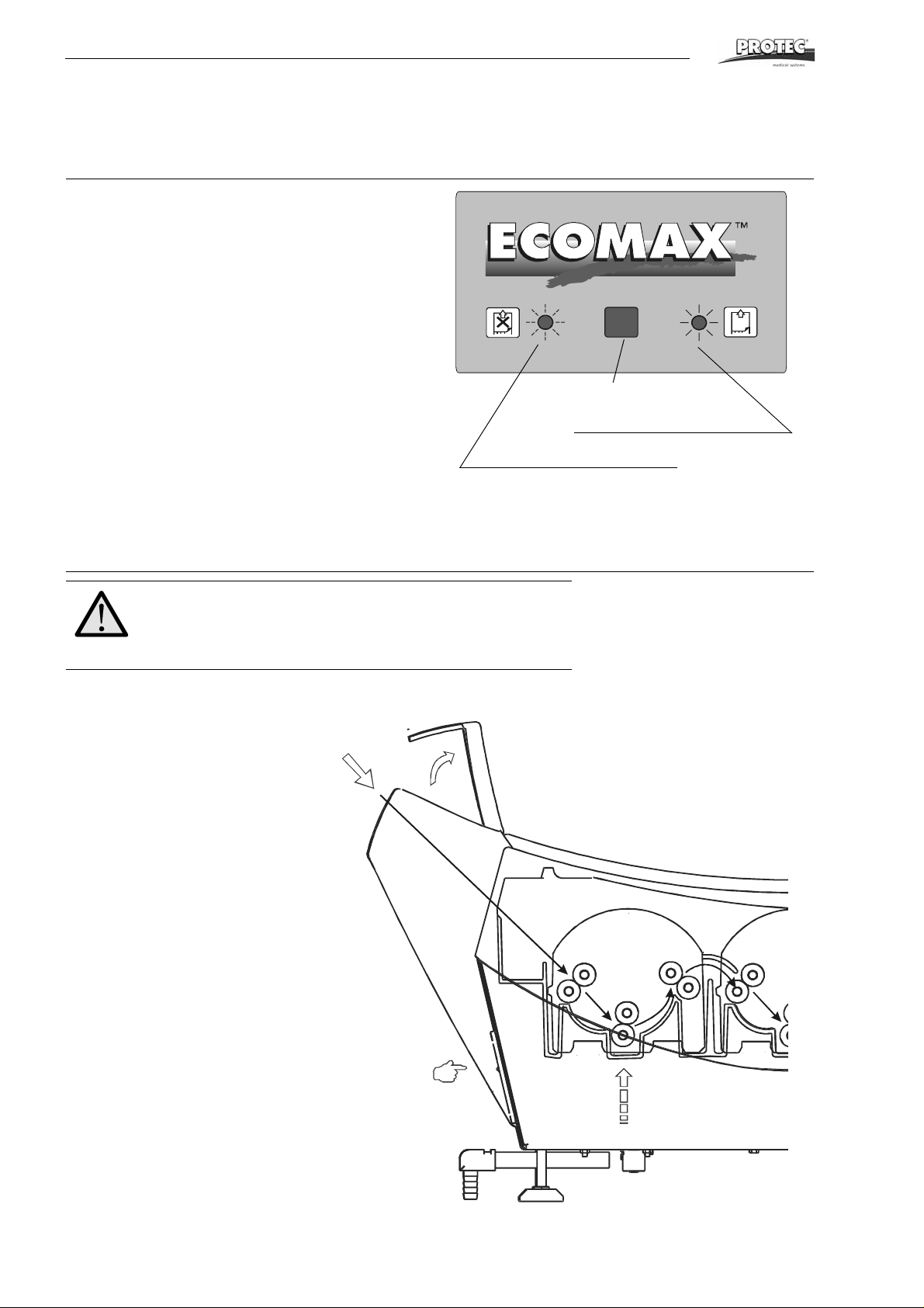
Operation
LED
Symbol for film feed released
Symbol for film feed locked
Operation
Short Overview and Front Panel Pad
Functions
• Feeding film
Before feeding the next film wait until the LED stops
flashing, but is continuously on. An acoustic signal
additionally indicates that the next film can be
inserted.
• Power (ready to operate)
The LED is on as long as the unit is on.
• Warming up
During warm-up the LED flashes; bef ore fe ed i ng th e
next film wait until the LED stops flashing, but is continuously on. The end of the warm-up phase is indicated by an acoustic signal. If you try to insert a film
during warm-up, an interval sound will occur permanently.
• Bath heating failure
If the developer temperature is not reached within 30
minutes, the LED starts flashing rapidly and an interval sound occurs permanently.
Important!
Safety function stops film transportation when cover is re-
moved. Therefore keep cover placed on the machine when
processing films.
12 ECOMAX
TM
Page 13
Operation
Do not place any
object on the processor.
Before use...
1. Close water-drainage stop cock.
2. Open water tap.
3. Switch processor on.
4. Check liquid level in replenishment and drainage collecting containers.
5. Wait until the developer temperature is reached. The LED stops flashing when
the heat-up phase is completed.
6. Run cleaning films through processor.
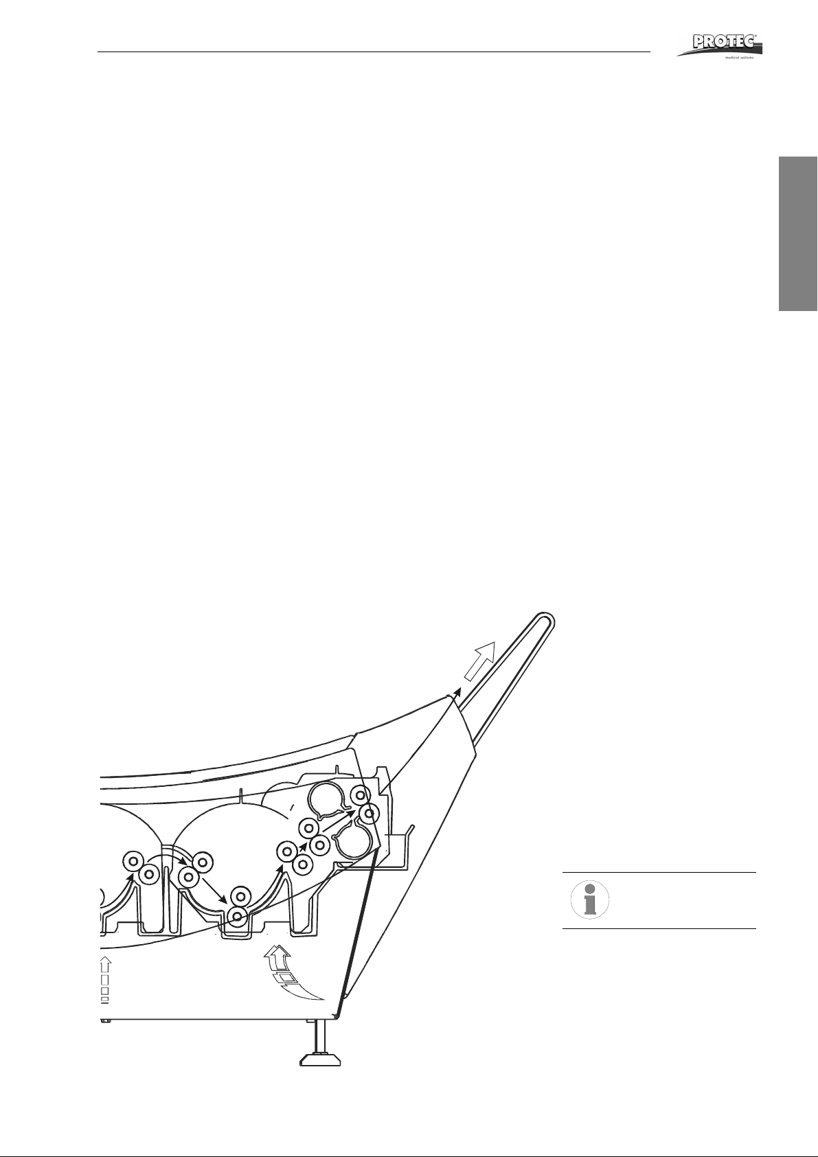
Working procedure
7. Processing films:
Open light protection cover. Important: Put film first on left side of infeed tray
and then feed in. During processing films please watch the “Feeding film”
LED. If it flashes, wait until it stops before feeding the next film; the LED must
be continuously on and an acoustic signal must indicate that it is okay to feed
a film.
After work...
8. Switch the unit off.
9. Close water tap.
10. Open water-drainage stop cock and drain water out of the machine.
Stand-by mode
When no film is being processed, the machine switches to Stand-by. The chemicals
remain at a constant temperature. The film feed, the replenishment pumps and the
water supply are switched on briefly at regular intervals, to prevent crystallisation of
chemimals on the transport rollers and oxidisation of the chemicals. A film can be
inserted at any time.
.
English
ECOMAX
TM
13
Page 14

Operation
Switching on the machine
The processor is switched on at the main switch (front right). The developer bath
will be heated up. The LED flashes during the warm-up phase and no X-ray film
must be inserted into the machine during this time. When the ma chine is ready, a
acoustic signal is heard and the LED is on continuously.
Display “Infeeding film”
If films are fed into the processor without gap one after another, then this may cause
a film jam. The “Feeding film” LED flashes as long as a film is fed. Once the film has
been fed completely the LED is on continusouly. Additionally an acoustic signal indicates that the next film can be inserted.
Both chemicals pumps - for fixer and developer - are driven in
parallel by only one motor and therefore always run simultaneously. The regeneration volumes for developer and fixer thus
are identical.
Anti-crystalisation function
During the stand-by mode, the film transport, the dryer ventilation, the dryer heating
and the water inflow are activated every 20 minutes for a period of 20 seconds. This
prevents the build-up of crystals on the rollers.
Anti-Oxidisation Function
Also during the stand-by, the developer chemicals are subject to change which
causes their deterioration. By means of the time replenishment, a replenishment cycle is activated after 60 minutes without replenishment. The pump runs for
10 seconds. With this function, the qu ality of the developer chemicals are maintained even when standing idle for long periods.
14 ECOMAX
TM
Page 15

Operation
Automatic replenishment
Depending on the processed amount of films the chemical s are replenished automatically. This is done by pumping chemi cals from the replenishment containers.
The surface area of the film processed is calcula ted on the basis of the film detection switch at the film feed. For every 40 seconds that the film detection switch is
activated, a regeneration cycle of 13 seconds is started; thus a volume of fresh
chemicals is introduced that is adequate for the film length processed. This corresponds to a regeneration rate of 600 ml pro m
chart below shows the replenishment rate in ml per m2 film surface in relation to
film width and setting of the pump.
REPLENISHMENT RATE
replenishment pump*
100 % (85 %)** 75 % (62 %)
Setting of the replenishment time
2
of film at a film width of 35 cm. The
Setting of the
by the controller
English
Film width 13 s 10 s 13 s 10 s
35 cm
24 cm
18 cm
600 ml/m
870 ml/m
1 150 ml/m
2
2
2
470 ml/m
690 ml/m
920 ml/m
2
2
2
450 ml/m
650 ml/m
875 ml/m
2
2
2
350 ml/m
520 ml/m
690 ml/m
*Setting at 50 Hz current resp. settings at 60 Hz current are in brackets
**Standard setting
2
2
2
ECOMAX
TM
15
Page 16
Care
Care
Daily Care
Before use...
• Remove dirt and dust from film-infeed with soft cloth.
• Run 2 - 3 cleaner films through the processor to remove all accumulated dirt
and dust from the rollers.
• Check the liquid level in the replenishment containers and if necessary refill.
• Leave light protection cover open when no film is in the processor. This avoids
condensation on infeed.
After use...
• When work has been completed at the end of the day, drain water out of the
machine. This avoids the growth of algae in the water.
Attention: Do not allow liquids to enter the interior of the unit.
Liquids may cause damage to the processor.
Weekly Care
The developer chemicals cause residue buildup in the machine. This residue has a
negative effect on the developing process of the film material. For this reason the
processor should be regularly cleaned. Proceed as follows:
1. Switch the machine off, lift of light protection cover and cover.
2. Loosen the securing latches of the roller racks (red, blue and beige) on the
drive shaft.
3. Remove the roller-racks. First remove the developer rack (red). Then remove
the fixer (blue) and dryer (black) racks one after the other. The roller racks of
the developer and the water bath can be removed and inserted easier if you
tilt them a little.
4. Rinse all racks thoroughly under warm running water and then leave to drain
off. Use a soft sponge (do not use scouring-pad, as this would scratch the rollers!) and remove the pollution from the rollers.
5. Replace the racks: Red = Developer, Blue = Fixer. Black = rinsing/dryer.
Begin with the dryer, proceed with the fixer and last insert the developer rack.
Ensure that the racks are properly placed and do not forget to lock the drive
shafts.
6. Re-install machine cover and light protection cover; be sure these are properly placed; check that the machine cover actuates the cover switch.
7. Clean processor outer shell with damp cloth. Do not use aggressive cleaners
or solvents.
Important notes:
When removing the rinsing / drying roller-rack, ensure that no
water gets into the film dryer air channel.
For removal, the rinsing / drying roller-rack must first be
turned toward the film output, then it can be lifted out.
16 ECOMAX
TM
Page 17
Care
Thorough Cleaning
Every three months (maybe earlier) a thorough cleaning is necessary, depending
on the quantity of films processed. Tank cleaners are available for developer and
water baths. The fixer bath is cleaned with water. When preparing chemical tank
cleaners, follow manufacturer's instructions explicitly.
How to proceed:
1. Switch the machine off and empty all tanks by opening the stop cocks.
2. Remove light protection cover and machine cover and wait until the tanks are
drained completely; then close the stop cocks again. Now fill the fixer-tank
with water. Prepare cleaner solutions for developer and water baths and fill
into respective tanks.
3. Remove suction pipes from the replenishment containers and place them in a
water filled bucket. Attention: Do not add chemical cleaners here!
4. Install the machine cover and switch the machine on.
5. Start film transportation and keep it running for 10 to 20minutes. After the
heat-up phase, place a film in the feed so that it activates the film switch but
will not be pulled into the processor. During the operation with water, the
installed roller racks will be cleaned.
6. Important: After completion of tank cleaning, the tank should be rinsed thoroughly with clean water. To do this, fill the machine with fresh water twice and
each time, let the machine run for a 10 minute period. Empty the tanks and reclose the stop cocks.
7. Remove the service cover. Take out the roller-racks and rinse them thoroughly with running water. Remove remaining dirt from the rollers by using a
sponge and clean thoroughly. Doing this, the rollers can be turned by turning
the drive shaft. Reinstall the roller-racks in the machine.
8. Refill the tanks with respective chemicals. Replace the suction pipes into the
replenishment containers. In certain circumstances the circulation system
must be ventilated: see page11, item 1c.
9. For quality check, process test films.
Before you go on holiday...
or if your processor will not be in use for longer than two weeks, all the chemicals
have to be drained from the tanks. In case you don't want to do a complete tank
cleaning at once, then fill the tanks after emptying, with water.
English
ECOMAX
Attention: Do not use alcohol containing solvents to clean the
machine!
The colour changes in the baths is normal; it is caused by the
properties of the chemicals!
TM
17
Page 18
Maintenance / Disposal
Maintenance / Disposal
Maintenance Protocol
Installation
Name: Machine type: Serial number:
Technician: Training: by:
Telephone: Date: Guarantee until:
Parameters Set
Developer temp.: Dryer temp.: Cycle time:
Dev. reg. volume: Dev. reg. volume: Anti-oxidation:
Developer: Fixer: Film type:
Changed by: Date:
Developer temp.: Dryer temp.: Cycle time:
Dev. reg. volume: Dev. reg. volume: Anti-oxidation:
Developer: Fixer: Film type:
Changed by: Date:
Developer temp.: Dryer temp.: Cycle time:
Dev. reg. volume: Dev. reg. volume: Anti-oxidation:
Developer: Fixer: Film type:
Changed by: Date:
Maintenance work performed (see page 19)
Maintenance work
performed
Date: Date: Date: Date: Date:
Name: Name: Name: Name: Name:
next maintenance: next maintenance: next maintenance: next maintenance: next maintenance:
Maintenance work
performed
Date: Date: Date: Date: Date:
Name: Name: Name: Name: Name:
next maintenance: next maintenance: next maintenance: next maintenance: next maintenance:
Maintenance work
performed
Date: Date: Date: Date: Date:
Name: Name: Name: Name: Name:
next maintenance: next maintenance: next maintenance: next maintenance: next maintenance:
Maintenance work
performed
Maintenance work
performed
Maintenance work
performed
Maintenance work
performed
Maintenance work
performed
Maintenance work
performed
Maintenance work
performed
Maintenance work
performed
Maintenance work
performed
Maintenance work
performed
Maintenance work
performed
Maintenance work
performed
18 ECOMAX
TM
Page 19
Maintenance / Disposal
Attention:
Never start the machine up unless it is filled with liquid!
Recommended Maintenance Work:
1. Functional check
film intake / film transport / replenishment / bath heating / dryer heating / water supply
2. Cleaning
2.1. Switch off machine, remove cover
2.2. Empty all three tanks
2.3. Close drain cocks and fill tanks with water
2.4. Install cover, switch machine on
2.5. Fill two additional containers with water, place the suction pipes in these containers and activate the film intake
until the replenishing system is filled with water
2.6. Switch machine on for a few minutes
2.7. Switch machine off
2.8. Empty all tanks
2.9. Prepare tank cleaning agent for developer and water tank according to manufacturer´s instructions
English
Attention:
Do not use chlorine containing cleaning agents!
2.10. Fill developer and water tank with tank cleaning agent (do not
2.11. Fill fixer tank with water
2.12. Place suction pipes into empty tanks
2.13. Install cover, switch machine on
2.14. Wait until the operating temperature is reached, (observe information concerning temperature, time, cleaning
procedure contained in the datasheet of the tank cleaning agent)
2.15. Activate the transport (activate film intake)
2.16. After approx. 15 minutes (observe information concerning temperature, time, cleaning procedure contained in
the datasheet of the tank cleaning agent) switch film transport off
2.17. Remove cover, neutralise developer tank (observe information concerning temperature, time, cleaning proce-
dure contained in the datasheet of the tank cleaning agent)
2.18. Switch machine off
2.19. Empty all three tanks
2.20. Fill machine with water and switch it on
2.21. Put suction pipes into vessels with water
2.22. Activate the film intake until the replenishing system is filled with water
2.23. Check all pumps for tightness
2.24. Switch machine off
2.25. Drain tanks
2.26. Fill tanks 3/4 with water
2.27. Switch machine on
2.28. Activate film transport for a few minutes
2.29. Switch machine off and drain all three tanks
2.30. Repeat item 2.20 to 2.29 if required (observe information e. g. regarding temperature, time and cleaning proce-
dure outlined in tank cleaner datasheet)
use the replenishment pumps to do so)
ECOMAX
TM
19
Page 20
Maintenance / Disposal
2.31. Remove roller racks from the machine and remove dirt under flowing water using a soft rag or sponge
2.32. Remove risidual dirt particles from the tanks
2.33. Clean all toothed gear wheels, axles, bearings and rollers, check them for damage (replace if required)
2.34. Clean inlet plate using a soft rag
2.35. Align roller racks and re-insert them in machine
2.36. Fill machine with chemicals
2.37. Switch machine on
2.38. Feed cleaning film (approx. 4 pieces)
2.39. Check function as described under item 1.
2.40. Perform sensitometric test
Be sure to dipose properly of used machines.
Used machine contain valueable materials that should be recycled
and turned over for proper treatment. Please be sure to turn used
machines over to approved recycling centers.
20 ECOMAX
TM
Page 21
Problems and Solutions
Problems and Solutions
Advice on Film Defects
Your processor has been constructed for long term use. Howe ver, if irregularities
occur, you will find help to locate the problem below. Please check the listed points,
before calling your service-technician.
Films do not have enough density
• Bath temperature is too low.
• Developing time too short.
• Exposure time is too short.
• Replenishment rate of developer too low.
• Developer chemicals are exhausted or too strong diluted: Renew.
• Fixer solution has been mixed into developer: Renew. Clean and rinse bath
well before refilling.
• Circulation is broken down.
Too high a density
• Bath temperature too high.
• Developing time too long.
• Exposure time is too long.
• Replenishment rate of developer too high.
• Developer chemicals are too high diluted : Renew.
• After renewing chemicals: Starter is missing.
• Circulation is broken down.
English
Films will not dry
• If warm air comes out of the air channel in the dryer, chemicals and film type
should be checked.
• Fixer solution is exhausted or diluted.
Film has a yellow-green surface
• Not fixed correctly. Check the film type and fixer chemistry.
• Fixer solution is exhausted or diluted. Replenishmen t rate of fixer is too low.
Scratches, pressure marks, dirt on film
• Prior to processing films, run cleaner films through the processor.
• Pressure marks caused by careless handling, finger nails etc.
• Rollers are polluted. Clean tanks and roller racks.
Cloudy film
• Level in developer is too low.
• First guide bar of fixer rack is dirty (condensate or crystals). Clean rollerracks.
• Developer is old or circulation not working.
• Try processing films by infeeding them with emulsion side up.
ECOMAX
TM
21
Page 22
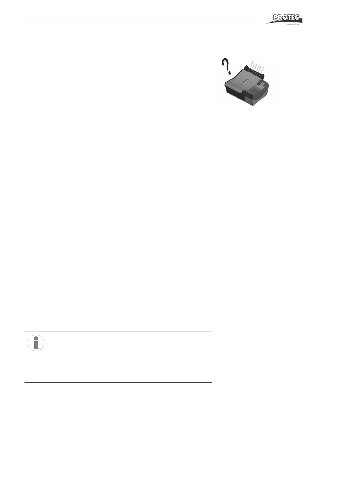
Problems and Solutions
Advice on Machine Errors
Unit does not switch on
• Ensure that electrical plug is firmly inserted into socket.
• Ensure that electrical socket has power supply by testing with an appliance
(e.g. tablelight).
Film is not drawn in
• Place cover correctly on machine, ensuring that the cover switch on the right
rear side is activated.
Machine does not start automatically
• Film switch left side at the infeed has not been pressed down. Feed in the film
to activate the switch.
Developer temperature too low
• Developer heating is defective
• Capillary tube controller is defective or its adjustment is faulty - call service
technician
Replenishment pump does not pump
• Check whether the replenishment containers are full and that the end of the
suction pipe is positioned under the liquid level.
• Check whether there is air in the replenishment hoses. If this is the case,
check the hose connections.
Rinsing water does not flow
• Open water inflow tap.
• The water pressure in the water supply system is too low: Minimum pressure
2bar (29psi).
Water tank overflows
• Water drainage hose (overflow) is bent. The hose end should be positioned
above the drainage level in the syphon (see diagram on page 10).
• Check water drain opening in the tank and the hose for blockage and resi dues. The drainage hoses should have a constant fall.
The film does not transport correctly
• Film is fed in and gets caught in the machine: Check the positioning of the
racks in the machine and make sure that the latches on the drive sha ft are
closed.
Important notes:
Ensure correct seating of roller racks; keep the lock closed at
all times.
Don’t operate processor with empty replenishment tanks.
After a long machine shut down check bath level and refill if
necessary.
22 ECOMAX
TM
Page 23
Accessories
Accessories
For use of the film processor machine without permanent water supply connection
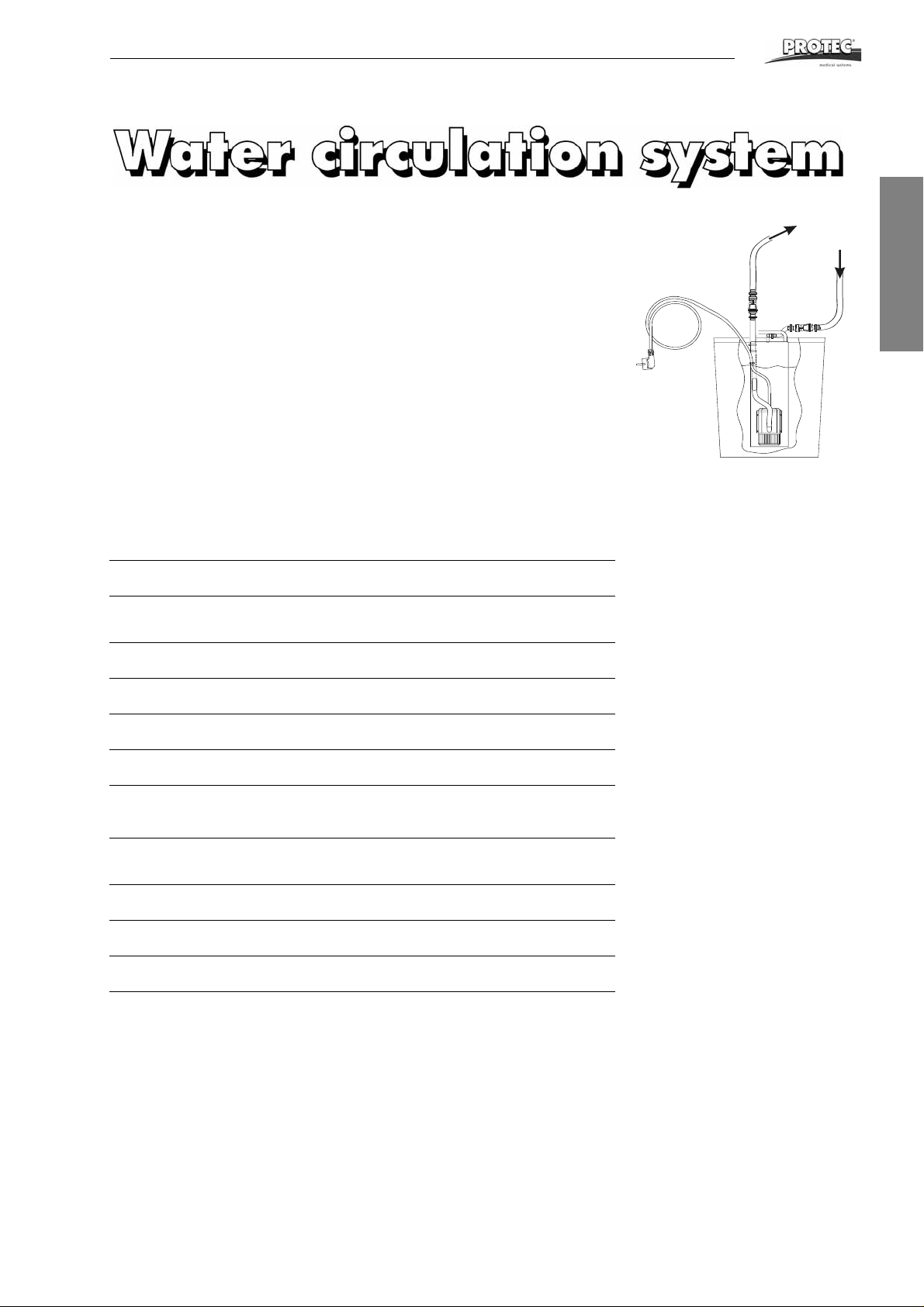
The water circulation system is a simple but effective accessory for installation sites
that do not offer permanent water supply connection. It is comprised of a water reservoir with integrated circulation pump and hoses with stop cocks. Due to the separate power supply connection the water circulation system is immediately ready to
operate. The proven circulation pump supplies the water from the reservoir to the
water bath of the machine. From there the water flows back to the water reservoir
via the overflow. A closed circuit results.
English
Technical Specifications
Tank volume:
Circulation system:
Noise level:
Pump volume:
Max. pumping height:
Water connection:
Environmental conditions:
Electrical connections:
Power consumption:
Weight:
Floor space required:
25 litres
Water is circualted by a rotary pump installed
between water reservoir and water bath
Less than 58 dB(A)
60 l/h
1000 mm
No supply connection required
Room temperature, 18-40°C
220 V/50 Hz or 220 V/60 Hz
110-120 V/60 Hz
10 W
5 kg empty, 30 kg filled
0.03 m²
ECOMAX
TM
23
Page 24

24 ECOMAX
TM
Page 25

Service Manual
Table of Contents
Installation Data ...................................................... .. .........................................26
Trouble Shooting ...............................................................................................27
Spare Parts......................................................................................................... 33
............................................................................................................................. 40
English
ECOMAX
TM
25
Page 26
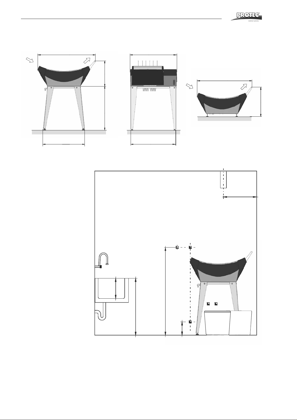
Installation Data
59cm (23.3’‘)
66cm (26.0’‘)
64cm (25.2’‘)
Optional
processor stand
(accessory)
1
2
457
3
8
5
c
m
(
3
4
2
0
c
m
(
8
’
‘
)
50cm (20’‘)
60x40cm (24x16’‘)
8
6
1. Wall socket
220-240 V, 16 A or 1 10 V, 15 A
(depending on machine
model). Power supply should
be equipped with earth-leakage breaker, 25 A / 30 mA
nominal fault current. In addition, a power control switch
can be installed.
2. Fresh water connection 3/ 4”
with stop cock, permissible
pressure 2-10 bar, water temperature 5-25 °C.
3. Drainage plastic pipe PVC ý
50 mm (2“) incl. syphon.
4. Drainage or collecting containers for used developer.
5. Drainage or collecting containers for used fixer.
6. Storage location for replenishment tanks: Below machine or
externally.
7. Ventilation of darkroom is
required.
8. Sink with freshwater and flexible hose. Inner dimensions
minimum (LxWxH)
60x40x30 cm (24x16x12“).
Sink
Darkroom
Measures and positions are recommendations
46cm (18.2’‘)
88cm (34.7’‘)
Installation Data
88cm (34.7’‘)
37cm (14 .6’‘)
70cm (27.6’‘)
26 ECOMAX
)
‘
m
’
c
2
0
1
(
3
)
‘
’
1
5
(
m
c
0
)
‘
’
3
1
TM
Page 27

Trouble Shooting
Trouble Shooting
Summary
1 Algae............................................................................................................ 27
1.1 Excessive algae growth in water tank ................................................... 27
2 General ........................................................................................................28
2.1 Unit does not switch on.........................................................................28
3 Drive............................................................................................................. 28
3.1 Film transport not running .....................................................................28
3.2 Machine does not start automatically.................................................... 28
3.3 Machine doesn't stop automatically....................................................... 28
3.4 Film transport does not function, fan runs............................................. 28
3.5 Machine stops before film comes out....................................................28
3.6 Relation between processing time and developer temperature ............ 29
3.7 Changing the transport speed............................................................... 29
4 Chemicals Baths......................................................................................... 29
4.1 No circulation in bath............................................................................. 29
4.2 Developer temperature too high............................................................30
4.3 Developer temperature too low .............................................................30
4.4 Developer temperature too low, fixer temperature too high .................. 30
4.5 Calibration of developer temperature.................................................... 30
5 Film defects.................................................................................................30
5.1 Films will not dry....................................................................................30
5.2 The film does not transport correctly..................................................... 30
5.3 Scratches, pressure marks, dirt on film................................................. 30
6 Replenishment............................................................................................31
6.1 Replenishment pump does not work or works insufficiently.................. 31
6.2 Replenishment volume too high or too low ...........................................31
6.3 Adjusting the replenishment pump........................................................ 31
7 Dryer ............................................................................................................31
7.1 Dryer fan does not run or runs with too slowly......................................31
8 Water............................................................................................................ 32
8.1 Rinsing water does not flow .............................................................. ... .32
8.2 Water tank overflows................................................................... .......... 32
English
1Algae
1.1 Excessive algae growth in water tank
• Algae growth inside the water tank is not only anoying, it causes increased
cleaning work and leaves residues on the films. If algae growth becomes
excessive, corrective measures must be taken:
• When work has been completed at the end of the day, drain water out of
the machine.
• Clean dryer-water rack regularly. Use soft sponge and soap to remove residue from the rollers.
• Install a particle filter system in the fresh water supply for the processor.
• If water tank overflows due to algae growth blocking the overflow hose,
then the overflow hose can directly be connected to the connection at the
water tank inside the machine.
• If no other solutions can be found, use of anti-algae agents can result in
improvement (automatic dispensers work the best). However, it is known
that cleaning agents containing chlorine may corrode rubber rollers and
high-grade steel in the tank area (check before use).
ECOMAX
TM
27
Page 28
Trouble Shooting
2 General
2.1 Unit does not switch on
• Ensure that the power socket conducts power.
• Check machine fuse in main switch.
• While power switch is on, check the following components: Volt age on
contact of main switch - if no voltage: - change main switch. Check input
voltage at electronics. If the voltage is normal, exchange the electronics. if
no voltage: check the cable wiring harness.
Do only use original PROTEC ®' fuses with gilded caps as replacement part. They are optimzed for use with PROTEC proc-
essors.
3Drive
3.1 Film transport not running
• When placing processor cover on, the cover switch should be activated,
re-adjust if necessary.
• Cover switch does not switch when activated: Replace.
• Check drive motor: If voltage can be detected on motor, then motor is
defective.
• Check screwing of chain wheel on motor- and driveshaft.
3.2 Machine does not start automatically
• With the unit switched on, insert a film in the feed. If the LED begins to
flash, the film detection switch is okay; if not, check the position of the
actuator and replace the switch if required.
• Check the following parts: film detection switch, connecting cable for film
detection switch, electronics module.
• Check the connecting cables between the electronics module and slots of
the components (motor, dryer heating and solenoid valve). If the connections have no fault then the electronics module may be defective.
3.3 Machine doesn't stop automatically
• LED flashes continuously: Check positioning of the film switch actuator or
replace the film detection switch.
• Check the following parts: connecting cable of film detection switch and
electronics module.
3.4 Film transport does not function, fan runs
• Check screwing of chain wheels and run of chain.
3.5 Machine stops before film comes out
The follow-up time is the part of the processing time that follows passing of the film
detection switch. Activate the switch in the feed tray with a film and remove the film.
Measure the time until the processor stops automatically.
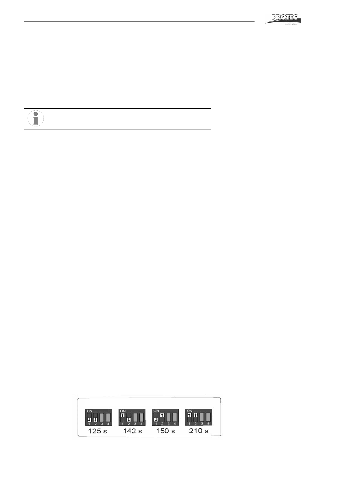
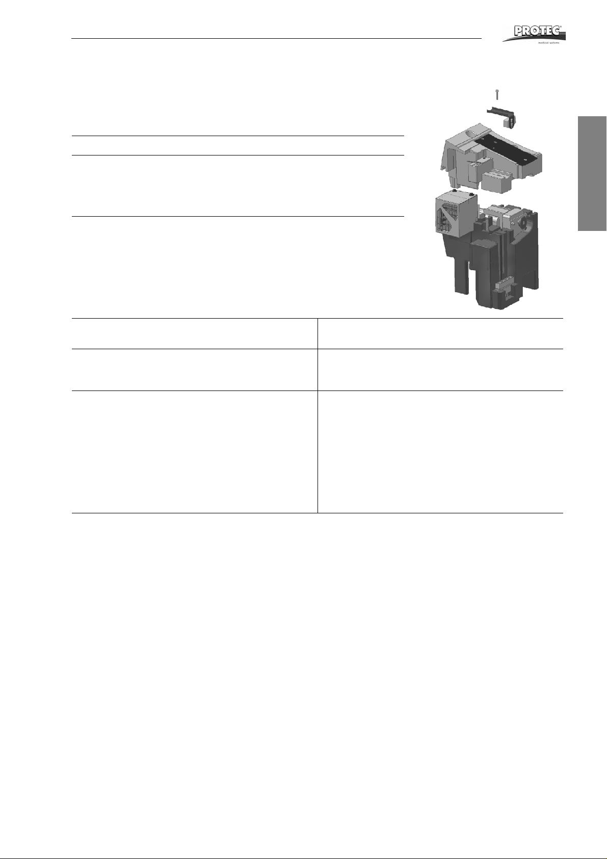
Change cycle time if necessary. The follow-up time can be set with a DIP switch on
the controller. When the unit is restarted after a change of the setting, the new programming will be saved. The figure below illustrates the setting options:
28 ECOMAX
TM
Page 29
Trouble Shooting
3.6 Relation between processing time and developer temperature
The following chart demonstrates guiding values for the relation between developer
temperature and processing time. Variations are possible depending on the various
films and chemicals. Changing the transport speed see 3.7.
Total processing time Developer temperature
105 s 32 °C - 34 °C
110 s 32 °C - 34 °C
117 s 32 °C - 34 °C
124 s 30 °C - 33 °C
3.7 Changing the transport speed
The processing speed can be changed by changing the gear wheels. The up per
EPAC must be removed. First loosen the screw on the chain tensioner. After removing the drive motor and the drive shaft, the chain wheels can be replaced. Note
that the follow-up time must be adjusted at the controller.
The following gear combinations are available:
English
220-240 V, 50 Hz versions
220-240 V, 60 Hz versions
tGmGs DIP
switch
positions
105 14 17 125 32,5 34,7 102 12 18 125 31,6 14,0
102 12 17 125 31,7 35,6 113 12 20 125 35,0 12,6
122 12 17 125 38,0 29,7 122 10 18 125 38,0 11,7
120 12 20 125 37,2 30,3 136 10 20 142 42,0 10,5
130 12 18 142 40,2 28,1 149 10 22 210 46,4 9,6
132 12 22 142 41 27,5
144 12 20 150 44,7 25,2
158 12 22 210 49,2 23,0
t = Processing time in seconds
Gm = Chain gear on motor shaft
Gs = Chain gear on drive shaft
Devel-
oper time
(s)
Feed
speed
(cm/min)
tGmGs DIP
110-120 V, 60 Hz versions
Devel-
switch
positions
oper time
(s)
speed
(in/min)
4 Chemicals Baths
4.1 No circulation in bath
• Circulation pump works but no circulation in bath: Air lock in heating and
circulation system. Vent the pump (see page 11 item 1c).
• Particles in the pump chamber. The pump chamber can be opened easily
by removing the four clips. When closing the pump, ensure that the rubber
seal is positioned correctly and not damaged.
• Check connection of pump, circulation pump possibly defective.
Feed
ECOMAX
TM
29
Page 30
Trouble Shooting
4.2 Developer temperature too high
• Check fastening of the temperature sensor of the temperature controller. It
must be seated firmly on the tube, must have been installed with heat
transfer grease, be covered by a silicone hose and be insulated with plastic foam.
• Temperature is set too high at the temperature controller: Set a lower temperature value by turning counterclockwise. (See “Calibration of developer
temperature” on page30.)
• If no error can be detected in the temperature sensor, the temperature
controller is defective.
4.3 Developer temperature too low
• Check circulation pump. Air lock in the circulation pump: vent pump (see
page 11). If no circulation can be detected: check wiring of circulation
pump, pump possibly defective.
• Bath is not heated: check temperature safety switch on heat-exchanger.
Check heating element: impedance across the element should reach
approx. 66 W.
• Check temperature sensor (see 4.2).
• If no other error can be detected, the temperature controller may be defective.
4.4 Developer temperature too low, fixer temperature too high
• Air lock in the circulation pump: vent circulation (see page 11).
4.5 Calibration of developer temperature
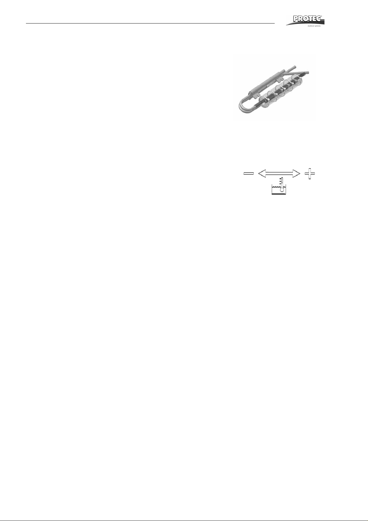
Temperature fluctuations can be compensated for by the temperature controller.
The controller is accessible from top. Remove the cover plate above the pumps.
Adjustment of the controller is expained on the drive shaft next to it (see figure)
5Film defects
5.1 Films will not dry
• No air comes out of air channel: check fastening of fan impeller, motor may
be defective.
• Cold air comes out of air channel: check wiring of heating element in the
air channel, heating element possibly defective.
• Hot air comes out of air channel, but the film is still not dried to satisfaction.
Check chemicals and film type. If this leads to no solution then the transport speed of the machine can be reduced (see Changing the transport
speed, page 29).
5.2 The film does not transport correctly
• Check the positioning of the racks in the machine and make sure that the
latches are closed.
• Check the roller racks: rollers are correctly seated and do not have excessive clearance, rubber springs are correctly seated, all gear wheels are
installed.
• Motor runs: the worm gear of the drive shaft should be secured with a split
pin to avoid twisting. Check the screws and positioning of the chain and
chain wheel.
5.3 Scratches, pressure marks, dirt on film
• Pressure marks caused due to polluted or damaged rollers. Check rollers
for visible damage. Rubber rollers sometimes swell up. Replace defective
rollers.
30 ECOMAX
TM
Page 31
Trouble Shooting
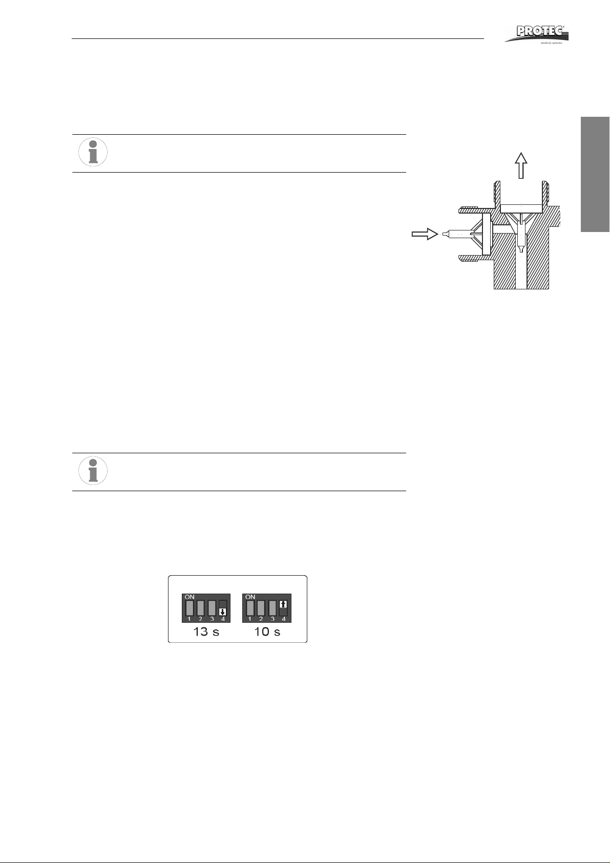
• Clean valves inside connection tube of pump.
Install valve-insert correctly: pay attention to flow direction!
6Replenishment
6.1 Replenishment pump does not work or works insufficiently
• Check filter in the suction pipe (repl. container) and clean it if necessary.
• Replenishment pump sucks in air. Check hoses and connections.
• Check position of eccenter. Flow rate reads 240 ml/min at maximum
eccenter position 100%.
• (60 Hz: 240 ml/min at 85 %)
• Measure the voltage between X3 and X4 directly after power-up of the unit
or after the film detection switch has been actuated for 40 seconds. If no
voltage can be measured, replace the power section.
6.2 Replenishment volume too high or too low
• The replenishment volume can be changed by altering the pump stroke or
in the controller.
6.3 Adjusting the replenishment pump
• To do this, the eccenter on the replenishment pump must be adjusted.
Maximum pump capacity is 240 ml/min (100 %). For adjustment of the
eccenter first open the socket hex screw on the large eccenter with the red
mark. If the screw is not accessible, switch the machine on briefly. Switch
the machine off as soon as the screw becomes accessible.
• Turn the eccenter so that the red mark will be at the desired position, then
fasten the socket hex screw.
English
Do not set the eccenter below 75 %.
6.4 Setting the replenishment volume in the controller
The replenishment volume can be changed by altering the pump run time per cycle.
To do so, set the DIP switch on the cotroller to either 10 s or 13 s (Compare figure).
When the machine is restarted the new programming becomes active.
7Dryer
7.1 Dryer fan does not run or runs with too slowly
• Check whether the threaded pin fastening the fan wheel to the rotor shaft
of the motor has loosened.
• Check whether the motor is defective.
ECOMAX
TM
31
Page 32
Trouble Shooting
OFF
ON
8 Water
8.1 Rinsing water does not flow
• The water pressure in the water supply system is too low: Minimum pressure 2 bar (29 psi).
• The valve opens, but no water flows through: the coarse filter on the intake
end is blocked.
• Check the water supply hose in the machine.
8.2 Water tank overflows
• The water drainage hose (overflow) should be laid out with constant
descent. The hose end should be positioned above the drainage level in
the syphon.
• Check water drain opening in the tank and the hose for blockage and residues.
• When extreme algae growth is registered, the overflow can be connected
directly to the fitting of the water tank.
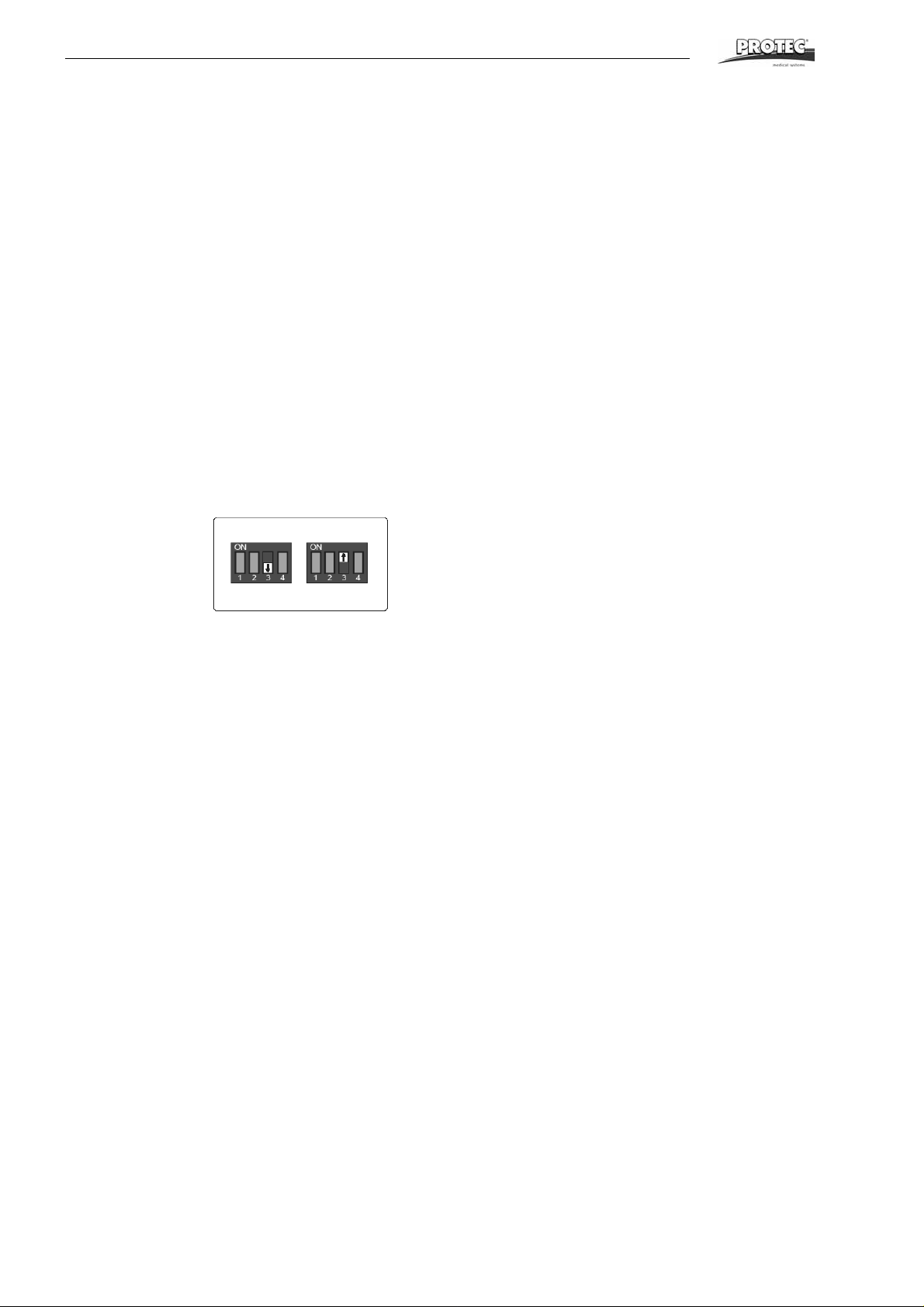
9 Shutting off time-controlled replenishment / anti-oxidation
The anti-oxidation function can be shut off at the controller. To do so, set the DIP
switch on the controller as shown in the figu re .
Antioxi dation 5s / 20min
32 ECOMAX
TM
Page 33
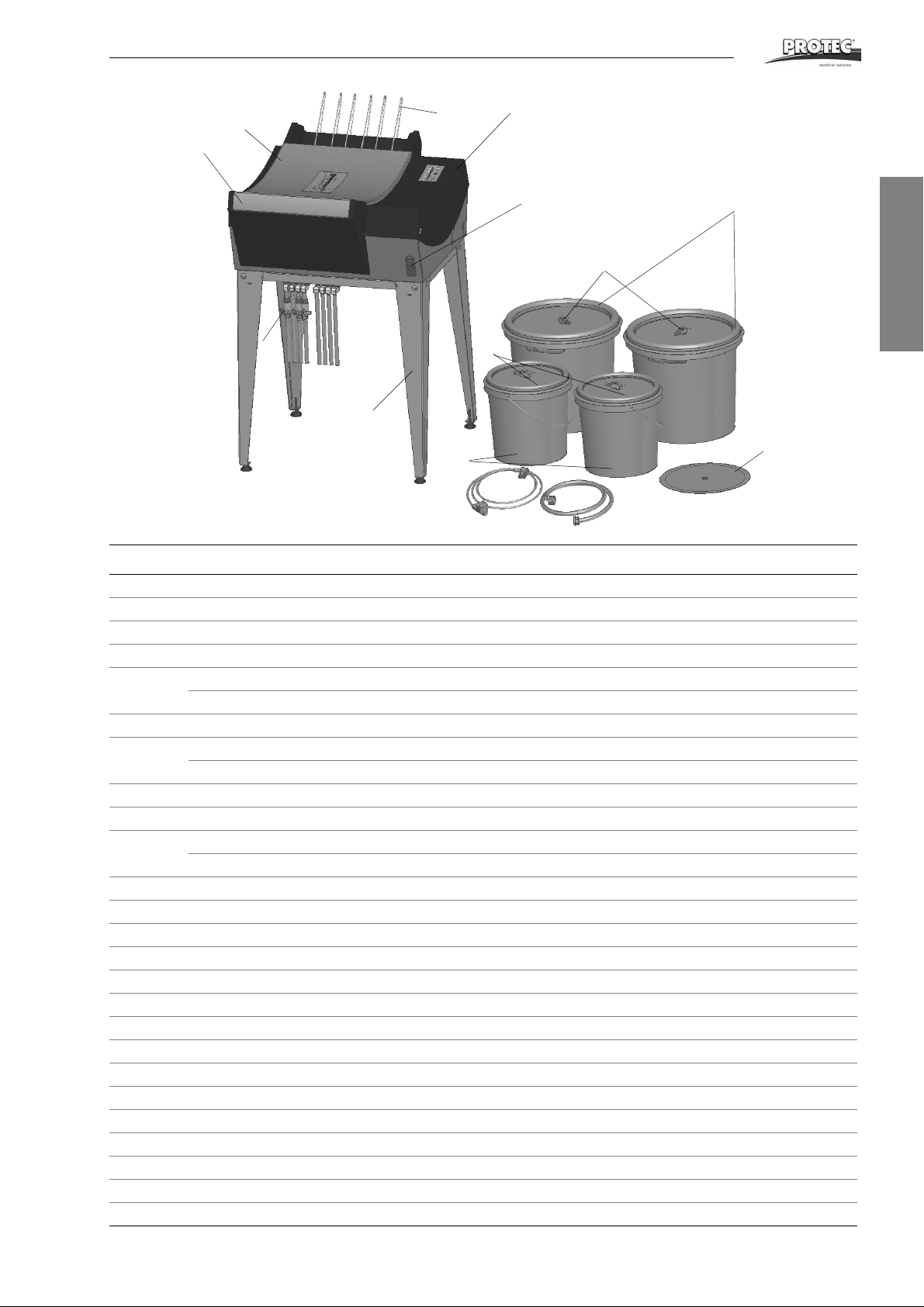
Spare Parts
1
2
3
4
8
7
9
6
10
12
5
11
13
15
Spare Parts
English
Pos. Order No. Description:
1 1186-0-0200 Service cover, complete
2 1186-0-0201 Cover
3 1186-0-3100 Light protection cover, complete
4 2006-0-0005 Ball-type stop cock 10 mm
5 1170-0-2000 Replenishment tank, 12 l dev.
1170-0-2100 Replenishment tank, 12 l fix.
6 1170-0-1760 Suction pipe with filter for 12 l vessel, round
7 2004-0-0003 Electrical power cable 220-240 V
2004-0-0021 Electrical power cable 220-240 V
8 2018-0-0001 Water inlet tube
9 1286-0-0000 processor stand
10 1101-0-2000 Replenishment tank 25 l dev.
1101-0-2100 Replenishment tank 25 l fix.
1 1 1101-0-1700 Suction pipe with filter for 25 l vessel
12 1101-0-4100 Floating cover developer
13 1170-0-1400 Combination unit switch
14 2010-0-0010 Fusible, gold, T 10 A / 250 V UL
15 1186-0-0805 Bracket, film outlet
- 2018-0-0012 Hose 10 x 2 mm, celar, reinforced
- 2018-0-0009 Hose 10 x 2 mm, blue, reinforced
- 2018-0-0008 Hose 10 x 2 mm, red, reinforced
- 2018-0-0005 Hose 4 x 1 mm, green
- 2018-0-0021 Hose 9 x 2 mm, red, transparent
- 2018-0-0022 Hose 9 x 2 mm, blue, transparent
- 2022-0-0004 Tube clamp
- 2022-0-0019 Wire tube clamp
- 1101-0-4600 Floating balls, 300 pcs.
- 1101-0-4800 Floating balls, 200 pcs.
ECOMAX
TM
33
Page 34
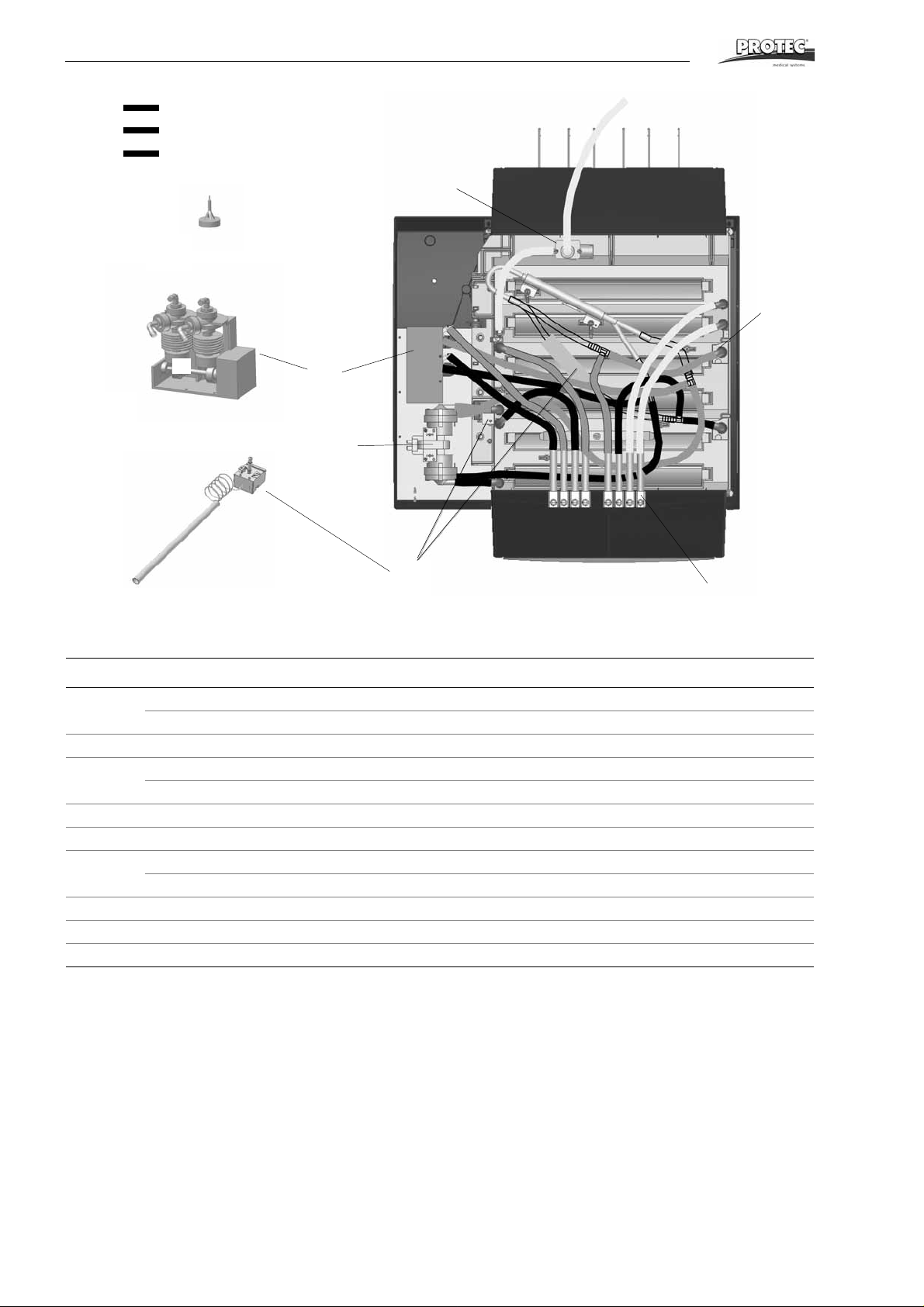
Spare Parts
20a
20
20
Fixer:
Developer:
Water
21
25
24
23
22
Pos. Order No. Description:
20 0202-1-0008 Replenishment pump 2KBA 220-240 V, 50/60 Hz
0202-6-0008 Replenishment pump 2KBA 115 V, 50/60 Hz
20a 0002-1-0008 Conical valve for pos. 20
21 2002-1-0013 Circulation pump 220-240 V, 50/60 Hz
22 1160-0-0702 Elbow fitting
23 1160-0-0710 Rubber hose stub
24 2006-5-0004 Solenoid valve 220-240 V, 50/60 Hz
25 0186-0-2200 Temperature controller set
- 1186-0-1250 Wiring harness 230 V
- 1186-0-1251 Wiring harness 115 V
2002-6-0013 Circulation pump 110 V, 50/60 Hz
2006-6-0003 Solenoid valve 110 V
34 ECOMAX
TM
Page 35
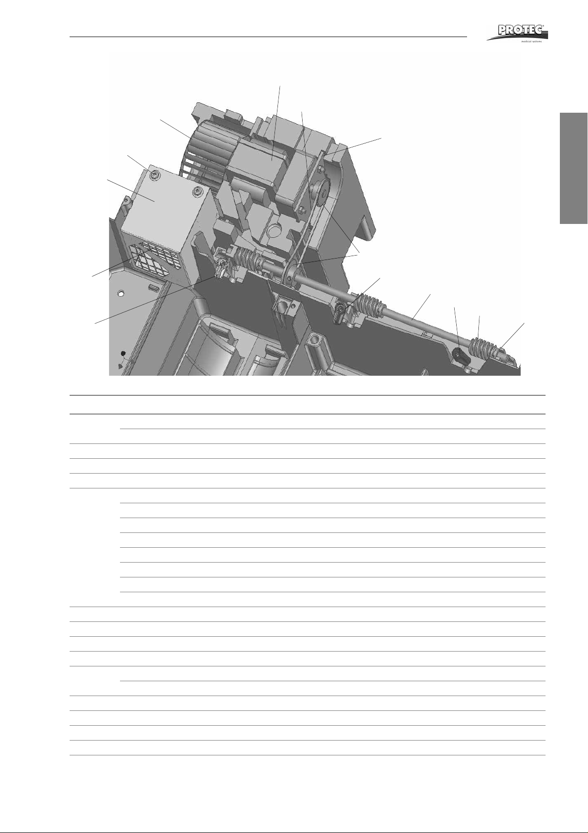
Spare Parts
26
27
28
31
32
30
29
35
33
36
34
38
37
39
English
Pos. Order No. Description:
26 2001-0-0003 Main drive motor 220-240 V, 50 Hz
2001-6-0003 Main drive motor 120 V, 50/60 Hz
27 1186-0-1101 Motor plate
28 1186-0-1501 Drive shaft worm-gear
29 1170-0-1503 Worm-gear
30 1186-0-1502 Chain wheel t=10
1170-0-1506 Chain wheel t=12
1170-0-1504 Chain wheel t=14
1170-0-1505 Chain wheel t=16
1170-0-1102 Chain wheel t=17
31 2037-0-0003 Roller chain
32 3000-9-4013 Splint pin 2.0 x 20 mm, inox
33 2008-0-0001 Fan impeller TLR 85x52
34 1186-0-1302 Air channel
35 0186-5-1300 Heating element Ecomax 230 V, 900 W
36 1101-0-0146 Latch, red
37 1101-0-0141 Latch, blue
38 1101-0-0113 Latch, plain
39 2009-0-0019 Rivet
ECOMAX
1170-0-1507 Chain wheel t=18
1186-0-1503 Chain wheel t=20
1186-0-1504 Chain wheel t=22
0186-6-1300 Heating element Ecomax 110 V, 900 W
TM
35
Page 36
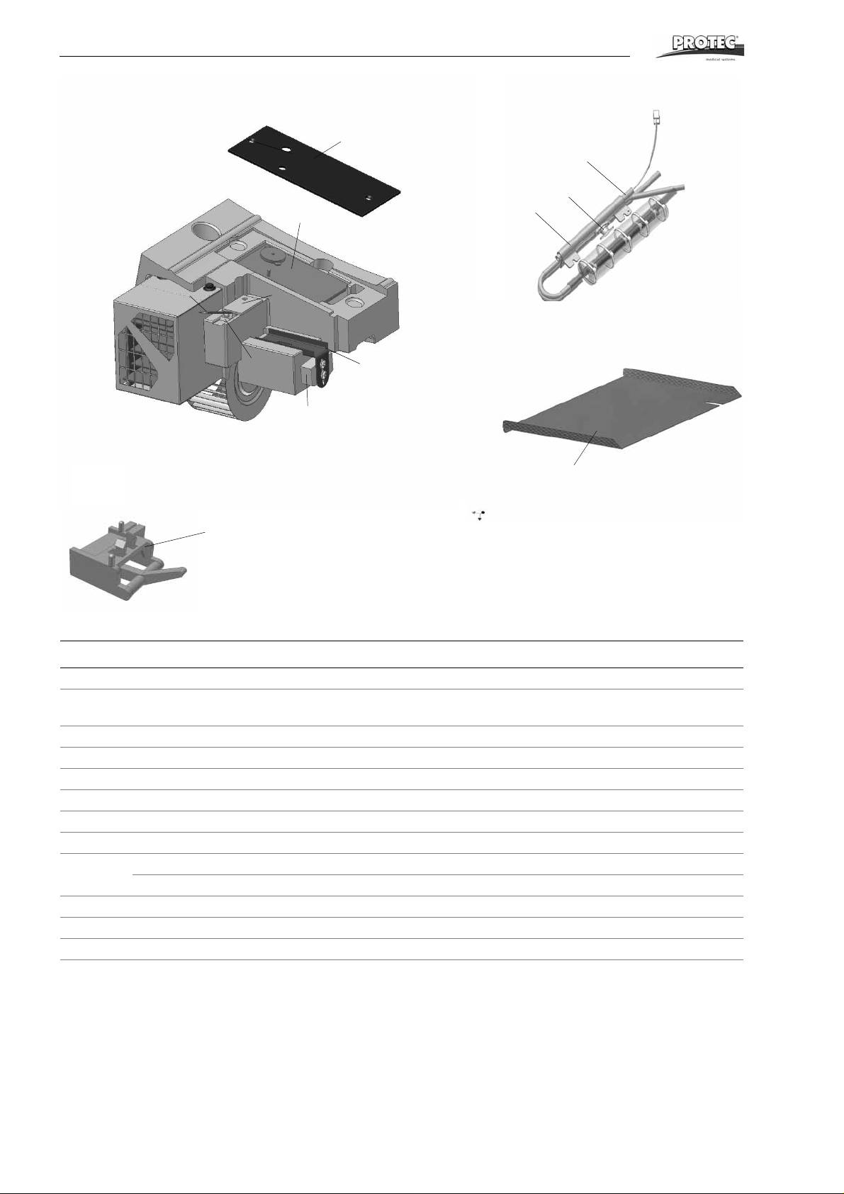
Spare Parts
40
41
44
42
45
43
46
48
50
49
47
51
Pos. Order No. Description:
40 1186-0-1301 Controller cover plate
41 1186-5-1300
1186-6-1300
42 2007-0-0001 Micro switch 83.161-6 N/O W3
43 2007-0-0010 Actuator for micro-switch
44 1186-0-0502 Inlet cover
45 1186-0-0701 Chain tensioner
46 1186-0-0702 Bracket for chain tensioner
47 1186-0-0802 Film feed tray
48 2003-5-0010 Heating element 230 V, 300 W
2003-6-0002 Heating element 120 V, 400 W
49 1130-0-2101 Heat exchanger
50 2005-0-0005 Temperature limiter
51 2007-0-0005 Film detection switch
Controller 230 V
Controller 110 V
36 ECOMAX
TM
Page 37
Spare Parts
110
107
100
109
104
103
109
101
114
115
113
111
106
108
108
107
112
102
105
English
101
110
Standard roller racks
ECOMAX
TM
37
Page 38

Spare Parts
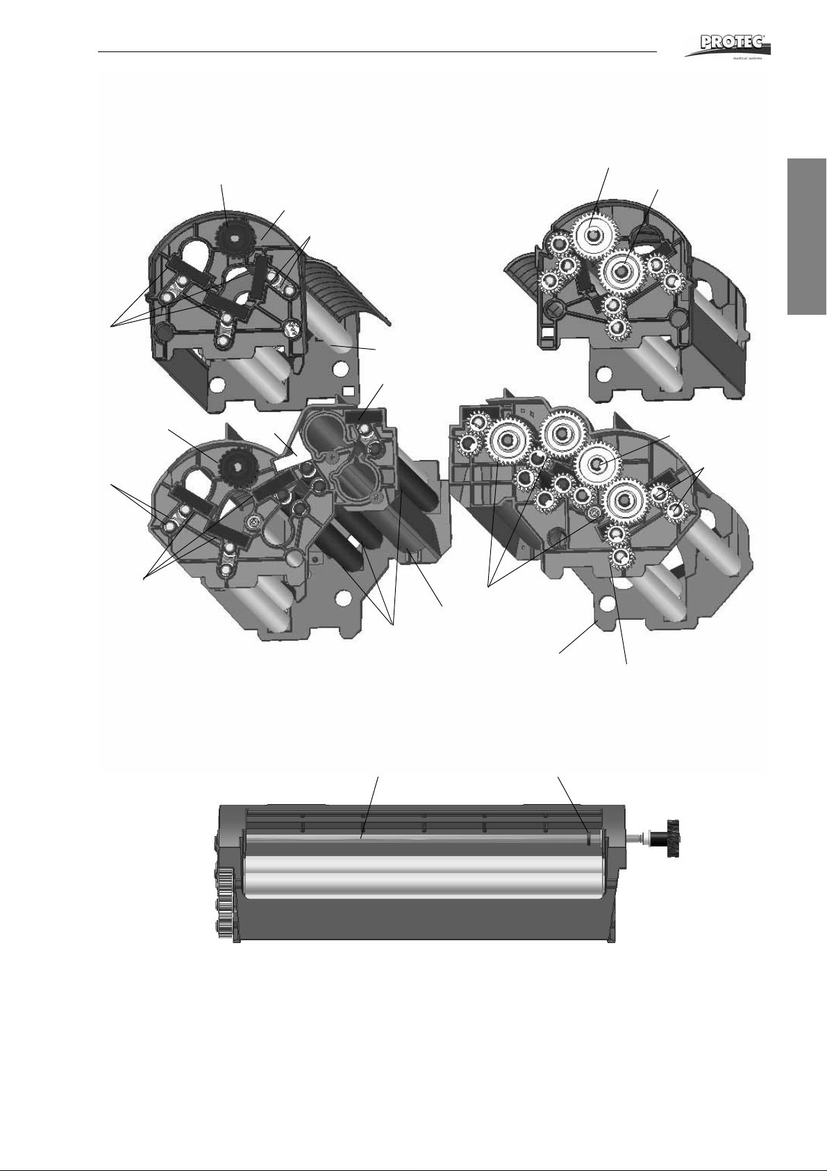
Pos. Order No. Description:
Standard Processor
- 1186-0-0300 Roller rack, developer
- 1186-0-0400 Roller rack, fi xer
- 1186-0-0600 Roller rack, dryer
100 0186-0-0303 Roller support, dev. with axles
0186-0-0403 Roller support, fix. with axles
101 1186-0-0304 Rubber spring element, black 36.5 x 10 x 6
102 1186-0-0306 Rubber spring element, white
103 1186-0-0307 Rubber spring element, black 31 x 10 x 6
104 1140-0-0301 PU-roller 35 ground
105 1170-0-0310 Drive shaft rack
106 1101-0-0302 Gear t = 16, D-hole
107 1101-0-0304 Gear t = 32, round hole
108 1101-0-0303 Gear t = 32, D-hole
109 1170-0-0302 Worm wheel
110 1101-0-0305 Bearing bush
111 2014-0-0001 Circlip
112 2014-0-0003 Clamping ring
113 0186-0-0603 Roller support, dryer with axles
114 1140-0-0302 Rubber roller 35
115 1140-0-0605 Air jet (35)
38 ECOMAX
TM
Page 39
Electric Diagrams
Electric Diagrams
English
ECOMAX
TM
39
Page 40
Electric Diagrams
40 ECOMAX
TM
Page 41
Electric Diagrams
English
ECOMAX
TM
41
Page 42
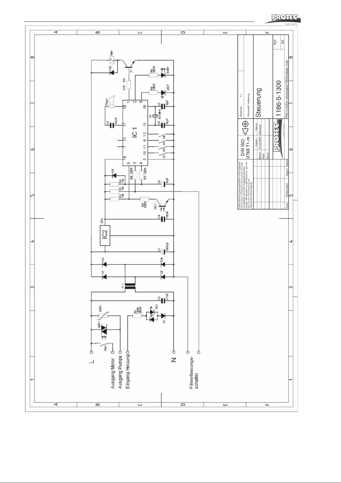
Electric Diagrams
42 ECOMAX
TM
 Loading...