

Page 1
Automatic Mixer
Operating Instructions
English
PROTEC® Medizintechnik GmbH & Co. KG
Lichtenberger Strasse 35, D-71720 Oberstenfeld, Germany
Telephone: +49-7062-9255-0 e-mail: [email protected]
Machine No.:
Type:
Installation Date:
Status : June 2004/3.0
Subject to change
Page 2

EU-Declaration of Conformity
EU-Declaration of Conformity
PROTEC® Medizintechnik declares, that the product
Description:
Machine type:
Model no.
conforms to the following harmonized standards:
PROMIX A40
Automatic Mixer
1180-1-0000, 1180-2-0000
®
®
Safety:
EMC:
according to the regulations of:
EN 61010-1 (VDE 0411 Part 1, 03/1994); DIN 1988 T4,12/1988
EN 50081 Part 1, 03/1993; EN 50082 Part 1, 03/1993
• the Medical Device Directive 93/42/EEC “Class 1”,
• the Low Voltage Directive 73/23/EEC and the
• EMC Directive 89/336/EG
PROTEC® Medizintechnik GmbH & Co. KG, Lichtenberger Strasse 35, D-71720 Oberstenfeld, Germany
Place and date of issue:
Oberstenfeld, 12th January, 1999 Jochen Krupp (Technical Manager Analog Systems)
2 PROMIX A40
®
Page 3

Table of Contents
Introduction .......................................................................................................... 3
Technical Specifications ..................................................................................... 4
Safety Instructions............................................................................................... 5
Installation ............................................................................................................ 6
Operation .............................................................................................................. 8
Bottle Opener ..................................................................................................... 11
Cleaning and Maintenance................................................................................ 12
Advice on Unit Errors ........................................................................................ 13
Service Manual as appendix, see page
Changing the Mixing Volume / Setting the Mixing Times .............................. 14
Trouble Shooting ............................................................................................... 14
Connection Diagram .......................................................................................... 15
Spare Parts ......................................................................................................... 16
Electric Diagrams............................................................................................... 18
®
Copyright
© 2004 by PROTEC
olates the limitations set forth by copyright law, needs to be authorised in writing by
PROTEC
Information on Liability
This manual has been checked for correctness. The instructions and specifications
were correct at the time it was published. Future automatic mixers may have modifications without prior notice. PROTEC® Medizintechnik does not take responsibility for damage caused directly or indirectly by error, omission or non-conformity of
the manual.
®
Medizintechnik.
®
Medizintechnik. All rights reserved. Any reproduction that vi-
Introduction
The PROMIX A40® is a fully automatic chemical mixing machine for preparing developer and fixer bath chemicals of either powder form or liquid concentrates. All
stages are guided and controlled by means of a microprocessor. Thanks to a large
reserve tank, up to three machines can be connected and continue to operate, without having to interrupt the working process even during refilling.
®
Due to its patented design, the PROMIX A40
virtually service free. The robust magnetic circulation pumps are resistant to crystalisation and pollution and ensure fast and throrough mixing of the chemicals.
®
The PROMIX A40
These Operating Instructions contain important instructions for installation, operation and servicing of the machine. Please read the provided information carefully to
ensure reliable and satisfactory operation of your PROMIX A40
replaces the usual regenerator tanks in the darkroom.
is easy to operate, reliable, fast and
®
.
English
PROMIX A40
®
3
Page 4

Technical Specifications
Technical Specifications
®
Tank volume:
Reserve tank:
Mixing times:
Pump capacity:
Water connection:
Water intake:
Noise level:
Environmental conditions:
Pollution degree:
System protection:
each 40 litre maximum
Mixing volume 20, 25, 30 or 40 litres can be
adjusted by setting of float switches.
each 13 litres
variable, 2, 3, 5, 10, 15, 20, 25, 30 minutes
38 l/min
Admissible water pressure: 2-10 bar (29-145 psi),
Admissible water temperature: 5-30 °C (41-86 °F)
9 litres per minute and tank
Less than 55 dB(A)
1) Temperature 5-40 °C (41-104 °F), ventilated
room,
2) Relative humidity lower than 80 % up to 31 °C,
linearly decreasing to 50 % at 40 °C.
3) Height above sea level less than 2000 m
(6666 ft).
4) Indoor use
2
IP 20
Electrical connections:
Power consumption:
Weight (unit):
Dimensions (LxWxH):
Floor space required:
Electrical specifications are indicated on the model
nameplate.
Type 1180-1-0000: 220-240 V~, 1.1 A, 50 Hz.
Type 1180-2-0000: 220-240 V~, 1.1 A, 60 Hz.
Device acc. to IEC 1010 (EN 61010, VDE 0411)
overvoltage category II,
fuse protection: sb 2 A / 250 V
0.3 kWh
28 kg (61.7 lb) empty,
108 kg (238.1 lb) filled
height = 93 cm (36.6 '')
width = 65 cm (25.6 '')
depth = 44 cm (17.3 '')
2
0.29 m
(3.1 sqft)
4 PROMIX A40
®
Page 5
Safety Instructions
Safety Instructions
To ensure safe operation of the mixer, installation and use should always conform to the instructions contained in this manual.
Prevention of water overflow damages: When the machine cannot be supervised, the water supply tap should be shut off.
The developer and fixer chemicals used in the processor should be handled
according to the manufacturers instructions. In general: Undiluted chemicals are
caustic. For this reason, avoid skin contact and wear suitable equipment for personal protection, such as safety glasses and gloves when handling chemicals. If
chemicals have come in your eyes, rinse the eyes immediately with cold, running
water for approximately 15 minutes and contact a medical doctor afterwards.
Inhalation of chemicals can be dangerous to your health and should be avoided.
For this reason, always ensure that the room in which the processor is installed is
adequately ventilated.
Environmental regulations regarding the storage and disposal of waste chemicals should be obtained from the local water authorities and complied with.
®
English
Before opening the unit, switch off the unit and unplug it from the electrical
socket. Service and repairs must be performed by trained service technicians
only. Use only manufacturer´s replacement parts.
PROMIX A40
®
5
Page 6

Installation
Installation
1. Requirements for Installation
a. Fresh water connection: Shut-off tap, thread with 3/4" outside diameter (wash-
ing machine connection), Water pressure 2 - 10 bar (29 - 145 psi).
b. Drainage connection:
mum drainage rate 18 l/min.
Regulations for wastewater treatment by local authorities must be observed.
c. Electrical connection:
60 Hz, 2 A. It is recommended to install a control switch and fault current circuit breaker with 25 A / 30 mA rated fault current between power socket and
power cord.
Electrical connections should be carried out according to regulations by an electrician.
2. Set-Up
a. Unpack the unit and transport it to the installation site.
b. Connect the water supply hose (gray) to the prepared 3/4" shut-off tap.
c. Connect the processor´s replenishment connections to the replenishment
hoses. Pay attention to the colours: red = developer (left tank), blue = fixer
(right tank).
Plastic tube - inner diameter 50 mm (2”) or larger. Maxi-
Fused socket with earth connection 220 - 240 V, 50 or
®
Important!
To avoid damaging the connection fitting, fasten the replenishment hoses at the underside of the mixer using the cable
ties supplied (see sketch).
d. Connect the overflow hoses to the prepared drain siphon. Do not bend or kink
the hoses. Fasten the hoses using the cable ties supplied. The local regulations for drainage of wastewater must be observed.
e. After the mixer has been installed, a technician should check the function of
the water-stop switch. To do so, open the water tap and switch the mixer on.
As the water flows into the mixer, lift up the top float switch with your hands.
When you lift it to the upper position, the float switch must shut off the water
supply. Check this on both mixing tanks.
6 PROMIX A40
®
Page 7
Installation
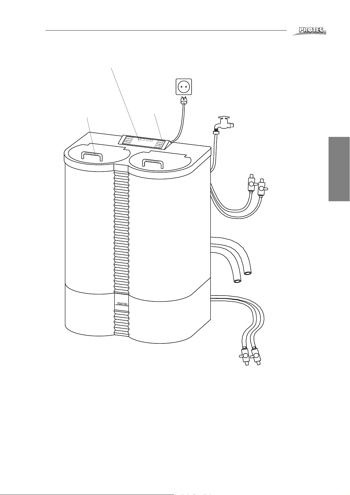
Controller section
Operation of the unit
®
Power connection
Cover flap
with funnel that can be taken out
P
R
O
m
Developer
mixing tank
i
x
A
4
0
Power switch
and fuse
Fixer
mixing tank
Water connection
Hand-held hose
for manual pumping.
Important! Keep the
shut-off tap closed (see
page 9).
English
Emergency
overflow
Developer
reserve tank
Fixer
reserve tank
Please note that the buttons for operation, the hand-held hoses
and the covers of the mixing tanks are colour-coded.
RED = developer (left mixing tank)
BLUE = fixer (right mixing tank)
PROMIX A40
®
Replenishment hoses
connect to
replenishment
connections at the
processor.
7
Page 8
Operation
Operation
®
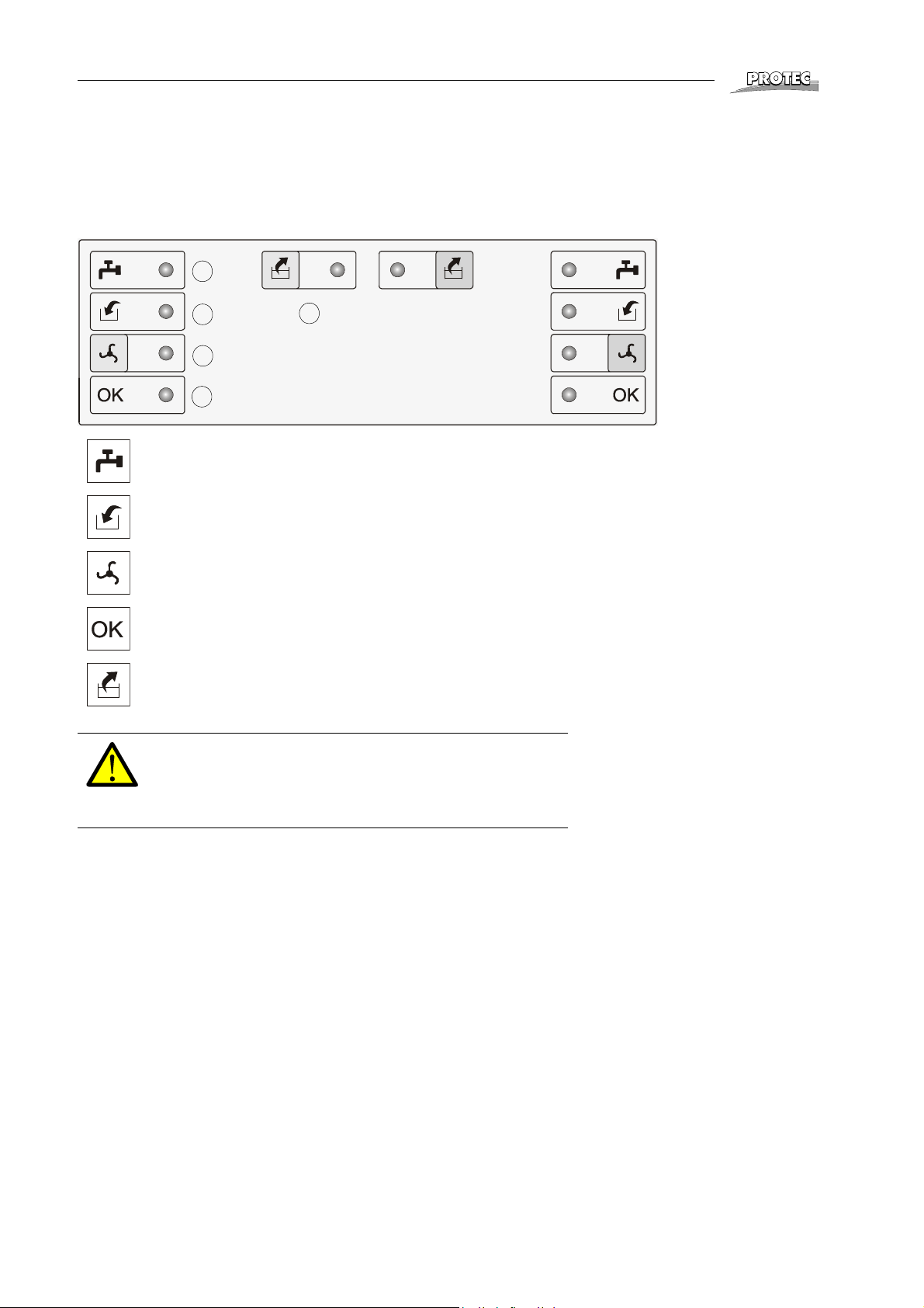
Display and buttons for the developer mixing
tank (red)
1
2
3
4
Water supply
Display flashing: open tap or leave it open.
Add chemicals
Display flashing: add chemicals to the respective mixing tank.
Mix
Button starts the mixing process after chemicals have been added.
Mixing completed / Stand-By
Display on: Mixing process is complete, close water tap.
Developer:
5
Display and buttons for the fixer mixing tank
(blue)
Fixer:
Pump On/Off
Button for manual pumping of chemicals.
Important!
Do not switch the unit off during the mixing cycle. This could
result in partially mixed chemicals flowing into the reserve
tank. Prepare fresh chemicals only when the mixing tank is
empty. Prepare chemicals in the correct tank!
Preparing the Chemicals
When the mixing tank is empty, chemicals can be prepared.
1. Open the water supply tap and close the shut-off taps on the hand-held
hoses.
2. Switch the unit on at the power switch. The mixer now automatically fills with
water. A beeping sound occurs at an interval and the display Water supply (1)
flashes.
3. When the mixer has filled up to half full, the water supply stops for a moment.
(At the end of the mixing process, more water will be filled in, therefore leave
the tap open.)
4. The display Add chemicals (2) flashes and a continuous beep is heard. Open
the cover flap and fill the powder or liquid concentrate into the respective mixing tank; observe the manufacturer´s instructions.
8 PROMIX A40
®
Page 9
Operation
5. After filling in all the components of the chemicals, press the Mix button (3) to
start the mixing process. The Mix display is on during mixing.
6. After the initial mixing phase, more water is added until the final level is
reached (20, 25, 30 or 40 l). The second mixing cycle completes the mixing
process. The Mixing completed display (4) indicates that mixing is complete
and the unit has changed to stand-by mode. Close the water supply tap now.
The ready mixed chemicals now flow into the reserve tank. This can be seen
by the dropping liquid level in the mixing tank.
Stand-By Mode
In stand-by mode the mixer monitors the filling level of the chemicals. When the
chemicals in the mixing tank have been depleted (reserve tank is still full), an interval sound is heard and the Water supply display (1) flashes. Open the water supply
tap and start preparing the chemicals as described above.
Important!
Keep the cover flaps of the mixer closed at all times to prevent
the chemicals from oxidizing or crystallizing. This will also
prevent unpleasant odours from the chemicals.
Manual Pumping Off / Mixing
To fill the processor, e. g. when new chemicals have been prepared, the chemicals
can be pumped out of the mixer manually, using the hand-held hoses. To do so,
switch the pump on with the Pump On/Off button (5). To pump out chemicals, open
the shut-off tap on the hand-held hose. Upon completion, be sure to close the shutoff tap on the hand-held hose and switch off the pump.
®
English
Important!
The shut-off tap on the hand-held hose must always be closed,
unless you are just pumping out chemicals. If the shut-off tap
is open during the mixing process, chemicals will escape!
This function can also be used to start an additional mixing process manually, e. g.
when hardener or additives are added. Keep the shut-off tap on the hand-held hose
closed. Switch the pump on. The mixing process automatically stops after 15 minutes, but can be stopped at any time before by pressing the Pump On/Off button(5).
Important!
Do not shift the PROMIX A40
Handle all connections with care to prevent damage.
Attention!
The distance between the PROMIX A40
X-ray film must be sufficient, because the LED of the display
can otherwise cause exposure of the film.
®
when it is filled!
®
and an undeveloped
PROMIX A40
®
9
Page 10

Operation
Setting the Mixing Time
The mixing time is set using the operating elements.
®
2 min.
3 min.
5 min.
10 min.
To change the mixing time, proceed as follows:
1. Switch the unit off.
2. Press one of the two buttons Mixing (developer or fixer) and while keeping it
pressed switch the unit on.
3. The respective LED´s light up to indicate the set mixing time.
4. By pressing the Mixing button repeatedly, change the mixing time. The adjustable mixing times are selected one after the other: 2, 3, 5, 10, 15, 20, 25 or 30
minutes. The number of LEDs that are on, correspond to the mixing time (see
sketch).
The set mixing time applies to the developer and
Only change the mixing time when the OK display is on or the mixing tank is empty,
that is, by no means after fresh water for a new mixing process has already been
filled in. While settings are made, the solenoid valve and pump are shut off. Therefore, do not change the mixing time while the mixer fills with water or during the mixing process, as this could dilute the chemicals in the reserve tank.
fixer mixing processes.
15 min.
20 min.
25 min.
30 min.
10 PROMIX A40
®
Page 11
Bottle Opener
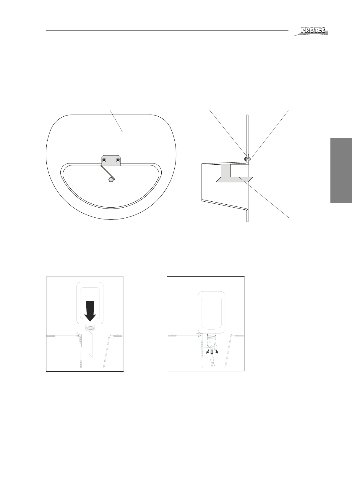
Bottle Opener
Installation
If you are using liquid chemicals supplied in bottles with membrane cover, the bottles can be opened easily and without splashing using the bottle opener. Fasten the
bottle opener supplied inside the filling funnel as shown in the drawing.
Filling funnel Nut Screw
®
English
Use of the Bottle Opener
Place the bottle vertically onto the tip of the bottle opener and press it down.
On bottles with strong plastic covers, place the bottle on the bottle opener so that
the tip of the opener rests in the groove in the cover provided for this purpose.
Bottle opener
PROMIX A40
®
11
Page 12

Cleaning and Maintenance
Cleaning and Maintenance
If necessary, the mixer can be cleaned. Wipe the outside surfaces with a wet cloth.
Use lukewarm water, but no cleaning agents or solvents. The filling funnel for the
powder should be removed and cleaned regularly.
Intermissions
Before going on holiday or when the mixer will not be used for a longer period of
time, the chemicals can be pumped out of the mixing tank. This may be done using
the mixing pump (see “Manual Pumping Off / Mixing” on page 9). The chemicals in
the reserve tank do not need to be pumped out. They can be stored therein for several weeks.
®
12 PROMIX A40
®
Page 13

Advice on Unit Errors
Advice on Unit Errors
Your automatic mixer has been designed for intensive long-term use. However, if
irregularities occur, you will find help to locate the problem below. Please check the
listed points, before calling your service-technician.
Mixer does not switch on
• Plug the power plug firmly into the socket. Ensure that the power socket conducts power by testing with an appliance (e. g. tablelight).
Mixing process does not start automatically
• One of the float switches in the mixing tank has gotten stuck in the upper position.
No water is supplied
• Open the water supply tap.
• Water pressure in the supply system is too low.
Faulty preparation of chemicals
• Upon a faulty preparation of chemicals you can drain the reserve tank by
opening the shut-off tap on the replenishment hose. Before opening, shut off
the processor connected and separate it from the mixer. Otherwise the
replenishment pumps might draw in air. Rinse the mixer thoroughly several
times!
®
English
Chemicals not adequately mixed
• Powder concentrate has been stored badly, may be damp and lumpy, causing
a bad mixing result. Start an additional mixing cycle by pressing the Pump On/
Off button. After 15 minutes mixing time the pump shuts off (see page 9).
All displays on, water supply indicator flashes
• When the mixing tank was empty, water supply was started, but the half full
level has not been reached after 30 minutes. The water supply tap has not
been opened or the water pressure is insufficient. To reset the error message,
switch the unit off.
All LEDs are flashing
• The bottom float switch has gotten stuck. Loosen the bottom float switch and
switch the unit off to reset the error.
PROMIX A40
®
13
Page 14

Trouble Shooting
Service Manual
Changing the mixing volume
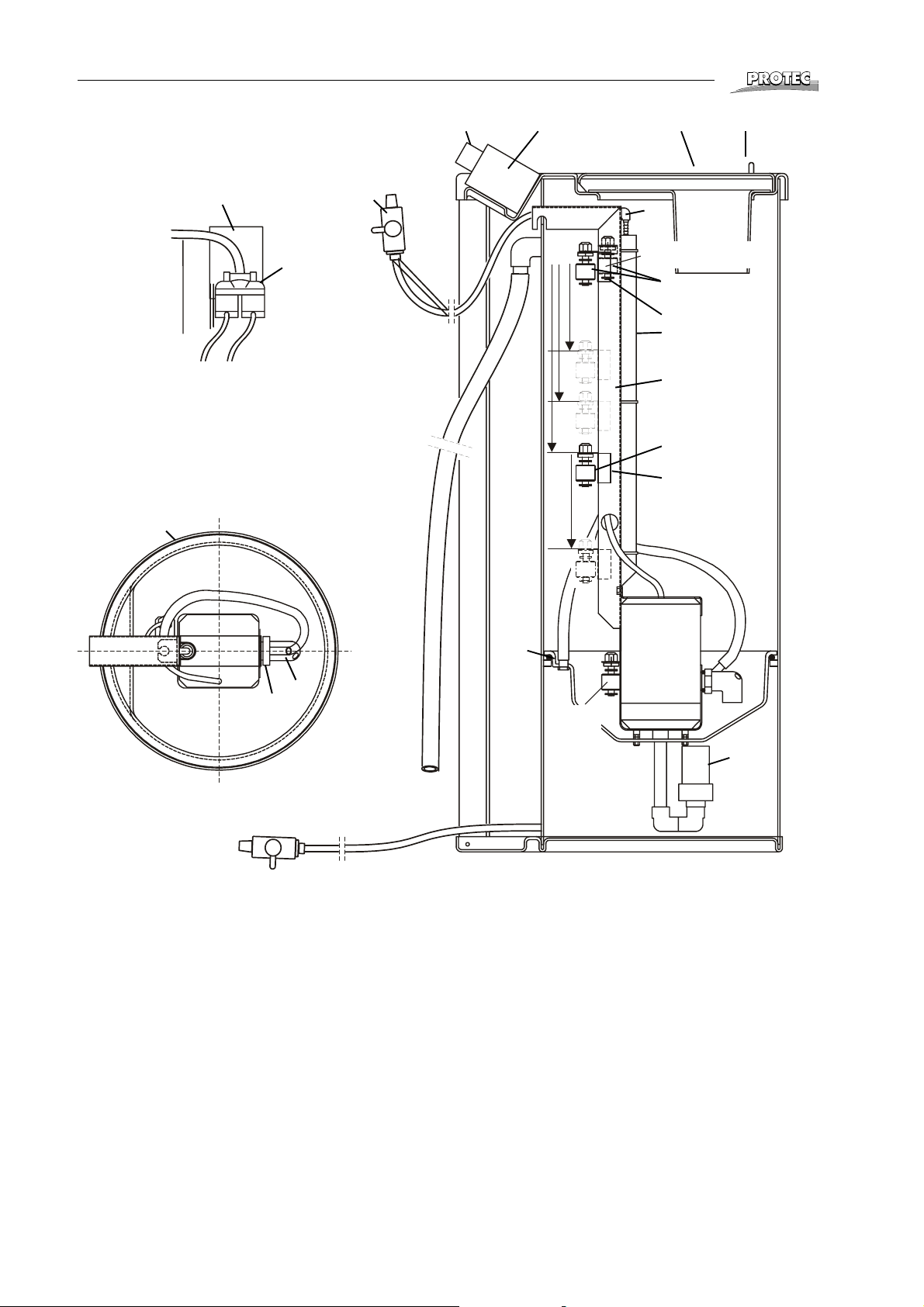
• If you wish to change the mixing volume, the position of the two centre float
switches must be changed. The respective positions are indicated in the
drawing on page 16.
Setting the mixing times
• The mixing times can be set using the mixing buttons (developer or fixer, see
page 10). The mixing time must be set to fit the volume mixed (20, 25, 30 or
40 litres) and the type of chemicals used (liquid concentrate or powder). A
smaller volume with liquid concentrate generally requires a shorter mixing
time (see page 10).
Trouble Shooting
Unit does not switch on
• Ensure that the power socket conducts power.
• Check the unit´s fuse in the controller housing.
• Check the continuity of the power switch, replace the power switch if necessary.
®
Unit does not start, no water flows in
• The float switches are not connected or the cables are interrupted.
• The float switch has gotten stuck in the upper end position.
• The electronic controller is defective, replace.
Water supply does not stop
• If the water supply does not stop in the set positions, the respective float
switch has gotten stuck in the bottom position or its cable is shorted.
• The electronic controller is defective, replace.
No water supply
• The water pressure in the water supply system is too low: min. pressure 2 bar.
• The valve opens, but no water flows through: coarse inlet filter of the valve is
blocked.
Unit does not mix, pump is not running
• Check the voltage at the pump connection in the controller, replace the pump
if necessary.
Attention!
The pump cannot be repaired, since this would damage its water-tight jacket.
• If there is no voltage at the pump connection, the electronic controller must be
replaced.
14 PROMIX A40
®
Page 15
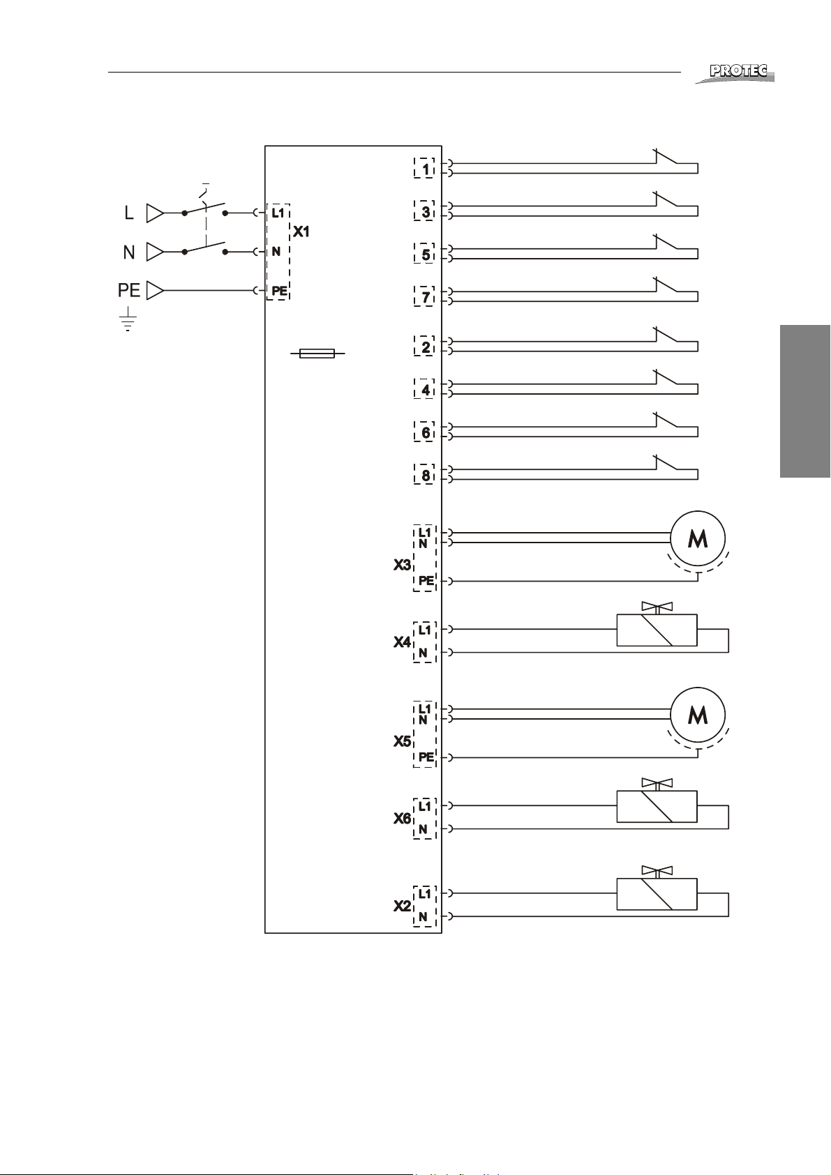
Electric Diagram
R
R
®
Ausschalter
Mainswitch
Erde
Earth
Eingänge
Input
Sicherung Fuse
T/sb 2A/250V
Steuerteil
Electronic
Ausgänge
Output
Niveauschalter F1 - Level switch F1
Niveauschalter F2 - Level switch F2
Niveauschalter F3 - Level switch F3
Notaus - Emergency stop
Niveauschalter D1 - Level switch D1
Niveauschalter D2 - Level switch D2
Niveauschalter D3 - Level switch D3
Notaus - Emergency stop
Fixierer-Pumpe
Fixer pump
W
F
F
I
I
X
X
I
E
E
R
E
R
E
D
N
E
T
V
E
I
L
C
O
K
P
E
L
English
E
R
Magnetventil Fixer
Solenoid valve fixer
Entwickler-Pumpe
Developer pump
Magnetventil Entwickler
Solenoid valve Developer
Magnetventil extern
Solenoid valve external
PROMIX A40
®
15
Page 16
Spare Parts
®
17
10
2
1
45-6
3
20
f
40l
9
e
Wasserstop Notaus
Water-stop, Emergency stop
7-8
22
23
21
30l
16
25l
14
20l
d
10l
15
13
19
Position of Float Switches Standard Mixing Volume 40 Litres
c Auto On float switch (do not change position)
d Half full level - 20 l
Position this float switch in the 10 l position, if the mixing volume is to be set to
20 or 25 litres.
e Full level - 40 l
Position this float switch in the 30 l, 25 l or 20 l position for mixing volumes of
30 litres, 25 litres or 20 litres.
f Water stop, emergency shut-off (do not change position)
18
c
Auto-Ein
Auto-ON
14
11
12
16 PROMIX A40
®
Page 17

Spare Parts
Pos. Order No. Description:
1 0180-5-1000 Controller, complete
2 1180-0-1203 Cable cover
- 2010-0-0009 Fuse 5 x 20 T 2 A / 250 V
- 2004-0-0010 Electrical power cable
- 2028-0-0023 Power switch
3 2006-0-0005 Drain shut-off tap 10 mm
4 1180-0-0106 Flap
5 2031-0-0014 Handle, red
6 2031-0-0015 Handle, blue
7 1180-0-2200 Feed funnel, developer
8 1180-0-2100 Feed funnel, fixer
9 2006-5-0003 Solenoid valve
10 1101-0-0121 Support for solenoid valve
11 0180-1-0800 Centrifugal pump 50 Hz
0180-2-0800 Centrifugal pump 60 Hz
12 2021-0-0009 Ball check valve
13 1180-0-1400 Mixing nozzle
14 1180-0-1600 Level switch
15 1180-0-0204 Support for level switch
16 1180-0-0202 Securing bracket
17 1180-0-0700 Pump tray, complete
18 2030-0-0015 Ring of cellular rubber 280 x 7
19 2030-0-0016 O-ring 22 x 4
20 2019-0-0006 Elbow fitting, reducing
21 1180-0-0211 Inlet pipe
22 1180-0-0900 Level switch (50 mm)
23 1180-0-0215 Support for level switch (50 mm)
- 2018-0-0001 Water inlet tube
®
English
Hose 10 x 2 mm, with fabric inlay
- 2018-0-0008 Colour red
- 2018-0-0009 Colour blue
- 2018-0-0012 Colourless, transparent
Special Accessories
- 1180-0-0103 Rear wall
- 1263-0-0000 Carriage
PROMIX A40
®
17
Page 18
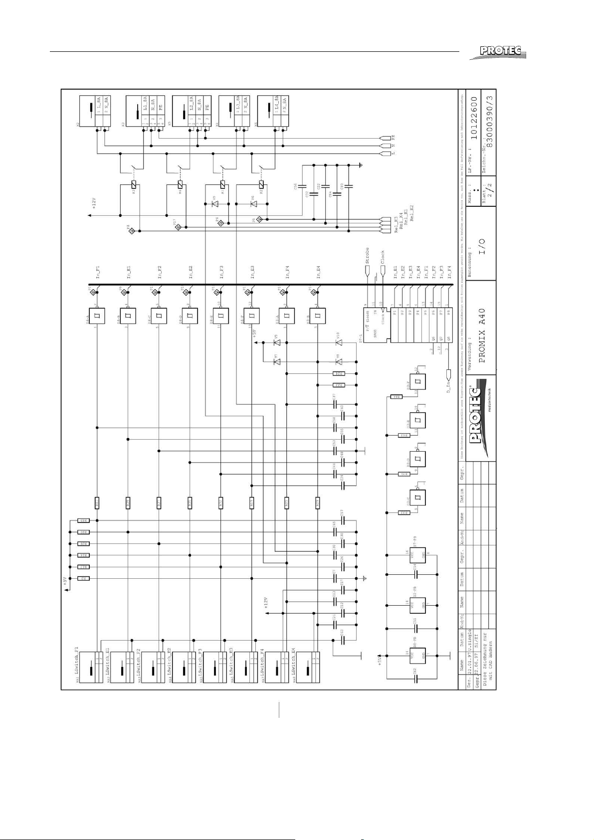
Electric Diagrams
®
18 PROMIX A40
®
Page 19
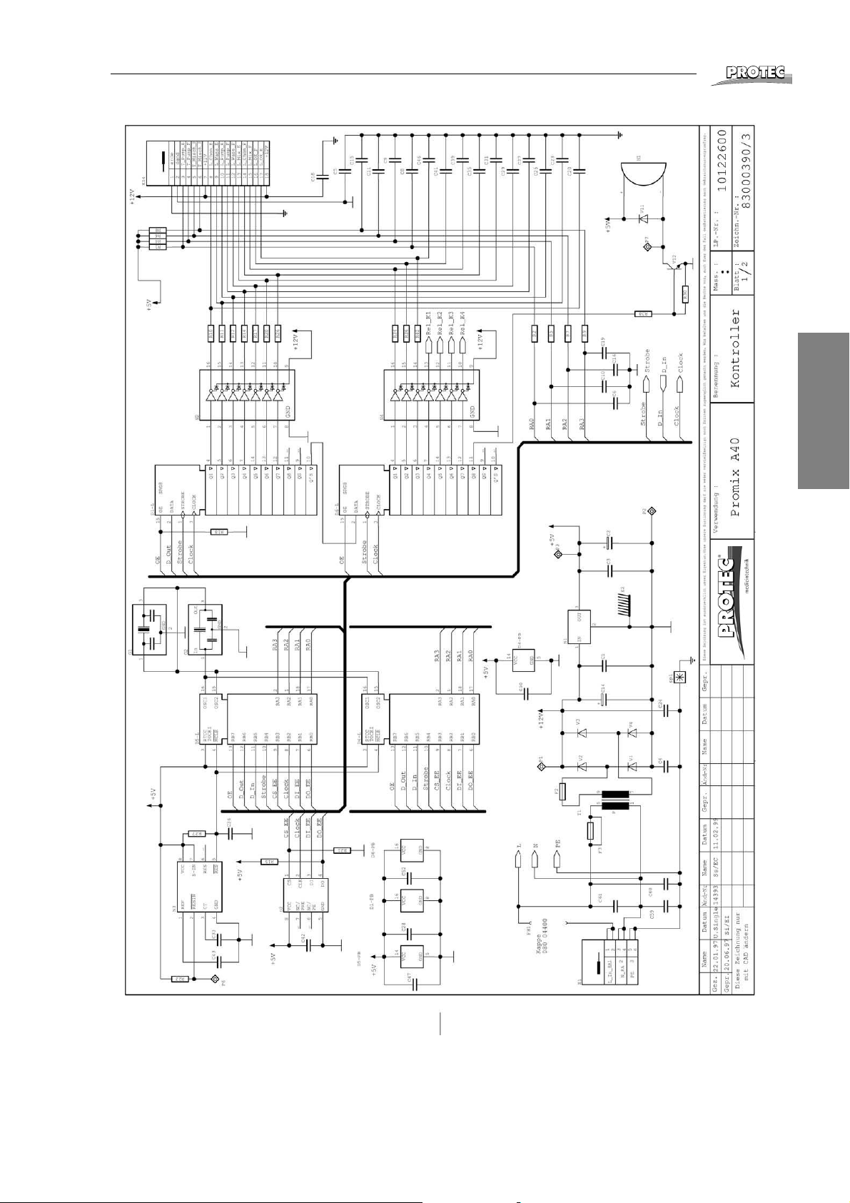
Electric Diagrams
®
English
PROMIX A40
®
19
Page 20
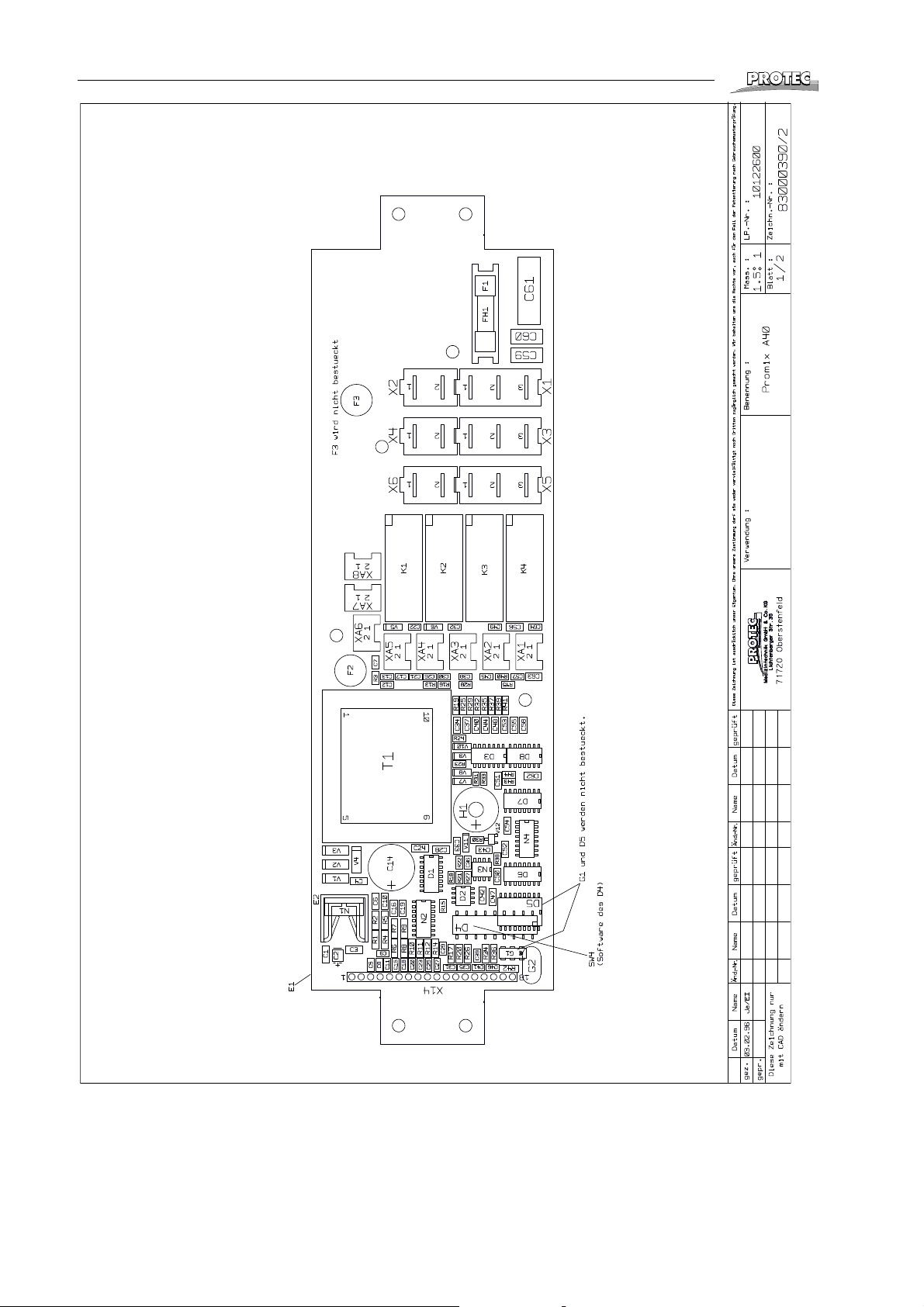
Electric Diagrams
®
20 PROMIX A40
®
 Loading...