

Page 1
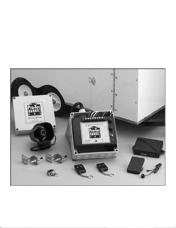
PRO-TEC
SYSTEM ONE
Trailer Security Systems
Photo includes System One Plus pager unit.
“Professional Technology to
Pro-Tec Your Investment”
Page 2

Congratulations
on your purchase of
a state-of-the-art
trailer security system.
This system has been
designed to
provide years of
trouble-free operation.
Page 3

What It Does
The Pro-Tec System One is designed to monitor
and protect your trailer and its contents while at
a race, rest stop, hotel, restaurant, etc. This is
accomplished by door switches and a shock
sensor. Any movement of the trailer or opening
of a door will trigger the alarm. This will cause
the electrical brakes of the trailer to be applied,
running lights will then flash, and the siren will
sound. If you have the optional pager system,
the pager will be notified up to one mile away,
thus alerting you of a potential problem.
This device complies with part 12 of FCC rules.
Operation is subject to the following conditions:
1. This device may not cause harmful interference, and
2. This device must accept any interference
received, including interference that may
cause undesired operation.
The system requires no specific maintenance.
Your remote control is powered by a miniature
12 v. battery, type GP23A, that will last about
a year under normal use. When the battery
weakens, operating range will be reduced and
the LED on the remote light will dim.
This Owner’s Guide should help you get the
most out of your system. Please take the time
to read it thoroughly, prior to using the system.
Page 4

What Is Included
n Control module
n Two transmitters
n 128db Siren
n Brake safety toggle switch
n 3- Pin type door switches
n 3- Door switch brackets
n 1- Seal tite connector
n Mounting screws
n 3- Crimp connectors
n Insurance rebate card
n Warranty card
n 2- Vinyl Decals
Pro-Tec System One Plus Package includes:
All the above plus:
n Pager and base unit
n Manual page button
Page 5

Installing Alarm
n STEP ONE
Deciding on component locations
n SIREN
1. Keep it away from heat sources.
2. Mount it where a thief cannot easily
disconnect it.
3. Point siren down so water does not
collect in it.
n CONTROL UNIT
1. Mount securely inside trailer.
2. The higher the control unit is mounted
in the trailer, the better the transmitter
range will be.
n SWITCHES
1. Mount pin switch.
2. Make sure switch bracket is mounted
to trailer and properly grounded.
n OPTIONAL EQUIPMENT
1. Mount pager antenna outside of trailer.
Page 6

n WIRING
1. Route wiring through trailer so chaffing
and/or pinching will not occur.
2. Solder or crimp connectors are trouble
free if done properly.
3. Insulate all connections with shrink tube
or quality electrical tape.
4. Never twist and tape wires together
without soldering.
n INSTALLATION
1. Installation of 12 volt full size automotive battery, grounded to trailer and
kept charged is needed for proper
operation.
2. Use 20 gauge wire from door switches
to control unit. Use separate wire for
each door and connect to terminal
block marked for that door.
3. Connect 12 gauge wire from trailer
running lights circuit to terminal block.
NOTE:
20 amp load.
4. Connect 12 gauge wire from positive side
of trailer brake circuit to terminal block.
The control unit is able to handle
Page 7

5. Mount brake safety switch in convenient
and secure location. Connect switch to
terminal block.
IMPORTANT: The brake safety switch must
be turned off before trailer is to be towed.
This switch is to prevent accidental trailer
brake activation while towing.
NOTE:
the alarm brake feature will not work.
If this switch is not installed,
6. Connect siren (red wire) to control module
terminal block, connect (black wire) to trailer
ground.
7. Connect 12 gauge wire from negative
battery terminal to control module terminal
block.
8. Connect 12 gauge wire from positive
battery terminal to control terminal block.
NOTE:
When alarm is first powered up
the siren will sound. Press the remote
button #1 twice. First time will silence
alarm, second will shut off alarm. Then
press reset button on alarm box. LED
light should now be off.
For Pro-Tec System One Plus package:
9. Connect pager to control unit.
Follow Pager Instructions.
Page 8

Testing Alarm
Close ALL doors and press button #1 once.
1. Trailer lights should flash once.
2. Alarm in now armed.
3. Open side door
a. Running lights are flashing.
b. Siren is sounding.
c. Brakes are engaged.
d. Optional Pager will sound.*
e. Press Button #1 once to silence siren.
Note: Alarm is still armed.
f. Press button #1 again to disarm alarm.
g. Trailer lights will flash at least twice.
Repeat above sequence to test all doors.
4.Setting sensitivity on Shock Sensor
a. Turn set screw to halfway point.
b. Place 2X4s a few feet in front of the tow
vehicle wheels and tow trailer over 2X4s.
Further adjustment might be necessary according
to your environment.
*Pro-Tec System One Plus only.
Page 9

Nuisance Prevention Circuitry
Your system has Nuisance Prevention Circuitry
(NPC). It prevents annoying repetitive trigger
sequences due to faulty door pin switches or
environmental conditions such as thunder,
jackhammers, airport noise, etc.
Here’s how it works:
Lets say the alarm triggers three times. Each time
the same sensor or switch is triggering the alarm.
The three triggers are within 60 minutes of each
other. NPC will interpret this pattern of triggers as
false alarms. After the third trigger, NPC ignores
or bypasses that sensor or switch (along with any
other sensors or switches sharing the same zone).
If the bypassed sensor tries to trigger the system
while it is being bypassed, the 60-minute bypass
period will start over. This ensures that a sensor
that continuously triggers will remain bypassed.
Doors are covered by NPC differently: If the alarm
is triggered by an open door for three full cycles
(one and one half minutes), the doors will be
bypassed until the trigger ceases.
NOTE:
not reset this function! The only ways to reset
a bypassed zone are for it to not trigger for
60 minutes or disconnect power to the control
module and re-connect power.
Arming and disarming the system does
Page 10

Using Your System
ARMING
You can turn on, or arm, the system by pressing
button #1 of your transmitter. When the system is
armed, you will see the running lights flash once.
DISARMING
1. If siren is not sounding
Press button #1 once.
Running lights will flash at least twice.
Trailer is now disarmed and safe to enter.
2. If siren is sounding
Press button #1 once.
This will silence the siren and
stop the running lights flashing.
Note. Trailer alarm is still armed.
Press button #1 again, this will flash
the running lights at least two times.
Trailer is now disarmed and safe to enter.
Page 11

High Security Disarm
Your system includes a High Security Disarm
feature. During the trigger sequence, using the
transmitter to disarm the system will only stop
the trigger sequence (the alarm will stop and the
running lights will stop flashing). However, the
system will remain armed. This is extremely useful if
you must stop the system from sounding but are
unable to check the trailer visually. The trigger will
stop but the trailer will remain armed.
Optional Pro-Tec System One Plus
Pager will notify you of alarm up to 1 mile away.
There is also a pager key pad that can be used
to notify pager without having alarm trigger.
IMPORTANT: The brake safety switch must be
turned off before trailer is to be towed. This
switch is to prevent accidental trailer brake
activation while towing.
NOTE:
alarm brake feature will not work.
If this switch is not installed, the
Page 12

Troubleshooting
Shock sensor doesn’t trigger alarm
Has the NPC system been triggered? To check
this press reset to clear the NPC memory and
then retest the shock sensor.
LED indicator flashing sequence
This feature is used to tell you if and what trigger
point was triggered while you were away. It also
helps determine where to look if you are
experiencing false alarms.
1. Steady Flashing .................System armed
2. No Flashing........................System disarmed
3. One Flash ..........................Generator door
4. Two Flashes .......................Shock sensor
5. Three Flashes ....................Side or rear door
To reset LED indicator
Disarm alarm. Then press reset button on control
module. LED should shut off.
Page 13

Wiring Diagram
Page 14

Warranty
TOMAL Systems, LLC promises to the ORIGINAL
PURCHASER to repair or replace (with a comparable model) any electronic control module
which proves to be defective in workmanship
or material under normal use for life. If warranty
service is necessary you must have a clean copy
of your sales receipt.
This warranty is void if the product has been
damaged by accident, unreasonable use,
neglect, improper service or other causes not
arising out of defects in materials or construction.
This warranty is nontransferable and does not
apply to any unit that has been modified or used
in a manner contrary to its intended purpose
and does not cover batteries.
The unit in question must be returned to the manufacturer, postage prepaid. This warranty does
not cover labor costs for the removal, diagnosis,
troubleshooting, removal or installation of the unit.
These systems are a deterrent against possible
theft. TOMAL Systems LLC is not offering a
guarantee or insuring against the theft of the
trailer or its contents, and disclaims any liability
for the theft of the trailer and/or its contents.
TOMAL Systems LLC does not authorize any
person to create for it any other obligation or
liability in connection with the security system.
Page 15

“TO THE MAXIMUM EXTENT ALLOWED BY LAW,
ANY AND ALL WARRANTIES ARE EXCLUDED BY
THE MANUFACTURER AND EACH ENTITY
PARTICIPATING IN THE STREAM OF COMMERCE
THEREWITH. THIS EXCLUSION INCLUDES BUT IS
NOT LIMITED TO, THE EXCLUSION OF ANY AND
ALL WARRANTY OF MERCHANTABILITY AND/OR
ANY AND ALL WARRANTY OF FITNESS FOR
PARTICULAR PURPOSE AND/OR ANY AND ALL
WARRANTY OF NON-INFRINGEMENT OF PATENTS
IN THE UNITED STATE OF AMERICA AND/OR
ABROAD. NEITHER THE MANUFACTURER OR
ANY ENTITIES CONNECTED THEREWITH SHALL
BE RESPONSIBLE OR LIABLE FOR ANY DAMAGES
WHATSOEVER, INCLUDING BUT NOT LIMITED TO,
AND CONSEQUENTIAL DAMAGES, INCIDENTAL
DAMAGES, DAMAGES FOR LOSS OF TIME,
LOSS OF EARNINGS, COMMERCIAL LOSS, LOSS
OF ECONOMIC OPPORTUNITY AND THE LIKE.
NOTWITHSTANDING, THE ABOVE MANUFACTURER DOES OFFER A LIMITED WARRANTY TO
REPLACE OR REPAIR THE CONTROL MODULE
AS DESCRIBED ABOVE”.
Important Note
A product’s warranty is automatically void if its
serial number is defaced, missing, or altered, or if
the black box is separated from outer box or
entered.
Page 16

Serial #
Date Installed / /
Purchased From:
TOMAL
SYSTEMS,LLC
Manufacturers of Pro-Tec Systems
888-741-1004
252-633-4584
252-636-5704 Fax
 Loading...