

Page 1
RLX2-IHx Series
802.11a, b, g, n
Industrial Hotspots
802.11abg, RLX2-IHW
802.11abgn, Fast, RLX2-IHNF
802.11g, High Power, RLX2-IHG
802.11a, High Power, RLX2-IHA
802.11abgn, Weatherproof IP66/67, RLX2-IHNF-W/WC
June 15, 2015
USER MANUAL
Page 2

Your Feedback Please
We always want you to feel that you made the right decision to use our products. If you have suggestions, comments,
compliments or complaints about our products, documentation, or support, please write or call us.
How to Contact Us
ProSoft Technology
5201 Truxtun Ave., 3rd Floor
Bakersfield, CA 93309
+1 (661) 716-5100
+1 (661) 716-5101 (Fax)
www.prosoft-technology.com
support@prosoft-technology.com
Copyright © 2015 ProSoft Technology, Inc. All rights reserved.
RLX2 Series User Manual
June 15, 2015
ProSoft Technology ®, ProLinx ®, inRAx ®, ProTalk ®, and RadioLinx ® are Registered Trademarks of ProSoft Technology, Inc.
All other brand or product names are or may be trademarks of, and are used to identify products and services of, their
respective owners.
In an effort to conserve paper, ProSoft Technology no longer includes printed manuals with our product shipments. User
Manuals, Datasheets, Sample Ladder Files, and Configuration Files are provided on the enclosed DVD, and are available at
no charge from our web site: http://www.prosoft-technology.com
Content Disclaimer
This documentation is not intended as a substitute for and is not to be used for determining suitability or reliability of
these products for specific user applications. It is the duty of any such user or integrator to perform the appropriate and
complete risk analysis, evaluation and testing of the products with respect to the relevant specific application or use
thereof. Neither ProSoft Technology nor any of its affiliates or subsidiaries shall be responsible or liable for misuse of the
information contained herein. Information in this document including illustrations, specifications and dimensions may
contain technical inaccuracies or typographical errors. ProSoft Technology makes no warranty or representation as to its
accuracy and assumes no liability for and reserves the right to correct such inaccuracies or errors at any time without
notice. If you have any suggestions for improvements or amendments or have found errors in this publication, please
notify us.
No part of this document may be reproduced in any form or by any means, electronic or mechanical, including
photocopying, without express written permission of ProSoft Technology. All pertinent state, regional, and local safety
regulations must be observed when installing and using this product. For reasons of safety and to help ensure compliance
with documented system data, only the manufacturer should perform repairs to components. When devices are used for
applications with technical safety requirements, the relevant instructions must be followed. Failure to use ProSoft
Technology software or approved software with our hardware products may result in injury, harm, or improper operating
results. Failure to observe this information can result in injury or equipment damage.
© 2015 ProSoft Technology, Inc. All rights reserved.
Page 3

Important Safety Information
The following Information and warnings pertaining to the radio module must be heeded:
WARNING – EXPLOSION HAZARD – DO NOT REPLACE ANTENNAS UNLESS POWER HAS BEEN SWITCHED OFF OR THE
AREA IS KNOWN TO BE NON-HAZARDOUS.
"THIS DEVICE CONTAINS ONE OF THE FOLLOWING TRANSMITTER MODULES:
FCC ID: OQ7IHG, RYK-WMIA199NI, NKRDCMA82, SWX-XR5
PLEASE SEE FCC ID LABEL ON BACK OF DEVICE."
"THIS DEVICE USES AN INTERNAL COMPACT FLASH RADIO MODULE AS THE PRIMARY RADIO
COMPONENT. THE COMPACT FLASH RADIO MODULE DOES NOT HAVE AN FCC ID LABEL. THE
COMPACT FLASH RADIO MODULE HAS NO USER SERVICEABLE PARTS."
"THIS DEVICE COMPLIES WITH PART 15 OF THE FCC RULES. OPERATION IS SUBJECT TO THE
FOLLOWING TWO CONDITIONS: (1) THIS DEVICE MAY NOT CAUSE HARMFUL INTERFERENCE, AND
(2) THIS DEVICE MUST ACCEPT ANY INTERFERENCE RECEIVED, INCLUDING INTERFERENCE THAT MAY
CAUSE UNDESIRED OPERATION."
"CHANGES OR MODIFICATIONS NOT EXPRESSLY APPROVED BY THE PARTY RESPONSIBLE FOR
COMPLIANCE COULD VOID THE USER’s AUTHORITY TO OPERATE THE EQUIPMENT."
“THIS DEVICE IS CONFIGURED FOR OPERATION IN THE USA DURING MANUFACTURING. THESE
CONFIGURATION CONTROLS ARE NOT PRESENT IN THE SOFTWARE WITH WHICH THE UNIT IS
SHIPPED; THEREFORE THE END USER CANNOT CHANGE THE MAX POWER SETTINGS OR THE
COUNTRY/REGION. THE MODELS SOLD & SHIPPED WITHIN THE U.S. ARE IDENTIFIED WITHIN THE
MODEL NUMBER WITH –A AS PART OF THE IDENTIFIER.”
Industry Canada Requirements:
"THIS DEVICE HAS BEEN DESIGNED TO OPERATE WITH AN ANTENNA HAVING A MAXIMUM GAIN OF
24 dB. AN ANTENNA HAVING A HIGHER GAIN IS STRICTLY PROHIBITED PER REGULATIONS OF
INDUSTRY CANADA. THE REQUIRED ANTENNA IMPEDANCE IS 50 OHMS."
"TO REDUCE POTENTIAL RADIO INTERFERENCE TO OTHER USERS, THE ANTENNA TYPE AND ITS GAIN
SHOULD BE CHOSEN SUCH THAT THE EQUIVALENT ISOTROPICALLY RADIATED POWER (EIRP) IS NOT
MORE THAN THAT REQUIRED FOR SUCCESSFUL COMMUNICATION."
"THE INSTALLER OF THIS RADIO EQUIPMENT MUST INSURE THAT THE ANTENNA IS LOCATED OR
POINTED SUCH THAT IT DOES NOT EMIT RF FIELD IN EXCESS OF HEALTH CANADA LIMITS FOR THE
GENERAL POPULATION; CONSULT SAFETY CODE 6, OBTAINABLE FROM HEALTH CANADA."
Page 4

RLX2-IHNF, RLX2-IHA, RLX2-IHG, RLX2-IHW
1. This equipment is Suitable For Use in Class I, Division2, Groups A, B, C, D or Non-Hazardous
Location Only.
2. WARNING – EXPLOSION HAZARD – Substitution of Any Components May Impair Suitability
for Class I, Division 2.
3. WARNING – EXPLOSION HAZARD – Do not disconnect equipment unless power has been
removed or the area is known to be non-hazardous.
4. The unit is to be connected only to PoE networks without routing to the outside plant.
5. WARNING – EXPLOSION HAZARD – The SIM Card/Personality Module connection is for initial
setup and maintenance only. Do not use, connect, or disconnect unless area is known to be
non-hazardous. Connection or disconnection in an explosive atmosphere could result in
explosion.
6. Device must be powered by a Class 2 Power Source.
7. Device is an open-type and is to be installed in an enclosure suitable for the environment.
RLX2-IHNF-W
1. WARNING – EXPLOSION HAZARD – DO NOT USE IN CID2 HAZARDOUS LOCATIONS.
2. WARNING – DO NOT CONNECT OR DISCONNECT WHEN ENERGIZED.
3. This unit is to be connected only to PoE networks without routing to an outside plant.
4. Device must be powered by a Class 2 Power Source.
5. Make sure proper grounding is secured.
6. Unit does not comply to the cable assy requirements of ISA 12.12.01 but does comply with
the ATEX standards IEC60079-0 & IEC60079-15. In ATEX environments, do not
connect/disconnect unless area is known to be non-hazardous.
RLX2-IHNF-WC
1. SUITABLE FOR USE IN CLASS I, Division 2, GROUPS A, B, C, and D HAZARDOUS LOCATIONS, or
NON-HAZARDOUS LOCATIONS ONLY.
2. WARNING – EXPLOSION HAZARD – SUBSTITUTION OF ANY COMPONENTS MAY IMPAIR
SUITABILTY FOR CLASS I, DIVISION 2.
3. WARNING – EXPLOSION HAZARD – DO NOT DISCONNECT EQUIPMENT UNLESS POWER HAS
BEEN REMOVED OR THE AREA IS KNOWN TO BE NON-HAZARDOUS.
4. This unit is to be connected only to PoE networks without routing to the outside plant.
Page 5

ProSoft Part Number
Max Gain and Type
A2403NBH-OC
3 dBi Omni N-BH jack whipless 2.4GHz
A2404NBHW-OC
4 dBi Omni N BH jack low profile 2.4GHz
A2404NJ-OC
4 dBi Omni N jack collinear with mounting hardware 2.4GHz
A2405S-OA
5 dBi Omni RP-SMA articulating 2.4GHz
A2405S-OM
5 dBi Omni RP-SMA straight w/magnetic base 2.4GHz
A2405S-OS
5 dBi Omni RP-SMA straight 2.4GHz
A2406NJ-OC
6 dBi Omni N jack collinear with mounting hardware 2.4GHz
A2406NJ-OCD
6dBi Omni N jack heavy duty collinear with mounting hardware 2.4GHz
A2406S3-DP
6dBi Panel RP-SMA MIMO antenna with 3 foot pigtail 2.4GHz
A2408NJ-DP
8 dBi Directional patch panel N jack with mounting hardware 2.4GHz
A2408NJ-OC
8 dBi Omni N jack collinear with mounting hardware 2.4GHz
A2409NJ-OCD
9 dBi Omni N jack heavy duty collinear with mounting hardware 2.4GHz
A2410NJ-DY
10 dBi Directional N jack Yagi with mounting hardware 2.4GHz
A2410NJ-OCM
10 dBi Omni N jack collinear for marine environment, 2.4GHz
5. The equipment shall be properly grounded with the external ground screw provided
connected to building ground as well as the antenna coaxial screen of the connector shall be
grounded.
6. Device must be powered by a Class 2 Power Source.
7. The common or earth side of the circuit side is connected to the screen of the coaxial cable
and to all accessible parts and circuits.
8. Shall be installed in Restricted Access Location Only.
9. Antennas are to be installed in accordance with Control Drawing 06/2514. You can find the
Control Drawing in the Antenna section of this manual.
Recommended Antennas
ProSoft offers a variety of Antennas and Cables for use with your RadioLinx device. The following is
a sample of available antennas.
For a complete list and description, please visit our website: http://www.prosoft-
technology.com/Products/Industrial-Wireless - Antennas and Accessories.
Page 6

A2412NJ3-DP
12dBi Panel N-Jack MIMO antenna 2.4GHz
A2413NJ-DP
13 dBi Directional patch panel N jack with mounting hardware 2.4GHz
A2415NJ-DY
15 dBi Directional N jack Yagi with mounting hardware 2.4GHz
A2416NJ-DS
16 dBi Directional 120 degree sector N jack with mounting hardware 2.4GHz
A2419NJ-DB
19 dBi Directional N jack parabolic with mounting hardware 2.4GHz
A2419NJ-DP
19 dBi patch panel N jack with mounting hardware 2.4GHz
A2424NJ-DB
24 dBi Directional N jack parabolic with mounting hardware 2.4GHz
A2502S-OA
2dBi omni RP-SMA articulating 2.4/5GHz
A2506NJ-OC
6/8dBi omni N jack collinear with mounting hardware 2.4/5GHz
A5003S-OBH
3dBi Omni RP-SMA bulkhead mount with 5' LMR195 pigtail 5GHz
A5006NJ-OC
6dBi omni N jack collinear with mounting hardware 5GHz
A5007S3-DP
7dBi Panel RP-SMA MIMO antenna with 3 foot pigtail 5GHz
A5009NJ-OC
9dBi omni N jack collinear with mounting hardware 5GHz
A5017NJ3-DP
17dBi Panel N-Jack MIMO antenna 5GHz
A5019NJ-DP
19dBi directional N jack panel with mounting hardware 5GHz
A5024NJ-DP
24dBi directional N jack panel with mounting hardware 5GHz
A5812NJ-OC
12dBi omni N jack collinear with mounting hardware 5.8GHz
A5829NJ-DB
29dBi directional N jack parabolic with mounting hardware 5.8GHz
A2503S3-O
3/4dBi Omni RP-SMA MIMO antenna with 3 foot pigtail 2.4/5GHz
A2503S6-O
3/4dBi Omni RP-SMA Dual MIMO antenna with 3 foot pigtail 2.4/5GHz
A2506NJ3-O
6dBi Omni N-Jack Single MIMO antenna with 3 foot pigtail 2.4/5GHz
An adapter may be needed for some of the listed antennas to operate with certain radios
Antenna Spacing Requirements for User Safety
It is important to keep the radio's antenna a safe distance from the user. To meet the requirements of FCC part 2.1091 for
radio frequency radiation exposure, this radio must be used in such a way as to guarantee at least 20 cm between the
antenna and users. Greater distances are required for high-gain antennas. The FCC requires a minimum distance of 1 mW
*cm2 power density from the user (or 20 cm, whichever is greater).
If a specific application requires proximity of less than 20 cm, the application must be approved through the FCC for
compliance to part 2.1093.
Page 7

Contents
YOUR FEEDBACK PLEASE .......................................................................................................................................... 2
HOW TO CONTACT US ............................................................................................................................................ 2
CONTENT DISCLAIMER............................................................................................................................................. 2
IMPORTANT SAFETY INFORMATION ............................................................................................................................ 3
Industry Canada Requirements: .................................................................................................................... 3
RLX2-IHNF, RLX2-IHA, RLX2-IHG, RLX2-IHW.................................................................................................. 4
RLX2-IHNF-W................................................................................................................................................. 4
RLX2-IHNF-WC .............................................................................................................................................. 4
Recommended Antennas .............................................................................................................................. 5
Antenna Spacing Requirements for User Safety ........................................................................................................ 6
START HERE .................................................................................................................................................. 13
ABOUT THIS MANUAL ........................................................................................................................................... 13
About the RadioLinx® RLX2 Industrial Hotspot™ Products .......................................................................... 14
General Features ...................................................................................................................................................... 14
PACKAGE CONTENTS ............................................................................................................................................. 19
Standard Content RLX2-IHNF-W ................................................................................................................. 19
RLX2-IHNF-W Cables ................................................................................................................................................ 19
Standard Contents (RLX2-IHNF-WC) ........................................................................................................... 20
Standard Contents (All other radios) ........................................................................................................... 20
Industrial Hotspot Bench Test Kit (RLX-IHBTK) ............................................................................................ 21
Personality Module ..................................................................................................................................... 21
THE RADIOLINX INDUSTRIAL HOTSPOT BROWSER CONFIGURATION TOOL ........................................................................ 22
System Requirements .................................................................................................................................. 22
Installation from DVD ................................................................................................................................. 22
Installation from Download File .................................................................................................................. 25
RLX2 QUICK SETUP ........................................................................................................................................ 27
SETUP MASTER RADIO .......................................................................................................................................... 28
For RLX2-IHNF-W Radios ............................................................................................................................. 28
For RLX2-IHNF-WC Radios ........................................................................................................................... 30
For All Other Radios .................................................................................................................................... 35
SETUP REPEATER RADIO ........................................................................................................................................ 42
SETUP CLIENT RADIO ............................................................................................................................................ 44
INSTALL REPLACEMENT RADIO USING PERSONALITY MODULE ....................................................................................... 46
PLANNING THE NETWORK ...................................................................................................................................... 47
Installation Questions ................................................................................................................................. 49
Planning the Physical Installation ............................................................................................................... 49
ProSoft Wireless Designer ........................................................................................................................... 49
Functional Specifications: ......................................................................................................................................... 52
Personality Module Configuration Restoration ........................................................................................................ 53
INSTALLING THE RADIOS ............................................................................................................................... 55
CONNECTING ANTENNAS ....................................................................................................................................... 57
Page 8

TEST THE NETWORK INSTALLATION PLAN ................................................................................................................... 57
DIAGNOSTICS AND TROUBLESHOOTING ....................................................................................................... 59
DIAGNOSTICS ....................................................................................................................................................... 60
CHECK THE ETHERNET CABLE ................................................................................................................................... 61
LED DISPLAY ........................................................................................................................................................ 62
RETRIEVE THE DEFAULT PASSWORD .......................................................................................................................... 63
RLX2-IHNF-W and RLX2-IHNF-WC Reset ...................................................................................................... 63
Resetting All Other Radios ........................................................................................................................... 64
TROUBLESHOOT IH BROWSER ERROR MESSAGES ......................................................................................................... 65
TROUBLESHOOT MISSING RADIOS ............................................................................................................................ 65
IMPROVE SIGNAL QUALITY ...................................................................................................................................... 66
DETAILED RADIO CONFIGURATION / DIAGNOSTICS ...................................................................................... 67
READ-ONLY FIELDS................................................................................................................................................ 68
CONFIGURATION HELP ........................................................................................................................................... 68
RADIO STATUS ...................................................................................................................................................... 72
Available Parents ......................................................................................................................................... 73
Address Table ............................................................................................................................................... 75
Port Status ................................................................................................................................................... 76
RADIO NETWORK SETTINGS .................................................................................................................................... 78
Parent Link Settings ..................................................................................................................................... 82
Prioritized Parent Selection ...................................................................................................................................... 85
IGMP Settings .............................................................................................................................................. 88
VLAN Settings............................................................................................................................................... 88
QoS Settings ................................................................................................................................................. 90
Rapid Spanning Tree Functionality .............................................................................................................. 92
Spanning Tree Settings ................................................................................................................................ 95
Advanced Settings........................................................................................................................................ 97
Roam Control ............................................................................................................................................. 102
SECURITY SETTINGS ............................................................................................................................................. 105
Encryption Type ......................................................................................................................................... 108
WPA Phrase ............................................................................................................................................... 108
Enterprise Mode Settings ........................................................................................................................... 109
Certificate Management ............................................................................................................................ 110
Configuring the RLX2 Repeaters with Certificates .................................................................................................. 111
WEP Key ..................................................................................................................................................... 112
MAC Filter .................................................................................................................................................. 114
Hide Network SSID ..................................................................................................................................... 114
RADIO ACCESS SETTINGS ...................................................................................................................................... 115
SNMP Agent Settings ................................................................................................................................. 117
Serial Settings ............................................................................................................................................ 118
Change Password ....................................................................................................................................... 121
APPLY CHANGES ................................................................................................................................................. 122
CANCEL CHANGES ............................................................................................................................................... 122
FACTORY DEFAULTS ............................................................................................................................................. 122
Page 9

RLX2-IHNF DFS SUPPORT .................................................................................................................................. 123
Master Radio Operations .......................................................................................................................... 123
DFS Auto Select ......................................................................................................................................... 124
RADIOLINX INDUSTRIAL HOTSPOT BROWSER ............................................................................................. 125
PRIMARY RADIO FUNCTIONS ................................................................................................................................ 126
FILE MENU ....................................................................................................................................................... 127
Scan Setup ................................................................................................................................................. 127
Scan ........................................................................................................................................................... 128
Clear .......................................................................................................................................................... 128
Import ....................................................................................................................................................... 128
Export ........................................................................................................................................................ 128
Freeze ........................................................................................................................................................ 128
Print........................................................................................................................................................... 128
Print Preview ............................................................................................................................................. 129
Print Setup ................................................................................................................................................. 129
Exit ............................................................................................................................................................ 129
OPERATIONS MENU ........................................................................................................................................... 129
Connect ..................................................................................................................................................... 130
Assign IP .................................................................................................................................................... 131
Update Firmware ...................................................................................................................................... 132
Ping Device ................................................................................................................................................ 132
Ping Options Dialog Box ......................................................................................................................................... 133
DIALOGS MENU ................................................................................................................................................. 134
Wireless Clients ......................................................................................................................................... 134
Ethernet Nodes ......................................................................................................................................... 135
Scan List .................................................................................................................................................... 136
802.11 Access Point Detector ................................................................................................................................. 137
Port Table .................................................................................................................................................. 137
All 4 Dialogs .............................................................................................................................................. 138
Close All ..................................................................................................................................................... 138
Event Log ................................................................................................................................................... 138
Event Filter ............................................................................................................................................................. 139
Properties .................................................................................................................................................. 139
VIEW MENU ..................................................................................................................................................... 140
Toolbar ...................................................................................................................................................... 140
Status Bar .................................................................................................................................................. 141
List View .................................................................................................................................................... 141
Topology View ........................................................................................................................................... 145
Topology View Key ................................................................................................................................................. 145
Zoom In ..................................................................................................................................................... 147
Zoom Out .................................................................................................................................................. 147
Zoom to Fit ................................................................................................................................................ 148
Show Ping Stations .................................................................................................................................... 148
Show Parents - All ..................................................................................................................................... 149
Show Parents - One ................................................................................................................................... 149
Page 10

Print Area ................................................................................................................................................... 149
Reset Columns ............................................................................................................................................ 150
Select Columns ........................................................................................................................................... 150
HELP MENU ....................................................................................................................................................... 150
Help Topics ................................................................................................................................................. 151
About RLX IH Browser ................................................................................................................................ 152
RLX2 VIRTUAL LAN (VLAN) FUNCTIONALITY ................................................................................................ 153
TRANSPARENT SUPPORT OF VLAN TAGS (802.1Q) .................................................................................................. 153
PORT/RADIO-BASED VLAN TAGGING WITH MANAGED SWITCHES ............................................................................... 154
PORT/RADIO-BASED VLAN TAGGING WITHOUT MANAGED SWITCHES .......................................................................... 155
REFERENCE.................................................................................................................................................. 157
PRODUCT OVERVIEW ........................................................................................................................................... 157
COMPATIBILITY WITH PROSOFT RLXIB SERIES RADIOS ............................................................................................... 159
DIMENSIONAL DRAWINGS .................................................................................................................................... 161
MASTER CHANNEL-FREQUENCY TABLE .................................................................................................................... 163
FCC EMISSION REGULATIONS ................................................................................................................................ 165
2.4 GHz Band, Point-To-Multipoint ............................................................................................................ 165
2.4 GHz Band, Point-To-Point .................................................................................................................... 165
5 GHz Bands, Point-To-Multipoint ............................................................................................................. 166
5 GHz Bands, Point-To-Point ...................................................................................................................... 166
RADIO HARDWARE .............................................................................................................................................. 167
Radio Power Requirements (RLX2-IHNF-W) ............................................................................................... 167
Ethernet Cable Specifications..................................................................................................................... 171
Ethernet Cable Configuration (RLX2-IHNF-W) ........................................................................................... 171
Ethernet Cable Configuration (all other radios) ......................................................................................... 173
RLX2-IHA DETAILED SPECIFICATIONS ..................................................................................................................... 174
Agency Approvals & Certifications ......................................................................................................................... 175
RLX2-IHG DETAILED SPECIFICATIONS ..................................................................................................................... 175
Agency Approvals & Certifications ......................................................................................................................... 176
RLX2-IHNF, -W, -WC DETAILED SPECIFICATIONS .................................................................................................... 176
Agency Approvals & Certifications ......................................................................................................................... 178
RLX2-IHW DETAILED SPECIFICATIONS .................................................................................................................... 179
Agency Approvals & Certifications ......................................................................................................................... 180
ANTENNA CONFIGURATION ........................................................................................................................ 181
ANTENNAS ......................................................................................................................................................... 181
Control Drawing ......................................................................................................................................... 182
Antenna Pattern ........................................................................................................................................ 183
Antenna Gain ............................................................................................................................................. 184
Antenna Polarity ........................................................................................................................................ 184
Whip Antennas .......................................................................................................................................... 185
Collinear Array Antennas ........................................................................................................................... 185
Yagi Array Antenna .................................................................................................................................... 186
Parabolic Reflector Antennas ..................................................................................................................... 186
RLX2 Approved Antennas ........................................................................................................................... 187
Page 11

Approved Antennas in Europe/CE .......................................................................................................................... 188
Approved Antennas in Mexico ............................................................................................................................... 189
Approved Antennas with Power Amp .................................................................................................................... 189
Antenna Location, Spacing, and Mounting ............................................................................................... 190
SUPPORT, SERVICE & WARRANTY ............................................................................................................... 191
CONTACTING TECHNICAL SUPPORT ........................................................................................................................ 191
Warranty Information ............................................................................................................................... 192
GLOSSARY OF TERMS .................................................................................................................................. 193
INDEX ......................................................................................................................................................... 209
Page 12

Page 13

RLX2 Industrial Hotspot Series
Model
Standards
Maximum Output Power
RLX2-IHA
IEEE 802.11a
24 dBm (250 mW)
RLX2-IHG
IEEE 802.11b/g
24 dBm (250 mW)
RLX2-IHNF
IEEE 802.11a/b/g/n
17 dBm (50 mW)
RLX2-IHNF-W
IEEE 802.11a/b/g/n
17 dBm (50 mW)
RLX2-IHNF-WC
IEEE 802.11a/b/g/n
17 dBm (50mW)
RLX2-IHW
IEEE 802.11a/b/g
20 dBm (200 mW)
S T A R T H E R E
For most applications, the installation and configuration steps described in the following
topics will work without additional programming. ProSoft Technology strongly
recommends the completion of the steps in this chapter before developing a custom
application.
About This Manual
This manual covers the entire RadioLinx® RLX2 Industrial Hotspot™ series of radio
products. There are five products available in this product line:
Except for different operating frequencies and output power levels, these radios all
operate in a similar fashion. Different models operating on common frequencies can
communicate with each other. Furthermore, most RLX2 series radios (except RLX2-IHNF)
can communicate with ProSoft Technology’s legacy RLXIB series of radios. Details on the
specific differences between the RLX2 and RLXIB series products can be found in the
Compatibility with ProSoft RLXIB Series Radios section on page 159.
ProSoft Technology, Inc. Page 13 of 212
June 15, 2015
Page 14

RLX2 Industrial Hotspot Series
Power
While booting up
When fully operational
RF Transmit
While transmitting over wireless
RF Receive
While receiving over wireless
Serial
When a serial cable is attached
Ethernet
When Ethernet data is being
transferred
Net
Alternates red and green if SD card
with new configuration inserted
Mod
Alternates red and green if SD card
with new configuration inserted
Signal Strength LEDs: SD card inserted
Alternates green and amber if SD
card with new configuration inserted
Signal Strength LEDs: running in Client or
Repeater Modes
No Signal
About the RadioLinx® RLX2 Industrial Hotspot™ Products
General Features
The RadioLinx® 802.11 Industrial Hotspots™ are high-speed wireless Ethernet radios,
with Power over Ethernet (PoE) and Serial Encapsulation. All radios operate at speeds
up to 54 Mbps, and the RLX2-IHNF operates at speeds up to 300 Mbps. Designed for
industrial installations, the RLX2 series offer many features including hazardous location
certifications, IGMP Snooping, OFDM for noise immunity, repeater mode to extend
range, QoS, VLANs, RADIUS Server, automatic parent selection for self-healing, OPC
server diagnostics, extended temperature, high vibration/shock and DIN-rail mounting.
LED Indicators
All radios have LED indicators on the front panel that indicate the status of the radio
while booting up and during operation. The LED states are summarized in the following
table:
Page 14 of 212 ProSoft Technology, Inc.
June 15, 2015
Page 15
RLX2 Industrial Hotspot Series
Radio linked, Poor Signal
Radio linked, Fair Signal
Radio linked, Good Signal
Signal Strength LEDs: running in Master
Mode
No radios linked
One or more radios linked
(right LED blinking).
DFS Channel Availability Check
in progress (all LEDs blinking Amber)
See section 0 for further details regarding the LED display for various conditions.
Antenna Ports
Each RLX2 series radio has active antenna connectors on the top as shown below:
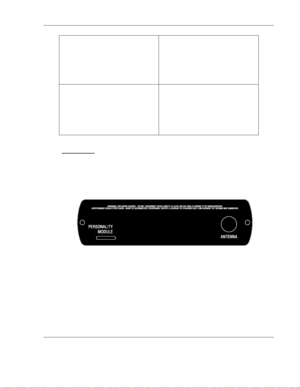
RLX2-IHA
RLX2-IHG
These radios have a single active antenna port:
ProSoft Technology, Inc. Page 15 of 212
June 15, 2015
Page 16
RLX2 Industrial Hotspot Series
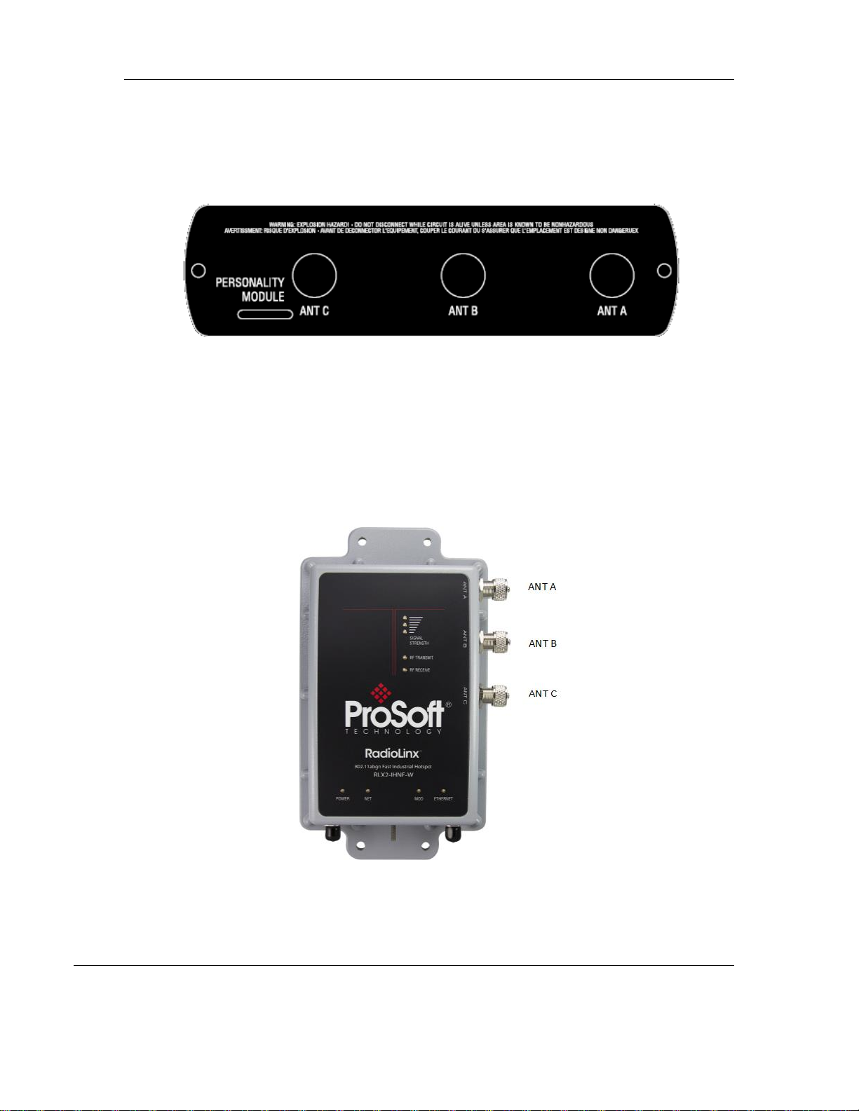
RLX2-IHNF
This radio has three active antenna ports:
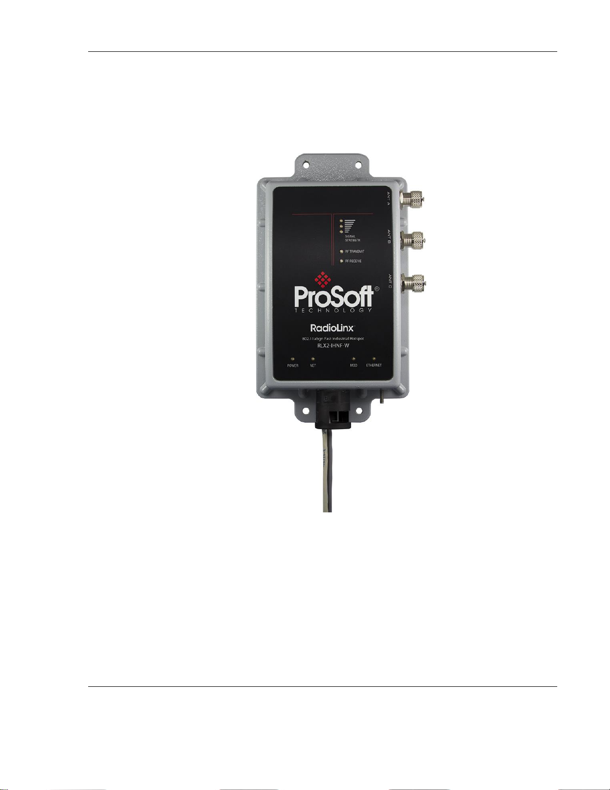
RLX2-IHNF-W-A (FCC)
RLX2-IHNF-W-E (ETSI)
These two radios represent the weatherproof versions for the RLX2-IHNF. Three
antennas perform the same functions as those on the RLX2-IHNF.
Page 16 of 212 ProSoft Technology, Inc.
June 15, 2015
Page 17
RLX2 Industrial Hotspot Series
RLX2-IHNF-WC
This version represents a weatherproof, hazardous location radio. It is a conduit
version and is Class I, DIV 2 compliant. Three antennas perform the same
functions as those in the RLX2-IHNF-W-A and RLX2-IHNF-W-E.
ProSoft Technology, Inc. Page 17 of 212
June 15, 2015
Page 18
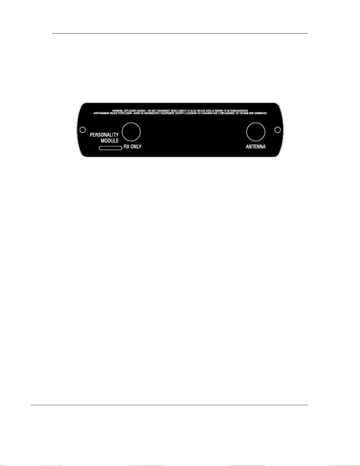
RLX2 Industrial Hotspot Series
RLX2-IHW
This radio uses the right-side antenna port for transmit and receive. An optional
receive-only antenna can be attached to the left-side antenna port to improve
performance in some applications.
Page 18 of 212 ProSoft Technology, Inc.
June 15, 2015
Page 19

RLX2 Industrial Hotspot Series
Qty.
Part Name
Part Number
Part Description
1
RLX2 Series Radio
RLX2-IHNF-W
RadioLinx® RLX2 802.11 Industrial Hotspot
Weatherproof
1
ProSoft Solutions DVD
DVD-001
Contains sample programs, utilities, firmware
images, and documentation for RadioLinx®
products.
1
U-mounting bracket
Pole mounting bracket
1
M12 Cap
Water tight cap
Part Name
Part Number
Part Description
Locking Clip
CUL-M12-LOCKCLIP
7 foot (2m),
M12 to RJ45,
Network
Cable/ PoE
or
33 foot (10m),
M12 to RJ45,
Network
Cable/PoE
CULRJ45-M12-007
CULRJ45-M12-033
7 foot Network PoE cable
33 foot Network PoE cable
33 foot (10m),
M12 to
unterminated
leads, Power
Cable
or
10 foot (3m),
M12 to
unterminated
leads, Power
Cable
CULPWR-M12-033
CUPLWR-M12-010
33 foot Power Cable
10 foot Power Cable
Package Contents
Standard Content RLX2-IHNF-W
The following components are included with Weatherproof RLX2 radio products:
RLX2-IHNF-W Cables
The following cables are for outdoor locations (sold separately).
ProSoft Technology, Inc. Page 19 of 212
June 15, 2015
Page 20

RLX2 Industrial Hotspot Series
Qty.
Part Name
Part Number
Part Description
1
RLX2 Series Radio
Varies
RadioLinx® RLX2 802.11 Industrial Hotspot
1
5 foot CAT 6 Ethernet
PoE cable
Preinstalled 6 foot CAT 6 Ethernet PoE cable
1
5 foot flying leads power
cable
Preinstalled 6 foot flying leads power cable
2
U bolts for mounting
1
Oval Clip & Seal Cap
Oval clip and seal cap for conduit connections
1
ProSoft Solutions DVD
DVD-001
Contains sample programs, utilities, firmware
images, and documentation for RadioLinx®
products.
Qty.
Part Name
Part Number
Part Description
1
RLX2 Series Radio
Varies
RadioLinx® RLX2 802.11 Industrial Hotspot
1
Personality Module
001-005700
Industrial Grade MicroSD card (blank, in plastic
bag)
1
Power Connector
002-0116
Mating power connector for the RLX2 radios,
for attachment to customer’s power supply.
1
Power Connector Wiring
Tool
357-0061
Tool to assist wiring the power connector.
1
Antenna
A2502S-OA
2 dBi Omni RP-SMA articulating, 2.4/5GHz. This
antenna is suitable for all RLX2 radio products.
1
ProSoft Solutions DVD
DVD-001
Contains sample programs, utilities, firmware
images, and documentation for RadioLinx®
products.
Standard Contents (RLX2-IHNF-WC)
The following components are included with Weatherproof Hazardous Location RLX2
radio products:
Standard Contents (All other radios)
The following components are included with standard RLX2 radio products:
Page 20 of 212 ProSoft Technology, Inc.
June 15, 2015
Page 21

RLX2 Industrial Hotspot Series
Qty.
Part Name
Part Number
Part Description
1
Power Supply
RL-PS007-2
AC Power Adapter, 12V1.6A w/2 pin & 4 plug
Set
1
Cable
RL-CBL025
5 foot Ethernet Straight-Thru Cable
1
Cable
085-1007
6 foot RS232 serial cable
1
Adapter
HRDNULL-DB9
RS232 null modem serial adapter
Industrial Hotspot Bench Test Kit (RLX-IHBTK)
The standard radio products are intended for deployment into production systems and
do not include accessory power supplies or cables. For bench testing of radios, an
optional bench test kit provides these accessories:
Personality Module
The RLX2 series of industrial hotspots include a feature for quickly moving the
configuration from an installed radio to a replacement using a provided MicroSD card.
This feature reduces the time to replacement of a damaged radio. Consideration of how
to use this feature in advance of installation is necessary to take advantage of this
feature.
Note: The RLX2-IHNF-W and WC do not have a Personality Module.
Important: Before installing, please verify all listed product items are present. If any of these
components are missing, please contact ProSoft Technology Support for replacements.
ProSoft Technology, Inc. Page 21 of 212
June 15, 2015
Page 22

RLX2 Industrial Hotspot Series
The RadioLinx Industrial Hotspot Browser
Configuration Tool
The Industrial Hotspot Browser configuration tool (hereafter called the IH Browser) is
used for setup and configuration of the RLX2 radios. It is designed for personal
computers running Microsoft Windows operating systems. The IH Browser can be
installed from the product DVD shipped with the RLX2 radio product, or it can be
downloaded from the ProSoft website.
System Requirements
The RLX2-IHx browser is designed for Microsoft Windows XP, 2000, and 2003. Minimum
hardware requirements are:
Pentium
Supported operating systems:
o Microsoft Windows XP Professional 32-bit with Service Pack 3
o Microsoft Windows 7 Professional 32- or 64-bit, with Service Pack 1
o Microsoft Windows 8 Release Preview 32- or 64-bit.
®
II 450 MHz minimum. Pentium III 733 MHz (or better) recommended
Other Microsoft Windows operating system versions may work but have not
been tested by ProSoft and are not officially supported.
128 Mbytes of RAM minimum, 256 Mbytes or more of RAM recommended
100 MB available hard drive space
256-color VGA graphics adapter, 800 x 600 minimum resolution (True Color 1024 x
768 resolution or better recommended)
At least one 100BASET or 1000BASET network interface. A second interface is often
useful to setup a small private network for initial configuration and testing.
In addition, these items may be needed:
A DVD-ROM drive, if installing the RadioLinx IH Browser from optical media.
An RS-232 port on the PC or a USB-to-serial convertor cable, to use serial
encapsulation features or to access system debugging information.
An internet connection may be useful to download updated product information
from the ProSoft Technology website at http://www.ProSoft-Technology.com.
Installation from DVD
1. Insert the ProSoft Solutions DVD in the DVD drive. On most computers, a menu
screen will open automatically. If a menu does not appear within a few seconds,
follow these steps:
Page 22 of 212 ProSoft Technology, Inc.
June 15, 2015
Page 23
RLX2 Industrial Hotspot Series
2. Click the Start button, and then choose Run.
3. In the Run dialog box, click the Browse button.
4. In the Browse dialog box, click "My Computer". In the list of drives, choose the
DVD drive where the ProSoft Solutions DVD was inserted.
5. Open the DVD and double-click the ProSoft_DVD.exe file to run it.
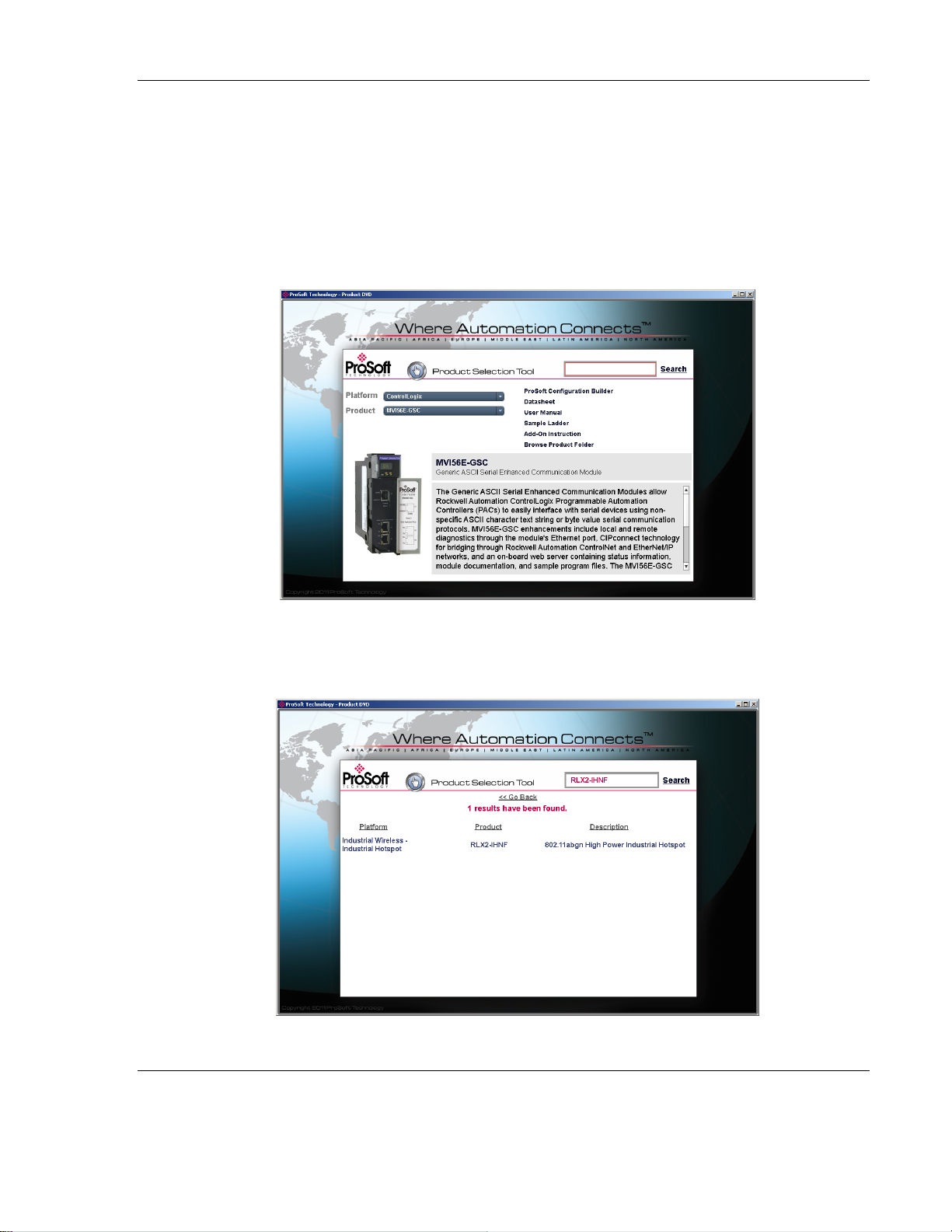
6. The DVD should display a startup screen like this:
7. Type the product name into the search box and click Search. Here is an example
of searching for the RLX2-IHNF:
ProSoft Technology, Inc. Page 23 of 212
June 15, 2015
Page 24
RLX2 Industrial Hotspot Series
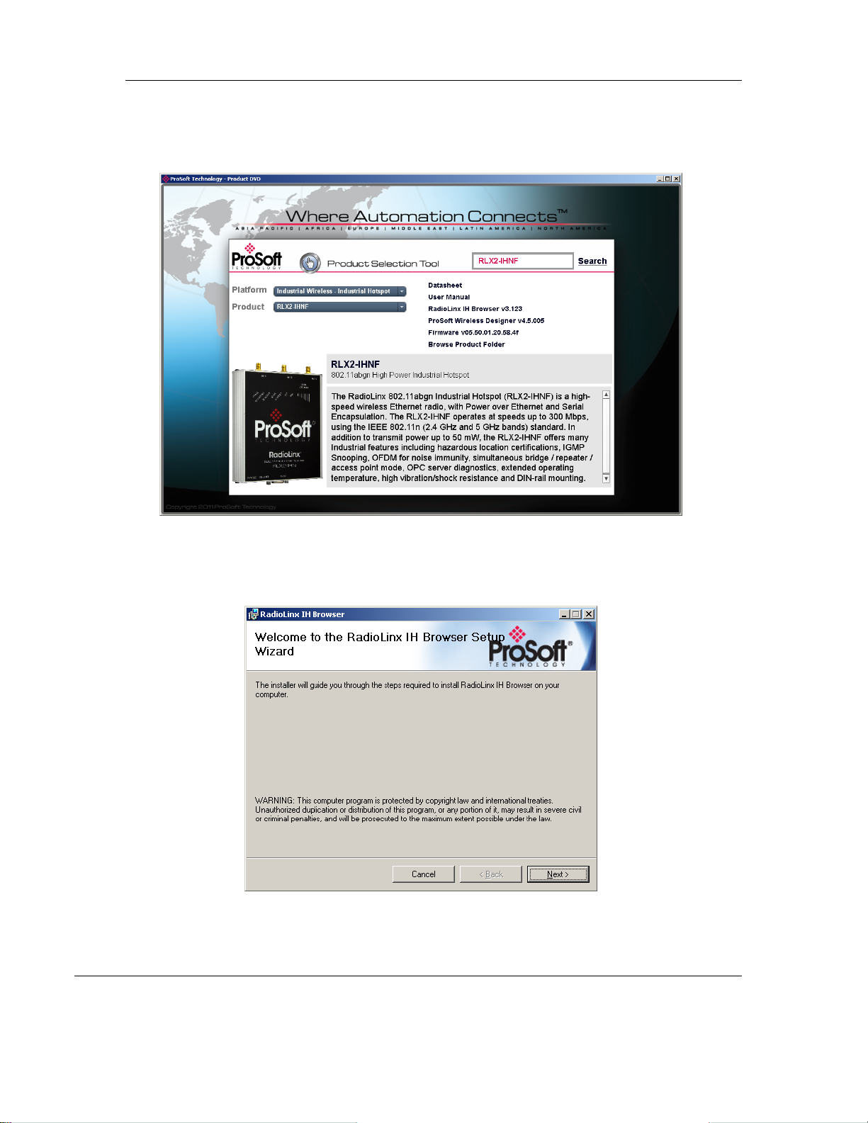
8. Click on the Product Name. The screen displays the contents for this module.
9. Double-click on RadioLinx IH Browser v3.4 (or a newer version if available) and
the installation wizard should launch:
Page 24 of 212 ProSoft Technology, Inc.
June 15, 2015
Page 25

RLX2 Industrial Hotspot Series
10. Follow the instructions on the installation wizard to install the program with its
default location and settings.
11. When the installation finishes, a prompt to restart the computer may appear if
certain files were in use during installation. The updated files will be installed
during the restart process.
Installation from Download File
If the RadioLinx IH Browser was downloaded from the ProSoft website, it will be
packaged as a compressed zip file. Double–click the zip file after downloading. The
Windows extraction wizard will extract the installation file (RadioLinx IH Browser
3.130.msi or a newer version.) Then double-click the .msi file to install the IH Browser.
ProSoft Technology, Inc. Page 25 of 212
June 15, 2015
Page 26

Page 27

RLX2 Industrial Hotspot Series
R L X 2 Q U I C K S E T U P
This section describes how to setup RLX2 radios in a minimal configuration before
deploying them in the permanent installation. It will help verify the radios are
operational along with getting familiar with basic configuration procedures.
Note that the procedures described in this section assume the radios are in their default
configurations as shipped by ProSoft. If that is not the case, reset the radios to factory
defaults before attempting these procedures.
In any given network, there must be one radio acting as a Master, and the other radios
will be configured as Repeaters or Clients. Generally there is only one Master radio per
network.
Because most wireless networks consist of one Master radio and multiple Repeaters, all
RLX2 radios are shipped from ProSoft pre-configured as Repeaters. Hence our first task
is to configure one radio as the network Master.
IMPORTANT: If a ProSoft Power adapter RL-PS007-2 (supplied with the RLX-IHBTK Bench Test
Kit) is not present, see instructions on wiring the power connector in this manual.
ProSoft Technology, Inc. Page 27 of 212
June 15, 2015
Page 28
RLX2 Industrial Hotspot Series
Setup Master Radio
The first step is to select the radio to use as a Master. All RLX2 radios in a network are
typically the same model, although this is not necessary.
IMPORTANT: The only RLX2 radios that do not have any channels in common with each other are
the RLX2-IHA and RLX2-IHG. The RLX2-IHW and RLX2-IHNF radios can communicate with each
other and with the RLX2-IHA and RLX2-IHG radios.
If all the radios are present on the workbench, antennas may not be needed for this
configuration exercise. Radios without antennas may have sufficient signal strength to
link over short distances, without radiating or receiving unnecessary RF energy in the
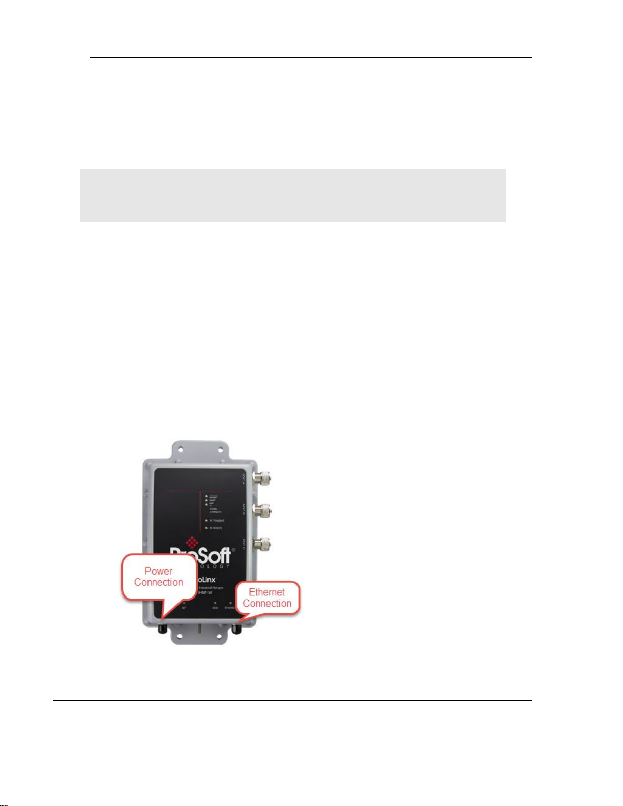
surrounding environment. However, connecting an antenna to the master radio is
recommended. The connections needed are on the bottom of the radio.
Note: The RLX2-IHNF-W Weatherproof radio uses M12 connectors for Ethernet and
Power. You can order these cables directly from ProSoft.
For RLX2-IHNF-W Radios
1. Attach an Ethernet cable with an M12 connector to the specified port shown on the
designated Master RLX2 radio. Make sure that this network connection is on the
same subnet as the PC running the IH Browser configuration software.
Page 28 of 212 ProSoft Technology, Inc.
June 15, 2015
Page 29
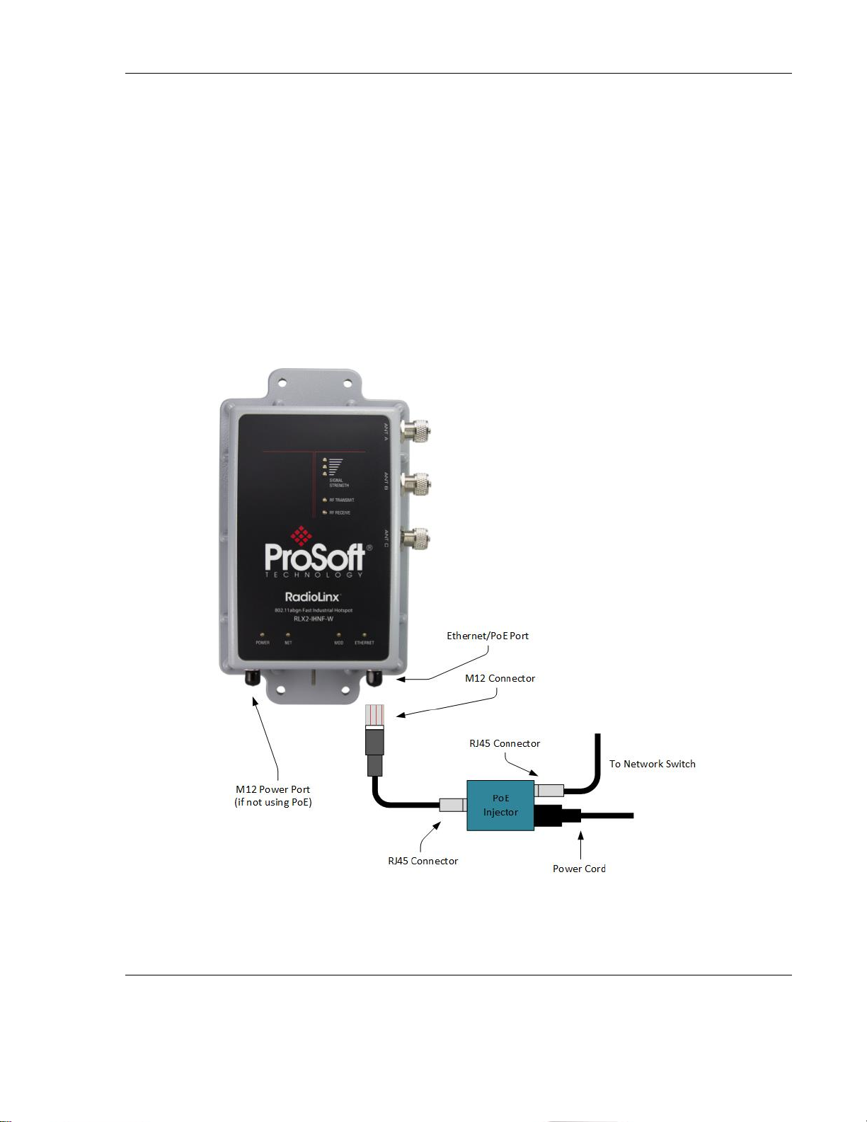
RLX2 Industrial Hotspot Series
2. Connect the power cable with an M12 connector to the specified port shown.
Note: The RLX2-IHNF-W radio can be powered over Ethernet (POE) with an
approved injector available from ProSoft. In this case, the Power connector would
not be used.
If PoE is used, please cap the Power Connector with the supplied M12 Waterproof
Cap before installation.
3. Connect the Ethernet cable through the PoE injector (if using PoE) and then into the
network switch.
Note: Most off-the-shelf PoE Injectors work with this unit except for the 802.3at/
PoE+ Injectors.
Note: The M12 PoE cable is not included with the radio but can be ordered through
ProSoft.
ProSoft Technology, Inc. Page 29 of 212
June 15, 2015
Page 30

RLX2 Industrial Hotspot Series
WARNING: Do not connect or disconnect the PoE connection when energized.
Antennas are to be installed in accordance with Control Drawing 06/2514.
For RLX2-IHNF-WC Radios
This radio is suitable for Class I, DIV2 hazardous locations.
This radio contains a set of wires that protrude through a single conduit hub. One wire
is terminated with an RJ45 connector for Ethernet connections. This wire can also
supply power if attached to a PoE Injector.
The second wire supplies power to the radio if a PoE Injector is not used. If not using
these cables, simply terminate them.
To install this radio….
1. Place a Seal Cap over the top of the conduit.
2. Run both wires down through the conduit.
3. Push the conduit up into the permanently installed connector on the bottom of the
radio. Push it up as far as it will go.
Page 30 of 212 ProSoft Technology, Inc.
June 15, 2015
Page 31

RLX2 Industrial Hotspot Series
Note: Recommend conduit is Thomas & Betts® PMA Series, Cat. No. CYLT-23B.
ProSoft Technology, Inc. Page 31 of 212
June 15, 2015
Page 32

RLX2 Industrial Hotspot Series
4. Place the Oval Clip into the opening in the Connector until it snaps into place. This
secures the conduit to the connector.
Note: In the event that you have to remove the conduit, simply remove the Oval Clip
using a screwdriver to pry it out. The conduit can now be removed from the Connector.
Page 32 of 212 ProSoft Technology, Inc.
June 15, 2015
Page 33

RLX2 Industrial Hotspot Series
The wire with the RJ45 connector is your Ethernet connection and supports Power over
Ethernet (PoE). If you are not using PoE, the other wire set is used to power the
module.
Note: If you are using PoE to provide power to the module, the additional power cables
should be terminated inside the junction box during installation to prevent the wire
assembly from shorting out.
WARNING: Do not connect or disconnect the PoE connection when energized.
ProSoft Technology, Inc. Page 33 of 212
June 15, 2015
Page 34

RLX2 Industrial Hotspot Series
Page 34 of 212 ProSoft Technology, Inc.
June 15, 2015
Page 35

RLX2 Industrial Hotspot Series
Antennas are to be installed in accordance with Control Drawing 06/2514. See the
Antenna section in this manual.
For All Other Radios
1. Attach an Ethernet cable to the designated master RLX2 radio. Make sure this
network connection is on the same subnet as the PC running the IH Browser
configuration software.
Note: The Ethernet DATA LED should come on when data is sent or received from the radio. The
Ethernet SPEED LED indicates the speed of the Ethernet connection. The SPEED LED is off for
10 Base T, on for 100 Base T, and blinks about once every two seconds for 1000 Base T links.
Power-Up the Radios
1. Power up the radio. There is no On/Off Switch. Power is applied when the power
cord connection is made to the RLX2 radio.
The power LED should illuminate with an amber color, then go out for a few seconds
during initialization, then finally come back on green. This process will take 10 to 15
seconds. Once the power LED is green, the radio has booted and is operational.
Other LEDs may become active as well.
2. Take note of the MAC address of the RLX2 radio. This is printed on a label attached
to the front of the radio. The MAC address should be something like 00-0D-8D-XX-
YY-ZZ (e.g. 00-0D-8D-F0-5C-8E.) This number uniquely identifies the radio on the
network.
3. Run the IH Browser configuration software.
ProSoft Technology, Inc. Page 35 of 212
June 15, 2015
Page 36

RLX2 Industrial Hotspot Series
If the display is different than above, use the IH Browser toolbar controls to clear and
refresh the display:
The “erase” tool clears the display
The “search” tool rescans the network for RLX2 radios
If no radios appear in the list, see Section 0 on troubleshooting missing radios.
4. In particular, note the line listing the MAC address of the RLX2 radio. If the radio is
on a network with a DHCP server, it will obtain an IP address via DHCP. If not, the
radio will appear with an IP address of 0.0.0.0 as shown above.
5. Assign the RLX2 a valid IP address for the network. Do this by right-clicking on the
radio’s row in the IH Browser display and selecting Assign IP from the context menu.
Page 36 of 212 ProSoft Technology, Inc.
June 15, 2015
Page 37

6. The Assign Temporary IP Address dialog opens:
RLX2 Industrial Hotspot Series
The Unused IP’s: box contains a number of IP addresses that are currently available on
the network. Select one of them and click OK. (In this example,192.168.1.250 is used)
IMPORTANT: Be sure to click OK or the selected IP address will not be assigned to the radio.
7. The Access Point utility warns you of the temporary selection.
8. Click OK.
9. Open a web browser on the PC, and enter the IP address that was just assigned to
the radio (e.g. http://192.168.1.250). A login screen opens:
ProSoft Technology, Inc. Page 37 of 212
June 15, 2015
Page 38

RLX2 Industrial Hotspot Series
The default password is “password”. Enter that in the text box and click Login.
10. The radio’s main webpage opens: (Some fields may be different depending on the
specific radio model).
11. Select the Master radio button and select Channel 1 (2412 MHz) as shown in the
following example.
Page 38 of 212 ProSoft Technology, Inc.
June 15, 2015
Page 39

RLX2 Industrial Hotspot Series
Note: Select Channel 36 (5180 MHz) if the Master radio is an RLX2-IHA.
12. If the IP address is manually set as previously described, permanently set the IP
address by selecting the Use the following IP address radio button:
ProSoft Technology, Inc. Page 39 of 212
June 15, 2015
Page 40

RLX2 Industrial Hotspot Series
13. Click the Apply Changes button and the Radio reboots.
A progress bar is visible during reboot.
Upon successful reboot, the RLX2 radio is shown as a Master in the IH Browser window:
Page 40 of 212 ProSoft Technology, Inc.
June 15, 2015
Page 41

RLX2 Industrial Hotspot Series
ProSoft Technology, Inc. Page 41 of 212
June 15, 2015
Page 42

RLX2 Industrial Hotspot Series
Setup Repeater Radio
Since we haven’t changed any factory-default configuration parameters in the Master
radio (other than to make it a Master), additional RLX2 radios in their default shipping
configuration should link to it as soon as power is applied to them.
1. Attach power to another RLX2 radio. The Ethernet cable does not need to be
attached to it at this time.
2. After the radio is booted, the radio should appear in the IH Browser:
Note that the Repeater radio above (whose MAC address ends in BF in the above
example) has linked to the Master (whose MAC address ends in BE) and there is a
signal strength indication of –85 dBm.
3. Attach an Ethernet cable, and assign a unique IP address to the Repeater. In this
example, the Repeater is assigned an IP address of 192.168.1.251:
After setting the Repeater’s IP address, remove its Ethernet connection.
4. On the PC, open a command prompt window and attempt to ping the Repeater’s IP
address. The Master should ping the Repeater over the air:
Page 42 of 212 ProSoft Technology, Inc.
June 15, 2015
Page 43

RLX2 Industrial Hotspot Series
5. Congratulations! The RLX2 wireless network is now configured. Additional Repeaters
can be configured by repeating the steps listed above.
ProSoft Technology, Inc. Page 43 of 212
June 15, 2015
Page 44

RLX2 Industrial Hotspot Series
Repeater
Client
Number of attached
Ethernet devices
supported
Many (up to limits of
network)
One
Can connect to other
RLX2 Repeaters?
Yes
No
Can connect to nonProSoft Access Points
(Masters)?
No
Yes
MAC address seen on
network
Repeater radio’s MAC
address
MAC address of
connected device, or
user-specified MAC
address.
Setup Client Radio
RLX2 radios can be configured in Client mode. Client mode radios only support one
wired network device, but can connect to third-party 802.11 Access Points. The
following table highlights the most significant differences between Repeater and Client
modes on RLX2 radios:
Client mode radios are not often necessary in Industrial network applications. If the
need for a Client RLX2 radio in the system is not needed, this example configuration can
be skipped.
The most straightforward way to test a Client mode radio configuration is with a second
PC connected as the downstream network device from a Client radio. We will assume
such a setup in the following example, and will connect to the Master radio we
configured previously.
1. Connect the client radio to the same network as the configuration PC running the IH
browser. Assign it an IP address as described above. Open the configuration
webpage and change the radio to Client mode as shown:
Page 44 of 212 ProSoft Technology, Inc.
June 15, 2015
Page 45

RLX2 Industrial Hotspot Series
Click Apply Changes. When the radio reboots, the IH Browser will display:
2. Power off the Client radio and disconnect the Ethernet cable from the configuration
PC.
3. Connect the Ethernet cable to an Ethernet port on another PC, and power up the
Client radio. (The radio must be powered up after attaching the Ethernet cable to
the new PC so the radio will register the MAC address of the PCs network interface.)
Ensure the IP address of the Ethernet interface on the PC is on the same subnet as
the network of the Client Radio. For this example, set the IP address of the PC
interface to 192.168.1.100. Here is an example of doing so in Windows 7:
ProSoft Technology, Inc. Page 45 of 212
June 15, 2015
Page 46

RLX2 Industrial Hotspot Series
4. Open a command prompt on the client PC, and try to ping the IP address of the Master
radio. It should respond as seen below:
Install Replacement Radio Using Personality Module
If the radio being installed is replacing an existing radio, and a Personality Module was
already installed in the existing radio, then no manual configuration is necessary.
Remove the Personality Module from the existing radio with the stored configuration
Page 46 of 212 ProSoft Technology, Inc.
June 15, 2015
Page 47

RLX2 Industrial Hotspot Series
and install it in the new radio. On power up of the new RLX2 Industrial Hotspot, all
configuration settings from the radio being replaced are automatically used.
Note: The RLX2-IHNF-W or WC radios do not have a Personality Module and must be
configured using the steps described in this manual.
Planning the Network
Before configuring and installing the wireless network, it may help to create a plan. The
following points assume a bridge network of masters and repeaters. Clients can also be
configured to work with devices on existing wireless LANs. For information, see Setup
Client Radio (page 44).
The simplest way to design the physical network of radios, antennas, connectors, cables,
amplifiers and other accessories is to use ProSoft Wireless Designer (page 49). This is a
freely-available software application that determines the hardware needs based on the
user’s answers to a few questions.
The software will generate a Bill of Materials specifying all the components needed for
the installation. ProSoft Wireless Design is included on the optical media supplied with
the RLX2 radio, and is also available for downloading from the ProSoft website.
To begin, identify the potential radio locations. For example, the master radio may
be installed near a PC in a central plant location (This PC can configure the radios
through the Radio Configuration / Diagnostic Utility). If the plant is an oil refinery,
for example, radios may need to be installed near the oil tanks.
The next important issue is how to link the radios. Unless the radios are very close
together, make sure that each pair of radio antennas in the network has a line of
sight between them. In other words, visibility is needed from one antenna to
another, either with the naked eye or with binoculars.
If a line of sight does not exist between antennas, an additional site is needed for
installing a repeater radio. This site will create a bridge between the radio
antennas.
Choose the appropriate antennas for the network. If an antenna will be connected
to the radio by a long cable, a power amplifier (available from ProSoft Technology)
may be needed. The more distance between an antenna and its radio, the more
signal loss the radio will have.
ProSoft Wireless Designer can suggest suitable antennas for the application based
on frequency band, data rate, distance, power output level, and other factors.
ProSoft Technology, Inc. Page 47 of 212
June 15, 2015
Page 48

RLX2 Industrial Hotspot Series
Consider drawing up the network plans on paper. As part of the drawing, assign a
logical name to each radio. These names can be assigned in the Radio Configuration
/ Diagnostic Utility.
As part of the planning, a site survey may be helpful. You can hire ProSoft
Technology or a surveyor to perform a survey, or you can conduct the survey on
your own.
Protect radios from direct exposure to weather, and provide an adequate, stable
power source. Make sure the plan complies with the radio’s power requirements
and cable specifications.
Important: Radios and antennas must be located at least 8 inches (20 cm) away from personnel.
Page 48 of 212 ProSoft Technology, Inc.
June 15, 2015
Page 49

How many radios are in the network?
Master ID:
Repeater ID:
Client ID:
Locations:
Is there a Line of Sight between them?
What type of antennas will be used in the
network?
Will the Personality Module configuration
restoration feature be used?
Installation Questions
The following questions will help in getting familiar with the system.
RLX2 Industrial Hotspot Series
Planning the Physical Installation
A network's performance is affected by attributes specific to the installation site.
Consider the following cautions, where possible, to optimize the network installation:
Design the network to use less than 2048 radios (per network)
Place radios within the specified 15 miles of each other
Add repeater to extend distance or where line of sight is limited
Radios or antennas CANNOT be placed within 8 inches (20 cm) of personnel
Though radio frequency communication is reliable, sometimes its performance can be
affected by intangibles. A good network installation plan includes time and resources
for performance testing and installation changes.
Test the installation plan (page 57) before the network installation is complete.
ProSoft Wireless Designer
ProSoft Wireless Designer is a freely-available software tool to simplify the task of
specifying a ProSoft wireless installation. The following screenshot shows an example of
configuring wireless links and estimates of signal quality:
ProSoft Technology, Inc. Page 49 of 212
June 15, 2015
Page 50

RLX2 Industrial Hotspot Series
Page 50 of 212 ProSoft Technology, Inc.
June 15, 2015
Page 51

RLX2 Industrial Hotspot Series
ProSoft Wireless Designer can also compute a Bill Of Materials (BOM) for a complete
radio installation, including antennas, cables, connectors and other required materials:
It is included on the DVD with the RLX2 radio, or it can be downloaded from the ProSoft
website. ProSoft Wireless Designer provides a variety of views containing an accurate
description of each site in a wireless network, including:
Visual diagram of site layout
Location (latitude/longitude, based on GPS coordinates)
Radio type, frequency range, and country-specific channel and power requirements
Length, type and estimated signal loss for cables
Required accessories, including lightning protection, cable adaptors and antennas
Complete parts list
ProSoft technical personnel use ProSoft Wireless Designer when conducting site audits
for customers, and then provide customers with a complete list of components and a
detailed description for each site and link. Customers can use this information to
understand and visualize their network, and provide necessary information for technical
support and maintenance.
ProSoft Technology, Inc. Page 51 of 212
June 15, 2015
Page 52

RLX2 Industrial Hotspot Series
Functional Specifications:
Contains a database of all currently available RadioLinx radios, antennas, cables,
connectors and accessories
Exports Parts List, Site and Link Details, and Wizard settings into a variety of
common file formats, for import into applications such as spreadsheets, databases
and word processors
Checks wireless link feasibility based on path length and recommended accessories
Predicts signal strength based on distance, local regulations and hardware choices
Fully documents the ProSoft Wireless network plan
ProSoft Wireless Designer Installation
1 When installing from the product DVD, search for the product, then double-click on
the ProSoft Wireless Designer item on the product menu (see the red arrow
below). This action starts the installation wizard.
2 When using the downloaded application from the ProSoft website, it is packaged as
a zip archive. Double-click the zip archive to extract the installation file INSTALLER.MSI,
double-click it to start the installation.
Page 52 of 212 ProSoft Technology, Inc.
June 15, 2015
Page 53

3 The installer wizard should start and look like this:
RLX2 Industrial Hotspot Series
4 Follow the instructions on the installation wizard to install the program.
5 Click FINISH to complete the installation. If prompted to restart the computer, save
all work, close the applications, and allow the computer to restart.
6 Refer to the user manual for ProSoft Wireless Designer and its online help for
detailed information.
Personality Module Configuration Restoration
The RLX2 Series of Industrial Hotspots include a feature for quickly adopting the
configuration from an installed radio to a replacement using a provided MicroSD
card. This feature reduces the time to replace a damaged radio by eliminating
the need to manually configure the replacement radio. Consideration of how to
use this feature in advance of installation is necessary to take advantage of this
feature.
ProSoft Technology, Inc. Page 53 of 212
June 15, 2015
Page 54

RLX2 Industrial Hotspot Series
By default, the RLX2 series of radios will write configuration changes to a
MicroSD card (Personality Module) whenever configuration changes are made
and a card is present. The RLX2 (by default) will also read the MicroSD card’s
configuration when powered on and use the stored configuration.
While this feature can save much time when a field replacement is necessary, it
is also a potential security risk. The configuration stored on the MicroSD could
be inserted into another radio, and the radio could then access the network.
The file itself on the MicroSD card is encrypted so the configuration information
(principally the configuration password and encryption key) cannot be
extracted. Physical security of the radios and the MicroSD card is highly
recommended.
If the Personality Module feature will not be used, it is recommended that you
turn Auto-Clone and Auto-Write off.
Page 54 of 212 ProSoft Technology, Inc.
June 15, 2015
Page 55

RLX2 Industrial Hotspot Series
I N S T A L L I N G T H E R A D I O S
If possible, configure all the radios side by side in an office setting and make sure they
link before installing them in the field. If feasible, test with the radios and end-device
equipment together before they are installed in the field.
If the Personality Module feature is to be used, remove the MicroSD card from the
plastic bag and insert it into the Personality Module slot in each radio prior to
configuration. After the configuration is saved on the main web page (or written to the
card in Advanced Settings), the MicroSD may stay in the radio or be stored in some
other location. The supplied plastic bag includes a sheet to record the MAC ID and
Radio Name. It is important to keep the MicroSD in a known and secure location in case
it is needed for use on a replacement radio.
Important: If the radios are close enough to each other that their received signal strength is
greater than -40dBm, performance may be degraded. Disconnect antennas from radios during
bench testing, or move the radios further apart from each other.
Tip: To make it easier to physically identify the radios, apply a label to each radio indicating the
radio name and IP address.
After each radio is configured using the IH Browser and the web configuration form, you
can install the radios and test their performance. Install the radios in their proposed
permanent locations, then temporarily place each radio’s antenna near its proposed
mounting location. The temporary placement of the antenna can be by hand.
However, with this testing method, one person must hold the antenna while another
monitors the radio’s signal strength.
ProSoft Technology, Inc. Page 55 of 212
June 15, 2015
Page 56

RLX2 Industrial Hotspot Series
To see how a radio is linked in the network, make sure that the radio is connected to a
PC, and select Topology View from the View menu in the IH Browser.
The Topology view shows a diagram of the network’s wireless connections. Use this
view to see whether all the radios are linked, and approve of the way the radios are
linked.
A radio that is not linked to a parent will show as a circle outlined by a flashing dashed
red line. It may be near the bottom of the window. Scroll down to view all available
radios. To change how radios link to the network, see Parent Link settings (page 82).
Refer to Improve Signal Quality (page 66) for more information on overcoming poor
connectivity.
Page 56 of 212 ProSoft Technology, Inc.
June 15, 2015
Page 57

RLX2 Industrial Hotspot Series
Connecting Antennas
Each radio must have an antenna connected to the Main antenna port on the RLX2
radio; without an antenna for each radio, the network will not function if the radios are
more than a few meters apart. You should always connect the number of antennas on
Port A, PortA-PortC, or PortA-PortB-PortC, as indicated in the #antennas control. The
network will not function without all antennas installed.
All antennas for radios that communicate directly with each other should be mounted
so they have the same antenna polarity. Antennas with N-jack connectors cab be
mounted directly to the radio using an N-plug to N-plug adapter. Screw the antenna
onto the antenna port connector until it is snug.
For remote placement of antennas, an extension cable with N-plugs can be used.
Because the antenna cable attenuates the RF signal, use an antenna cable length that is
no longer than necessary to ensure optimum performance
Important: If the radio is to be used in a hazardous location, the radio must be mounted in an
enclosure approved for hazardous locations. The radio requires a separate cable connection to the
SMA connector that leads to an internal antenna.
Test the Network Installation Plan
Test proposed installations before finalizing the installation.
After the network and radios are configured:
Install the Master radio in its proposed permanent location
Cable the Configuration PC to the Master radio
Place the Remote radios in their proposed locations
Temporarily place each radio's antenna near its proposed mounting location. The
temporary placement of the antenna can be by hand. However, one person must
hold the antenna while the other person monitors the Remote radio's signal
strength displayed on the Configuration PC.
To improve the signal quality of each Remote radio:
Increase the height of the antenna's placement
Use higher-gain antennas
ProSoft Technology, Inc. Page 57 of 212
June 15, 2015
Page 58

RLX2 Industrial Hotspot Series
Increase the radio's transmission power, cable the radio to the Configuration PC,
and reconfigure it
Select a new location for the Remote radio and/or its antenna
Decrease the length of antenna cable
Determine and resolve sources of "electrical" noise which may be interfering with
the radio transmission
Add a repeater between the radios that are not communicating, or reconfigure an
existing radio as a repeater if line of sight is available
Page 58 of 212 ProSoft Technology, Inc.
June 15, 2015
Page 59

RLX2 Industrial Hotspot Series
D I A G N O S T I C S A N D T R O U B L E S H O O T I N G
Use the program’s diagnostic and signal strength settings at the top of the Radio
Settings window to make sure the network is working properly:
Signal Strength graph: This setting graphically shows the radio’s signal strength. The
graph will show the word Master if a master radio is selected. The graph will show
the word Scanning if the radio is scanning to find another radio to which to connect.
If the radio is not connected to a network and not currently scanning, the graph will
show the words Not Connected.
Update every: To update the diagnostic readings on a particular interval, specify the
interval (in seconds) in this field. The default is 15 second updates.
Read-only fields that appear with the diagnostic settings.
You can perform the following troubleshooting routines:
Check the Ethernet cable (page 61)
Retrieve the default password (page 63)
For more troubleshooting information, go to the ProSoft Technology web site at
www.prosoft-technology.com
ProSoft Technology, Inc. Page 59 of 212
June 15, 2015
Page 60

RLX2 Industrial Hotspot Series
Diagnostics
The Radio Configuration / Diagnostic Utility (Web configuration form for the radio)
provides information that can help troubleshoot problems with the radio.
Use the program’s diagnostic and signal strength settings at the top of the Radio
Settings window to make sure the network is working properly.
Signal Strength graph: This setting graphically shows the radio’s signal strength.
The graph will show the word Master if a master radio is selected.
The graph will show the word Scanning if the radio is scanning to find another radio
to which to connect.
If the radio is not connected to a network and not currently scanning, the graph will
show the words Not Connected.
If the radio is configured as a Repeater and has linked to a Master, the Signal
Strength graph will show a color-coded signal quality indication.
Update every: To update the diagnostic readings according to a particular time interval,
specify the interval (in seconds) in this field. After entering the new value, press Enter to
save the new value. Press Tab or click elsewhere to use the new value temporarily.
The following configuration forms in the Radio Configuration / Diagnostic Utility provide
information about current radio operation:
Address table (page 75)
Port status (page 76)
Available Parents
Read-only fields (page 72)
The following topics describe troubleshooting routines:
Check the Ethernet cable (page 61)
Retrieve the default password (page 63)
Troubleshoot IH Browser error messages (page 65)
Troubleshoot missing radios in the IH Browser (page 65)
For more troubleshooting information, visit the ProSoft Technology website at
www.prosoft-technology.com.
Page 60 of 212 ProSoft Technology, Inc.
June 15, 2015
Page 61

RLX2 Industrial Hotspot Series
Check the Ethernet Cable
If the radio’s Ethernet port is connected and the Ethernet LED does not light on the
radio, there may be a problem with the Ethernet cable. Verify the cable is plugged into
the radio at one end, and to an Ethernet hub or a 10/100/1000 Base-T Ethernet switch
at the other end.
If using the PoE injector, verify that the M12 to RJ45 cable is connected between the
radio and the injector and also that the Ethernet patch cable is connected between the
injector and switch.
Note: The RLX2 radio auto-detects the Ethernet connection type, and does not require a crossover
cable for direct connection to a PC.
ProSoft Technology, Inc. Page 61 of 212
June 15, 2015
Page 62

RLX2 Industrial Hotspot Series
LED
Description
POWER
While booting up
When fully operational
This bi-color LED comes up amber when power is first applied. After power is applied,
this LED will go out completely for about four seconds while internal hardware is
initialized. After initialization, the power LED comes on green, indicating the radio is
fully operational.
RF TRANSMIT
While transmitting data over the wireless interface
RF RECEIVE
While receiving data over the wireless interface
SERIAL
When serial data is received
ETHERNET
When Ethernet data is being transferred over the wireless interface
Note that the state of the front-panel ETHERNET LED may not necessarily correspond to
the state of the DATA LED on the Ethernet connector. The DATA LED indicates any
traffic over the wired link, while the ETHERNET LED indicates network data that will be
sent (or has been received from) the wireless link.
For example if the radio is pinged over the wired link, the DATA LED will blink but the
ETHERNET LED will not (because the ping packet was not transmitted over the air)
NET
Blinks if SD card with new configuration inserted
Reserved for future additional use.
MOD
Blinks if SD card with new configuration inserted
Reserved for future additional use.
LED Display
The RLX2 radio front panel includes a set of LEDs that indicate the radio’s status:
Page 62 of 212 ProSoft Technology, Inc.
June 15, 2015
Page 63

RLX2 Industrial Hotspot Series
LED
Description
Signal Strength
Blinks if SD card inserted with new configuration
This is for all radio modes.
Radios in Master mode:
No radios linked
One or more radios linked (right LED blinking).
DFS Channel Availability Check in progress (all LEDs blinking Amber)
Radios in Repeater or Client mode:
No Signal
Radio linked, Poor Signal
Radio linked, Fair Signal
Radio linked, Good Signal
Once the power cable and Ethernet cable are connected to the radio, the Power/Status
LED should illuminate green. The SPEED LED should indicate a valid wired link. The RF
Transmit and RF Receive LEDs should start to blink occasionally.
For Repeater or Client mode radios, all three Signal Strength LEDs will blink just after the
radio links to the Master’s signal but before it has been fully authenticated. Normally
this lasts only a few seconds. If it lasts longer or never turns solid it usually means the
encryption keys are not correct.
Retrieve the Default Password
ProSoft Technology, Inc. Page 63 of 212
June 15, 2015
If the password is unknown, the user will be unable to change the radio settings. The
user can retrieve the default password to use the software again, but will lose all the
settings that were programmed before.
RLX2-IHNF-W and RLX2-IHNF-WC Reset
1. Remove power from the radio.
2. Press the Reset button. The Reset button is located on the front of the unit just
under the ProSoft logo.
Page 64

RLX2 Industrial Hotspot Series
3. While holding down the button, apply power to the radio and continue to hold the
button down for 30 seconds.
The radio will be reset to its default settings including the password. You can now log in
using the default password “password”.
Resetting All Other Radios
To retrieve the default password and return the radio to its default settings:
1 Turn off power to the radio.
2 Locate the reset button hole.
3 Insert the end of a paperclip or similar device into the hole to press the reset
button.
Page 64 of 212 ProSoft Technology, Inc.
June 15, 2015
Page 65

RLX2 Industrial Hotspot Series
4 While holding the reset button in with a paperclip, attach power to the radio, and
continue to hold down the reset button for 30 seconds.
5 The radio will be reset to its default settings, including the password. The user
should now be able to log in using the default password, which is password.
Troubleshoot IH Browser Error messages
One error message commonly occurs when using the IH Browser, "Unable to scan for
AP's".
This error occurs when the IH Browser attempts to scan for radios and no valid network
connection exists on the PC, wired or wireless.
To correct this error, Confirm the PC has at least one active network (LAN) connection.
It could be a wired Ethernet connection or a wireless 802.11 connection.
Confirm the network connection has a valid IP address. The network connection might
need to have a static IP address assigned to it. Check the IP address of the network
connection to determine that one has been assigned.
Troubleshoot Missing Radios
If radios are not visible in the IH Browser, try the following:
First, click the SCAN button again. Scans are sent as broadcast messages, which can
be dropped in RF connections, requiring the user to scan again.
Second, disable any software firewall running on the PC (This is most common in
Windows XP and newer). Open the NETWORK CONNECTIONS folder in the Windows
Control Panel, then open the LOCAL AREA CONNECTION PROPERTIES window and verify
that the check box under INTERNET CONNECTION FIREWALL is not checked.
ProSoft Technology, Inc. Page 65 of 212
June 15, 2015
Page 66

RLX2 Industrial Hotspot Series
If the preceding approaches do not help, the PC running the IH Browser and the
radios are probably not connected to the same local network. Verify the
connections.
In topological view, any unlinked radios may be at the bottom of the window. Scroll
down to see all radios. If the radios still cannot be seen in the IH Browser, call
technical support.
Improve Signal Quality
To improve a radio’s signal quality, try the following steps:
Adjust the direction of the high-gain antennas.
Increase the height of the antenna’s placement.
Use higher-gain antennas or external preamplifiers.
Select a new location for the radio and/or its antenna.
Decrease the length of the antenna cable.
Determine and resolve sources of interfering electrical noise.
Add a repeater between radios that are not communicating.
Page 66 of 212 ProSoft Technology, Inc.
June 15, 2015
Page 67

RLX2 Industrial Hotspot Series
D E T A I L E D R A D I O C O N F I G U R A T I O N /
D I A G N O S T I C S
The RadioLinx Industrial Hotspot radio has a built-in Radio Configuration / Diagnostic
Utility (radio web configuration form) that allows the configuration of the radio from
any computer that can connect to the radio, through a wired Ethernet connection, or
through a Wireless connection.
A web browser such as Microsoft Internet Explorer or Firefox on a network-enabled
desktop computer, laptop or Personal Data Assistant (PDA) can be used to monitor and
change the settings within the RadioLinx Industrial Hotspot radio.
To open the Radio Configuration / Diagnostic Utility
1 In the RadioLinx Industrial Hotspot Browser, select the radio to configure from the
list view or topography view, and then click the right mouse button to open a
shortcut menu.
2 On the shortcut menu, choose Connect. The Radio Configuration / Diagnostic Utility
will open in the web browser.
or,
Double-click the selected radio to launch the Radio Configuration / Diagnostic
Utility.
Also, the Radio Configuration / Diagnostic Utility can be opened directly from the web
browser.
Important: The desktop computer, laptop, or PDA must be connected to the same network as the
RadioLinx Industrial Hotspot radio.
1 Open a web browser.
2 In the address bar, type "http://", followed by the IP address for the radio, and
then click the "Go" button. For example,
http://192.168.6.10
ProSoft Technology, Inc. Page 67 of 212
June 15, 2015
Page 68

RLX2 Industrial Hotspot Series
Read-Only Fields
Some of the fields on the Radio Configuration / Diagnostic Utility form are read-only,
meaning that the content of the field is provided for information only, and cannot be
directly modified.
Also note that depending on how the radio is configured, some fields and buttons may
be unavailable because they do not affect the configuration you have selected. Review
the topics in this section for more information on when and how to use each
configuration option.
Configuration Help
Help is available for each item in the Radio Configuration / Diagnostic Utility.
Page 68 of 212 ProSoft Technology, Inc.
June 15, 2015
Page 69

RLX2 Industrial Hotspot Series
To view a brief help message about any field on the screen, move the cursor over
the field (which turns blue), or use the [Tab] key, and refer to the text that appears
at the bottom of the screen.
To view more help about the selected field, click the field name. This action opens a
help page in a new browser window.
ProSoft Technology, Inc. Page 69 of 212
June 15, 2015
Page 70

RLX2 Industrial Hotspot Series
Page 70 of 212 ProSoft Technology, Inc.
June 15, 2015
Page 71

RLX2 Industrial Hotspot Series
To view the complete online documentation for the RLX2 radio, click the
button. This action opens the online documentation in a new browser window. Use
the Contents, Index and Search tabs in the left frame to navigate the help system.
ProSoft Technology, Inc. Page 71 of 212
June 15, 2015
Page 72

RLX2 Industrial Hotspot Series
Field
Description
Radio Name
The user assigned name of the radio.
Radio MAC
MAC address of the selected radio. The MAC ID is also printed on the side of
the radio.
Radio Type
The Model Number of this radio –Examples: RLX2-IHA, RLX2-IHG, RLX2-IHNF,
or RLX2-IHW.
Firmware
Version of firmware currently installed. All radios on the network must have
the same firmware versions installed to guarantee proper operations. For
more information on firmware versions, refer to Update firmware (page 132).
Update every
Value in seconds controls how often the web configuration form
automatically refreshes. To change the value temporarily, enter the new value
and press the [Tab] key. To change the value permanently, enter the new
value and press the [Enter] key.
Up Time
The length of time the radio has operated since the last system power-up or
last system reset.
Link Time
The length of time that the radio has been continuously connected to parent
radio.
Signal Strength
Strength of the signal from the Parent radio.
Parent MAC
MAC address of the parent radio to which the selected radio is linked.
Radio Status
The general radio status fields appear at the top of the Radio Configuration window.
Note: Different versions of the RLX2 Radios support different functionality. There may be more or
fewer options on this page, depending on the version of the radio.
Use the settings in the Radio Status panel to view the current settings for this radio.
Page 72 of 212 ProSoft Technology, Inc.
June 15, 2015
Page 73

RLX2 Industrial Hotspot Series
Field
Description
Branch Length
Number of RF links from the radio to the master radio.
# Radios Linked
Number of other radios that are linked to this radio.
Current Channel
Channel upon which the radio is currently operating. For a Master, this would
match the channel set below. For a Repeater, this would be the channel its
Parent is on.
When the Link Mode indicates that the unit is in 40 MHz mode, this field
indicates the main channel number first followed by the extension channel’s
number.
Link Mode
The 802.11 Mode with which the radio is currently operating. For a Master,
this would be the highest mode supported. For a Repeater, this would be the
highest common mode supported by the settings of the Repeater and Parent,
and the capability of the radio channel.
Available Parents
Click this button to view the list of Access Points and Bridges (Parents) from
which this radio can detect beacons. This button is only available when the
radio type is Repeater.
Address Table
Click this button to view a list of MAC addresses for devices entered in the
radio’s address table.
Port Status
Click this button to view the spanning tree status of each bridge port (RF ports
and the RJ45 Ethernet port).
Available Parents
Note: The Available Parents form is not available when the radio type is Master.
This page is helpful for viewing:
Possible parents for a repeater. The current parent should normally be the radio
with the lowest cost and a matching SSID.
Other 802.11 networks in the area.
ProSoft Technology, Inc. Page 73 of 212
June 15, 2015
Page 74

RLX2 Industrial Hotspot Series
Field
Description
Only Show Same SSID
Select (check) this box to restrict the list of available parents to those with
the same SSID as the radio you are configuring.
Refresh
Click this button to re-scan the network and update the devices in the list.
Mac ID
A unique hexadecimal number that identifies any Ethernet device.
SSID
Network Name (Service Set Identifier).
Channel
The radio channel on which the device is transmitting. The channel list
indicates the channel number as well as the frequency (2.4 GHz or 5 GHz
bands).
Important: The RadioLinx RLX2 radio is supplied with a dual-band
antenna that supports both frequency ranges. If you use a different
antenna with the RLX2 radio, you must choose a channel and
frequency range supported by the antenna.
RSSI
Received Signal Strength Indication.
Security
The encryption type enabled for the device.
Speed
The IEEE 802.11 connection speed (a, b, g or n). The RadioLinx RLX2 radio
supports all of these 802.11 connection speeds.
Cost
Parent selection cost.
Age
The length of time (in seconds) since the radio last saw a packet from this
MAC address
Hops
The number of hops to the Master. A value of 0 (zero) is shown for nonProSoft devices.
This list contains both 802.11 devices that are part of the same SSID as the RLX2 itself
(for example, "Minerals") as well as devices that belong to different SSIDs (for example,
"Network1" and "ProSoftInternal"). This list is updated continuously and can be used for
many purposes.
The IH radio updates this list with each 802.11 packet that is received, whether from a
radio of the same network or one that belongs to another SSID. It can also see radios
from other vendors.
Once per second the IH radio evaluates the link it has to its parent to determine if this
link is the best parent to use. A cost is calculated for each entry and can be seen in the
column labeled "Cost" in the preceding table. The cost calculation is based not only on
the strongest signal, but on several other factors to provide optimum network
communication.
Page 74 of 212 ProSoft Technology, Inc.
June 15, 2015
Page 75

Field
Description
Radio MAC
The MAC address of the selected radio. The MAC ID is also printed on the side
of the radio.
Show Addresses for the
Following
Dropdown list to filter the address list. Options are:
Devices Out Ethernet Port
Directly Linked Radios/Clients
Devices beyond Direct RF Links
When the table is filtered to show only Directly linked radios/clients, an
additional RSSI column is listed, showing the Received Signal Strength from
each radio or client linked to the radio.
Number of Rows to Display
Use this field to choose hwo many MAC addresses to display on this page.
Use the Next and Prev buttons to scroll through the available MAC addresses.
Index
Position in the list. Each page shows up to 10 devices. Use the Next and
Previous buttons to move up and down through the table.
MAC Address
The MAC address for the device.
Connection
The connection type
Age (s)
The length of time (in seconds) since the radio last saw a packet from this
MAC address
Top
Click the Top button to see the top of the table. The radio will display
updated data in the table entries.
Address Table
RLX2 Industrial Hotspot Series
The Address Table shows the port through which each MAC address is connected, along
with the age in seconds since the radio last saw a packet from this MAC address.
ProSoft Technology, Inc. Page 75 of 212
June 15, 2015
Page 76

RLX2 Industrial Hotspot Series
Field
Description
Next / Prev
If the table has more MAC addresses than it can display in the window, use
the Next and Prev buttons to move up and down through the table.
Refresh
Click Refresh to update the table.
Port Status
When you click on the Port Status button, you can see information about all of the
active ports on the radio. Above the table, you can see information about the current
Spanning Tree including the MAC address of the “root” device, and the timing
parameters that are set for the current Spanning Tree. Each radio can have up to 34
active ports – one Ethernet cable, one parent RF link, and up to 32 child RF links.
The primary reason for creating a Spanning Tree to that is allows you to create fully
redundant paths. If any single radio in a redundant path loses its connection, another
path still exists, and the connection will be updated and communication restored.
.
Page 76 of 212 ProSoft Technology, Inc.
June 15, 2015
Page 77

RLX2 Industrial Hotspot Series
Field
Description
Spanning Tree Protocol:
Wireless Ports
The Spanning Tree Protocol level for the wireless port (Rapid STP or STP).
Ethernet Port
The Spanning Tree Protocol level for the Ethernet port (Rapid STP or STP).
Edge Port
Displays Active or Inactive based on the setting of Ethernet Edge Port in the
Spanning Tree configuration dialog.
Spanning Tree Root: MAC
The MAC ID of the root device in the spanning tree.
Priority
Spanning Tree device with the lowest-priority value is elected the root of the
tree
Max Age
The length of time a port can stay enabled without any new spanning
updates.
Hello Time
The length of time between the transmission of spanning update packets.
Forward Delay
The length of time a port must listen for spanning information before being
activated.
#
Position in the list. Each page shows up to 10 ports. Use the Next and Previous
buttons to move up and down through the table.
Connection
This field indicates what the port represents: Ethernet, a parent radio, or a
child radio.
State
The current Spanning Tree state of the port. Possible states are Blocking,
Learning, Listening, and Forwarding. Forwarding packets can be transferred.
Designation
The Spanning Tree designation for the branch off the port. Possible
designations are Root (ports going to the root), Designated (ports going to a
branch), or Normal.
Path Cost
The cumulative cost of all wired and wireless links from the port to the
Spanning Tree root.
Designated Bridge
The Next bridge toward the Spanning Tree root for this port.
Top
Click the Top button to see the top of the table.
Next / Prev
If the table has more ports than it can display in the window, use the Next and
Prev buttons to move up and down through the table.
Refresh
Click Refresh to update the table.
The following illustration shows the RadioLinx Industrial Hotspot Browser (page 123)
application provided with the radios. Notice it shows the radio named Hematite_4F,
linked to Amethyst_BD. This link is shown with a red dotted line. Also visible is the level
of redundancy in their network. Each of the blue lines represents an alternate parent.
From this view, it is easily shown how much redundancy exists in their network.
ProSoft Technology, Inc. Page 77 of 212
June 15, 2015
Page 78

RLX2 Industrial Hotspot Series
To display the redundant paths, select the toolbar button denoting two "parents." To
view the redundancy on a per-radio basis, select the single "parent" button, and then
click on the radio to view its available redundancies.
Radio Network Settings
Note: Different versions of the RLX2 Radios support different functionality. The may be more or
fewer options on this page, depending on the version of the radio.
Page 78 of 212 ProSoft Technology, Inc.
June 15, 2015
Page 79

RLX2 Industrial Hotspot Series
Field
Description
Radio Name
Assign a unique name to each radio.
Network SSID
Assign a Network name (SSID) of up to 32 characters. The radio uses this
name in all network references. All radios in a network must have the same
SSID. SSID names are case-sensitive.
Use the settings in the Radio Network Settings panel to configure the radios in the
network. For more information on using these settings, see Configuring the radios (page
54).
ProSoft Technology, Inc. Page 79 of 212
June 15, 2015
Page 80

RLX2 Industrial Hotspot Series
Field
Description
802.11 Mode
RLX2-IHNF
This control is only present on the RLX2-IHNF model. It allows the unit to be
configured to operate in 802.11 a/g mode or to operate in 802.11n mode
(default). In addition, it allows configuration of whether the unit will allow
use of 40 MHz wide channels for Child clients.
Note: The Parent radio link of a Repeater automatically uses a mode that is
compatible with the Parent settings. For example, an RLX2-IHNF may connect
to an RLX2-IHW master which only operates in 802.11a/g mode, and still use
802.11n mode for any Child Repeaters.
802.11a/g
The radio acts as an 802.11a radio on the 5 GHz band, and an 802.11g radio
on the 2.4 GHz band. Data rates will be limited to the 802.11 a/g rates (54
mbps maximum). 802.11n operational features will be disabled. It is not
necessary to select this mode for RLX2-IHNF radios to link to other RLX2 or
RLXIB series radios; they will link their best possible speeds regardless of
mode. This mode is not commonly used. It is mainly used to allow 802.11
a/b/g client devices that cannot link to 802.11n devices to work. One example
of such a device is the ProSoft 1734-AENTR wireless I/O client.
802.11n
Default operational mode of the RLX2-IHNF radio. All 802.11n features are
operational, and 20 MHz wide channels are used.
802.11.n wide
Utilizes adjacent pairs of 20 MHz-wide channels as a single 40 MHz-wide
channel. This allows the fastest data throughput to other 802.11n devices.
Only 802.11n devices can utilize this mode, but all RLX2 radios will link at their
best speed regardless of mode.
Channels in the 5 GHz band are 20 MHz apart, so 802.11n wide mode occupies
only two channels in that band. However, channels in the 2.4 GHz band are
spaced only five MHz apart, so 802.11n wide mode in the 2.4 GHz band
occupies eight adjacent channels! Since there are at most 13 channels in the
2.4 GHz band, and only three channels do not overlap others, it is not
recommended to enable wide mode on 2.4 GHz band channels.
Master
Click this button to configure a radio as a Master. The Master is the root radio
in a network. You must have at least one Master radio per network. For
redundancy, you can assign more than one Master to a network. For
information, see Redundancy.
Page 80 of 212 ProSoft Technology, Inc.
June 15, 2015
Page 81

RLX2 Industrial Hotspot Series
Field
Description
Channel List (Master Radio)
The Channel List indicates the channel number, the band (2.4 GHz or 5 GHz) as
well as the frequency in MHz.
When the 802.11 Mode is set to ‘802.11n wide’, each entry shows the main
channel number first followed by the extension channel number if the
particular channel supports 40 MHz.
The main 20 MHz channel is used whenever sending frames at an 802.11 a/g
data rate (e.g., Beacons at 6 Mbits/s. The main and extension channels are
used together for 802.11n data rate transmissions. Note that the frequency
indicated when in 802.11n wide mode is the center of the 40 MHz channel
pair.
Important: The RadioLinx RLX2 radio is not supplied with an antenna. When
choosing an antenna for use with the RLX2 radio, you must choose one that
supports the frequency range set in the configuration for the radio.
Repeater
Click this button to configure a radio as a repeater. The repeater mode is the
normal radio mode for the network, while the master mode is more of a
special setting to establish the network channel and define the root of the
network tree. Repeater radios help extend the range of a network and help
create the signal "bridges" that allow networked radios to communicate. All
RLX2 radios are capable of repeating.
Parent Link settings
Click this button to specify how a repeater radio connects to the network. For
information, see Parent Link settings.
Client
This is a special mode that allows you to connect an Ethernet device to any
802.11 a, b or g access point. This mode is used in the special event of
connecting a device to another brand access point. For information on setting
up a client, see Configuring clients.
Auto / Specify
Only choose "specify" if device does not send out any unsolicited Ethernet
packets. Try Auto first.
Client MAC
The MAC ID of the device connected to the radio, only if the device does not
advertise its MAC address.
IGMP
Click this button to open the IGMP Settings form. Use this form to enable
(default) or disable IGMP, and to configure how the RLX2 radio will behave
when IGMP is enabled.
VLAN
Opens the VLAN Settings form. The Ethernet ports for the Master and its
associated Repeaters can be thought of as a distributed smart switch. The
Transporting of tagged frames to the appropriate remote Ethernet port is
automatic and does not require any settings. See VLAN Settings in this
section.
QoS
Opens the QoS Settings form. Prioritization of frames using QoS is always
enabled in the RLX2 for packets received already marked with a priority value.
This page allows you to set the default priority for frames received without
any priority markings. See QoS Settings in this section.
Spanning Tree
Opens the Spanning Tree Settings form.
Advanced Config
Opens the Advanced Settings form.
Roam Control
Opens the Roam Control Settings
ProSoft Technology, Inc. Page 81 of 212
June 15, 2015
Page 82

RLX2 Industrial Hotspot Series
Field
Description
Parent MAC
MAC Address of the radio’s Parent node. In the example above, the Repeater
is not linked to a Master radio so the Parent MAC is shown as all zeroes.
Parent Selection Method
Automatically Choose Best
The Automatic Parent Selection algorithm uses a calculation to create a
“cost” metric for each possible parent radio that it detects.
In the calculation the radio includes,
RSSI - Stronger signals receive a lower cost.
Hop Count - Fewer hops from the Master radio is given preference and
therefore a lower cost
Choose this setting to allow the radio to determine the best parent to select.
Parent Link Settings
Page 82 of 212 ProSoft Technology, Inc.
June 15, 2015
Page 83

RLX2 Industrial Hotspot Series
Field
Description
Parent Branch Length
RLX2 radio will choose its parent strictly by the number of repeaters between
it and the Master radio. If a Branch Length of 1 is chosen, the RLX2 radio will
link only to the Master radio. If a Branch Length of 2 is chosen, the RLX2 radio
will link only to another RLX2 radio that is linked to the Master radio, and so
on. If multiple candidates are available at a particular hop count, the RLX2
chooses the Parent that has the smallest cost.
Preferred Parent
RLX2 radio will select its parent from a list of possible parents specified by the
user. When this option is selected, a list of up to eight MAC Address entry
fields become visible. The user enters one or more MAC Addresses of the
Radios that the RLX2 must choose from.
Best in List
When Best in List is selected the radio will select its parent using the
"Automatic Parent Selection" algorithm, but it will limit the selection to
the list of radios in the list. Therefore, the radio in the list with the
lowest cost according to the algorithm will be chosen as its parent.
Follow List Priority
When Follow List Priority is chosen the radio will select its parent from
the list giving preference to the 1st entry followed by the 2nd entry and
so on.
Parent Selection Parameters
Signal Strength Threshold
When the signal from a parent reaches a high enough value, a stronger signal
will not improve the quality of the link any further. For signals that are above
that threshold, only fewer hops from the Master give preference. The
threshold can be adjusted here. Another way to consider this in Fast Roam
applications, is that the RLX2 will not Roam to a new Parent at the same hop
count level until its current Parent’s RSSI goes below (weaker) that this value.
Parent Margin
In Fast Roam applications where the RLX2 is on a mobile platform, or there is
a lot of movement in the environment causing RSSI levels to fluctuate, it is
desirable to have the RLX2 stick to its current Parent unless a better Parent’s
RSSI is stronger than this value. This margin value is added to the current
Parent’s RSSI prior to calculating its cost. It is desirable to ‘roam’ to a new
Parent prior to losing the connection with the current Parent which results in
data loss.
A value too small in this parameter can lead to an RLX2 ping-ponging back
and forth between two Parents as the RSSI levels fluctuate. A value too large
could result in a roam not occurring up to the point where the unit moves out
of range, even though a candidate exists that is actually better than the
current Parent.
The default value is 5 dB. Larger values (10-15 dB) should be used to prevent
false roams from occurring due to temporary RSSI inversions between the
current Parent and another candidate, with the caveat of course, that a roam
point exists where the RSSI difference between the current Parent and the
new Parent is greater than this margin.
ProSoft Technology, Inc. Page 83 of 212
June 15, 2015
Page 84

RLX2 Industrial Hotspot Series
Field
Description
Rate to Parent
The default setting is Auto which allows the radio to select the best rate to
use to the parent radio, and adapt over time. Specify a fixed rate rather than
auto for example if the link to the parent has a low signal strength in which
case fixing a lower rate can improve performance.
The actual rate used between this radio and its parent is the lower value of
this setting and the Max Data Rate setting in the parent (see Max Data Rate).
So use these two controls in conjunction if desired to tailor the rate of each
parent link.
Note: When configuring an RLX2-IHNF, this control is only enabled if the
802.11 Mode control on the main page is set to 802.11a/g mode.
Allow Children
This parameter controls whether the RLX2 Repeater will act as a Parent to
other RLX2 Repeaters. Selecting ‘No’ will disguise the RLX2’s SSID thus
preventing other 803.11 devices from finding it. Fast Roam applications take
advantage of this where it is not desirable to have anything connect to an
RLX2 that is itself, moving and roaming.
Roaming Parameters
Roaming
In typical Fast Roam applications a Repeater is installed on a mobile
pallet or platform and a set of Master units forms a backbone
infrastructure network, through which the Repeater must roam. To
obtain Fast Roam times, Spanning Tree must be disabled and SSID's
not hidden on the Master. The Repeater should be configured to not
allow child Repeaters and to use a Signal Strength Threshold set high
enough such that RSSI is used to determine the link cost to a parent.
Checking the checkbox in this section automatically sets these
parameters accordingly along with a predetermined optimum value for
the cost threshold. Unchecking it will revert the parameters to their
previous values before the check box state was saved.
Note: All Spanning Tree configurations and Hide SSID must be
disabled manually on all Master units as this dialog box is only
accessible when in Repeater mode.
It is always possible to subsequently change any of these parameters if it is so
desired, for example to set a different value for the Signal Strength
Threshold. If this is done then the control will not display as checked as it will
only display as checked if all three parameters have the preset values.
Save
Saves the changes and updates the radio configuration.
Cancel
Discards the changes without updating the radio configuration.
Page 84 of 212 ProSoft Technology, Inc.
June 15, 2015
After a selection is saved and return to the Radio Network Settings panel, notice the
selection is indicated under the Parent Link button.
Page 85

RLX2 Industrial Hotspot Series
The Automatic Parent Selection algorithm uses a calculation to create a cost for each
possible parent radio that it detects. Once per second, the RLX2 radio evaluates the link
it has to its parent to determine if this link is the best parent to use. A cost is calculated
for each entry and can be seen in the column labeled “Cost” in the Available Parent web
screen. The cost calculation is based not only on the strongest signal, but on several
other factors including Number of Hops to provide optimum network communication.
Prioritized Parent Selection
If more control is needed than the automatic algorithm allows, a priority list of parents
for the RLX2 radio can be defined.
Prioritized Parent by Branch Length
ProSoft Technology, Inc. Page 85 of 212
June 15, 2015
Page 86

RLX2 Industrial Hotspot Series
With Parent Branch Length, the radio will choose its parent strictly by the number of
repeaters between it and the Master radio. If Branch Length of 1 is chosen, the radio will
link only to the Master radio. If Branch Length of 2 is chosen, the radio will link only to
an RLX2 radio that is linked to the Master radio, and so on.
Prioritized Parent by Preferred Parent List
Page 86 of 212 ProSoft Technology, Inc.
June 15, 2015
Page 87

RLX2 Industrial Hotspot Series
With Preferred Parent, the radio will select its parent from a list of user-specified
parents. Up to eight radios can be defined.
Best in List
The radio will select its parent using the "Automatic Parent Selection" algorithm
described above but it will limit the selection to the radios in the list. The radio in
the list with the lowest cost according to the algorithm will be chosen as its parent.
Follow List Priority
The radio will select its parent from the list giving preference to the first entry,
followed by the second entry, and so on.
ProSoft Technology, Inc. Page 87 of 212
June 15, 2015
Page 88

RLX2 Industrial Hotspot Series
Field
Description
IGMP Multicast Filtering
Disabling filtering will cause the radio flood multicast packets to all ports.
Default Propagation Action
Determines how to handle multicast addresses that are not in the radio’s
address table.
IGMP Query Generation
Enables or disables query generation from this radio.
IGMP Query Interval
Number of seconds between queries (if not pre-empted by a query from
another device).
Multicast State Count
Number of queries generated before a device is removed from the multicast
group on this radio if no response is received.
Save
Saves the changes and updates the radio configuration.
Cancel
Discards the changes without updating the radio configuration.
IGMP Settings
RLX2 radios support IGMP v1 and v2. The default operation of the RLX2 radios is to have
IGMP functionality enabled, although the user can disable IGMP entirely. Additionally,
the user can specify settings associated with IGMP filtering and snooping. Unknown
multicast addresses can be sent to all ports (flood) or to none (filtered) by changing the
IGMP Multicast Filtering option. The user can specify whether the radio will generate
IGMP queries, and configure the query interval time.
By RFC specification, only one device on a network should generate IGMP queries. As
such, RLX2 radios will only send a query if another device has not sent a query within its
Query Interval setting, even if Query Generation is enabled.
VLAN Settings
RLX2 radios support port based VLANs. Each RLX2 can be considered to have 3 different
ports or interfaces; the Ethernet interface, the local applications stack of the RLX2 itself,
and the 802.11 BSS created by each RLX2 allowing client devices to associate. The VLAN
settings for the Ethernet interface are settable on all RLX2 radios. The VLAN settings for
Page 88 of 212 ProSoft Technology, Inc.
June 15, 2015
Page 89

RLX2 Industrial Hotspot Series
Field
Description
VLAN Enable
This control enables or disables the VLAN function of the RLX2. If disabled,
the RLX2 still bridges received Ethernet packets that are VLAN tagged but
does not act on the VLAN ID of the frame or add or remove any VLAN tags.
When this function is enabled, packets received by the RLX2 on an interface
that are not VLAN tagged are assigned to the VLAN as set by the PVID
parameter of the respective interface.
the Local and SSID ports are only settable on the Master and pushed down to each
Repeater associated below the Master. This allows the VLAN settings for an RLX2
bridged network rooted at a Master to have common settings for these two ports,
which ensures for example, that if the Local interface is set to a management VLAN, the
all Repeaters below the Master will all be accessible by a Management PC.
The Ethernet ports for the Master and its associated Repeaters can be thought of as a
smart switch. Transporting of tagged frames to the appropriate remote Ethernet port is
automatic and does not require any settings.
ProSoft Technology, Inc. Page 89 of 212
June 15, 2015
Page 90

RLX2 Industrial Hotspot Series
Field
Description
PVID
Each interface (Ethernet, SSID, Local/Mgmt) has a PVID setting representing
the VLAN ID to assign to non-tagged ingress frames from that interface. The
Local/Mgmt interface also supports a control that when checked, will allow
the Mgmt interface to be accessible from all VLANs and interfaces.
VLAN Table
The VLAN Table allows each of the interfaces to be made a member of a
particular VLAN ID and set whether frames sent from the Ethernet interface
should be tagged or untagged for a particular VLAN. Up to 10 different VLAN
IDs can be configured.
The following VLAN table parameters are supported:
VLAN ID – The ID of the VLAN to be assigned to the RLX2’s
interfaces. Valid VLAN Ids range from 1 to 4096. Note that VLAN
IDs 1956 and 1957 are reserved and cannot be used.
Ethernet Member – When checked, this indicates that the Ethernet
interface of the RLX2 is a member of the VLAN indicated by the
row’s VLAN ID.
Ethernet Egress Action – Frames belonging to the row’s VLAN ID
are sent out the Ethernet port either tagged or untagged as set by
this control.
SSID Member – When checked, this indicates that the SSID (BSS) of
the RLX2 is a member of the VLAN indicated by the row’s VLAN ID.
Local/App Member – When checked, this indicates that the
Local/App interface of the RLX2 is a member of the VLAN indicated
by the row’s VLAN ID.
QoS Settings
Prioritization of frames using QoS is always enabled in the RLX2 for packets received
already marked with a priority value. The QoS Settings Page allows you to set the
Default Priority for frames received without any priority markings. In addition, you can
map a priority value to packets received without priority according to a set of match
criteria.
Page 90 of 212 ProSoft Technology, Inc.
June 15, 2015
Page 91

RLX2 Industrial Hotspot Series
Field
Description
Default Priority
Defaults to 0 (no priority). This control sets the priority value to be assigned
to packets received on the Ethernet interface that are not marked with a
priority value.
QoS Map Enable
This control enables or disables the priority mapping function of the RLX2.
When enabled, the priority mapping table becomes editable.
ProSoft Technology, Inc. Page 91 of 212
June 15, 2015
Page 92

RLX2 Industrial Hotspot Series
Field
Description
QoS Map Table
Each row of the table corresponds to one match filter allowing up to 8
distinct filters to identify and assign a priority value to received Ethernet
packets. Each filter has several parameters that can be enabled by clicking on
its checkbox. When multiple parameters are enabled, all must match before
the Priority value is assigned to a packet.
The following priority map filter fields are supported:
Priority – The priority value to assign to the received Ethernet
frame if it was not already marked with a priority value and if all
enabled filter fields match.
Source IP Address – A field match occurs for all packets received
from the device with the entered IP address.
Destination IP Address – A field match occurs for all packets
received addressed to the device with the entered IP address.
Source Port No. – A field match occurs for all IP packets received
with this source port value.
Destination Port No. – A field match occurs for all IP packets
received with this destination port value.
Protocol No. – A field match occurs for all IP packets received with
this protocol number.
Packet Length – This field contains 2 sub-fields. An edit box to
enter a packet length threshold, and checkboxes to select whether
a field match occurs if the length of the received packet is less than
the threshold or if it is greater than or equal to the threshold.
Rapid Spanning Tree Functionality
Page 92 of 212 ProSoft Technology, Inc.
June 15, 2015
The Rapid Spanning Tree (RSTP) option is an advanced networking function that shuts
off ports as necessary to prevent data packet loops when more than one network path
is available. If loops are created in an Ethernet network, packets can be circulated
endlessly, consuming all the bandwidth and making the network unusable.
RSTP allows users to create truly redundant connections between any two points in the
network. The radios detect the redundant paths and keep one connection alive for
communications. If the Primary connection fails for any reason, the secondary
connection is quickly transitioned to a state to forward packets, allowing the network to
adapt itself to handle problems without customer intervention.
RTSP uses active communications between network devices to propagate changes in the
network and to cause transitions to occur much more quickly. Because RTSP is an IEEE
Page 93

RLX2 Industrial Hotspot Series
standard, IH radios work in conjunction with wired Ethernet switches to form a
redundant network.
Each RSTP device (RLX2 radio or Ethernet switch) communicates with other RSTP
devices in the network via packets called Bridge Protocol Data Units (BPDUs). BPDUs
are sent out each of the devices ports. In a wired switch, this would be from each of the
Ethernet ports. In an RLX2 Radio, in addition to the Ethernet port, each wireless link is
considered a port. These BPDUs are the communications means to allow each RSTP
device in the network to make sure that the proper connections still exist.
In the following illustration, the RLX2 Radio has 4 RSTP "ports":
Ethernet port (1)
A port for its parent connection (2)
A port for each of its two child connections (11 and 12).
BPDUs are sent out the port at a rate called the "Hello Time". The accepted standard
value for this is 2 seconds. If a radio (or any other RSTP device) does not get a BPDU for
2 Hello Times, it assumes the RSTP device that had been there is no longer available. It
can then open an alternate path if one is available. This process is much like the STP
process. If other devices on the network are not operating in rapid spanning tree mode,
the radio will revert to normal spanning tree operation on a per-port basis.
RSTP provides a performance enhancement over STP operation. By comparison, the
radio using the STP algorithm would revert its port to the listening state, and then to the
learning state, before returning to the forwarding state. Each of these states takes at
least 15 seconds, during which the STP devices are listening for BPDUs to re-negotiate
the network topology. The advantage of using the RSTP functionality is that is uses
ProSoft Technology, Inc. Page 93 of 212
June 15, 2015
Page 94

RLX2 Industrial Hotspot Series
active handshaking between adjacent RSTP devices to re-negotiate the network
topology. This process takes one to two seconds.
Each RLX2 Radio contains a switch table, which tells it how to forward Ethernet packets
to get them to their proper destination. When the network topology changes, the RLX2
Radio the Ethernet switch table is flushed immediately. This allows it to pass traffic
immediately over the new network topology and learn the configuration in the process.
Until the learning is complete, the packets are broadcast to their destination. As each
packet is seen and the switch table rebuilds, the radios return to directing packets to
their destinations.
Page 94 of 212 ProSoft Technology, Inc.
June 15, 2015
Page 95

Field
Description
Enable Spanning Tree
Spanning Tree is enabled when this box is checked. Without spanning tree,
redundant connections might exist if multiple radio links are created in
parallel with each other. Redundant connections are blocked only if spanning
tree is enabled. Additionally, spanning tree is used to flush the Ethernet
switch table when the network topology changes as described in the section
on Automatic Parent Selection.
All RLX2 models support Rapid Spanning Tree (RSTP), and will default to this
mode when enabled.
The recommended setting for spanning tree is “Enabled”.
Ethernet Edge Port
Because RSTP is an active protocol, it depends on communication between
RSTP devices. If no RSTP device is connected to the radio’s Ethernet port, the
handshake cannot take place. In this case RSTP reverts to STP. This means
that the Ethernet port will be forced to adhere to the timer based transition
protocol of STP.
Therefore on network transitions and power up, communications will not be
allowed over the Ethernet port for 30 to 45 seconds. This setting is an
indication that no redundant connections exist out this port and
communication can immediately be allowed. If for some reason a BPDU is
received on this port, the RSTP protocol will negotiate properly and handle
any possible redundant paths.
The recommended setting for Ethernet Edge Port is "Enabled".
Spanning Tree Settings
RLX2 Industrial Hotspot Series
ProSoft Technology, Inc. Page 95 of 212
June 15, 2015
Page 96

RLX2 Industrial Hotspot Series
Field
Description
Bridge Times
Configures the timing intervals to use.
Priority
Determines who should be the root of the RSTP. The RSTP device with the
lowest priority becomes the root. The accepted standard value for this is
32768. If wired switches exist in the network that support RSTP, they should
always be allowed to be the root.
Set this value to 32769 to prevent the radio from being the root over a wired
switch. Use this setting when a radio is configured to be a Master.
Set this value to 32770 when the radio is configured to be a Repeater. In this
way, if only RLX2 radios exist in the network, the Master radio will become
the root.
Hello Time
Rate at which BPDUs are sent out. The industry standard is 2 seconds.
Max Age
Measures the age of the received protocol information recorded for a port
and ensures this information is discarded when its age limit exceeds the
value to the maximum age parameter recorded by the switch. The timeout
value for this timer is the maximum age parameter of the switches.
Forward Delay
Monitors the time spent by a port in the learning and listening states. The
timeout value is the forward delay parameter of the switches.
Path Costs
RSTP and STP algorithms use a cost to determine which connections should
be used. The "spanning tree" is formed by determining the least cost paths
from any RSTP device back to the root.
Wireless
Gives preference to a wired connection, set the Wireless cost to 200.
Ethernet
Gives preference to a wired Ethernet connection, set the Ethernet cost to
100.
Multiple master radios can be defined on the same network. If one master radio goes
down, any radios linked to it can switch over to the other master, so the networked
radios remain connected and transmitting. In order to be redundant, the two masters
should typically be on the same segment—in other words, they should be wired
together into the same switch. These two masters can be assigned different channels to
increase network bandwidth, but they must be assigned the same SSID.
Also, because all radios are repeaters, each radio can be configured to reach a master
radio via multiple repeater paths. If a repeater goes down, the linked radios can use a
different path to get back to a master radio.
Page 96 of 212 ProSoft Technology, Inc.
June 15, 2015
Page 97

Advanced Settings
RLX2 Industrial Hotspot Series
It is important to allow many industrial protocols to communicate properly over the
RLX2 radios. The standard 802.11 AP operation for transmitting broadcast messages is
to accumulate them and transmit them only on specific time intervals. This allows
clients that are in power-save mode to wake up at the synchronized time interval and
receive the broadcast packets. However, the power-save mode is rarely used in
industrial networks.
Additionally, many industrial protocols utilize multicast traffic, which is sent as
broadcast messages over the wireless network. By enabling immediate broadcasting,
these multicast messages are not delayed by the wait for the next time interval to occur
before they can be transmitted. This results in improved network performance.
The settings on this form also allow the configuration of the transmission rate and
broadcast mode to optimize this radio's use on an industrial network.
ProSoft Technology, Inc. Page 97 of 212
June 15, 2015
Page 98

RLX2 Industrial Hotspot Series
Field
Description
Max Data Rate
RLX2-IHA
RLX2-IHG
RLX2-IHW
Normally, the Max Data Rate should be set to the maximum value. The
above example shows this setting MCS15. The default maximum is 54
MBits/s. However, under poor operating conditions, reliability may improve
if the Max Data Rate is reduced.
Page 98 of 212 ProSoft Technology, Inc.
June 15, 2015
Page 99

Field
Description
Max Data Rate
RLX2-IHNF
The maximum data rate for the RLX2-IHNF radio is specified in terms of a
Modulation and Coding Scheme (MCS) index value. This specification is
unique to IEEE 802.11n devices. The actual maximum data rate depends on
several factors as shown in the following table:
802.11n mode, Mbit/s
802.11n wide mode,
Mbit/s
MCS
Index
Active
Antennas
800 ns GI
400 ns GI
800 ns GI
400 ns GI
0
1
6.50
7.20
13.50
15.00 1 1
13.00
14.40
27.00
30.00
2
1
19.50
21.70
40.50
45.00 3 1
26.00
28.90
54.00
60.00
4
1
39.00
43.30
81.00
90.00 5 1
52.00
57.80
108.00
120.00
6
1
58.50
65.00
121.50
135.00 7 1
65.00
72.20
135.00
150.00 8 2 or 3
13.00
14.40
27.00
30.00
9
2 or 3
26.00
28.90
54.00
60.00
10
2 or 3
39.00
43.30
81.00
90.00
11
2 or 3
52.00
57.80
108.00
120.00
12
2 or 3
78.00
86.70
162.00
180.00
13
2 or 3
104.00
115.60
216.00
240.00
14
2 or 3
117.00
130.00
243.00
270.00
15
2 or 3
130.00
144.40
270.00
300.00
Only MCS rates from 0 through 7 are available with one antenna, which is
the default configuration. To select MCS rates of 8 and above, configure the
Active Antennas to be A,C or A,B,C. (See Active Antennas below.)
The maximum throughput also depends on the 802.11n Mode as configured
in the Radio Network Settings section of the main webpage. See section 0.
Throughput in 802.11n wide mode is approximately twice that of 802.11n
mode.
The radio will automatically select the Guard Interval (GI) based on
RLX2 Industrial Hotspot Series
ProSoft Technology, Inc. Page 99 of 212
June 15, 2015
Page 100

RLX2 Industrial Hotspot Series
Field
Description
current operating conditions. The system attempts to use a 400 microsecond
Guard Interval, but will fall back to an 800 microsecond Guard Interval if
excessive data corruption is detected. The radio will periodically attempt to
resume using a 400 microsecond Guard Interval as conditions improve. A 400
microsecond Guard Interval results in about 11% more throughput than
using a 800 microsecond guard interval. The user has no control of the Guard
Interval.
As seen in the table above, absolutely best throughput requires 802.11n
wide mode, more than one antenna, and a RF environment capable of
supporting a 400 microsecond Guard Interval.
Max Basic Rate
In addition to the Data Rate setting which controls generic data traffic, the
Basic Rate setting adjusts the rate at which control packets such as Beacons
and ACKs are sent at as well as packets that need to go to the whole network
such as Broadcasts. Because these packets are intended for the whole
network, the Max Basic Rate setting of the Master is advertised to each of
the radios in the network through Beacons. Each radio, other than the
Master, then inherits the Max Basic Rate setting of the Master. Therefore
the setting only needs to be made in the Master radio. The setting in each of
the other radios is disregarded.
Interop Optimization
This control allows for ease of configuration for the following controls, for
two specific interoperability scenarios.
RLX2 Bridging optimizes Immediate Broadcasts, Block General Probes and
Range for operation when peer devices are primarily other RLX2s. 3rd-Party
Clients optimizes these controls for peer devices such as laptops, tablets,
phones or any other WiFi devices that perform regular power saving are
expecting to connect to this RLX2. If this setting is not used, these client
devices may have difficulty in finding the network SSID, and their
communication may be erratic due to broadcasts not being transmitted
when expected. RLX2 Bridging will still function, although the RLX2 will be
responding to all scanning client devices which may introduce some jitter to
data being transferred.
Immediate Broadcasting
Forward multicast traffic immediately, rather than waiting for specific time
intervals.
Block General Probe
Requests
Do not respond to general probe requests that are not specific to the radio's
SSID.
Range
Allows the radios to account for round trip delays. The Range settings should
be the same in all radios in the network and should be at least large enough
to account for the length of any links. However, increasing the Range beyond
what is necessary can cause a slight decrease in throughput. The default
Long range is 25km, which is valid for all operating modes of all radios.
Reducing the range setting for systems at closer range may improve
throughput.
TX Power Attenuation
Sets the output power of the radio.
Page 100 of 212 ProSoft Technology, Inc.
June 15, 2015
 Loading...