

Page 1

BACnet
ProLinx Gateway
BACnet/IP Client Edition 2
November 24, 2010
PROTOCOL MANUAL
Page 2

Your Feedback Please
We always want you to feel that you made the right decision to use our products. If you have suggestions, comments,
compliments or complaints about our products, documentation, or support, please write or call us.
How to Contact Us
ProSoft Technology
5201 Truxtun Ave., 3rd Floor
Bakersfield, CA 93309
+1 (661) 716-5100
+1 (661) 716-5101 (Fax)
www.prosoft-technology.com
support@prosoft-technology.com
Copyright © 2010 ProSoft Technology, Inc., all rights reserved.
BACnet Protocol Manual
November 24, 2010
ProSoft Technology ®, ProLinx ®, inRAx ®, ProTalk ®, and RadioLinx ® are Registered Trademarks of ProSoft
Technology, Inc. All other brand or product names are or may be trademarks of, and are used to identify products
and services of, their respective owners.
ProSoft Technology® Product Documentation
In an effort to conserve paper, ProSoft Technology no longer includes printed manuals with our product shipments.
User Manuals, Datasheets, Sample Ladder Files, and Configuration Files are provided on the enclosed CD-ROM,
and are available at no charge from our web site: www.prosoft-technology.com
Printed documentation is available for purchase. Contact ProSoft Technology for pricing and availability.
North America: +1.661.716.5100
Asia Pacific: +603.7724.2080
Europe, Middle East, Africa: +33 (0) 5.3436.87.20
Latin America: +1.281.298.9109
Page 3

Important Installation Instructions
Power, Input, and Output (I/O) wiring must be in accordance with Class I, Division 2 wiring methods, Article 501-4 (b)
of the National Electrical Code, NFPA 70 for installation in the U.S., or as specified in Section 18-1J2 of the Canadian
Electrical Code for installations in Canada, and in accordance with the authority having jurisdiction. The following
warnings must be heeded:
A WARNING - EXPLOSION HAZARD - SUBSTITUTION OF COMPONENTS MAY IMPAIR SUITABILITY FOR
CLASS I, DIV. 2;
B WARNING - EXPLOSION HAZARD - WHEN IN HAZARDOUS LOCATIONS, TURN OFF POWER BEFORE
REPLACING OR WIRING MODULES
C WARNING - EXPLOSION HAZARD - DO NOT DISCONNECT EQUIPMENT UNLESS POWER HAS BEEN
SWITCHED OFF OR THE AREA IS KNOWN TO BE NON-HAZARDOUS.
D THIS DEVICE SHALL BE POWERED BY CLASS 2 OUTPUTS ONLY.
ProLinx® Products Warnings
WARNING – EXPLOSION HAZARD – DO NOT DISCONNECT EQUIPMENT UNLESS POWER HAS BEEN
SWITCHED OFF OR THE AREA IS KNOWN TO BE NON-HAZARDOUS.
AVERTISSEMENT – RISQUE D'EXPLOSION – AVANT DE DÉCONNECTER L'EQUIPMENT, COUPER LE
COURANT OU S'ASSURER QUE L'EMPLACEMENT EST DÉSIGNÉ NON DANGEREUX.
ProLinx Gateways with Ethernet Ports
Series C ProLinx™ Gateways with Ethernet ports do NOT include the HTML Web Server. The HTML Web Server
must be ordered as an option. This option requires a factory-installed hardware addition. The HTML Web Server now
supports:
8 MB file storage for HTML files and associated graphics files (previously limited to 384K)
32K maximum HTML page size (previously limited to 16K)
To upgrade a previously purchased Series C model:
Contact your ProSoft Technology distributor to order the upgrade and obtain a Returned Merchandise Authorization
(RMA) to return the unit to ProSoft Technology.
To order a ProLinx Plus gateway with the -WEB option
Add -WEB to the standard ProLinx part number. For example, 5201-MNET-MCM-WEB.
Page 4

Markings
Electrical Specifications
Label Markings
CL I Div 2 GPs A, B, C, D
II 3 G
Ex nA nL IIC X
0°C <= Ta <= 60°C
II – Equipment intended for above ground use (not for use in mines).
3 – Category 3 equipment, investigated for normal operation only.
G – Equipment protected against explosive gasses.
Agency Approvals and Certifications
cULus ISA 12.12.01 Class I, Div 2 Groups A, B, C, D
cULus C22.2 No. 213-M1987
183151
Page 5

BACnet ♦ ProLinx Gateway Contents
BACnet/IP Client Edition 2 Protocol Manual
Contents
Your Feedback Please ........................................................................................................................ 2
How to Contact Us .............................................................................................................................. 2
ProSoft Technology® Product Documentation .................................................................................... 2
Important Installation Instructions ....................................................................................................... 3
ProLinx® Products Warnings ............................................................................................................... 3
ProLinx Gateways with Ethernet Ports ............................................................................................... 3
To upgrade a previously purchased Series C model: .................................................................... 3
To order a ProLinx Plus gateway with the -WEB option ................................................................ 3
Markings .............................................................................................................................................. 4
1 Start Here 7
1.1
1.2
1.3
1.4
1.5
1.6
1.7
1.7.1
System Requirements ............................................................................................... 8
Package Contents ..................................................................................................... 9
Setting Port 0 Configuration Jumpers ..................................................................... 10
Mounting the Module on the DIN-rail ...................................................................... 11
Connecting Power to the Unit ................................................................................. 12
RS-232 Configuration Port Serial Connection ........................................................ 13
Installing ProSoft Configuration Builder Software ................................................... 14
Using the Online Help ............................................................................................. 14
2 Functional Overview 15
2.1
2.1.1
2.1.2
BACnet/IP Client ..................................................................................................... 16
Module Internal Database ....................................................................................... 16
BACnet/IP Client Access to Database .................................................................... 17
3 BACnet Protocol Configuration 19
3.1
3.2
3.3
3.4
3.1.1
3.1.2
3.1.3
3.1.4
3.1.5
3.2.1
3.2.2
3.2.3
3.3.1
3.3.2
3.3.3
Configuring the Module ........................................................................................... 20
Adding a Module ..................................................................................................... 20
Module Entries ........................................................................................................ 21
Creating Optional Comment Entries ....................................................................... 23
Printing a Configuration File .................................................................................... 23
Downloading a File from PC to the Module ............................................................. 24
BACnet Client 0 ....................................................................................................... 25
Minimum Command Delay ...................................................................................... 25
Response Timeout .................................................................................................. 25
Retry Count ............................................................................................................. 25
BACnet Client 0 Commands ................................................................................... 26
Command List Overview ......................................................................................... 26
Commands Supported by the Gateway .................................................................. 27
Command Entry Formats ........................................................................................ 28
Ethernet Port Configuration - wattcp.cfg ................................................................. 33
4 Client Error/Status Data 35
4.1
Client Error/Status Data .......................................................................................... 36
ProSoft Technology, Inc. Page 5 of 52
November 24, 2010
Page 6

Contents BACnet ♦ ProLinx Gateway
Protocol Manual BACnet/IP Client Edition 2
4.1.1
4.2
4.3
4.2.1
4.3.1
4.3.2
BACnet Client 0 Status ........................................................................................... 36
BACnet Client Command List Error Data ............................................................... 37
BACnet Client 0 (Command List Error Data) .......................................................... 37
Error Codes ............................................................................................................. 38
BACnet Client Protocol Error Codes ...................................................................... 38
Gateway-specific Error Codes ................................................................................ 39
5 Reference 41
5.1
Command Configuration Form ............................................................................... 42
6 Support, Service & Warranty 43
Contacting Technical Support .......................................................................................................... 43
6.1
6.2
6.1.1
6.1.2
6.1.3
6.2.1
6.2.2
6.2.3
6.2.4
6.2.5
6.2.6
6.2.7
6.2.8
6.2.9
6.2.10
Return Material Authorization (RMA) Policies and Conditions ............................... 45
Returning Any Product ............................................................................................ 45
Returning Units Under Warranty ............................................................................. 46
Returning Units Out of Warranty ............................................................................. 46
LIMITED WARRANTY ............................................................................................ 47
What Is Covered By This Warranty ........................................................................ 47
What Is Not Covered By This Warranty .................................................................. 48
Disclaimer Regarding High Risk Activities .............................................................. 48
Intellectual Property Indemnity ............................................................................... 49
Disclaimer of all Other Warranties .......................................................................... 49
Limitation of Remedies ** ....................................................................................... 50
Time Limit for Bringing Suit ..................................................................................... 50
No Other Warranties ............................................................................................... 50
Allocation of Risks .................................................................................................. 50
Controlling Law and Severability ............................................................................ 50
Index 51
Page 6 of 52 ProSoft Technology, Inc.
November 24, 2010
Page 7

BACnet ♦ ProLinx Gateway Start Here
BACnet/IP Client Edition 2 Protocol Manual
1 Start Here
In This Chapter
System Requirements ............................................................................. 8
Package Contents ................................................................................... 9
Setting Port 0 Configuration Jumpers .................................................... 10
Mounting the Module on the DIN-rail ..................................................... 11
Connecting Power to the Unit ................................................................ 12
RS-232 Configuration Port Serial Connection ....................................... 13
Installing ProSoft Configuration Builder Software .................................. 14
ProSoft Technology, Inc. Page 7 of 52
November 24, 2010
Page 8

Start Here BACnet ♦ ProLinx Gateway
Protocol Manual BACnet/IP Client Edition 2
1.1 System Requirements
The ProSoft Configuration Builder configuration software for the BACnet gateway
requires the following minimum hardware and software components:
Pentium® II 450 MHz minimum. Pentium III 733 MHz (or better)
recommended
Supported operating systems:
o
Microsoft Windows Vista
o
Microsoft Windows XP Professional with Service Pack 1 or 2
o
Microsoft Windows 2000 Professional with Service Pack 1, 2, or 3
o
Microsoft Windows Server 2003
128 Mbytes of RAM minimum, 256 Mbytes of RAM recommended
100 Mbytes of free hard disk space (or more based on application
requirements)
256-color VGA graphics adapter, 800 x 600 minimum resolution (True Color
1024 × 768 recommended)
CD-ROM drive
Page 8 of 52 ProSoft Technology, Inc.
November 24, 2010
Page 9

BACnet ♦ ProLinx Gateway Start Here
BACnet/IP Client Edition 2 Protocol Manual
1.2 Package Contents
The following components are included with your BACnet gateway, and are all
required for installation and configuration.
Important: Before beginning the installation, please verify that all of the following items are
present.
Qty. Part Name Part Number Part Description
1 BACnet gateway PLX-#### ProLinx communication gateway
1 Cable Cable #15, RS232
Varies Cable Cable #9, Mini-
Varies Adapter 1454-9F Adapters, DB9 Female to Screw Terminal.
1 ProSoft Solutions CD Contains sample programs, utilities and
Null Modem
DIN8 to DB9 Male
Adapter
For RS232 Connection from a PC to the
CFG Port of the gateway
For DB9 Connection to gateway’s Port. One
DIN to DB-9M cable included per
configurable serial port, plus one for
gateway configuration
For RS422 or RS485 Connections to each
serial application port of the gateway
documentation for the BACnet gateway.
If any of these components are missing, please contact ProSoft Technology
Support for replacements.
ProSoft Technology, Inc. Page 9 of 52
November 24, 2010
Page 10
Start Here BACnet ♦ ProLinx Gateway
Protocol Manual BACnet/IP Client Edition 2
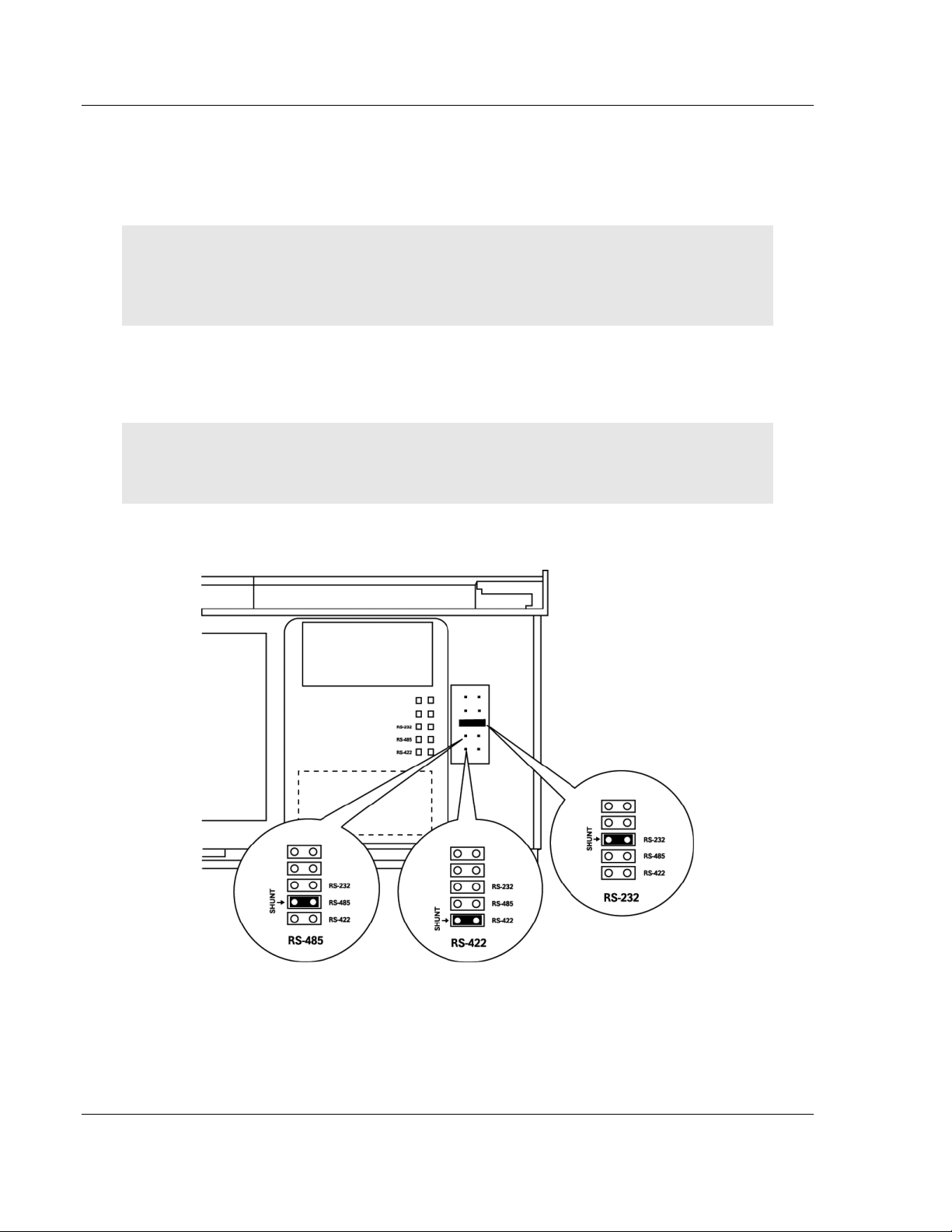
1.3 Setting Port 0 Configuration Jumpers
Before installing the module on the DIN-rail, you must set the jumpers for the
Port 0 application port.
Note: Ethernet-only ProLinx modules do not use the serial port jumper settings. The serial
configuration jumper settings on an Ethernet-only module have no effect.
Note: The presence of Port 0 depends on the specific combination of protocols in your ProLinx
module. If your module does not have a Port 0, the following jumper settings do not apply.
Port 0 is preconfigured for RS-232. You can move the port configuration jumper
on the back of the module to select RS-485 or RS-422.
Note: Some ProLinx modules do not correctly report the position of the port 0 jumper to the Port
Configuration page on the Config/Debug menu. In cases where the reported configuration differs
from the known jumper configuration, the physical configuration of the jumper is correct.
The following illustration shows the jumper positions for Port 0:
ProLinx 5000/6000 Series Module
Page 10 of 52 ProSoft Technology, Inc.
November 24, 2010
Page 11
BACnet ♦ ProLinx Gateway Start Here
BACnet/IP Client Edition 2 Protocol Manual
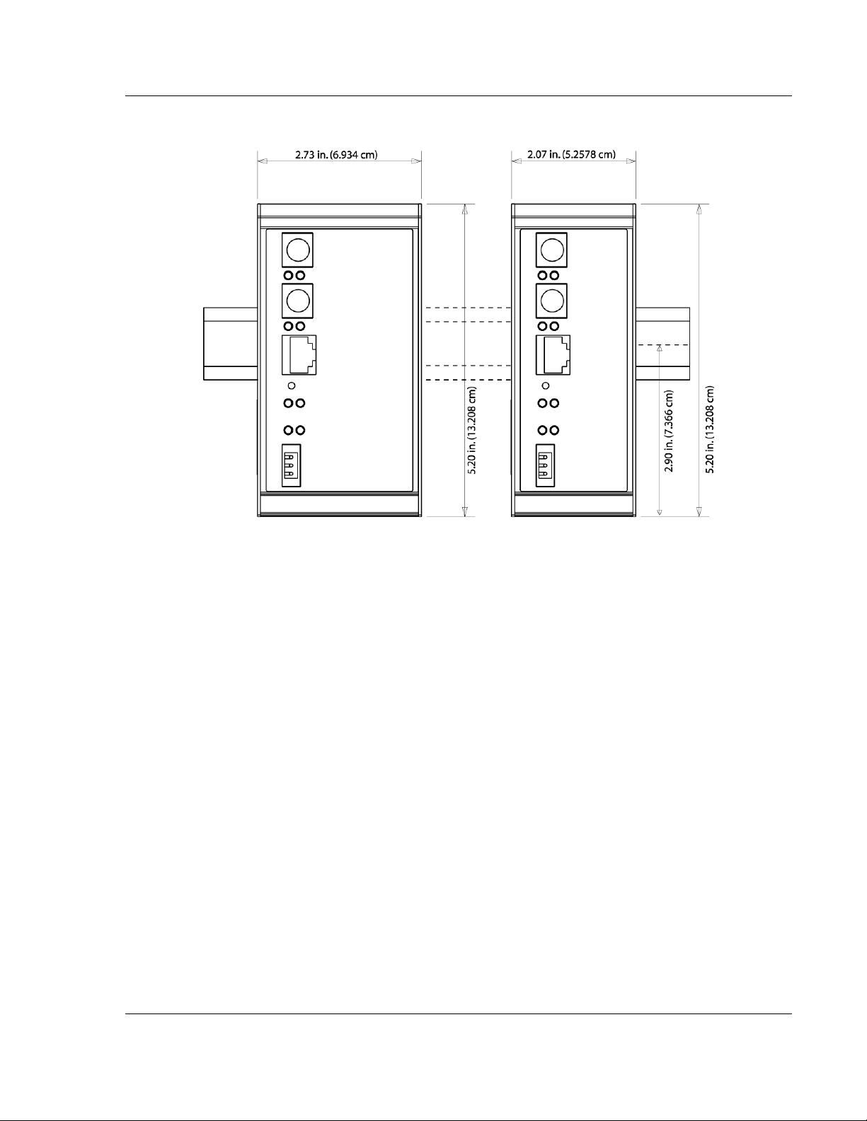
1.4 Mounting the Module on the DIN-rail
ProLinx 5000/6000 Series gateway
ProSoft Technology, Inc. Page 11 of 52
November 24, 2010
Page 12
Start Here BACnet ♦ ProLinx Gateway
Protocol Manual BACnet/IP Client Edition 2
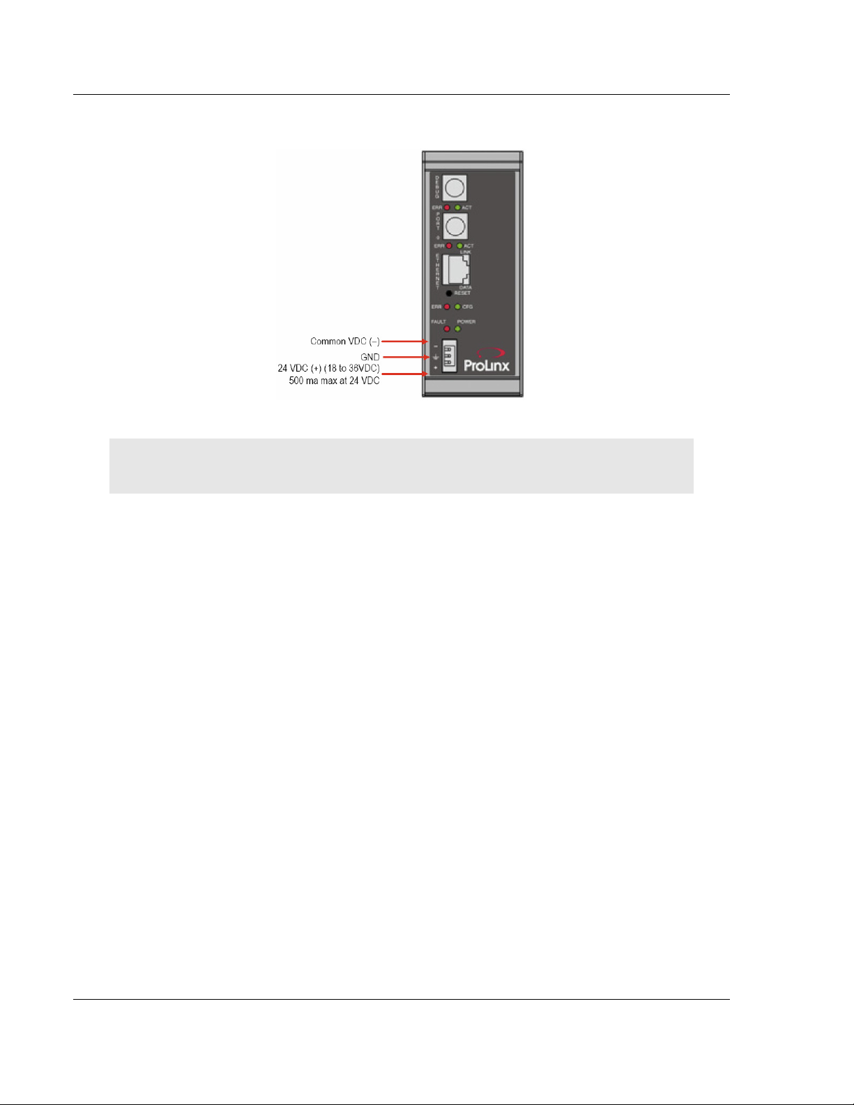
1.5 Connecting Power to the Unit
WARNING: Ensure that you do not reverse polarity when applying power to the gateway. This will
cause damage to the gateway’s power supply.
Page 12 of 52 ProSoft Technology, Inc.
November 24, 2010
Page 13
BACnet ♦ ProLinx Gateway Start Here
BACnet/IP Client Edition 2 Protocol Manual
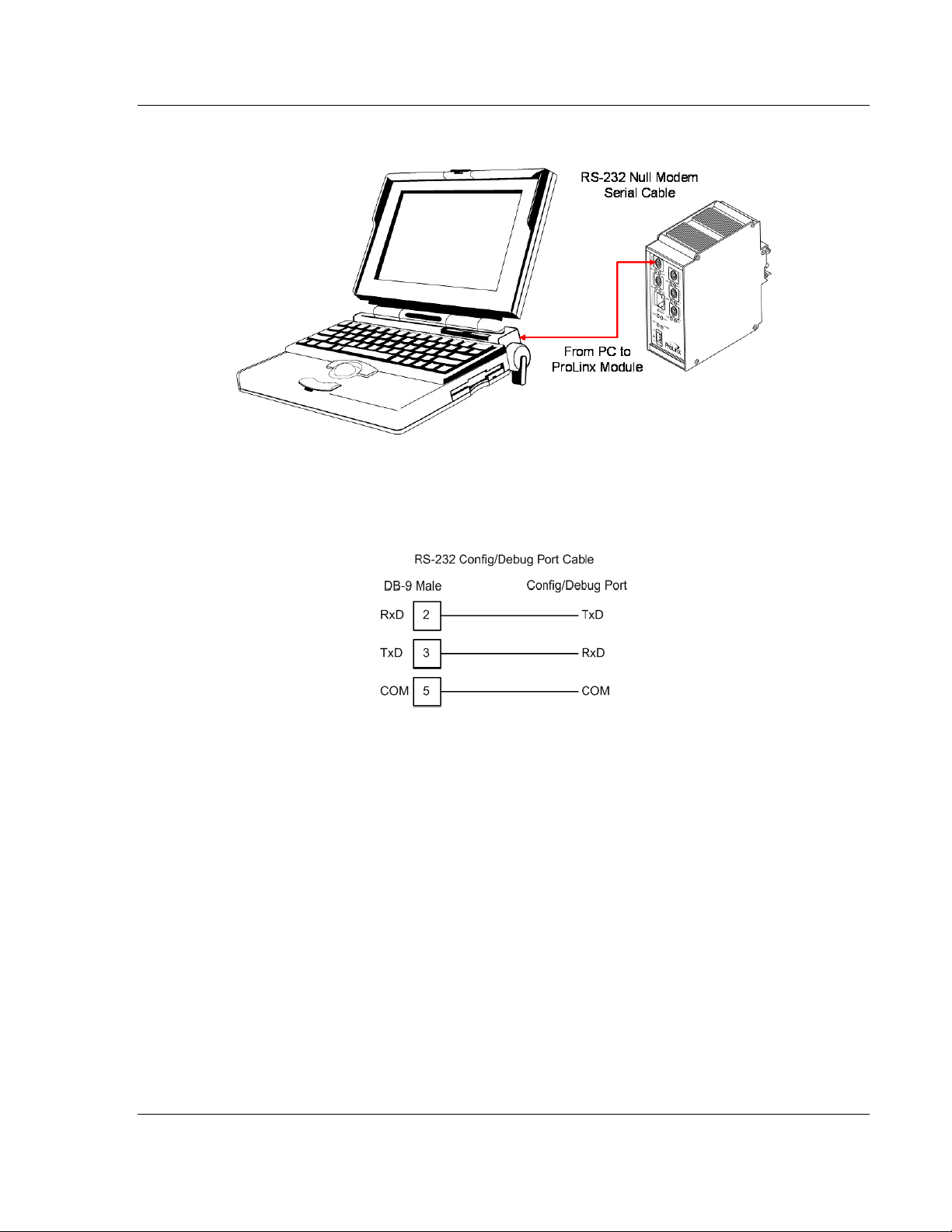
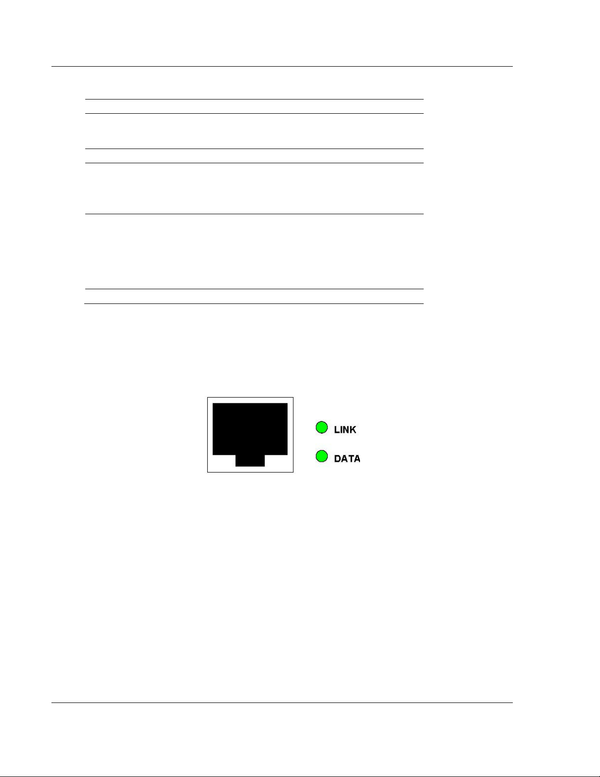
1.6 RS-232 Configuration Port Serial Connection
This port is physically a Mini-DIN connection. A Mini-DIN to DB-9 adapter cable
is included with the module. This port permits ProSoft Configuration Builder to
view configuration and status data in the module and to control the module. The
following illustration shows the pinout for communications on this port.
ProSoft Technology, Inc. Page 13 of 52
November 24, 2010
Page 14

Start Here BACnet ♦ ProLinx Gateway
Protocol Manual BACnet/IP Client Edition 2
1.7 Installing ProSoft Configuration Builder Software
You must install the ProSoft Configuration Builder (PCB) software to configure
the gateway. You can always get the newest version of ProSoft Configuration
Builder from the ProSoft Technology website.
Installing ProSoft Configuration Builder from the ProSoft website
1 Open your web browser and navigate to http://www.prosoft-
technology.com/pcb
2 Click the D
Configuration Builder.
3 Choose S
4 Save the file to your Windows Desktop, so that you can find it easily when
you have finished downloading.
5 When the download is complete, locate and open the file, and then follow the
instructions on your screen to install the program.
If you do not have access to the Internet, you can install ProSoft Configuration
Builder from the ProSoft Solutions Product CD-ROM, included in the package
with your gateway.
Installing ProSoft Configuration Builder from the Product CD-ROM
1 Insert the ProSoft Solutions Product CD-ROM into the CD-ROM drive of your
PC. Wait for the startup screen to appear.
2 On the startup screen, click P
Windows Explorer file tree window.
3 Click to open the U
and files you will need to set up and configure your gateway.
4 Double-click the S
PCB_*.
software on your PC. The information represented by the "*" character in the
file name is the PCB version number and, therefore, subject to change as
new versions of PCB are released.
OWNLOAD HERE
AVE
or S
AVE FILE
TILITIES
ETUP CONFIGURATION TOOL
EXE
file and follow the instructions on your screen to install the
link to download the latest version of ProSoft
when prompted.
RODUCT DOCUMENTATION
folder. This folder contains all of the applications
folder, double-click the
. This action opens a
Note: Many of the configuration and maintenance procedures use files and other utilities on the
CD-ROM. You may wish to copy the files from the Utilities folder on the CD-ROM to a convenient
location on your hard drive.
1.7.1 Using the Online Help
Most of the information needed to help you use ProSoft Configuration Builder is
provided in a Help System that is always available whenever you are running
ProSoft Configuration Builder. The Help System does not require an Internet
connection.
To view the help pages, start ProSoft Configuration Builder, open the H
menu, and then choose C
ONTENTS
.
Page 14 of 52 ProSoft Technology, Inc.
November 24, 2010
ELP
Page 15
BACnet ♦ ProLinx Gateway Functional Overview
BACnet/IP Client Edition 2 Protocol Manual
2 Functional Overview
In This Chapter
BACnet/IP Client ................................................................................... 16
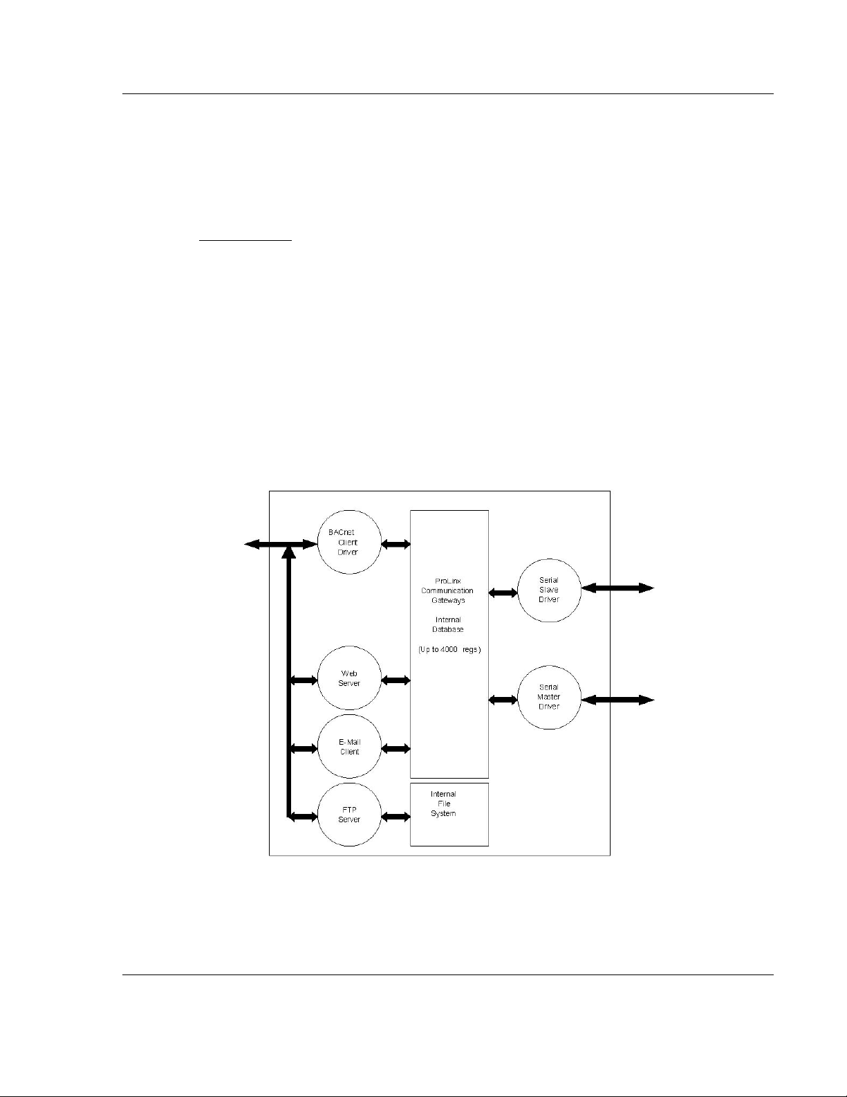
The ProLinx BACnet Client driver can be used to interface many different
protocols with Ethernet-enabled BACnet devices. The BACnet driver supports a
single UDP Client to interface with one or more devices that contain a BACnet
server.
The driver interfaces with a common internal database in the gateway. This
permits the sharing of data across many different networks. The following
illustration shows the functionality of the BACnet Client driver when interfaced
with serial communication based networks.
ProSoft Technology, Inc. Page 15 of 52
November 24, 2010
Page 16
Functional Overview BACnet ♦ ProLinx Gateway
Protocol Manual BACnet/IP Client Edition 2
2.1 BACnet/IP Client
General One UDP Client
Command List Support for 100 commands, each configurable for
Service Port
Function Code
Data Type
Point Count
The gateway supports a single independent Client on the IP network using the
UDP protocol to interface with processors or devices using a user constructed
command list of up to 100 entries. The gateway's internal database is used as
the source for write commands to the remote units. Data collected from the
remote units using read commands is placed in the gateway's database.
command, IP address, register to/from addressing
and word/bit count.
1 to 65535
12=Read Single Property
14=Read Multiple Properties
15=Write Single Property
16=Write Multiple Properties
0=Analog Input
1=Analog Output
2=Analog Value
3=Binary Input
4=Binary Output
5=Binary Value
1 to 25
2.1.1 Module Internal Database
The internal database is central to the functionality of the gateway. This database
is shared between all the drivers in the gateway and is used as a conduit to pass
information from one device on one network to one or more devices on another
network. This permits data from devices on one communication port to be viewed
and controlled by devices on another port.
In addition to data from the Client, status and error information generated by the
gateway can also be mapped into the internal database. Use this data to
determine the "health" of the gateway and to determine if commands are being
processed successfully.
Page 16 of 52 ProSoft Technology, Inc.
November 24, 2010
Page 17

BACnet ♦ ProLinx Gateway Functional Overview
BACnet/IP Client Edition 2 Protocol Manual
2.1.2 BACnet/IP Client Access to Database
The Client functionality automatically places data from a BACnet/IP device into
the gateway's internal database using read functions, and writes data from the
gateway's internal database to the remote unit. The Client driver generates the
message to the remote device using the gateway's user-constructed command
list. The command list defined in the user configuration determines what data is
to be transferred between the gateway and the remote units.
The following diagram describes the flow of data between the Client, the internal
database and the remote servers.
ProSoft Technology, Inc. Page 17 of 52
November 24, 2010
Page 18

Functional Overview BACnet ♦ ProLinx Gateway
Protocol Manual BACnet/IP Client Edition 2
Page 18 of 52 ProSoft Technology, Inc.
November 24, 2010
Page 19

BACnet ♦ ProLinx Gateway BACnet Protocol Configuration
BACnet/IP Client Edition 2 Protocol Manual
3 BACnet Protocol Configuration
In This Chapter
Configuring the Module ......................................................................... 20
BACnet Client 0 ..................................................................................... 25
BACnet Client 0 Commands .................................................................. 26
Ethernet Port Configuration - wattcp.cfg ................................................ 33
The following steps explain how to configure the BACnet/IP protocol using
ProSoft Configuration Builder.
ProSoft Technology, Inc. Page 19 of 52
November 24, 2010
Page 20

BACnet Protocol Configuration BACnet ♦ ProLinx Gateway
Protocol Manual BACnet/IP Client Edition 2
3.1 Configuring the Module
3.1.1 Adding a Module
To add a module to your project
1 Double-click the D
Module Type dialog box.
Note: ProLinx gateways always combine two or more protocols. The following illustration shows an
example ProLinx gateway with BACnet and one other protocol. Please choose the gateway in
ProSoft Configuration Builder that matches the combination of protocols in your ProLinx gateway.
EFAULT MODULE
icon in the left pane to open the Choose
2 In the Choose Module Type dialog box, select the module type.
Page 20 of 52 ProSoft Technology, Inc.
November 24, 2010
Page 21

BACnet ♦ ProLinx Gateway BACnet Protocol Configuration
BACnet/IP Client Edition 2 Protocol Manual
3.1.2 Module Entries
To configure module parameters
1 Click the [+] sign next to the module icon to expand module information.
2 Expand any icon in the list to view its configuration tags. Double-click a tag to
edit the configuration parameters.
ProSoft Technology, Inc. Page 21 of 52
November 24, 2010
Page 22
BACnet Protocol Configuration BACnet ♦ ProLinx Gateway
Protocol Manual BACnet/IP Client Edition 2
3 For parameter entries, select the parameter in the left pane and make your
changes in the right pane.
For command list and data map entries, click the A
item to the list. Click E
4 Click OK to save your changes.
DIT ROW
to edit the parameters.
DD ROW
button to add an
Page 22 of 52 ProSoft Technology, Inc.
November 24, 2010
Page 23

BACnet ♦ ProLinx Gateway BACnet Protocol Configuration
BACnet/IP Client Edition 2 Protocol Manual
3.1.3 Creating Optional Comment Entries
1 Click the [+] to the left of the icon to expand the module
comments.
2 Double-click the icon. The Edit - Module Comment dialog box
appears.
3 Enter your comment and click OK to save your changes.
3.1.4 Printing a Configuration File
1 Select the gateway icon, and then click the right mouse button to open a
shortcut menu.
2 On the shortcut menu, choose V
View Configuration window.
3 In the View Configuration window, open the F
This action opens the Print dialog box.
4 In the Print dialog box, choose the printer to use from the drop-down list,
select printing options, and then click OK.
IEW CONFIGURATION
ILE
menu, and choose P
. This action opens the
RINT.
ProSoft Technology, Inc. Page 23 of 52
November 24, 2010
Page 24

BACnet Protocol Configuration BACnet ♦ ProLinx Gateway
Protocol Manual BACnet/IP Client Edition 2
3.1.5 Downloading a File from PC to the Module
1 Verify that your PC is connected to the gateway with a null-modem serial
cable connected to the serial port on your PC and the serial port on the
gateway
2 Open the P
3 On the M
scans for communication ports on your PC. When the scan is complete, the
Download dialog box opens.
ROJECT
ODULE
menu, and then choose M
menu, choose D
OWNLOAD.
ODULE
.
Wait while ProSoft Configuration
4 Select the
5 Click the D
PORT
to use for the download.
OWNLOAD
button.
Page 24 of 52 ProSoft Technology, Inc.
November 24, 2010
Page 25

BACnet ♦ ProLinx Gateway BACnet Protocol Configuration
BACnet/IP Client Edition 2 Protocol Manual
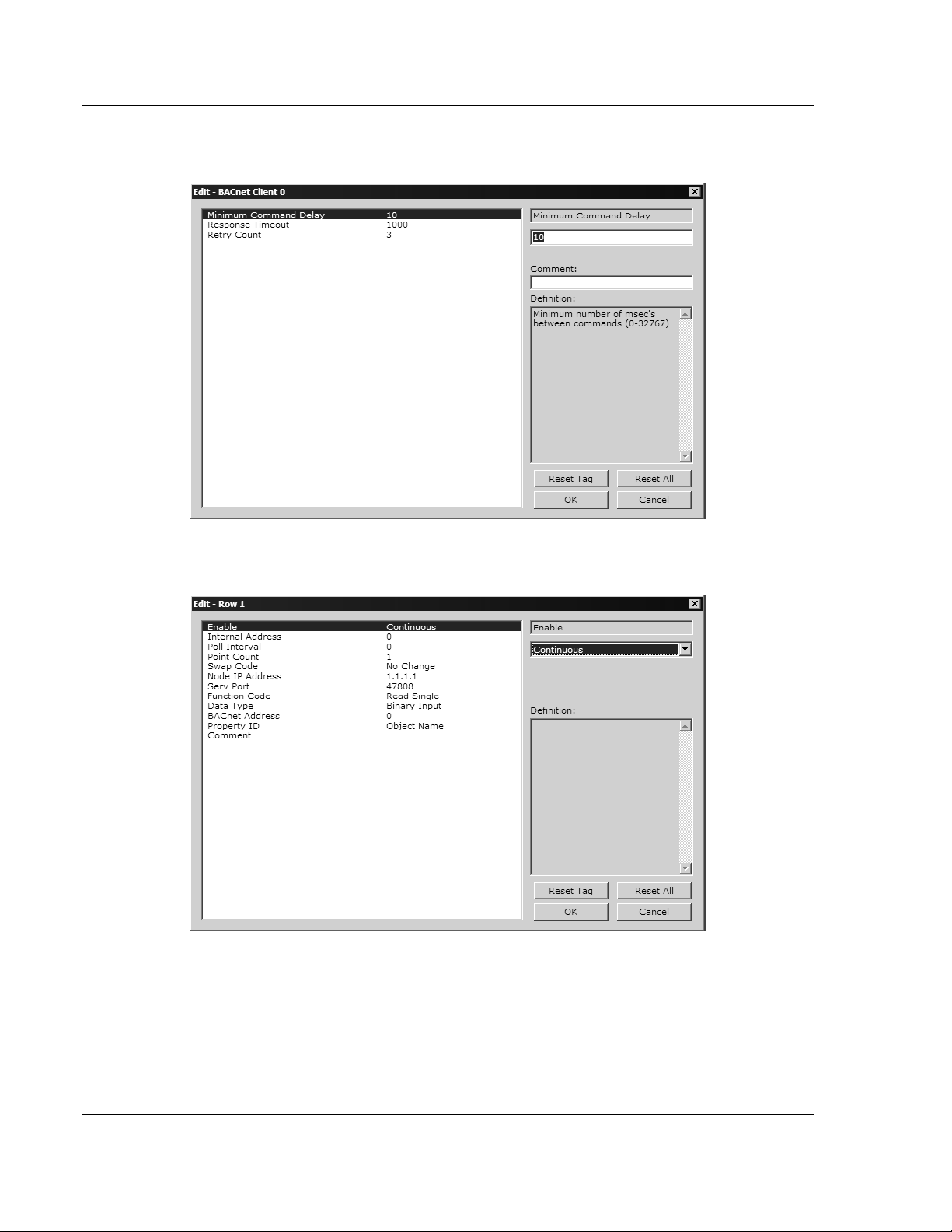
3.2 BACnet Client 0
The BACnet Client 0 section of the configuration specifies the parameters for the
BACnet Client to be emulated on the gateway. The command list for the Client is
entered in a separate section.
3.2.1 Minimum Command Delay
0 to 32767
This parameter specifies the number of milliseconds to wait between the initial
issuances of a command. It can be used to delay all commands sent to servers
to avoid "flooding" the network. This parameter does not affect retries of a
command, as they are issued when failure is recognized.
3.2.2 Response Timeout
0 to 65535 milliseconds
This is the time in milliseconds that a Client will wait before re-transmitting a
command if no response is received from the addressed server. The value to use
depends on the type of communication network used, and the expected
response time of the slowest device on the network.
3.2.3 Retry Count
0 to 10
This parameter specifies the number of times a command will be retried if it fails.
ProSoft Technology, Inc. Page 25 of 52
November 24, 2010
Page 26

BACnet Protocol Configuration BACnet ♦ ProLinx Gateway
Protocol Manual BACnet/IP Client Edition 2
3.3 BACnet Client 0 Commands
The BACnet Client 0 Commands section defines the BACnet commands to be
issued for data collection and control of the remote units on the UDP/IP network.
The gateway supports numerous commands to interface with many different
units and data types. For the commands to operate correctly, the server device
must be configured correctly. An incorrectly configured server is the primary
cause of user problems with the gateway.
3.3.1 Command List Overview
In order to interface the ProLinx gateway with BACnet Server devices, you must
construct a command list. The commands in the list specify the server device to
be addressed, the function to be performed (read or write), the data area in the
device to interface with, and the registers in the internal database to be
associated with the device data.
Up to 100 commands can be entered in the command list for the Client port. The
command list is processed from top (command #1) to bottom. A Poll Interval
parameter is associated with each command to specify a minimum delay time in
tenths of a second between issuances of the command. If the user specifies a
value of 10 for the parameter, the command will be executed no more frequently
than every one (1) second.
Page 26 of 52 ProSoft Technology, Inc.
November 24, 2010
Page 27

BACnet ♦ ProLinx Gateway BACnet Protocol Configuration
BACnet/IP Client Edition 2 Protocol Manual
Write commands have a special feature, as they can be set to execute only if the
data area associated with the write command changes. If the register data values
in the command have not changed since the command was last issued, the
command will not be executed. If the data in the command has changed since
the command was last issued, the command will be executed. Use of this feature
can lighten the load on the network. In order to implement it, set the Enable
parameter for the command to C
ONDITIONAL
. Care should be taken when using
this option, as the UDP protocol does not guarantee the delivery of each
message. Therefore, after the write message is executed and after its retry count
has expired, it will not be sent out again until the data changes in the gateway's
database. The remote device may never receive the write message. Because of
this problem, this option should only be utilized on networks where the message
is guaranteed to get through and be processed by the server.
The gateway supports numerous commands, allowing it to interface with a wide
variety of devices.
3.3.2 Commands Supported by the Gateway
The format of each command in the list is the same for all operations. The first
part of the record contains information relating to the communication gateway,
and the second part contains information required to interface with the BACnet
server device. The Client supports the two basic functions: read and write. Within
each of these, a single or multiple point function is also supported.
Care must be taken to configure the command list parameters to allow the
commands to interface with the server device and its database. The commands
will execute properly only if these parameters are set correctly.
ProSoft Technology, Inc. Page 27 of 52
November 24, 2010
Page 28

BACnet Protocol Configuration BACnet ♦ ProLinx Gateway
Protocol Manual BACnet/IP Client Edition 2
3.3.3 Command Entry Formats
The following table shows the structure of the configuration data necessary for
each of the supported commands.
Gateway Information Data ← → Device Information Data
Column # 1 2 3 4 5 6 7 8 9 10 11
Function
Code
FC 12 0/1 Property
FC 14 0/1 Property
FC 12 0/1 Property
FC 14 0/1 Property
FC 15 0/1/2 Property
FC 16 0/1/2 Property
FC 12 0/1 Property
FC 14 0/1 Property
FC 12 0/1 Property
FC 14 0/1 Property
FC 12 0/1 Property
FC 14 0/1 Property
FC 15 0/1/2 Property
FC 16 0/1/2 Property
FC 12 0/1 Property
FC 14 0/1 Property
Enable
Code
Internal
Address
Dependent
Dependent
Dependent
Dependent
Dependent
Dependent
Dependent
Dependent
Dependent
Dependent
Dependent
Dependent
Dependent
Dependent
Dependent
Dependent
Poll
Interval
Time
1/10 Sec Count Code xxx.xxx.xxx.xxx 47808 12 0 AI Point
1/10 Sec Count Code xxx.xxx.xxx.xxx 47808 14 0 AI Point
1/10 Sec Count Code xxx.xxx.xxx.xxx 47808 12 1 A0 Point
1/10 Sec Count Code xxx.xxx.xxx.xxx 47808 14 1 A0 Point
1/10 Sec Count Code xxx.xxx.xxx.xxx 47808 15 1 A0 Point
1/10 Sec Count Code xxx.xxx.xxx.xxx 47808 16 1 A0 Point
1/10 Sec Count Code xxx.xxx.xxx.xxx 47808 12 2 AI Point
1/10 Sec Count Code xxx.xxx.xxx.xxx 47808 14 2 AI Point
1/10 Sec Count 0 xxx.xxx.xxx.xxx 47808 12 3 BI Point
1/10 Sec Count 0 xxx.xxx.xxx.xxx 47808 14 3 BI Point
1/10 Sec Count 0 xxx.xxx.xxx.xxx 47808 12 4 B0 Point
1/10 Sec Count 0 xxx.xxx.xxx.xxx 47808 14 4 B0 Point
1/10 Sec Count 0 xxx.xxx.xxx.xxx 47808 15 4 B0 Point
1/10 Sec Count 0 xxx.xxx.xxx.xxx 47808 16 4 B0 Point
1/10 Sec Count 0 xxx.xxx.xxx.xxx 47808 12 5 BI Point
1/10 Sec Count 0 xxx.xxx.xxx.xxx 47808 14 5 BI Point
Point
Count
Swap
IP Address Service
Code
Port
BACnet
Function
Data
Type
BACnet
Address
Address
Address
Address
Address
Address
Address
Addres
Address
Address
Address
Address
Address
Address
Address
Address
Address
Propert
y
ID Code
ID Code
ID Code
ID Code
ID Code
ID Code
ID Code
ID Code
ID Code
ID Code
ID Code
ID Code
ID Code
ID Code
ID Code
ID Code
Page 28 of 52 ProSoft Technology, Inc.
November 24, 2010
Page 29

BACnet ♦ ProLinx Gateway BACnet Protocol Configuration
BACnet/IP Client Edition 2 Protocol Manual
The first part of the record is the Prolinx gateway information, and the second
part contains the information required to interface with the server device.
Parameter Value Description
Enable 0, 1 or 2 This field defines whether the command is to be executed and under what
conditions.
Value Description
0=D
ISABLED
The command is disabled and will not be executed in
the normal polling sequence.
1=C
ONTINUOUS
2=C
ONDITIONAL
Internal Address Dependent on
Property ID code
utilized
This parameter is used to specify the location in the gateway's internal
database to be associated with the command. For read operations, this
parameter sets the starting address of the area in the database where the data
received from the device will be placed. For write operations, it sets the starting
address of the area from which the data will be sourced. The Internal Address
is property dependent as listed in a following table (use the Property List to find
data size lengths for each property). Refer to the discussion contained in this
section for a further description of this field.
Poll Interval 0 to 65535 This parameter specifies the minimum interval for continuous command
execution (Enable = C
seconds. Therefore, if a value of 10 is entered for a command, the command
will execute no more frequently than every 1 second.
Point Count 1 to 25 This parameter specifies the number of points to be associated with the
command. This value should be set to 1 for function codes 12 and 15.
Swap Code 0, 1, 2 or 3 This parameter defines if the data received from the Server is to be ordered
differently than received from the Server device. This parameter is helpful when
dealing with floating-point or other multi-register values, as there is no standard
method of storage of these data types in Server devices. This parameter can
be set to order the register data received in an order useful by other
applications. The following table defines the values and their associated
operations:
Swap Code Description
0=NO C
1=W
ORD SWAP
2=W
ORD AND BYTE SWAP
3=B
YTE SWAP
Node IP Address xxx.xxx.xxx.xxx The IP address of the device being addressed by the command.
Service Port 1 to 65535 The Service Port address for most BACnet applications is 47808 (=0xBAC0).
Enter this value in decimal format. If the server requires a different service port
address (it is not compliant), enter the value required in this field.
Function Code 12, 14, 15 or 16 This field defines the function to be performed by the command.
Valid function codes used by the module are as follows: 12=R
P
ROPERTY
16=W
RITE MULTIPLE PROPERTIES
The command executes with each scan of the
command list if the Poll Interval is set to zero. If the Poll
Interval is set to a nonzero value, the command
executes when the interval timer expires.
The command executes only if the data associated with
the command changes. This value is valid only for write
commands.
ONTINUOUS
HANGE
No change is made in the byte ordering
). The parameter is entered in units of 0.1
The words are swapped
The words are swapped, then the bytes in
each word are swapped
The bytes in each word are swapped
, 14=R
EAD MULTIPLE PROPERTIES
, 15=W
RITE SINGLE PROPERTY
.
EAD SINGLE
and
ProSoft Technology, Inc. Page 29 of 52
November 24, 2010
Page 30

BACnet Protocol Configuration BACnet ♦ ProLinx Gateway
Protocol Manual BACnet/IP Client Edition 2
Parameter Value Description
Data Type 0, 1, 2, 3, 4 or 5 This field defines the data type to be interfaced with on the server device. The
Data Type Codes used by the module are as follows: 0=A
1=A
NALOG OUTPUT
5=B
INARY VALUE
BACnet Address Device Dependent This parameter specifies the starting point address for the selected data type in
the server device.
Property ID 0 to 65535 The Property ID is a value from 0 to 65535 (Present Value = 85 and Status
Flags = 111). Please refer to the remote device's documentation to determine
which property identification codes are supported. For write commands
(function codes 15 and 16), the property value is always set to 85 by the driver.
, 2=A
.
NALOG VALUE
, 3=B
INARY INPUT
NALOG INPUT
, 4=B
INARY OUTPUT
,
and
The following table lists the property identification codes used in the BACnet
protocol and supported by the driver.
Property
Code
75 Object Identifier 4-bytes R R R R
77 Object Name Character String R R R R
79 Object Type Byte (Enumerated) R R R R
85 Present Value 4-byte Real (AI/AO), Bit(BI/BO) R W R W
111 Status Flags Byte (Bit encoded) R R R R
36 Event State Byte (Enumerated) R R R R
81 Out-of-service Bit R R R R
117 Engineering units Byte (Enumerated) R R
69 Minimum Present Value 4-byte Real O O
65 Maximum Present Value 4-byte Real O O
106 Resolution 4-byte Real O O
118 Update Interval Unsigned O
22 COV Increment 4-byte Real O O
113 Time Delay Unsigned O O O O
17 Notification Class Unsigned O O O O
45 High-Limit 4-byte Real O O
59 Low-Limit 4-byte Real O O
25 Deadband 4-byte Real O O
52 Limit Enable Byte (Bit encoded) O O
35 Event Enable Byte (Bit encoded) O O O O
0 Acked Transitions Byte (Bit encoded) O O O O
72 Notify Type Byte (Enumerated) O O O O
28 Description Character String O O O O
31 Device Type Character String O O O O
103 Reliability Byte (Enumerated) O O O O
104 Relinquish Default Byte (Enumerated)
84 Polarity Byte (Enumerated)
Description Length Data Type
AI AO BI BO
R
R
R R
Page 30 of 52 ProSoft Technology, Inc.
November 24, 2010
Page 31

BACnet ♦ ProLinx Gateway BACnet Protocol Configuration
BACnet/IP Client Edition 2 Protocol Manual
Property
Code
46 Inactive Text Character String
4 Active Text Character String
15 Change of State Count Unsigned
33 Elapsed Active Time Unsigned32
6 Alarm Value Byte (Enumerated)
66 Minimum Off Time Unsigned32
67 Minimum On Time Unsigned32
40 Feedback Value Byte (Enumerated)
R=Read-only required by all devices.
W=Read/Write required by all devices.
O=Read-only and is optional for device.
If cell is blank, the property is not supported for the data type.
Description Length Data Type
AI AO BI BO
O O
O O
O O
O O
O
O
O
O
Please review the BACnet Protocol Specification for a complete discussion of
each of the property identification codes and for the definition of the enumerated
values. Care must be taken when designing the application to make sure
command message data does not overlap. Consult the server device
documentation to verify that the data type, point number, function and property
identification code are supported.
The Property ID column determines the Internal Address field. Use the previously
provided Property ID table to determine the data type used with the point.
Data Length Internal Address Offset
Bit Bit offset from start of database (packed data) (0 to 64000) - Each data point uses a single bit in
the database.
Byte Byte offset from start of database (0 to 7999) - Each data point uses a single byte in the database.
Unsigned (Byte offset)*2 from start of database (0 to 3999) - Each data point uses two bytes (one word
register) in the database.
Unsigned32 (Byte offset)*4 from start of database (0 to 2999) - Each data point uses four bytes (two word
registers) in the database.
4-Bytes (Byte offset)*4 from start of database (0 to 2999) - Each data point uses four bytes (two word
registers) in the database.
4-Byte Real (Byte offset)*4 from start of database (0 to 2999) - Each data point uses four bytes (two word
registers) in the database.
Character String Byte offset from start of database (0 to 7999) - Each data point uses the number of bytes required
to store the character string. Care should be used with these property types to make sure the
database of one point does not overlap that of another.
NOTES
The length of the Character String type is variable and may cause for a read operation to
overwrite other data if not enough space is allocated for each string.
The binary input present value (property 85) returned from a read statement is placed at the bit
offset in the internal address.
The bit offset in the internal database is used for the binary output read and write operations.
ProSoft Technology, Inc. Page 31 of 52
November 24, 2010
Page 32

BACnet Protocol Configuration BACnet ♦ ProLinx Gateway
Protocol Manual BACnet/IP Client Edition 2
Command list example:
[BACnet Client 0 Commands]
#
# This section contains the commands that will be issued by the BACnet client
# service. Each valid command will be issued to the unit specified using the
# command data entered by the user.
#
# LOCATION :
# DATE :
# CONFIGURED BY:
# MODIFIED :
#
# 1 2 3 4 5 6 7 8 9 10 11
# DB Poll Reg Swap Serv Func Data Point Prop
#Enab Addr Delay Count Code Node IP Address Port Code Type Addr Code
START
0 305 0 7 1 192.168.0.110 47808 14 1 1 85
0 1500 0 7 1 192.168.0.110 47808 16 1 1 85
0 200 0 1 1 192.168.0.110 47808 12 0 1 85
0 205 0 24 1 192.168.0.110 47808 14 0 1 85
0 300 0 1 1 192.168.0.110 47808 12 1 1 85
0 315 0 7 3 192.168.0.110 47808 14 1 1 69
0 325 0 7 3 192.168.0.110 47808 14 1 1 65
0 800 0 1 0 192.168.0.110 47808 12 3 1 85
0 816 0 10 0 192.168.0.110 47808 14 3 1 85
0 832 0 1 0 192.168.0.110 47808 12 4 1 85
0 848 0 6 0 192.168.0.110 47808 14 4 1 85
0 1600 0 1 0 192.168.0.110 47808 15 4 2 85
0 1600 0 4 0 192.168.0.110 47808 16 4 3 85
0 864 0 4 0 192.168.0.110 47808 14 4 3 85
END
Page 32 of 52 ProSoft Technology, Inc.
November 24, 2010
Page 33

BACnet ♦ ProLinx Gateway BACnet Protocol Configuration
BACnet/IP Client Edition 2 Protocol Manual
3.4 Ethernet Port Configuration - wattcp.cfg
The wattcp.cfg file must be set up properly in order to use a TCP/IP network
connection. The ProLinx Reference Guide provides detailed information on
setting up this file, as well as how to load it to ProLinx modules.
ProSoft Technology, Inc. Page 33 of 52
November 24, 2010
Page 34

BACnet Protocol Configuration BACnet ♦ ProLinx Gateway
Protocol Manual BACnet/IP Client Edition 2
Page 34 of 52 ProSoft Technology, Inc.
November 24, 2010
Page 35

BACnet ♦ ProLinx Gateway Client Error/Status Data
BACnet/IP Client Edition 2 Protocol Manual
4 Client Error/Status Data
In This Chapter
Client Error/Status Data......................................................................... 36
BACnet Client Command List Error Data .............................................. 37
Error Codes ........................................................................................... 38
The second and most thorough troubleshooting method for debugging the
operation of the BACnet/IP driver (and the module in general) is the powerful
Debug port on the module which provides much more complete access to the
internal operation and status of the module. Accessing the Debug capabilities of
the module is accomplished easily by connecting a PC to the Debug port and
loading a terminal program such as ProSoft Configuration Builder or
HyperTerminal.
ProSoft Technology, Inc. Page 35 of 52
November 24, 2010
Page 36

Client Error/Status Data BACnet ♦ ProLinx Gateway
Protocol Manual BACnet/IP Client Edition 2
4.1 Client Error/Status Data
The Client connection Error and Status Data areas are discussed in this section
The error/status data table is located at a virtual address assigned by ProLinx. If
this data is moved to the gateway's database using the gateway's data mapping
feature, it will be available to the other protocol supported on the gateway. If it is
not mapped into the gateway's database, the data will only be available through
the Configuration/Debug Port.
The data area is initialized with zeros whenever the module is initialized. This
occurs during a cold-start (power-on), reset (reset push-button pressed) or a
warm-boot operation (commanded or loading of new configuration).
Note: The ProLinx Reference Guide contains detailed information on accessing the contents of the
following registers.
4.1.1 BACnet Client 0 Status
The following table lists the data areas that can be mapped from the virtual
addresses into the gateway's internal database.
Status Register Description
12300 Command Request Count
12301 Command Response Count
12302 Command Error Count
12303 Number of Request Packets
12304
12305 Errors Sent
12306 Errors Received
12307 Configuration Error Word
12308 Current Error
12309 Last Error
12310 to 12409 Command List Errors (1 word register for each command)
12410 to 12499 No Valid Data
Number of Response Packets
Page 36 of 52 ProSoft Technology, Inc.
November 24, 2010
Page 37

BACnet ♦ ProLinx Gateway Client Error/Status Data
BACnet/IP Client Edition 2 Protocol Manual
4.2 BACnet Client Command List Error Data
Each command in the command list for the BACnet Client has a reserved word
value for a status/error code. This error data list can be read using the
Debug/Config Port and can be placed in the gateway's internal database.
The first word in the register location defined contains the status/error code for
the first command in the Client's command list. Each successive word in the
command error list is associated with the next command in the list. Therefore, the
size of the data area depends on the number of commands defined. The
structure of the data area is displayed in the following tables.
4.2.1 BACnet Client 0 (Command List Error Data)
Internal Database
Address
12310 0 Command #0 Error Status
12311 1 Command #1 Error Status
12312 2 Command #2 Error Status
12313 3 Command #3 Error Status
12314 4 Command #4 Error Status
. .
. .
. .
12407 97 Command #97 Error Status
12408 98 Command #98 Error Status
12409 99 Command #99 Error Status
Offset Description
Note that the values in the Command List Error Status tables are initialized to
zero (0) at power-up, cold boot and during warm boot. Refer to the following topic
containing Error Codes to interpret the status/error codes present in the data
area.
ProSoft Technology, Inc. Page 37 of 52
November 24, 2010
Page 38

Client Error/Status Data BACnet ♦ ProLinx Gateway
Protocol Manual BACnet/IP Client Edition 2
4.3 Error Codes
The gateway's error codes are listed in this section. Error codes returned from
the command list process are stored in the command list error memory region. A
word is allocated for each command in the memory area.
Use the error codes returned for each command in the list to determine the
success or failure of the command. If the command fails, use the error code to
determine the cause of failure.
Note: The gateway-specific error codes are returned from within the gateway and never from an
attached server device.
4.3.1 BACnet Client Protocol Error Codes
These are error codes that are part of the BACnet protocol or are extended
codes unique to this gateway. The standard BACnet error codes can be found in
the BACnet Protocol Standard, section 21.
Standard BACnet Errors
Error Word
MSB LSB Group Description
0x00 E-Code* Device Error The LSB contains the error code for this device error.
0x01 E-Code* Object Error The LSB contains the error code for this object error.
0x02 E-Code* Property
0x03 E-Code* Resource
0x04 E-Code* Security
0x05 E-Code* Service
0x06 E-Code* VT Error The LSB contains the error code for this virtual terminal error.
0x40 A-Code* Abort
0X80 R-Code* Reject
E-Code*: Refer to the BACnet specification Section 21 for a complete listing of the error codes.
A-Code*: Refer to the BACnet specification Section 21 for a complete listing of the abort codes.
R-Code*: Refer to the BACnet specification Section 21 for a complete listing of the reject reason
codes.
Error
Error
Error
Error
Message
Message
The LSB contains the error code for this property error.
The LSB contains the error code for this resource error.
The LSB contains the error code for this security error.
The LSB contains the error code for this service error.
Response is an abort message. The abort code is stored in the
LSB.
Response is a reject message. The rejection code is stored in
the LSB.
Page 38 of 52 ProSoft Technology, Inc.
November 24, 2010
Page 39

BACnet ♦ ProLinx Gateway Client Error/Status Data
BACnet/IP Client Edition 2 Protocol Manual
4.3.2 Gateway-specific Error Codes
The following error codes are specific to the gateway's BACnet driver.
Parsing Errors
Error Word
MSB LSB Group Description
0x20 0x0x Context
Tag Error
0x20 0x1x Context
Tag Error
0x20 0x2x Context
Tag Error
0x20 0x3x Context
Tag Error
0x20 0x4x Context
Tag Error
0x20 0x5x Context
Tag Error
0x20 0x04 Parse
Error
0x20 0x08 Parse
Error
0x20 0x0A Parse
Error
0x20 0x0B Parse
Error
0x20 0x0C Parse
Error
Error in the open or close tag for tag level 0 or the tag is missing.
Error in the open or close tag for tag level 1 or the tag is missing.
Error in the open or close tag for tag level 2 or the tag is missing.
Error in the open or close tag for tag level 3 or the tag is missing.
Error in the open or close tag for tag level 4 or the tag is missing.
Error in the open or close tag for tag level 5 or the tag is missing.
Error found when parsing application data type 0x04. The most likely
cause is that the length in the application tag was not set to a value
of four.
Error found when parsing application data type 0x05. The most likely
cause is that the length in the application tag was not set to a value
of eight.
Error found when parsing application data type 0x0A. The most likely
cause is that the length in the application tag was not set to a value
of four.
Error found when parsing application data type 0x0B. The most likely
cause is that the length in the application tag was not set to a value
of four.
Error found when parsing application data type 0x0C. The most likely
cause is that the length in the application tag was not set to a value
of four.
Network Errors
Error Word
MSB LSB Group Description
0xFF 0xDC Socket Response timeout after message poll. The server did not respond to
the request in the user set response timeout period.
0xFF 0xDE Socket Could not allocate memory area for the UDP socket
0xFF 0xDF Socket Failed to open UDP socket to selected server before transmitting a
request message.
ProSoft Technology, Inc. Page 39 of 52
November 24, 2010
Page 40

Client Error/Status Data BACnet ♦ ProLinx Gateway
Protocol Manual BACnet/IP Client Edition 2
Command List Parsing
Error Word
MSB LSB Group Description
0xFF 0x01 Command
Param
0xFF 0x02 Command
Param
0xFF 0x03 Command
Param
0xFF 0x04 Command
Param
0xFF 0x05 Command
Param
0xFF 0x06 Command
Param
0xFF 0x07 Command
Param
Error while reading in a command. Not enough parameters are
present in the current command record to construct a command.
Invalid type code entered for the enable field. Only values of 0 to
2 are accepted.
Count value in command set to zero. This parameter must be set
to a value greater than or equal to 1 and less than 25.
Invalid swap code entered for command. Values of 0 to 3 are only
those accepted by the program.
Invalid function code entered. This parameter must have one of
the following values: 12, 14, 15 or 16.
Invalid datatype selected for the command. This parameter must
be set to one of the following values: 0=analog input, 1=analog
output, 3=binary input or 4=binary output.
Invalid property value for the command. Refer to the property list
for all available properties supported by the program. This does
not imply that all servers will contain this property for every object
type.
Page 40 of 52 ProSoft Technology, Inc.
November 24, 2010
Page 41

BACnet ♦ ProLinx Gateway Reference
BACnet/IP Client Edition 2 Protocol Manual
5 Reference
In This Chapter
Command Configuration Form .............................................................. 42
ProSoft Technology, Inc. Page 41 of 52
November 24, 2010
Page 42

Reference BACnet ♦ ProLinx Gateway
Protocol Manual BACnet/IP Client Edition 2
5.1 Command Configuration Form
This section contains a form that can be used to design the command list for an
application.
BACnet Command List Form
Gateway Information Data ← → Device Information Data
1 2 3 4 5 6 7 8 9 10 11
Enable
Code
Page 42 of 52 ProSoft Technology, Inc.
November 24, 2010
Internal
Address
Poll
Interval
Time
Point
Count
Swap
Code
IP
Addres
s
Servic
e Port
BACnet
Function
Data
Type
BACnet
Address
Propert
y
Page 43

BACnet ♦ ProLinx Gateway Support, Service & Warranty
BACnet/IP Client Edition 2 Protocol Manual
6 Support, Service & Warranty
In This Chapter
Contacting Technical Support ............................................................... 43
Return Material Authorization (RMA) Policies and Conditions ............... 45
LIMITED WARRANTY ........................................................................... 47
Contacting Technical Support
ProSoft Technology, Inc. (ProSoft) is committed to providing the most efficient
and effective support possible. Before calling, please gather the following
information to assist in expediting this process:
1 Product Version Number
2 System architecture
3 Network details
If the issue is hardware related, we will also need information regarding:
1 Module configuration and associated ladder files, if any
2 Module operation and any unusual behavior
3 Configuration/Debug status information
4 LED patterns
5 Details about the serial, Ethernet or fieldbus devices interfaced to the module,
if any.
Note: For technical support calls within the United States, an after-hours answering system allows
24-hour/7-days-a-week pager access to one of our qualified Technical and/or Application Support
Engineers. Detailed contact information for all our worldwide locations is available on the following
page.
ProSoft Technology, Inc. Page 43 of 52
November 24, 2010
Page 44

Support, Service & Warranty BACnet ♦ ProLinx Gateway
Protocol Manual BACnet/IP Client Edition 2
Internet
Web Site: www.prosoft-technology.com/support
E-mail address: support@prosoft-technology.com
Asia Pacific
(location in Malaysia)
Asia Pacific
(location in China)
Europe
(location in Toulouse,
France)
Europe
(location in Dubai, UAE)
Tel: +603.7724.2080, E-mail: asiapc@prosoft-technology.com
Languages spoken include: Chinese, English
Tel: +86.21.5187.7337 x888, E-mail: asiapc@prosoft-technology.com
Languages spoken include: Chinese, English
Tel: +33 (0) 5.34.36.87.20,
E-mail: support.EMEA@prosoft-technology.com
Languages spoken include: French, English
Tel: +971-4-214-6911,
E-mail: mea@prosoft-technology.com
Languages spoken include: English, Hindi
North America
(location in California)
Tel: +1.661.716.5100,
E-mail: support@prosoft-technology.com
Languages spoken include: English, Spanish
Latin America
(Oficina Regional)
Tel: +1-281-2989109,
E-Mail: latinam@prosoft-technology.com
Languages spoken include: Spanish, English
Latin America
(location in Puebla, Mexico)
Tel: +52-222-3-99-6565,
E-mail: soporte@prosoft-technology.com
Languages spoken include: Spanish
Brasil
(location in Sao Paulo)
Tel: +55-11-5083-3776,
E-mail: brasil@prosoft-technology.com
Languages spoken include: Portuguese, English
Page 44 of 52 ProSoft Technology, Inc.
November 24, 2010
Page 45

BACnet ♦ ProLinx Gateway Support, Service & Warranty
BACnet/IP Client Edition 2 Protocol Manual
6.1 Return Material Authorization (RMA) Policies and Conditions
The following Return Material Authorization (RMA) Policies and Conditions
(collectively, "RMA Policies") apply to any returned product. These RMA Policies
are subject to change by ProSoft Technology, Inc., without notice. For warranty
information, see Limited Warranty (page 47). In the event of any inconsistency
between the RMA Policies and the Warranty, the Warranty shall govern.
6.1.1 Returning Any Product
a) In order to return a Product for repair, exchange, or otherwise, the
Customer must obtain a Return Material Authorization (RMA) number
from ProSoft Technology and comply with ProSoft Technology shipping
instructions.
b) In the event that the Customer experiences a problem with the Product for
any reason, Customer should contact ProSoft Technical Support at one of
the telephone numbers listed above (page 43). A Technical Support
Engineer will request that you perform several tests in an attempt to
isolate the problem. If after completing these tests, the Product is found to
be the source of the problem, we will issue an RMA.
c) All returned Products must be shipped freight prepaid, in the original
shipping container or equivalent, to the location specified by ProSoft
Technology, and be accompanied by proof of purchase and receipt date.
The RMA number is to be prominently marked on the outside of the
shipping box. Customer agrees to insure the Product or assume the risk
of loss or damage in transit. Products shipped to ProSoft Technology
using a shipment method other than that specified by ProSoft Technology,
or shipped without an RMA number will be returned to the Customer,
freight collect. Contact ProSoft Technical Support for further information.
d) A 10% restocking fee applies to all warranty credit returns, whereby a
Customer has an application change, ordered too many, does not need,
etc. Returns for credit require that all accessory parts included in the
original box (i.e.; antennas, cables) be returned. Failure to return these
items will result in a deduction from the total credit due for each missing
item.
ProSoft Technology, Inc. Page 45 of 52
November 24, 2010
Page 46

Support, Service & Warranty BACnet ♦ ProLinx Gateway
Protocol Manual BACnet/IP Client Edition 2
6.1.2 Returning Units Under Warranty
A Technical Support Engineer must approve the return of Product under ProSoft
Technology’s Warranty:
a) A replacement module will be shipped and invoiced. A purchase order will
be required.
b) Credit for a product under warranty will be issued upon receipt of
authorized product by ProSoft Technology at designated location
referenced on the Return Material Authorization
i. If a defect is found and is determined to be customer generated, or if
the defect is otherwise not covered by ProSoft Technology s warranty,
there will be no credit given. Customer will be contacted and can
request module be returned at their expense;
ii. If defect is customer generated and is repairable, customer can
authorize ProSoft Technology to repair the unit by providing a
purchase order for 30% of the current list price plus freight charges,
duties and taxes as applicable.
6.1.3 Returning Units Out of Warranty
a) Customer sends unit in for evaluation to location specified by ProSoft
Technology, freight prepaid.
b) If no defect is found, Customer will be charged the equivalent of $100
USD, plus freight charges, duties and taxes as applicable. A new
purchase order will be required.
c) If unit is repaired, charge to Customer will be 30% of current list price
(USD) plus freight charges, duties and taxes as applicable. A new
purchase order will be required or authorization to use the purchase order
submitted for evaluation fee.
The following is a list of non-repairable units:
o
3150 - All
o
3750
o
3600 - All
o
3700
o
3170 - All
o
3250
o
1560 - Can be repaired, only if defect is the power supply
o
1550 - Can be repaired, only if defect is the power supply
o
3350
o
3300
o
1500 - All
Page 46 of 52 ProSoft Technology, Inc.
November 24, 2010
Page 47

BACnet ♦ ProLinx Gateway Support, Service & Warranty
BACnet/IP Client Edition 2 Protocol Manual
6.2 LIMITED WARRANTY
This Limited Warranty ("Warranty") governs all sales of hardware, software, and
other products (collectively, "Product") manufactured and/or offered for sale by
ProSoft Technology, Incorporated (ProSoft), and all related services provided by
ProSoft, including maintenance, repair, warranty exchange, and service
programs (collectively, "Services"). By purchasing or using the Product or
Services, the individual or entity purchasing or using the Product or Services
("Customer") agrees to all of the terms and provisions (collectively, the "Terms")
of this Limited Warranty. All sales of software or other intellectual property are, in
addition, subject to any license agreement accompanying such software or other
intellectual property.
6.2.1 What Is Covered By This Warranty
a) Warranty On New Products: ProSoft warrants, to the original purchaser,
that the Product that is the subject of the sale will (1) conform to and
perform in accordance with published specifications prepared, approved
and issued by ProSoft, and (2) will be free from defects in material or
workmanship; provided these warranties only cover Product that is sold as
new. This Warranty expires three (3) years from the date of shipment for
Product purchased on or after January 1st, 2008, or one (1) year from the
date of shipment for Product purchased before January 1st, 2008 (the
"Warranty Period"). If the Customer discovers within the Warranty Period
a failure of the Product to conform to specifications, or a defect in material
or workmanship of the Product, the Customer must promptly notify
ProSoft by fax, email or telephone. In no event may that notification be
received by ProSoft later than 39 months from date of original shipment.
Within a reasonable time after notification, ProSoft will correct any failure
of the Product to conform to specifications or any defect in material or
workmanship of the Product, with either new or remanufactured
replacement parts. ProSoft reserves the right, and at its sole discretion,
may replace unrepairable units with new or remanufactured equipment.
All replacement units will be covered under warranty for the 3 year period
commencing from the date of original equipment purchase, not the date of
shipment of the replacement unit. Such repair, including both parts and
labor, will be performed at ProSoft’s expense. All warranty service will be
performed at service centers designated by ProSoft.
b) Warranty On Services: Materials and labor performed by ProSoft to repair
a verified malfunction or defect are warranteed in the terms specified
above for new Product, provided said warranty will be for the period
remaining on the original new equipment warranty or, if the original
warranty is no longer in effect, for a period of 90 days from the date of
repair.
ProSoft Technology, Inc. Page 47 of 52
November 24, 2010
Page 48

Support, Service & Warranty BACnet ♦ ProLinx Gateway
Protocol Manual BACnet/IP Client Edition 2
6.2.2 What Is Not Covered By This Warranty
a) ProSoft makes no representation or warranty, expressed or implied, that
the operation of software purchased from ProSoft will be uninterrupted or
error free or that the functions contained in the software will meet or
satisfy the purchaser’s intended use or requirements; the Customer
assumes complete responsibility for decisions made or actions taken
based on information obtained using ProSoft software.
b) This Warranty does not cover the failure of the Product to perform
specified functions, or any other non-conformance, defects, losses or
damages caused by or attributable to any of the following: (i) shipping; (ii)
improper installation or other failure of Customer to adhere to ProSoft’s
specifications or instructions; (iii) unauthorized repair or maintenance; (iv)
attachments, equipment, options, parts, software, or user-created
programming (including, but not limited to, programs developed with any
IEC 61131-3, "C" or any variant of "C" programming languages) not
furnished by ProSoft; (v) use of the Product for purposes other than those
for which it was designed; (vi) any other abuse, misapplication, neglect or
misuse by the Customer; (vii) accident, improper testing or causes
external to the Product such as, but not limited to, exposure to extremes
of temperature or humidity, power failure or power surges; or (viii)
disasters such as fire, flood, earthquake, wind and lightning.
c) The information in this Agreement is subject to change without notice.
ProSoft shall not be liable for technical or editorial errors or omissions
made herein; nor for incidental or consequential damages resulting from
the furnishing, performance or use of this material. The user guide
included with your original product purchase from ProSoft contains
information protected by copyright. No part of the guide may be duplicated
or reproduced in any form without prior written consent from ProSoft.
6.2.3 Disclaimer Regarding High Risk Activities
Product manufactured or supplied by ProSoft is not fault tolerant and is not
designed, manufactured or intended for use in hazardous environments requiring
fail-safe performance including and without limitation: the operation of nuclear
facilities, aircraft navigation of communication systems, air traffic control, direct
life support machines or weapons systems in which the failure of the product
could lead directly or indirectly to death, personal injury or severe physical or
environmental damage (collectively, "high risk activities"). ProSoft specifically
disclaims any express or implied warranty of fitness for high risk activities.
Page 48 of 52 ProSoft Technology, Inc.
November 24, 2010
Page 49

BACnet ♦ ProLinx Gateway Support, Service & Warranty
BACnet/IP Client Edition 2 Protocol Manual
6.2.4 Intellectual Property Indemnity
Buyer shall indemnify and hold harmless ProSoft and its employees from and
against all liabilities, losses, claims, costs and expenses (including attorney’s
fees and expenses) related to any claim, investigation, litigation or proceeding
(whether or not ProSoft is a party) which arises or is alleged to arise from Buyer’s
acts or omissions under these Terms or in any way with respect to the Products.
Without limiting the foregoing, Buyer (at its own expense) shall indemnify and
hold harmless ProSoft and defend or settle any action brought against such
Companies to the extent based on a claim that any Product made to Buyer
specifications infringed intellectual property rights of another party. ProSoft
makes no warranty that the product is or will be delivered free of any person’s
claiming of patent, trademark, or similar infringement. The Buyer assumes all
risks (including the risk of suit) that the product or any use of the product will
infringe existing or subsequently issued patents, trademarks, or copyrights.
a) Any documentation included with Product purchased from ProSoft is
protected by copyright and may not be duplicated or reproduced in any
form without prior written consent from ProSoft.
b) ProSoft’s technical specifications and documentation that are included
with the Product are subject to editing and modification without notice.
c) Transfer of title shall not operate to convey to Customer any right to make,
or have made, any Product supplied by ProSoft.
d) Customer is granted no right or license to use any software or other
intellectual property in any manner or for any purpose not expressly
permitted by any license agreement accompanying such software or other
intellectual property.
e) Customer agrees that it shall not, and shall not authorize others to, copy
software provided by ProSoft (except as expressly permitted in any
license agreement accompanying such software); transfer software to a
third party separately from the Product; modify, alter, translate, decode,
decompile, disassemble, reverse-engineer or otherwise attempt to derive
the source code of the software or create derivative works based on the
software; export the software or underlying technology in contravention of
applicable US and international export laws and regulations; or use the
software other than as authorized in connection with use of Product.
f) Additional Restrictions Relating To Software And Other Intellectual
Property
In addition to compliance with the Terms of this Warranty, Customers
purchasing software or other intellectual property shall comply with any
license agreement accompanying such software or other intellectual
property. Failure to do so may void this Warranty with respect to such
software and/or other intellectual property.
6.2.5 Disclaimer of all Other Warranties
The Warranty set forth in What Is Covered By This Warranty (page 47) are in lieu
of all other warranties, express or implied, including but not limited to the implied
warranties of merchantability and fitness for a particular purpose.
ProSoft Technology, Inc. Page 49 of 52
November 24, 2010
Page 50

Support, Service & Warranty BACnet ♦ ProLinx Gateway
Protocol Manual BACnet/IP Client Edition 2
6.2.6 Limitation of Remedies **
In no event will ProSoft or its Dealer be liable for any special, incidental or
consequential damages based on breach of warranty, breach of contract,
negligence, strict tort or any other legal theory. Damages that ProSoft or its
Dealer will not be responsible for include, but are not limited to: Loss of profits;
loss of savings or revenue; loss of use of the product or any associated
equipment; loss of data; cost of capital; cost of any substitute equipment,
facilities, or services; downtime; the claims of third parties including, customers of
the Purchaser; and, injury to property.
** Some areas do not allow time limitations on an implied warranty, or allow the exclusion or
limitation of incidental or consequential damages. In such areas, the above limitations may not
apply. This Warranty gives you specific legal rights, and you may also have other rights which vary
from place to place.
6.2.7 Time Limit for Bringing Suit
Any action for breach of warranty must be commenced within 39 months
following shipment of the Product.
6.2.8 No Other Warranties
Unless modified in writing and signed by both parties, this Warranty is
understood to be the complete and exclusive agreement between the parties,
suspending all oral or written prior agreements and all other communications
between the parties relating to the subject matter of this Warranty, including
statements made by salesperson. No employee of ProSoft or any other party is
authorized to make any warranty in addition to those made in this Warranty. The
Customer is warned, therefore, to check this Warranty carefully to see that it
correctly reflects those terms that are important to the Customer.
6.2.9 Allocation of Risks
This Warranty allocates the risk of product failure between ProSoft and the
Customer. This allocation is recognized by both parties and is reflected in the
price of the goods. The Customer acknowledges that it has read this Warranty,
understands it, and is bound by its Terms.
6.2.10 Controlling Law and Severability
This Warranty shall be governed by and construed in accordance with the laws of
the United States and the domestic laws of the State of California, without
reference to its conflicts of law provisions. If for any reason a court of competent
jurisdiction finds any provisions of this Warranty, or a portion thereof, to be
unenforceable, that provision shall be enforced to the maximum extent
permissible and the remainder of this Warranty shall remain in full force and
effect. Any cause of action with respect to the Product or Services must be
instituted in a court of competent jurisdiction in the State of California.
Page 50 of 52 ProSoft Technology, Inc.
November 24, 2010
Page 51

BACnet ♦ ProLinx Gateway Index
BACnet/IP Client Edition 2 Protocol Manual
L
Limitation of Remedies ** • 50
LIMITED WARRANTY • 45, 47
Index
M
A
Adding a Module • 20
Allocation of Risks • 50
B
BACnet Client 0 • 25
BACnet Client 0 (Command List Error Data) • 37
BACnet Client 0 Commands • 26
BACnet Client 0 Status • 36
BACnet Client Command List Error Data • 37
BACnet Client Protocol Error Codes • 38
BACnet Protocol Configuration • 19
BACnet/IP Client • 16
BACnet/IP Client Access to Database • 17
C
Client Error/Status Data • 35, 36
Command Configuration Form • 42
Command Entry Formats • 28
Command List Overview • 26
Commands Supported by the Gateway • 27
Configuring the Module • 20
Connecting Power to the Unit • 12
Contacting Technical Support • 43, 45
Controlling Law and Severability • 50
Creating Optional Comment Entries • 23
D
Disclaimer of all Other Warranties • 49
Disclaimer Regarding High Risk Activities • 48
Downloading a File from PC to the Module • 24
E
Error Codes • 38
Ethernet Port Configuration - wattcp.cfg • 33
F
Functional Overview • 15
G
Gateway-specific Error Codes • 39
H
How to Contact Us • 2
I
Markings • 4
Minimum Command Delay • 25
Module Entries • 21
Module Internal Database • 16
Mounting the Module on the DIN-rail • 11
N
No Other Warranties • 50
P
Package Contents • 9
Pinouts • 3
Printing a Configuration File • 23
ProLinx Gateways with Ethernet Ports • 3
ProLinx® Products Warnings • 3
ProSoft Technology® Product Documentation • 2
R
Reference • 41
Response Timeout • 25
Retry Count • 25
Return Material Authorization (RMA) Policies and
Conditions • 45
Returning Any Product • 45
Returning Units Out of Warranty • 46
Returning Units Under Warranty • 46
RS-232 Configuration Port Serial Connection • 13
S
Setting Port 0 Configuration Jumpers • 10
Start Here • 7
Support, Service & Warranty • 43
System Requirements • 8
T
Time Limit for Bringing Suit • 50
To order a ProLinx Plus gateway with the -WEB option
• 3
To upgrade a previously purchased Series C model: •
3
U
Using the Online Help • 14
W
What Is Covered By This Warranty • 47, 49
What Is Not Covered By This Warranty • 48
Important Installation Instructions • 3
Installing ProSoft Configuration Builder Software • 14
Intellectual Property Indemnity • 49
Your Feedback Please • 2
Y
ProSoft Technology, Inc. Page 51 of 52
November 24, 2010
Page 52

Index BACnet ♦ ProLinx Gateway
Protocol Manual BACnet/IP Client Edition 2
Page 52 of 52 ProSoft Technology, Inc.
November 24, 2010
 Loading...