

Page 1

ASCII
ProLinx Standalone
July 07, 2008
Generic ASCII Serial Communication Module
Driver Manual
Page 2

Please Read This Notice
Successful application of this module requires a reasonable working knowledge of the ProLinx Module, its
connected devices, and the application in which the combination is to be used. For this reason, it is
important that those responsible for implementation satisfy themselves that the combination will meet the
needs of the application without exposing personnel or equipment to unsafe or inappropriate working
conditions.
This manual is provided to assist the user. Every attempt has been made to assure that the information
provided is accurate and a true reflection of the product's installation requirements. In order to assure a
complete understanding of the operation of the product, the user should read all applicable documentation
on the operation of the connected devices.
Under no conditions will ProSoft Technology be responsible or liable for indirect or consequential damages
resulting from the use or application of the product.
Reproduction of the contents of this manual, in whole or in part, without written permission from ProSoft
Technology is prohibited.
Information in this manual is subject to change without notice and does not represent a commitment on the
part of ProSoft Technology Improvements and/or changes in this manual or the product may be made at any
time. These changes will be made periodically to correct technical inaccuracies or typographical errors.
Important Installation Instructions
Power, input and output wiring must be in accordance with Class I, Division 2 wiring
methods - Article 501-4 (b) of the National Electrical Code, NFPA 70 and in accordance
with the authority having jurisdiction. The following warnings must be heeded:
A WARNING - EXPLOSION HAZARD - SUBSTITUTION OF COMPONENTS MAY
IMPAIR SUITABILITY FOR CLASS I, DIV. 2;
B WARNING - EXPLOSION HAZARD - WHEN IN HAZARDOUS LOCATIONS, TURN
OFF POWER BEFORE REPLACING OR WIRING MODULES, and
C WARNING - EXPLOSION HAZARD - DO NOT DISCONNECT EQUIPMENT
UNLESS POWER HAS BEEN SWITCHED OFF OR THE AREA IS KNOWN TO BE
NONHAZARDOUS.
D "THIS DEVICE SHALL BE POWERED BY CLASS 2 OUTPUTS ONLY."
All ProLinx® Products
Power, input and output wiring must be in accordance with Class I, Division 2 wiring
methods - Article 501-4 (b) of the National Electrical Code, NFPA 70 and in accordance
with the authority having jurisdiction. The following warnings must be heeded:
A WARNING - EXPLOSION HAZARD - SUBSTITUTION OF COMPONENTS MAY
IMPAIR SUITABILITY FOR CLASS I, DIV. 2;
B WARNING - EXPLOSION HAZARD - WHEN IN HAZARDOUS LOCATIONS, TURN
OFF POWER BEFORE REPLACING OR WIRING MODULES, and
C WARNING - EXPLOSION HAZARD - DO NOT DISCONNECT EQUIPMENT
UNLESS POWER HAS BEEN SWITCHED OFF OR THE AREA IS KNOWN TO BE
NONHAZARDOUS.
D "THIS DEVICE SHALL BE POWERED BY CLASS 2 OUTPUTS ONLY."
Page 3

ProLinx Modules with Ethernet Ports
Series C ProLinx™ modules with Ethernet ports do NOT include the HTML Web Server.
The HTML Web Server must be ordered as an option. This option requires a factoryinstalled hardware addition. The HTML Web Server now supports:
8 MB file storage for HTML files and associated graphics files (previously limited to
384K)
32K maximum HTML page size (previously limited to 16K)
To upgrade a previously purchased Series C model:
Contact your ProSoft Technology distributor to order the upgrade and obtain a Returned
Merchandise Authorization (RMA) to return the unit to ProSoft Technology.
To Order a Series C mode with the -WEB option:
Add -WEB to the standard ProLinx part number. For example, 5201-MNET-MCM-WEB.
ProLinx Plus with Radio
The following Information and warnings pertaining to the radio must be heeded:
A "THIS DEVICE CONTAINS A TRASMITTER MODULE, FCC ID: SDZ-WA-1.
PLEASE SEE FCC ID LABEL ON BACK OF DEVICE."
B "THIS DEVICE USES AND INTERNAL COMPACT FLASH RADIO MODULE AS
THE PRIMARY RADIO COMPONENT. THE COMPACT FLASH RADIO MODULE
DOES NOT HAVE AN FXX ID LABE. THE COMPACT FLASH RADIO MODULE
HAS NO USER SERVICABLE PARTS."
C "THIS DEVICE COMPLIES WITH PART 15 OF THE FCC RULES. OPERATION IS
SUBJECT TO THE FOLLOWING TWO CONDITIONS: (1) THIS DEVICE MAY NOT
VAUSE HARMFUL INTERFERENCE, AND (2) THIS DEVICE MUST ACCEPT ANY
INTERFERENCE RECEIVED, INCLUDING INTERFERENCE THAT MAY CAUSE
UNDESIRED OPERATION.
D THIS DEVICE AND ANY RADIO ACCESSORY SOLD BY PROSOFT MUST BE
INSTALLED BY AN AUTHORIZED PROFESSIONAL INDUSTRIAL RADIO SYSTEM
INTEGRATOR. FURTHER, ONLY RADIO ACCESSORIES SOLD BY PROSOFT
AND SPECIFICALLY TESTED FOR USE WITH THIS DEVICE MAY BE USED
WITH THIS DEVICE.
E THE USER OF THIS EQUIPMENT CANNOT BE WITHIN 20 cm. FROM THE
RADIATING ELEMENT DEVICE.
F CHANGES OR MODIFICATIONS NOT EXPRESSLY APPROVED BY THE PARTY
RESPONSIBLE FOR COMPLIANCE COULD VOID THE USER'S AUTHORITY TO
OPERATE THE EQUIPMENT.
Industry Canada Requirements:
A "THIS DEVICE HAS BEEN DESIGNED TO OPERATE WITH AN ANTENNA
HAVING A MAXIMUM GAIN OF 24 dB. AN ANTENNA HAVING A HIGHER GAIN IS
STRICTLY PROHIBITED PER REGULATIONS OF INDUSTRY CANADA. THE
REQUIRED ANTENNA IMPEDANCE IS 50 OHMS."
Page 4

ProLinx Series C (4000); ProLinx Plus (5000); ProLinx Plus with Radio
(6000)
Product Installation Warning
Power, Input and Output (I/O) wiring must be in accordance with Class 1, Division 2
wiring methods, Article 501-4 (b) of the National Electrical Code, NFPA 70 for installation
in the U.S., or as specified in Section 18-1J2 of the Canadian Electrical Code for
installations in Canada, and in accordance with the authority having jurisdiction.
A Warning - Explosion Hazard - Substitution of components may impair suitability for
Class 1, Division 2.
B Warning - Explosion Hazard - When in Hazardous locations, turn off power before
replacing or wiring modules.
C Warning - Explosion Hazard - Do not disconnect equipment unless power has been
switched off or the area is known to be non-hazardous.
Your Feedback Please
We always want you to feel that you made the right decision to use our products. If you have suggestions,
comments, compliments or complaints about the product, documentation or support, please write or call us.
ProSoft Technology
1675 Chester Avenue, Fourth Floor
Bakersfield, CA 93301
+1 (661) 716-5100
+1 (661) 716-5101 (Fax)
http://www.prosoft-technology.com
Copyright © ProSoft Technology, Inc. 2000 - 2008. All Rights Reserved.
ASCII Driver Manual
July 07, 2008
PSFT.ASCII.ProLinx.UM.08.07.07
ProSoft Technology ®, ProLinx ®, inRAx ®, ProTalk® and RadioLinx ® are Registered Trademarks of
ProSoft Technology, Inc.
Page 5

Contents ASCII ♦ ProLinx Standalone
Generic ASCII Serial Communication Module
Contents
PLEASE READ THIS NOTICE................................................................................................................2
Important Installation Instructions......................................................................................................2
Your Feedback Please ...................................................................................................................... 4
1 INTRODUCTION...............................................................................................................................7
1.1 General Specifications..........................................................................................................7
1.2 Resources.............................................................................................................................7
2 FUNCTIONALITY..............................................................................................................................9
2.1 Data Flow..............................................................................................................................9
3 MODES OF OPERATION...............................................................................................................13
3.1 Data Flow............................................................................................................................13
3.2 Termination of Received Data............................................................................................ 15
4 ASCII PROTOCOL CONFIGURATION..........................................................................................19
4.1 [ASCII Port 0]...................................................................................................................... 19
5 DRIVER STATUS DATA.................................................................................................................25
6 LED INDICATORS..........................................................................................................................29
6.1 Base Module LEDs.............................................................................................................29
6.2 LEDs for Port 0 Serial Port .................................................................................................30
6.3 4101 Series LEDs...............................................................................................................30
7 SUPPORT, SERVICE & WARRANTY............................................................................................31
7.1 Return Material Authorization (RMA) Policies and Conditions........................................... 31
7.2 LIMITED WARRANTY........................................................................................................ 33
7.3 How to Contact Us: Technical Support ..............................................................................37
INDEX ....................................................................................................................................................39
ProSoft Technology, Inc. Page 5 of 40
July 7, 2008
Page 6

Contents ASCII ♦ ProLinx Standalone
Generic ASCII Serial Communication Module
Page 6 of 40 ProSoft Technology, Inc.
July 7, 2008
Page 7

Introduction ASCII ♦ ProLinx Standalone
Generic ASCII Serial Communication Module
1 Introduction
In This Chapter
General Specifications ............................................................................7
Resources ...............................................................................................7
The ASCII driver permits the ProLinx module to interface any ASCII device to the
many protocols and networks available. ASCII devices include barcode
scanners, weigh scales, many field instruments, printers, and terminals. The
driver supports one to four ports that provide accessibility from one to four
independent serial networks.
1.1 General Specifications
Ports: One to four ports to receive and/or transmit data
Receive buffer size: 255 bytes
Receive termination: Stream mode, termination character(s), message
timeout, inter-character delay, or packet size length
Receive database location: -1=disable receiver, 0 to 3896
Transmit buffer size: 255 bytes
Transmit characters with pacing: 0 to 65535 millisecond delay between
each transmitted character
Transmit database location: -1=disable transmitter, 0 to 3896
Communication Configuration
o Baud Rate: 110 to 115,200
o Parity: None, Odd, Even
o Data Bits: 5 to 8
o Stop Bits: 1 or 2
o RTS On and Off Timing: 0 to 65535 milliseconds
o Minimum Response Delay: 0 to 65535 milliseconds
o Hardware or Software Handshaking: RTS/CTS, DTR/DSR, or
XON/XOFF
1.2 Resources
The ProLinx Reference Guide provides general information on all ProLinx
modules including installation, editing configuration files, cabling and jumper
configurations, troubleshooting, and a wide range of useful information. You
should have this manual available when installing and configuring ProLinx
modules.
ProSoft Technology, Inc. Page 7 of 40
July 7, 2008
Page 8

ASCII ♦ ProLinx Standalone Introduction
Generic ASCII Serial Communication Module
Page 8 of 40 ProSoft Technology, Inc.
July 7, 2008
Page 9
Functionality ASCII ♦ ProLinx Standalone
Generic ASCII Serial Communication Module
2 Functionality
In This Chapter
Data Flow ................................................................................................9
This section describes the functionality of the ASCII driver.
2.1 Data Flow
The following illustration shows receive and transmit dataflow of the ASCII driver.
Data received from the ASCII device is accepted by the receive driver and placed
in the receive database location configured by the user. The receive driver waits
until the user-configured termination condition is recognized while receiving the
data before placing the new data into the database.
For example, if the carriage-return character (ASCII 13) is used as the
termination condition for a received message, this signals the end of the
message. When the receive driver observes this character in the input stream, it
takes all received characters and places them in the internal database.
In both receive and transmit operations, a signal is required to determine when
new data is received or must be transmitted. The first word in the two data area
is used for this purpose. When the value of the first word changes, new data is
available. Lets look at a receive example. The sequence number in the receive
data block has a value of 0 as set when the module initializes. The ASCII device
sends a new data packet and the termination condition is present. The receive
driver copies the data into the internal data area, sets the message length in the
data area, and finally, sets the new sequence number. Receive and transmit data
block structure is discussed in the following topics.
ProSoft Technology, Inc. Page 9 of 40
July 7, 2008
Page 10

ASCII ♦ ProLinx Standalone Functionality
Generic ASCII Serial Communication Module
2.1.1 Receive Data
Data received by the receive driver is placed in the module's internal database in
a fixed format at the location selected by the user. The receiver driver is disabled
if the database start location is set to a value of -1. The following table shows the
structure of the received data.
Word Offset Description
0
1 Number of characters transmitted (0 to 255) from last transmit request.
2 Number of characters (0 to 256) in receive block (3 to 130).
3 to 130 Received data on port.
The first word of the data block is used to signal when new receive data is
available. Word 1 of the block contains the number of bytes in the last message
transmitted on the port. Word 2 contains the number of bytes in the received
message data area. Words 3 to 130 contain the data received. If the module is
configured to swap the data bytes received, the receive driver will swap the bytes
in each word received before placing the data into the data block. Because the
data received may contain an odd number of bytes, the length of the message
received will be incremented by 1 when an odd number of bytes are received and
the swap option is utilized. This is to avoid losing the last byte of data in the
message.
Receive sequence number. This register is incremented by the Module's Receive
Driver for each new packet received.
2.1.2 Transmit Data
Data to transmit by the transmit driver is placed in the module's internal database
in a fixed format at the location selected by the user. The transmit driver is
disabled if the database start location is set to a value of -1. The following table
shows the structure of transmit data.
Word Offset Description
0
1 Number of characters received (0 to 256) from last receive request.
2 Inter-character delay for this message (milliseconds between characters)
3 Number of characters to transmit on Port (0 to 255)
4 to 131 Data to transmit on port
The first word of the data block is used to signal when new transmit data is
available. Word 1 of the block may optionally contain the number of characters
processed in the last receive message. Word 2 of the message is used to pace
the characters during the transmission process. This may be required when
interfacing with slow ASCII devices (that is, modems in command mode).
Transmit sequence number. This number is incremented by the user's application
for each new packet to transmit.
Page 10 of 40 ProSoft Technology, Inc.
July 7, 2008
Page 11

Functionality ASCII ♦ ProLinx Standalone
Generic ASCII Serial Communication Module
If the word is set to a value other than zero, a time delay corresponding to the
number of milliseconds entered will be placed between each character
transmitted. If the word is set to zero, the whole data packet will be transmitted
as fast as the transmit driver can function. Word 3 of the data block contains the
number of bytes present in the transmit data area to send out the ASCII port.
Words 4 to 131 contain the actual data to transmit. If the swap option is utilized,
the transmit driver will swap each byte in the words received before transmitting
them. Care should be taken if an odd number of bytes are sent by the end device
when the swap option is used. The last byte of the message may be lost.
ProSoft Technology, Inc. Page 11 of 40
July 7, 2008
Page 12

ASCII ♦ ProLinx Standalone Functionality
Generic ASCII Serial Communication Module
Page 12 of 40 ProSoft Technology, Inc.
July 7, 2008
Page 13

Modes of Operation ASCII ♦ ProLinx Standalone
Generic ASCII Serial Communication Module
3 Modes of Operation
In This Chapter
Data Flow ..............................................................................................13
Termination of Received Data ............................................................... 15
The module can operate in several different modes with each port acting
independently. The configuration of each port's driver determines its mode. The
following topics describe these modes.
3.1 Data Flow
The following topics describe the flow of data between the pieces of hardware
(ASCII device and ProLinx Module). Each application port on the module is
configured independently to interface with serial communication devices. The
sub-sections that follow describe the three possible types of communication
devices that can be attached to application ports: receive-only, transmit-only, and
transmit-receive mode.
3.1.1 Receive-Only Mode
A port on the module configured to function in receive-only mode is set up to only
receive data from some sort of ASCII device. In this mode, the ProLinx module
will never transmit data back to the ASCII device. Any data received from the
ASCII device is passed from the receiver driver (Rx Driver) to the ProLinx
module's internal database (Rx Data). The following illustration shows the flow of
data on a port configured for receive-only mode.
ProSoft Technology, Inc. Page 13 of 40
July 7, 2008
Page 14

ASCII ♦ ProLinx Standalone Modes of Operation
Generic ASCII Serial Communication Module
Configuring the Port for Receive-Only Mode
In order to set a port for Receive-Only mode, ensure that the Rx DB Start
parameter in the configuration file contains the starting location of where the data
will be stored. The Tx DB Start parameter must contain a value of -1. This value
indicates that the port will not transmit any data.
3.1.2 Transmit-Only Mode
A port on the module configured to function in transmit-only mode is set up to
only transmit data from the ProLinx module's internal database (received from an
external source) to an ASCII device. When the transmit driver (Tx Driver)
recognizes a new write block containing data (data placed in the module's
internal database), it transmits this data out to the port. The sequence number
used in the block will be different that that of the previous block, and therefore,
signals that the packet is fully assembled and ready to send. The following
illustration shows data flow for a transmit-only device.
Configuring a Port for Transmit-Only Mode
In order to set a port for Transmit-Only mode, ensure that the Tx DB Start
parameter in the configuration file contains the starting location of where the data
will be stored. The Rx DB Start parameter must contain a value of -1. This value
indicates that the port will not receive any data.
Page 14 of 40 ProSoft Technology, Inc.
July 7, 2008
Page 15

Modes of Operation ASCII ♦ ProLinx Standalone
Generic ASCII Serial Communication Module
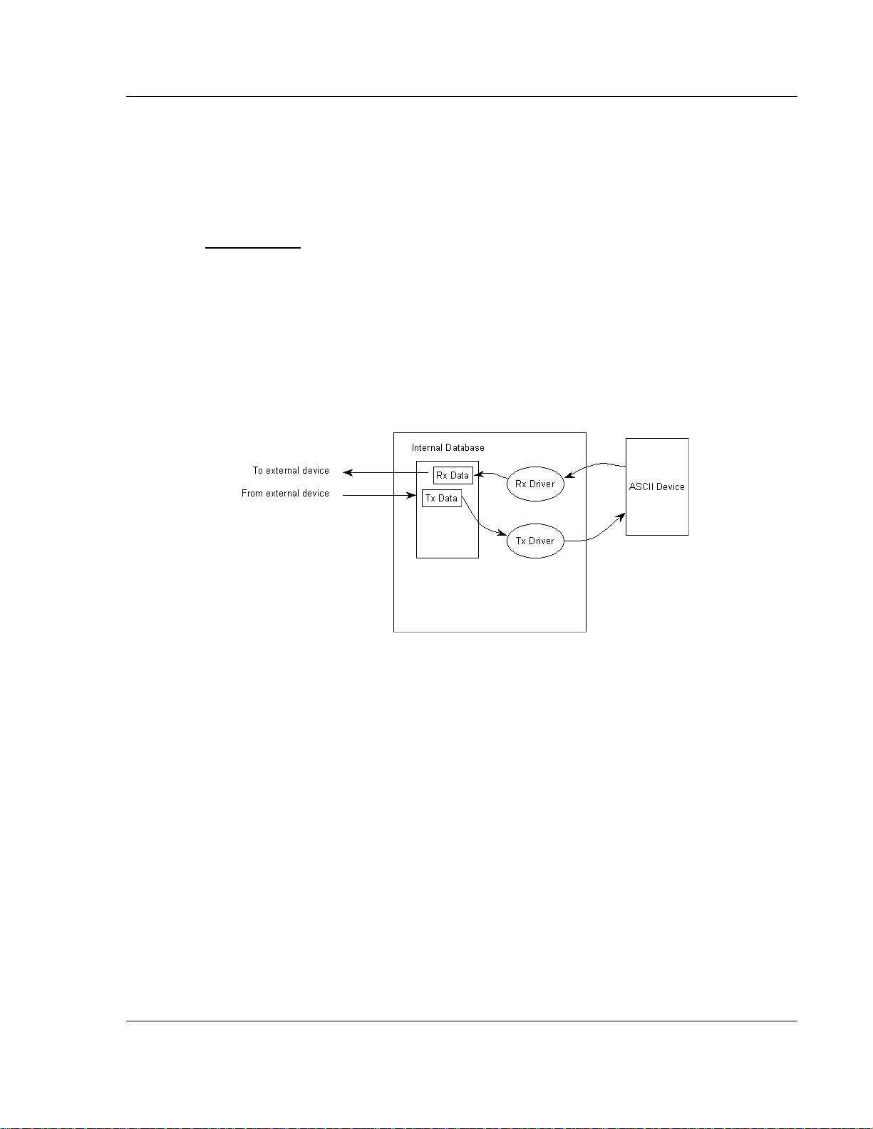
3.1.3 Transmit-Receive Mode
A port configured in transmit-receive mode can send and receive data from an
ASCII device such as a terminal. This mode functions the same way as transmitonly mode or receive-only mode, but handles both the transmit and receive
functions. Data flow to and from an ASCII device is handled by the module's
transmit and receive drivers. Data received from the ASCII device is stored in the
module's internal database until ready to be sent to an external device. Data
received by an external device is also stored in the module's internal database
until ready to be transmitted to the ASCII device. The following illustration shows
the data flow when the port is configured for transmit-receive mode:
Configuring a Port for Transmit-Receive Mode
In order to set a port to both receive data and transmit data to an ASCII device,
ensure that the Rx DB Start parameter and the Tx DB Start parameter both
contain values that specify data storage starting locations. A -1 value in either
parameter will disable the particular function that the parameter serves.
3.2 Termination of Received Data
When data is received on the application port, the user must define in the
configuration when this data will be transferred to the Internal Database within
the module. this is known as the termination type for port. When the termination
condition is met, the data will be sent from the port's receive buffer (data area of
255 bytes) to the Internal Database. This termination type is set in the bit
mapped Type field of the module object. The following illustration shows the bit
map used for this parameter.
ProSoft Technology, Inc. Page 15 of 40
July 7, 2008
Page 16

ASCII ♦ ProLinx Standalone Modes of Operation
Generic ASCII Serial Communication Module
Termination Type Field
Bit(s) 4 to 7 3 2 1 0
Bit Value
Definition
- 8 4 2 1
Reserved
Packet size
limit used
Intercharacter
delay timeout
used
Message
timeout used
Termination
character(s)
used
If none of the bits are set (Type=0), the port will be configured for stream mode.
Any characters received on the port are immediately sent to the processor. The
processor must buffer and assemble a packet of information if this mode is
selected as required by the application. If the data can be handled by the
processor in this mode and it is appropriate for your application, this is the fastest
method of communication between the device and the processor.
Any combination of bits is acceptable to the module and should be set to match
the device on the specific port. An example of each termination type is given
below.
Page 16 of 40 ProSoft Technology, Inc.
July 7, 2008
Page 17

Modes of Operation ASCII ♦ ProLinx Standalone
Generic ASCII Serial Communication Module
ProSoft Technology, Inc. Page 17 of 40
July 7, 2008
Page 18

ASCII ♦ ProLinx Standalone Modes of Operation
Generic ASCII Serial Communication Module
Page 18 of 40 ProSoft Technology, Inc.
July 7, 2008
Page 19

ASCII Protocol Configuration ASCII ♦ ProLinx Standalone
Generic ASCII Serial Communication Module
4 ASCII Protocol Configuration
In This Chapter
[ASCII Port 0] ........................................................................................19
In order for the ASCII driver to function, a minimum amount of configuration data
must be transferred to the module from the module's file system. Care must be
taken in constructing the module configuration parameters. If the module does
not function as expected, examine the configuration file using the Debugger Port
on the module. All configuration parameters for the driver are found under the
[ASCII Port x] section. The x in the section name will have a value of 0 to 3
corresponding to the appropriate ASCII port.
After setting up the configuration file, download it to the module using ProSoft
Configuration Builder.
4.1 [ASCII Port 0]
[ASCII PORT 0]
Enabled : Y #
RS Interface : 0 #0=RS-232, 1=RS-485, 2=RS-422
Rx DB Start : 200
Tx DB Start : 0
Baud Rate : 19200
Parity : N #The coded values are as follows: N=None, O=Odd,
# E=Even, M=Mark and S=Space."
Data Bits : 8 #Valid entries for this field are 5, 6, 7 and 8."
Stop Bits : 1
RTS On : 0
RTS Off : 0
Handshaking : N #Handshake code of N, Y, D, X"
Rx Termination Type: 1
Rx Term Count : 1
Rx Term Chars : 13 11 12 14 15 16 17 255 255 0 0 0
Rx Packet Length : 10
Rx Timeout : 5000
Rx Delay : 1000
Swap Rx Data Bytes : N
Tx Timeout : 5000
Tx Minimum Delay : 0
Swap Tx Data Bytes : N
4.1.1 Enabled
Yes or No
This flag specifies if the port on the module will be utilized. If the parameter is set
to No, the port will not be used. If the parameter is set to Yes, the port will be
used supporting the ASCII protocol.
ProSoft Technology, Inc. Page 19 of 40
July 7, 2008
Page 20

ASCII ♦ ProLinx Standalone ASCII Protocol Configuration
Generic ASCII Serial Communication Module
4.1.2 RS Interface
Code 0 to 2
This parameter specifies the RS interface to be utilized when serial ports are
used on the serial expansion module (Ports 1 to 3). The codes are as follows:
0=RS-232
1=RS-485
2=RS-422
4.1.3 Rx DB Start
-1 or 0 to 3896
This parameter specifies the starting location in the internal database where the
received data will be stored. The buffer holds 130 words, however, the first three
words of the data area define the sequence number, last write byte count and
the Rx message length. If the parameter is set to -1, the port will not receive
data. Refer to Receive Data (page 10) for detailed information on Rx data
structure.
4.1.4 Tx DB Start
-1 or 0 to 3896
This parameter specifies the starting location in the internal database where the
transmit data will be stored. The buffer holds 130 words, however, the first three
words of the data area define the sequence number, last write byte count and
the Rx message length. If the parameter is set to -1, the port will not transmit
data. Refer to Transmit Data (page 10) for detailed information on Tx data
structure.
4.1.5 Baud Rate
Baud Rate Value
This is the baud rate to be used on the port. Enter the baud rate as a value. For
example, to select 19K baud, enter 19200. Valid entries for this field include: 110,
150, 300, 600, 1200, 2400, 4800, 9600, 19200, 28800, 38400, 57600 and 115.
4.1.6 Parity
None, Odd, Even
This is the Parity code to be used for the port. The coded values are as follows:
None, Odd, Even.
Page 20 of 40 ProSoft Technology, Inc.
July 7, 2008
Page 21

ASCII Protocol Configuration ASCII ♦ ProLinx Standalone
Generic ASCII Serial Communication Module
4.1.7 Data Bits
5 to 8
This parameter sets the number of data bits for each word used by the protocol.
Valid entries for this field are 5, 6, 7 and 8.
4.1.8 Stop Bits
1 or 2
This parameter sets the number of stop bits to be used with each data value
sent. Valid entries for this field are 1 and 2.
4.1.9 RTS On
0 to 65535
This parameter sets the RTS presend delay. The value entered represents the
number of milliseconds the module will wait after setting the RTS modem line
before sending the data.
4.1.10 RTS Off
0 to 65535
This parameter specifies the number of milliseconds to delay after sending the
data frame before the RTS line is dropped.
4.1.11 Handshaking
Handshake code of N, Y, D, X
This parameter specifies the handshaking used on the port. The code values are
as follows: N=No hardware or software handshaking, Y=RTS/CTS hardware
handshaking, D=DTR/DSR hardware handshaking and X=XON/XOFF software
handshaking.
4.1.12 Rx Termination Type
Bit coded value of 0 to 15
This parameter specifies the receive termination characteristics for the port. This
value is bit mapped as follows: Bit 0 = Termination character(s) used,
Bit1=Message timeout used, Bit2=Intercharacter delay timeout used and
Bit3=Packet size limit used. If the parameter is set to zero, the port is placed in
stream mode.
4.1.13 Rx Term Count
0 to 12
ProSoft Technology, Inc. Page 21 of 40
July 7, 2008
Page 22

ASCII ♦ ProLinx Standalone ASCII Protocol Configuration
Generic ASCII Serial Communication Module
This parameter is used if bit 0 of the Type parameter is set. This value (0 to 12)
defines the number of termination characters used to define the end of received
message.
4.1.14 Rx Term Chars
ASCII Characters
This array of 12 characters defines the termination characters at the end of each
received message. Each character occupies one position in the array. The
number of characters to be used in the array is set in the RTermCnt parameter.
4.1.15 Rx Packet Length
0 to 200
This parameter is used if bit 3 is set in the Type parameter. The parameter sets
the length of data required to be received on the port before transferring the data
to the processor.
4.1.16 Rx Timeout
0 to 65535
This parameter is used if bit 1 is set in the Type parameter. The parameter sets
the number of milliseconds to wait after the first character is received on the port
before automatically sending the data to the processor.
4.1.17 Rx Delay
0 to 65535
This parameter is used if bit 2 is set in the Type parameter. The parameter sets
the number of milliseconds to wait between each character received on the port
before sending the data to the processor.
4.1.18 Swap Rx Data Bytes
Yes or No
This parameter is determines if the data received by the module will have the
byte order of the data swapped. If the parameter is set to No, no byte swapping
will occur. If the parameter is set to Yes, the odd byte will be swapped with the
even byte in each word of data received.
4.1.19 Tx Timeout
0 to 65535
This parameter specifies the timeout period to transmit a message out the port. A
message must be transmitted out the port within the specified timeout period.
Message transmission will be aborted if the timeout is exceeded.
Page 22 of 40 ProSoft Technology, Inc.
July 7, 2008
Page 23

ASCII Protocol Configuration ASCII ♦ ProLinx Standalone
Generic ASCII Serial Communication Module
4.1.20 Tx Minimum Delay
0 to 65535
This parameter specifies the minimum number of milliseconds to delay before
transmitting a message out the port. This pre-send delay is applied before the
RTS on time. This may be required when communicating with slow devices.
4.1.21 Swap Tx Data Bytes
Yes or No
This parameter determines if the data to be transmitted by the module will have
the byte order of the data swapped. If the parameter is set to No, no byte
swapping will occur. If the parameter is set to Yes, the odd byte will be swapped
with the even byte in each word of data received.
ProSoft Technology, Inc. Page 23 of 40
July 7, 2008
Page 24

ASCII ♦ ProLinx Standalone ASCII Protocol Configuration
Generic ASCII Serial Communication Module
Page 24 of 40 ProSoft Technology, Inc.
July 7, 2008
Page 25

Driver Status Data ASCII ♦ ProLinx Standalone Generic ASCII Serial Communication Module
5 Driver Status Data
Each ASCII port associated with the ASCII driver has an associated status data
area. This data is located in the virtual address range of the module. The map
data functionality of the module must be used to map this data into the normal
data range of the module's database. The following table lists the content of the
status data areas associated with each ASCII port driver:
Port 0 Status Data
Status Register Description
13000 Receive State:
-1 = Listening for data
1 = Receiving Port Data
2 = Waiting for Backplane transfer
13001 Receive character count
13002 Receive message count
13003 Transmit State:
0 = Waiting for Data to Send
1 = RTS On
2 = RTS Timeout
3 = Sending data
4 = Waiting for RTS Off
5 = RTS turned off
30 = Intercharacter Delay
31 = Intercharacter Delay
32 = Intercharacter Delay
100 = Message Delay before Transmit
101 = Message Delay before Transmit
13004 Transmit character count
13005 Transmit message count
13006 Configuration error word
13007 to 13009 No Valid Data
Port 1 Status Data
Status Register Description
13010 Receive State:
-1 = Listening for data
1 = Receiving Port Data
2 = Waiting for Backplane transfer
13011 Receive character count
13012 Receive message count
ProSoft Technology, Inc. Page 25 of 40
July 7, 2008
Page 26

ASCII ♦ ProLinx Standalone Driver Status Data
Generic ASCII Serial Communication Module
Status Register Description
13013 Transmit State:
0 = Waiting for Data to Send
1 = RTS On
2 = RTS Timeout
3 = Sending data
4 = Waiting for RTS Off
5 = RTS turned off
30 = Intercharacter Delay
31 = Intercharacter Delay
32 = Intercharacter Delay
100 = Message Delay before Transmit
101 = Message Delay before Transmit
13014 Transmit character count
13015 Transmit message count
13016 Configuration error word
13017 to 13019 No Valid Data
Port 2 Status Data
Status Register Description
13020 Receive State:
-1 = Listening for data
1 = Receiving Port Data
2 = Waiting for Backplane transfer
13021 Receive character count
13022 Receive message count
13023 Transmit State:
0 = Waiting for Data to Send
1 = RTS On
2 = RTS Timeout
3 = Sending data
4 = Waiting for RTS Off
5 = RTS turned off
30 = Intercharacter Delay
31 = Intercharacter Delay
32 = Intercharacter Delay
100 = Message Delay before Transmit
101 = Message Delay before Transmit
13024 Transmit character count
13025 Transmit message count
13026 Configuration error word
13027 to 13029 No Valid Data
Page 26 of 40 ProSoft Technology, Inc.
July 7, 2008
Page 27

Driver Status Data ASCII ♦ ProLinx Standalone
Generic ASCII Serial Communication Module
Port 3 Status Data
Status Register Description
13030 Receive State:
-1 = Listening for data
1 = Receiving Port Data
2 = Waiting for Backplane transfer
13031 Receive character count
13032 Receive message count
13033 Transmit State:
0 = Waiting for Data to Send
1 = RTS On
2 = RTS Timeout
3 = Sending data
4 = Waiting for RTS Off
5 = RTS turned off
30 = Intercharacter Delay
31 = Intercharacter Delay
32 = Intercharacter Delay
100 = Message Delay before Transmit
101 = Message Delay before Transmit
13034 Transmit character count
13035 Transmit message count
13036 Configuration error word
13037 to 13039 No Valid Data
If the module is configured correctly, the configuration error word should have a
value of zero. Any other value indicates a configuration error. Use the value in
the configuration error word to determine which set of parameters are invalid in
the driver configuration area. The following table lists the bits associated with
each configuration error in the word:
Bit Code Description
0 0x0001 Invalid selection for enabled parameter
1 0x0002 Invalid Rx DB Start parameter
2 0x0004 Invalid Tx DB Start parameter
3 0x0008 Invalid Baud Rate
4 0x0010 Invalid Parity (N, O, E, M or S)
5 0x0020 Invalid Data bits (5 to 8)
6 0x0040 Invalid Stop bits (1 or 2)
7 0x0080 Invalid Handshaking parameter (N, Y, D or X)
8 0x0100 Invalid Rx Termination Type
9 0x0200 Invalid Rx Term Count value
10 0x0400 Invalid Rx Timeout
11 0x0800 Invalid Rx Delay
12 0x1000 Invalid Rx Packet Length
ProSoft Technology, Inc. Page 27 of 40
July 7, 2008
Page 28

ASCII ♦ ProLinx Standalone Driver Status Data
Generic ASCII Serial Communication Module
Bit Code Description
13 0x2000 Invalid Tx Timeout
14 0x4000 Invalid RS interface selected (0 to 2)
15 0x8000
Page 28 of 40 ProSoft Technology, Inc.
July 7, 2008
Page 29

LED Indicators ASCII ♦ ProLinx Standalone Generic ASCII Serial Communication Module
6 LED Indicators
In This Chapter
Base Module LEDs................................................................................29
LEDs for Port 0 Serial Port ....................................................................30
4101 Series LEDs .................................................................................30
Troubleshooting the operation of the DNP Slave port can be performed using
several methods.
The first and quickest is to scan the LEDs on the module to determine the
existence and possibly the cause of a problem. This section provides insight into
the operation of the Serial Port status LEDs. Information on the module's other
LEDs can be found in the ProLinx Reference Guide.
6.1 Base Module LEDs
LED State Description
Power
Err
Off
Green Solid
Off Normal operation. Fault
Red Solid
Off Normal operation. Cfg
Amber Solid
Off Normal operation.
Flashing
Solid Red
Power is not connected to the power terminals. This LED is hardware
driven, so it only requires power to operate.
Power is connected to the power terminals. Verify that the other LEDs
for operational and functional status.
A critical error has occurred. Program executable has failed or has
been user-terminated and is no longer running. Press Reset p/b or
cycle power to clear error. If not, use the Debug procedures described
later in this manual.
The unit is in the configuration mode. The configuration file is being
read and the unit is implementing the configuration values and
initializing the hardware. This will occur during power cycle, or after
pressing the reset button. It also occurs after a cold/warm boot
command is received.
An error condition has been detected and is occurring. Check
configuration.
This condition is indicative of a large number of errors in the
application interface communications. The module's error flag is
cleared at the start of each command (master/client) or receipt of data
(slave/adapter/server).
ProSoft Technology, Inc. Page 29 of 40
July 7, 2008
Page 30

ASCII ♦ ProLinx Standalone LED Indicators
Generic ASCII Serial Communication Module
6.2 LEDs for Port 0 Serial Port
Some ProLinx modules have three extra serial ports. Each of these serial ports
has two LEDs indicating status.
LED Color Description
Off No activity on the port. Port 0 - ACT
The port is either actively transmitting or receiving
data
Normal state. When off and Port Active led is
indicating activity, there are no communication errors
Activity on this led indicates some communication
error was detected, either during transmit or receive
Port 0 - ERR
Green Flash
Off
Red On or Flashing
6.3 4101 Series LEDs
LED State Description
Power
ERR
Off
Green Solid
Off Normal operation. Fault
Red Solid
Off Normal operation. CFG
Amber Solid
Off Normal operation.
Flashing
Solid Red
Power is not connected to the power terminals. This LED is hardware
driven, so it only requires power to operate.
Power is connected to the power terminals. Verify that the other LEDs
for operational and functional status.
The Debug/Configuration mode is active (applies to modules that
support pass-through on Debug port - such as DFCM units).
If CFG LED is not on, a critical error has occurred. Program
executable has failed or has been user-terminated and is no longer
running. Press Reset p/b or cycle power to clear error. If not, use the
Debug procedures described later in this manual.
If Fault LED is on, the Debug/Configuration Mode is active (if the
module supports pass-through on the Debug port - such as DFCM
units).
If the Fault LED is off, the unit is in the configuration mode. The
configuration file is being read and the unit is implementing the
configuration values and initializing the hardware. This will occur
during power cycle, or after pressing reset button. It also occurs after
a cold/warm boot command is received.
An error condition has been detected and is occurring. Check
configuration.
This condition is indicative of a large number of errors in the
application interface communications. The module's error flag is
cleared at the start of each command (master/client) or receipt of data
(slave/adapter/server).
Page 30 of 40 ProSoft Technology, Inc.
July 7, 2008
Page 31

Support, Service & Warranty ASCII ♦ ProLinx Standalone
Generic ASCII Serial Communication Module
7 Support, Service & W arranty
In This Chapter
Return Material Authorization (RMA) Policies and Conditions............... 31
LIMITED WARRANTY........................................................................... 33
How to Contact Us: Technical Support.................................................. 37
ProSoft Technology, Inc. (ProSoft) is committed to providing the most efficient
and effective support possible. Before calling, please gather the following
information to assist in expediting this process:
1 Product Version Number
2 System architecture
3 Network details
If the issue is hardware related, we will also need information regarding:
1 Module configuration and contents of file
o Module Operation
o Configuration/Debug status information
o LED patterns
2 Information about the processor and user data files as viewed through and
LED patterns on the processor.
3 Details about the serial devices interfaced, if any.
7.1 Return Material Authorization (RMA) Policies and Conditions
The following RMA Policies and Conditions (collectively, "RMA Policies") apply to
any returned Product. These RMA Policies are subject to change by ProSoft
without notice. For warranty information, see "Limited Warranty". In the event of
any inconsistency between the RMA Policies and the Warranty, the Warranty
shall govern.
7.1.1 Procedures for Return of Units Under Warranty:
A Technical Support Engineer must approve the return of Product under
ProSoft's Warranty:
a) A replacement module will be shipped and invoiced. A purchase order will
be required.
b) Credit for a product under warranty will be issued upon receipt of
authorized product by ProSoft at designated location referenced on the
Return Material Authorization.
ProSoft Technology, Inc. Page 31 of 40
July 7, 2008
Page 32

ASCII ♦ ProLinx Standalone Support, Service & Warranty
Generic ASCII Serial Communication Module
• If a defect is found and is determined to be customer generated, or if the
defect is otherwise not covered by ProSoft's Warranty, there will be no credit
given. Customer will be contacted and can request module be returned at
their expense.
7.1.2 Procedures for Return of Units Out of Warranty:
a) Customer sends unit in for evaluation
b) If no defect is found, Customer will be charged the equivalent of $100
USD, plus freight charges, duties and taxes as applicable. A new
purchase order will be required.
c) If unit is repaired, charge to Customer will be 30% of current list price
(USD) plus freight charges, duties and taxes as applicable. A new
purchase order will be required or authorization to use the purchase order
submitted for evaluation fee.
The following is a list of non-repairable units:
o 3150 - All
o 3750
o 3600 - All
o 3700
o 3170 - All
o 3250
o 1560 - Can be repaired, only if defect is the power supply
o 1550 - Can be repaired, only if defect is the power supply
o 3350
o 3300
o 1500 - All
7.1.3 All Product Returns:
a) In order to return a Product for repair, exchange or otherwise, the
Customer must obtain a Returned Material Authorization (RMA) number
from ProSoft and comply with ProSoft shipping instructions.
b) In the event that the Customer experiences a problem with the Product for
any reason, Customer should contact ProSoft Technical Support at one of
the telephone numbers listed above (page 37). A Technical Support
Engineer will request that you perform several tests in an attempt to
isolate the problem. If after completing these tests, the Product is found to
be the source of the problem, we will issue an RMA.
c) All returned Products must be shipped freight prepaid, in the original
shipping container or equivalent, to the location specified by ProSoft, and
be accompanied by proof of purchase and receipt date. The RMA number
is to be prominently marked on the outside of the shipping box. Customer
agrees to insure the Product or assume the risk of loss or damage in
transit. Products shipped to ProSoft using a shipment method other than
that specified by ProSoft or shipped without an RMA number will be
returned to the Customer, freight collect. Contact ProSoft Technical
Support for further information.
Page 32 of 40 ProSoft Technology, Inc.
July 7, 2008
Page 33

Support, Service & Warranty ASCII ♦ ProLinx Standalone
Generic ASCII Serial Communication Module
d) A 10% restocking fee applies to all warranty credit returns whereby a
Customer has an application change, ordered too many, does not need,
etc.
7.1.4 Purchasing Warranty Extension:
a) ProSoft's standard warranty period is three (3) years from the date of
shipment as detailed in "Limited Warranty (page 33)". The Warranty
Period may be extended at the time of equipment purchase for an
additional charge, as follows:
• Additional 1 year = 10% of list price
• Additional 2 years = 20% of list price
• Additional 3 years = 30% of list price
7.2 LIMITED WARRANTY
This Limited Warranty ("Warranty") governs all sales of hardware, software and
other products (collectively, "Product") manufactured and/or offered for sale by
ProSoft, and all related services provided by ProSoft, including maintenance,
repair, warranty exchange, and service programs (collectively, "Services"). By
purchasing or using the Product or Services, the individual or entity purchasing or
using the Product or Services ("Customer") agrees to all of the terms and
provisions (collectively, the "Terms") of this Limited Warranty. All sales of
software or other intellectual property are, in addition, subject to any license
agreement accompanying such software or other intellectual property.
7.2.1 What Is Covered By This Warranty
a) Warranty On New Products: ProSoft warrants, to the original purchaser,
that the Product that is the subject of the sale will (1) conform to and
perform in accordance with published specifications prepared, approved
and issued by ProSoft, and (2) will be free from defects in material or
workmanship; provided these warranties only cover Product that is sold as
new. This Warranty expires three years from the date of shipment (the
"Warranty Period"). If the Customer discovers within the Warranty Period
a failure of the Product to conform to specifications, or a defect in material
or workmanship of the Product, the Customer must promptly notify
ProSoft by fax, email or telephone. In no event may that notification be
received by ProSoft later than 39 months. Within a reasonable time after
notification, ProSoft will correct any failure of the Product to conform to
specifications or any defect in material or workmanship of the Product,
with either new or used replacement parts. Such repair, including both
parts and labor, will be performed at ProSoft's expense. All warranty
service will be performed at service centers designated by ProSoft.
ProSoft Technology, Inc. Page 33 of 40
July 7, 2008
Page 34

ASCII ♦ ProLinx Standalone Support, Service & Warranty
Generic ASCII Serial Communication Module
b) Warranty On Services: Materials and labor performed by ProSoft to repair
a verified malfunction or defect are warranteed in the terms specified
above for new Product, provided said warranty will be for the period
remaining on the original new equipment warranty or, if the original
warranty is no longer in effect, for a period of 90 days from the date of
repair.
7.2.2 What Is Not Covered By This Warranty
a) ProSoft makes no representation or warranty, expressed or implied, that
the operation of software purchased from ProSoft will be uninterrupted or
error free or that the functions contained in the software will meet or
satisfy the purchaser's intended use or requirements; the Customer
assumes complete responsibility for decisions made or actions taken
based on information obtained using ProSoft software.
b) This Warranty does not cover the failure of the Product to perform
specified functions, or any other non-conformance, defects, losses or
damages caused by or attributable to any of the following: (i) shipping; (ii)
improper installation or other failure of Customer to adhere to ProSoft's
specifications or instructions; (iii) unauthorized repair or maintenance; (iv)
attachments, equipment, options, parts, software, or user-created
programming (including, but not limited to, programs developed with any
IEC 61131-3, "C" or any variant of "C" programming languages) not
furnished by ProSoft; (v) use of the Product for purposes other than those
for which it was designed; (vi) any other abuse, misapplication, neglect or
misuse by the Customer; (vii) accident, improper testing or causes
external to the Product such as, but not limited to, exposure to extremes
of temperature or humidity, power failure or power surges; or (viii)
disasters such as fire, flood, earthquake, wind and lightning.
c) The information in this Agreement is subject to change without notice.
ProSoft shall not be liable for technical or editorial errors or omissions
made herein; nor for incidental or consequential damages resulting from
the furnishing, performance or use of this material. The user guide
included with your original product purchase from ProSoft contains
information protected by copyright. No part of the guide may be duplicated
or reproduced in any form without prior written consent from ProSoft.
7.2.3 Disclaimer Regarding High Risk Activities
Product manufactured or supplied by ProSoft is not fault tolerant and is not
designed, manufactured or intended for use in hazardous environments requiring
fail-safe performance including and without limitation: the operation of nuclear
facilities, aircraft navigation of communication systems, air traffic control, direct
life support machines or weapons systems in which the failure of the product
could lead directly or indirectly to death, personal injury or severe physical or
environmental damage (collectively, "high risk activities"). ProSoft specifically
disclaims any express or implied warranty of fitness for high risk activities.
Page 34 of 40 ProSoft Technology, Inc.
July 7, 2008
Page 35

Support, Service & Warranty ASCII ♦ ProLinx Standalone
Generic ASCII Serial Communication Module
7.2.4 Limitation of Remedies **
In no event will ProSoft or its Dealer be liable for any special, incidental or
consequential damages based on breach of warranty, breach of contract,
negligence, strict tort or any other legal theory. Damages that ProSoft or its
Dealer will not be responsible for included, but are not limited to: Loss of profits;
loss of savings or revenue; loss of use of the product or any associated
equipment; loss of data; cost of capital; cost of any substitute equipment,
facilities, or services; downtime; the claims of third parties including, customers of
the Purchaser; and, injury to property.
** Some areas do not allow time limitations on an implied warranty, or allow the exclusion or
limitation of incidental or consequential damages. In such areas, the above limitations may not
apply. This Warranty gives you specific legal rights, and you may also have other rights which vary
from place to place.
7.2.5 Time Limit for Bringing Suit
Any action for breach of warranty must be commenced within 39 months
following shipment of the Product.
7.2.6 Intellectual Property Indemnity
Buyer shall indemnify and hold harmless ProSoft and its employees from and
against all liabilities, losses, claims, costs and expenses (including attorney's
fees and expenses) related to any claim, investigation, litigation or proceeding
(whether or not ProSoft is a party) which arises or is alleged to arise from Buyer's
acts or omissions under these Terms or in any way with respect to the Products.
Without limiting the foregoing, Buyer (at its own expense) shall indemnify and
hold harmless ProSoft and defend or settle any action brought against such
Companies to the extent based on a claim that any Product made to Buyer
specifications infringed intellectual property rights of another party. ProSoft
makes no warranty that the product is or will be delivered free of any person's
claiming of patent, trademark, or similar infringement. The Buyer assumes all
risks (including the risk of suit) that the product or any use of the product will
infringe existing or subsequently issued patents, trademarks, or copyrights.
a) Any documentation included with Product purchased from ProSoft is
protected by copyright and may not be duplicated or reproduced in any
form without prior written consent from ProSoft.
b) ProSoft's technical specifications and documentation that are included
with the Product are subject to editing and modification without notice.
c) Transfer of title shall not operate to convey to Customer any right to make,
or have made, any Product supplied by ProSoft.
d) Customer is granted no right or license to use any software or other
intellectual property in any manner or for any purpose not expressly
permitted by any license agreement accompanying such software or other
intellectual property.
ProSoft Technology, Inc. Page 35 of 40
July 7, 2008
Page 36

ASCII ♦ ProLinx Standalone Support, Service & Warranty
Generic ASCII Serial Communication Module
e) Customer agrees that it shall not, and shall not authorize others to, copy
software provided by ProSoft (except as expressly permitted in any
license agreement accompanying such software); transfer software to a
third party separately from the Product; modify, alter, translate, decode,
decompile, disassemble, reverse-engineer or otherwise attempt to derive
the source code of the software or create derivative works based on the
software; export the software or underlying technology in contravention of
applicable US and international export laws and regulations; or use the
software other than as authorized in connection with use of Product.
f) Additional Restrictions Relating To Software And Other Intellectual
Property
In addition to compliance with the Terms of this Warranty, Customers
purchasing software or other intellectual property shall comply with any
license agreement accompanying such software or other intellectual
property. Failure to do so may void this Warranty with respect to such
software and/or other intellectual property.
7.2.7 Disclaimer of all Other Warranties
The Warranty set forth in What Is Covered By This Warranty (page 33) are in lieu
of all other warranties, express or implied, including but not limited to the implied
warranties of merchantability and fitness for a particular purpose.
7.2.8 No Other Warranties
Unless modified in writing and signed by both parties, this Warranty is
understood to be the complete and exclusive agreement between the parties,
suspending all oral or written prior agreements and all other communications
between the parties relating to the subject matter of this Warranty, including
statements made by salesperson. No employee of ProSoft or any other party is
authorized to make any warranty in addition to those made in this Warranty. The
Customer is warned, therefore, to check this Warranty carefully to see that it
correctly reflects those terms that are important to the Customer.
7.2.9 Allocation of Risks
This Warranty allocates the risk of product failure between ProSoft and the
Customer. This allocation is recognized by both parties and is reflected in the
price of the goods. The Customer acknowledges that it has read this Warranty,
understands it, and is bound by its Terms.
Page 36 of 40 ProSoft Technology, Inc.
July 7, 2008
Page 37

Support, Service & Warranty ASCII ♦ ProLinx Standalone
Generic ASCII Serial Communication Module
7.2.10 Controlling Law and Severability
This Warranty shall be governed by and construed in accordance with the laws of
the United States and the domestic laws of the State of California, without
reference to its conflicts of law provisions. If for any reason a court of competent
jurisdiction finds any provisions of this Warranty, or a portion thereof, to be
unenforceable, that provision shall be enforced to the maximum extent
permissible and the remainder of this Warranty shall remain in full force and
effect. Any cause of action with respect to the Product or Services must be
instituted in a court of competent jurisdiction in the State of California.
7.3 How to Contact Us: Technical Support
Internet Web Site: http://www.prosoft-technology.com/support
(http://www.prosoft-technology.com/support)
E-mail address: support@prosoft-technology.com
(mailto:support@prosoft-technology.com)
Asia Pacific
+603.7724.2080, support.asia@prosoft-technology.com
(mailto:support.asia@prosoft-technology.com)
Languages spoken include: Chinese, English
Europe (location in Toulouse, France)
+33 (0) 5.34.36.87.20, support.EMEA@prosoft-technology.com
(mailto:support.emea@prosoft-technology.com)
Languages spoken include: French, English
North America/Latin America (excluding Brasil) (location in California)
+1.661.716.5100, support@prosoft-technology.com (mailto:support@prosofttechnology.com)
Languages spoken include: English, Spanish
For technical support calls within the United States, an after-hours answering
system allows pager access to one of our qualified technical and/or application
support engineers at any time to answer your questions.
Brasil (location in Sao Paulo)
+55-11-5084-5178 , eduardo@prosoft-technology.com (mailto:eduardo@prosofttechnology.com)
Languages spoken include: Portuguese, English
ProSoft Technology, Inc. Page 37 of 40
July 7, 2008
Page 38

ASCII ♦ ProLinx Standalone Support, Service & Warranty
Generic ASCII Serial Communication Module
Page 38 of 40 ProSoft Technology, Inc.
July 7, 2008
Page 39

Index ASCII ♦ ProLinx Standalone
Generic ASCII Serial Communication Module
L
LED Indicators • 29
Index
LEDs for Port 0 Serial Port • 30
Limitation of Remedies ** • 35
LIMITED WARRANTY • 33
[
[ASCII Port 0] • 19
4
4101 Series LEDs • 30
A
All Product Returns: • 32
All ProLinx® Products • 2
Allocation of Risks • 36
ASCII Protocol Configuration • 19
B
Base Module LEDs • 29
Baud Rate • 20
C
Configuring a Port for Transmit-Only Mode • 14
Configuring a Port for Transmit-Receive Mode • 15
Configuring the Port for Receive-Only Mode • 14
Controlling Law and Severability • 37
D
Data Bits • 21
Data Flow • 9, 13
Disclaimer of all Other Warranties • 36
Disclaimer Regarding High Risk Activities • 34
Driver Status Data • 25
E
Enabled • 19
M
Modes of Operation • 13
N
No Other Warranties • 36
P
Parity • 20
Please Read This Notice • 2
Procedures for Return of Units Out of Warranty: • 32
Procedures for Return of Units Under Warranty: • 31
Product Installation Warning • 4
ProLinx Modules with Ethernet Ports • 3
ProLinx Plus with Radio • 3
ProLinx Series C (4000); ProLinx Plus (5000) • 4
Purchasing Warranty Extension: • 33
R
Receive Data • 10, 20
Receive-Only Mode • 13
Resources • 7
Return Material Authorization (RMA) Policies and
Conditions • 31
RS Interface • 20
RTS Off • 21
RTS On • 21
Rx DB Start • 20
Rx Delay • 22
Rx Packet Length • 22
Rx Term Chars • 22
Rx Term Count • 21
Rx Termination Type • 21
Rx Timeout • 22
F
Functionality • 9
G
General Specifications • 7
H
Handshaking • 21
How to Contact Us
Technical Support • 32, 37
I
Important Installation Instructions • 2
Intellectual Property Indemnity • 35
Introduction • 7
Stop Bits • 21
Support, Service & Warranty • 31
Swap Rx Data Bytes • 22
Swap Tx Data Bytes • 23
Termination of Received Data • 15
Time Limit for Bringing Suit • 35
To Order a Series C mode with the -WEB option: • 3
To upgrade a previously purchased Series C model: •
3
Transmit Data • 10, 20
Transmit-Only Mode • 14
Transmit-Receive Mode • 15
Tx DB Start • 20
Tx Minimum Delay • 23
Tx Timeout • 22
S
T
ProSoft Technology, Inc. Page 39 of 40
July 7, 2008
Page 40

ASCII ♦ ProLinx Standalone Index
Generic ASCII Serial Communication Module
W
What Is Covered By This Warranty • 33, 36
What Is Not Covered By This Warranty • 34
Y
Your Feedback Please • 4
Page 40 of 40 ProSoft Technology, Inc.
July 7, 2008
 Loading...