

Page 1
104C Version 3
ProLinx Gateway
IEC 60870-5-104 Client (Firmware
v3.xx)
August 04, 2011
PROTOCOL MANUAL
Page 2

Your Feedback Please
We always want you to feel that you made the right decision to use our products. If you have suggestions, comments,
compliments or complaints about our products, documentation, or support, please write or call us.
How to Contact Us
ProSoft Technology
5201 Truxtun Ave., 3rd Floor
Bakersfield, CA 93309
+1 (661) 716-5100
+1 (661) 716-5101 (Fax)
www.prosoft-technology.com
support@prosoft-technology.com
Copyright © 2011 ProSoft Technology, Inc., all rights reserved.
104C Version 3 Protocol Manual
August 04, 2011
ProSoft Technology ®, ProLinx ®, inRAx ®, ProTalk ®, and RadioLinx ® are Registered Trademarks of ProSoft
Technology, Inc. All other brand or product names are or may be trademarks of, and are used to identify products
and services of, their respective owners.
ProSoft Technology® Product Documentation
In an effort to conserve paper, ProSoft Technology no longer includes printed manuals with our product shipments.
User Manuals, Datasheets, Sample Ladder Files, and Configuration Files are provided on the enclosed CD-ROM in
Adobe® Acrobat Reader file format (.PDFs). These product documentation files may also be freely downloaded from
our web site: www.prosoft-technology.com
Page 3

Important Installation Instructions
Power, Input, and Output (I/O) wiring must be in accordance with Class I, Division 2 wiring methods, Article 501-4 (b)
of the National Electrical Code, NFPA 70 for installation in the U.S., or as specified in Section 18-1J2 of the Canadian
Electrical Code for installations in Canada, and in accordance with the authority having jurisdiction. The following
warnings must be heeded:
WARNING - EXPLOSION HAZARD - SUBSTITUTION OF COMPONENTS MAY IMPAIR SUITABILITY FOR CLASS
I, DIV. 2;
WARNING - EXPLOSION HAZARD - WHEN IN HAZARDOUS LOCATIONS, TURN OFF POWER BEFORE
REPLACING OR WIRING MODULES
WARNING - EXPLOSION HAZARD - DO NOT DISCONNECT EQUIPMENT UNLESS POWER HAS BEEN
SWITCHED OFF OR THE AREA IS KNOWN TO BE NON-HAZARDOUS.
THIS DEVICE SHALL BE POWERED BY CLASS 2 OUTPUTS ONLY.
ProLinx® Products Warnings
WARNING – EXPLOSION HAZARD – DO NOT DISCONNECT EQUIPMENT UNLESS POWER HAS BEEN
SWITCHED OFF OR THE AREA IS KNOWN TO BE NON-HAZARDOUS.
AVERTISSEMENT – RISQUE D'EXPLOSION – AVANT DE DÉCONNECTER L'EQUIPMENT, COUPER LE
COURANT OU S'ASSURER QUE L'EMPLACEMENT EST DÉSIGNÉ NON DANGEREUX.
ProLinx Gateways with Ethernet Ports
Series C ProLinx™ Gateways with Ethernet ports do NOT include the HTML Web Server. The HTML Web Server
must be ordered as an option. This option requires a factory-installed hardware addition. The HTML Web Server now
supports:
8 MB file storage for HTML files and associated graphics files (previously limited to 384K)
32K maximum HTML page size (previously limited to 16K)
To upgrade a previously purchased Series C model
Contact your ProSoft Technology distributor to order the upgrade and obtain a Returned Merchandise Authorization
(RMA) to return the unit to ProSoft Technology.
To order a ProLinx Plus gateway with the -WEB option
Add -WEB to the standard ProLinx part number. For example, 5201-MNET-MCM-WEB.
Page 4

Markings
Label Markings
<cULus>
E183151
Class I Div 2
Groups A,B,C,D T6
-30°C <= Ta <= 60°C
<Ex>
II 3 G
Ex nA IIC T4
-20°C <= Ta <= 50°C
II – Equipment intended for above ground use (not for use in mines).
3 – Category 3 equipment, investigated for normal operation only.
G – Equipment protected against explosive gasses.
Page 5

104C Version 3 ♦ ProLinx Gateway Contents
IEC 60870-5-104 Client (Firmware v3.xx) Protocol Manual
Contents
Your Feedback Please ........................................................................................................................ 2
How to Contact Us .............................................................................................................................. 2
ProSoft Technology® Product Documentation .................................................................................... 2
Important Installation Instructions ....................................................................................................... 3
ProLinx® Products Warnings ............................................................................................................... 3
ProLinx Gateways with Ethernet Ports ............................................................................................... 3
To upgrade a previously purchased Series C model ..................................................................... 3
To order a ProLinx Plus gateway with the -WEB option ................................................................ 3
Markings .............................................................................................................................................. 4
Guide to the 104C Module Protocol Manual 9
1 Start Here 11
1.1
1.2
1.2.1
ProLinx Reference Guide ........................................................................................ 12
Installing ProSoft Configuration Builder Software ................................................... 13
Using the Online Help ............................................................................................. 13
2 Configuring the Gateway 15
2.1
2.2
2.3
2.4
2.5
2.1.1
2.1.2
2.1.3
2.1.4
2.1.5
2.1.6
2.2.1
2.2.2
2.2.3
2.2.4
2.2.5
IEC 60870-5-104 Client Section .............................................................................. 16
[SNTP CLIENT] ....................................................................................................... 17
[IEC-870-5-104] ....................................................................................................... 19
[IEC-60870-5-104 Client x] ...................................................................................... 21
[IEC-60870-5-104 Client x Sector x] Parameters .................................................... 24
[IEC-60870-5-104 Client x Sector y] ....................................................................... 26
[IEC-60870-5-104 Client Commands] ..................................................................... 28
Using the CommonNet Data Map ........................................................................... 35
From Address .......................................................................................................... 36
To Address .............................................................................................................. 36
Register Count ........................................................................................................ 36
Swap Code .............................................................................................................. 37
Delay Preset ............................................................................................................ 38
Downloading a File from PC to the Module ............................................................. 39
Creating Optional Comment Entries ....................................................................... 40
Printing a Configuration File .................................................................................... 41
3 IEC-60870-5-104 Protocol Implementation 43
3.1
3.1.1
3.2
3.3
3.3.1
3.4
3.4.1
3.4.2
Module Address ...................................................................................................... 44
IP Address ............................................................................................................... 44
Monitor Direction and Control Direction: Information Object Definition .................. 46
Using Monitor Points ............................................................................................... 49
Monitor Information Objects Addressing ................................................................. 49
Using Control (Command) Information Objects ...................................................... 57
Control Information Objects Addressing ................................................................. 58
TESTFR Requests .................................................................................................. 64
ProSoft Technology, Inc. Page 5 of 139
August 4, 2011
Page 6

Contents 104C Version 3 ♦ ProLinx Gateway
Protocol Manual IEC 60870-5-104 Client (Firmware v3.xx)
4 Mailbox Feature (x201-DFNT-104C) 67
4.1
4.2
4.3
4.4
4.5
4.6
4.7
4.8
4.9
4.10
User Constructed Command Mailbox (9901) ......................................................... 70
Command Control Block Mailbox (9902) ................................................................ 72
Event Messages from Outstations Mailbox (9903) ................................................. 73
General Gateway Status Mailbox (9250) ................................................................ 76
Client X Status Data Mailbox (9251) ...................................................................... 78
Command List Error Data Mailbox (9950) .............................................................. 81
Get Gateway Time Mailbox (9970) ......................................................................... 83
Set Gateway Time Mailbox (9971) ......................................................................... 85
Reset Status Data Mailbox (9997) .......................................................................... 87
Coldboot Mailbox (9998/9999) ................................................................................ 88
5 Diagnostics and Troubleshooting 91
5.1
5.2
5.2.1
5.2.2
5.2.3
5.2.4
5.2.5
5.2.6
5.2.7
Ethernet LED Indicators .......................................................................................... 92
Using ProSoft Configuration Builder (PCB) for Diagnostics ................................... 93
Required Hardware ................................................................................................. 93
Using the Diagnostic Window in ProSoft Configuration Builder ............................. 93
Navigation ............................................................................................................... 96
Main Menu .............................................................................................................. 97
Database View Menu .............................................................................................. 99
IEC-870-5-104 Client Menu .................................................................................. 101
Network Menu ....................................................................................................... 104
6 Reference 105
6.1
6.2
6.3
6.4
6.1.1
6.1.2
6.1.3
6.1.4
6.2.1
6.4.1
6.4.2
6.4.3
6.4.4
6.4.5
Product Specifications .......................................................................................... 106
General Specifications .......................................................................................... 106
Internal Database ................................................................................................. 106
Hardware Specifications ....................................................................................... 108
Port Physical and Protocol Specifications ............................................................ 109
SNTP Support ....................................................................................................... 110
SNTP Status Data ................................................................................................ 110
Server Error and Status Data ............................................................................... 111
IEC 60870-5-104 Client Interoperability Statement .............................................. 117
System or device .................................................................................................. 117
Application Layer .................................................................................................. 118
Selection of standard ASDUs ............................................................................... 119
Type identifier and cause of transmission assignments ....................................... 122
Basic Application Functions .................................................................................. 122
7 Support, Service & Warranty 129
Contacting Technical Support ........................................................................................................ 129
7.1
7.1.1
7.1.2
7.1.3
7.2
7.2.1
7.2.2
7.2.3
Return Material Authorization (RMA) Policies and Conditions ............................. 131
Returning Any Product .......................................................................................... 131
Returning Units Under Warranty ........................................................................... 132
Returning Units Out of Warranty ........................................................................... 132
LIMITED WARRANTY .......................................................................................... 133
What Is Covered By This Warranty ...................................................................... 133
What Is Not Covered By This Warranty ................................................................ 134
Disclaimer Regarding High Risk Activities ............................................................ 134
Page 6 of 139 ProSoft Technology, Inc.
August 4, 2011
Page 7

104C Version 3 ♦ ProLinx Gateway Contents
IEC 60870-5-104 Client (Firmware v3.xx) Protocol Manual
7.2.4
7.2.5
7.2.6
7.2.7
7.2.8
7.2.9
7.2.10
Intellectual Property Indemnity .............................................................................. 135
Disclaimer of all Other Warranties ........................................................................ 135
Limitation of Remedies ** ...................................................................................... 136
Time Limit for Bringing Suit ................................................................................... 136
No Other Warranties ............................................................................................. 136
Allocation of Risks ................................................................................................. 136
Controlling Law and Severability ........................................................................... 136
Index 137
ProSoft Technology, Inc. Page 7 of 139
August 4, 2011
Page 8

Contents 104C Version 3 ♦ ProLinx Gateway
Protocol Manual IEC 60870-5-104 Client (Firmware v3.xx)
Page 8 of 139 ProSoft Technology, Inc.
August 4, 2011
Page 9

104C Version 3 ♦ ProLinx Gateway Guide to the 104C Module Protocol Manual
IEC 60870-5-104 Client (Firmware v3.xx) Protocol Manual
Guide to the 104C Module Protocol Manual
Function
Introduction
(Must Do)
Diagnostic and
Troubleshooting
Reference
Product Specifications
Support, Service, and
Warranty
Index
Section to Read Details
Start Here (page 10) This section introduces the customer to the
→
Diagnostics and
→
Troubleshooting
(page 91)
Reference (page
→
105)
Product
Specifications (page
106)
Support, Service
→
and Warranty (page
129)
Index
gateway. Included are: package contents,
system requirements, hardware installation, and
basic configuration.
This section describes Diagnostic and
Troubleshooting procedures.
These sections contain general references
associated with this product and its
Specifications..
This section contains Support, Service and
Warranty information.
Index of chapters.
ProSoft Technology, Inc. Page 9 of 139
August 4, 2011
Page 10

Guide to the 104C Module Protocol Manual 104C Version 3 ♦ ProLinx Gateway
Protocol Manual IEC 60870-5-104 Client (Firmware v3.xx)
Page 10 of 139 ProSoft Technology, Inc.
August 4, 2011
Page 11

104C Version 3 ♦ ProLinx Gateway Start Here
IEC 60870-5-104 Client (Firmware v3.xx) Protocol Manual
1 Start Here
In This Chapter
ProLinx Reference Guide ...................................................................... 12
Installing ProSoft Configuration Builder Software .................................. 13
For most applications, the installation and configuration steps described in this
section will work without additional programming. ProSoft Technology strongly
recommends that you complete the steps in this chapter before developing a
custom application.
ProSoft Technology, Inc. Page 11 of 139
August 4, 2011
Page 12

Start Here 104C Version 3 ♦ ProLinx Gateway
Protocol Manual IEC 60870-5-104 Client (Firmware v3.xx)
1.1 ProLinx Reference Guide
The ProLinx Reference Guide on the ProSoft Solutions CD-ROM provides
detailed information on the entire range of ProLinx gateways. If you have any
questions that are not answered in the 104C v3 Protocol Manual, please refer to
the ProLinx Reference Guide.
Page 12 of 139 ProSoft Technology, Inc.
August 4, 2011
Page 13

104C Version 3 ♦ ProLinx Gateway Start Here
IEC 60870-5-104 Client (Firmware v3.xx) Protocol Manual
1.2 Installing ProSoft Configuration Builder Software
You must install the ProSoft Configuration Builder (PCB) software to configure
the gateway. You can always get the newest version of ProSoft Configuration
Builder from the ProSoft Technology website.
To install ProSoft Configuration Builder from the ProSoft Technology website
1 Open your web browser and navigate to http://www.prosoft-
technology.com/pcb
2 Click the link at the Current Release Version section to download the latest
version of ProSoft Configuration Builder.
3 Choose S
4 Save the file to your Windows Desktop, so that you can find it easily when
you have finished downloading.
5 When the download is complete, locate and open the file, and then follow the
instructions on your screen to install the program.
If you do not have access to the Internet, you can install ProSoft Configuration
Builder from the ProSoft Solutions Product CD-ROM, included in the package
with your gateway.
To install ProSoft Configuration Builder from the Product CD-ROM
1 Insert the ProSoft Solutions Product CD-ROM into the CD-ROM drive of your
PC. Wait for the startup screen to appear.
2 On the startup screen, click P
Windows Explorer file tree window.
3 Click to open the U
and files you will need to set up and configure your gateway.
4 Double-click the S
PCB_*.
software on your PC. The information represented by the "*" character in the
file name is the PCB version number and, therefore, subject to change as
new versions of PCB are released.
AVE
or S
AVE FILE
TILITIES
ETUP CONFIGURATION TOOL
EXE
file and follow the instructions on your screen to install the
when prompted.
RODUCT DOCUMENTATION
folder. This folder contains all of the applications
folder, double-click the
. This action opens a
Note: Many of the configuration and maintenance procedures use files and other utilities on the
CD-ROM. You may wish to copy the files from the Utilities folder on the CD-ROM to a convenient
location on your hard drive.
1.2.1 Using the Online Help
Most of the information needed to help you use ProSoft Configuration Builder is
provided in a Help System that is always available whenever you are running
ProSoft Configuration Builder. The Help System does not require an Internet
connection.
To view the help pages, start ProSoft Configuration Builder, open the H
menu, and then choose C
ONTENTS
.
ProSoft Technology, Inc. Page 13 of 139
August 4, 2011
ELP
Page 14

Start Here 104C Version 3 ♦ ProLinx Gateway
Protocol Manual IEC 60870-5-104 Client (Firmware v3.xx)
Page 14 of 139 ProSoft Technology, Inc.
August 4, 2011
Page 15

104C Version 3 ♦ ProLinx Gateway Configuring the Gateway
IEC 60870-5-104 Client (Firmware v3.xx) Protocol Manual
2 Configuring the Gateway
In This Chapter
IEC 60870-5-104 Client Section ............................................................ 16
Using the CommonNet Data Map .......................................................... 35
Downloading a File from PC to the Module ........................................... 39
Creating Optional Comment Entries ...................................................... 40
Printing a Configuration File .................................................................. 41
ProSoft Technology, Inc. Page 15 of 139
August 4, 2011
Page 16
Configuring the Gateway 104C Version 3 ♦ ProLinx Gateway
Protocol Manual IEC 60870-5-104 Client (Firmware v3.xx)
2.1 IEC 60870-5-104 Client Section
The IEC-104 Client section allows the user to setup the following features:
General Client driver parameters
Client parameters to access each remote server (up to four)
Monitored data configuration to receive data from remote servers
Command (control) data configuration to send data to remote servers
SNTP client parameters for clock update
Page 16 of 139 ProSoft Technology, Inc.
August 4, 2011
Page 17

104C Version 3 ♦ ProLinx Gateway Configuring the Gateway
IEC 60870-5-104 Client (Firmware v3.xx) Protocol Manual
2.1.1 [SNTP CLIENT]
The [SNTP CLIENT] section of the configuration (.CFG) file or of the PCB
configuration is used to specify the parameters for the Simple Network Time
Protocol (SNTP) Client provided with the protocol driver. The Client is required in
order to keep the driver's internal clock set correctly. This version of the driver
supports SNTP Revision 3 and stratum between 1 and 14.
The updated time and date information is used when sending clock
synchronization commands to remote IEC-60870-5-104 servers.
SNTP is used for time synchronization of produced and consumed commands.
When an exchange occurs, the driver compares time stamps from the previous
exchange. When the new exchange time is less than the previous exchange, the
exchange is ignored. This can occur when the Ethernet packets are routed and
delayed. Time synchronization provides for data integrity.
As Seen in the Configuration (.CFG) File
# This section used to define the parameters required for the Simple Network
Time
# Protocol (SNTP) client.
[SNTP CLIENT]
#SNTP SERVER IP ADDRESS : 132.163.4.102 #IP address for NIST, Boulder,
Colorado
SNTP SERVER IP ADDRESS : 0.0.0.0 #IP Address for SNTP Server
TIME ZONE : 8 #Number of hours from GMT (-11 to
+11)
USE DAYLIGHT SAVINGS TIME : No #Yes or No
DATABASE REGISTER : 3000 #database word location to store
time
#(-1=ignore). This register value should
#be an even number.
ProSoft Technology, Inc. Page 17 of 139
August 4, 2011
Page 18
Configuring the Gateway 104C Version 3 ♦ ProLinx Gateway
Protocol Manual IEC 60870-5-104 Client (Firmware v3.xx)
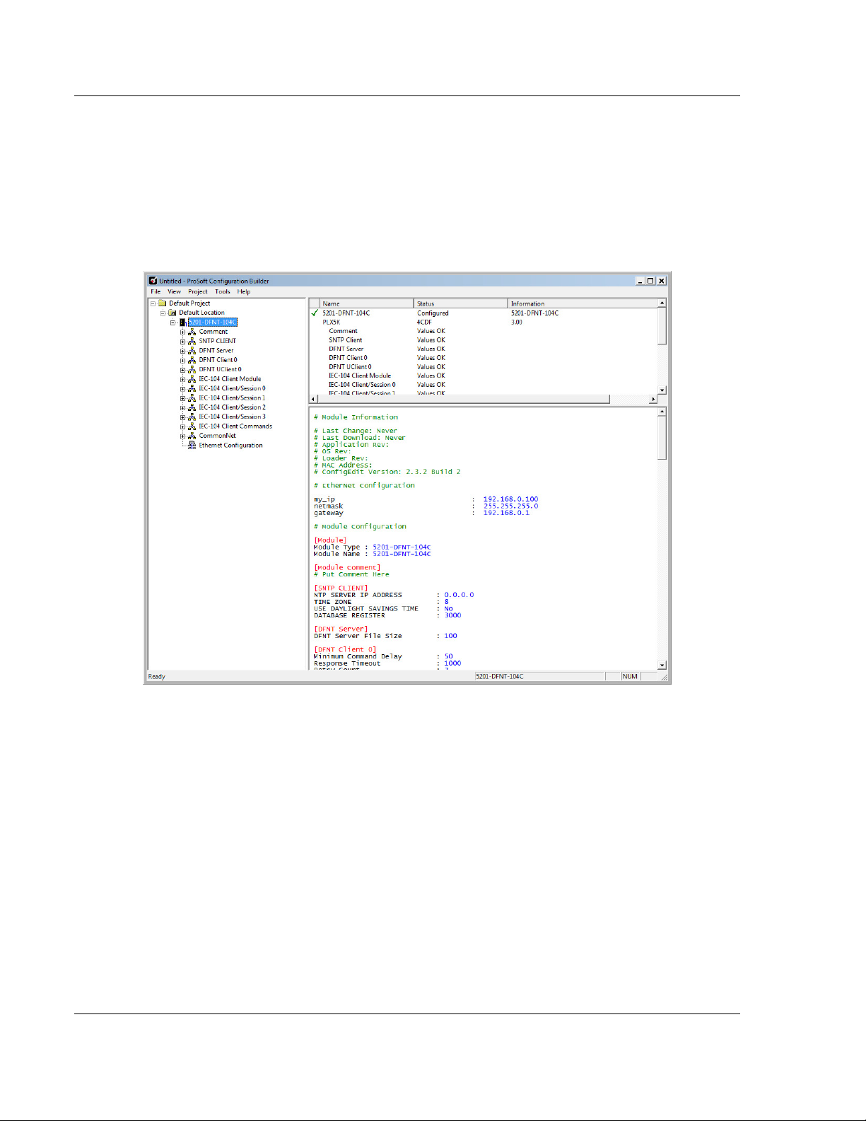
As Seen in PCB
The SNTP driver will compute a new clock value every 5 minutes using the
average value of 10 samples each collected over an approximate 6-second
period. This new value will be used to adjust the clock maintained by the SNTP
driver and used by the application. If a valid database register is specified, the
driver will place the time value into the module's database. The first two registers
will contain the number of seconds and the next two registers will contain the
number of microseconds since January 1, 1970.
A list of some of the common SNTP servers can be obtained at
http://www.ntp.org/
or, http://support.ntp.org/bin/view/Servers/WebHome
Other server lists can be found by searching the World Wide Web for SNTP
Servers.
SNTP Server IP Address
Enter in dotted notation
This parameter sets the IP address of the SNTP server to utilize for time
acquisition. Select an SNTP server with the greatest accuracy that can be
accessed all the time from your network. Setting this IP address to 0.0.0.0
disables SNTP server requests.
Page 18 of 139 ProSoft Technology, Inc.
August 4, 2011
Page 19
104C Version 3 ♦ ProLinx Gateway Configuring the Gateway
IEC 60870-5-104 Client (Firmware v3.xx) Protocol Manual
Time Zone
-11 to 11
This parameter specifies the time zone offset to be used from the UTC time
zone. A value of zero uses UTC time. If the value entered is positive, the time
zone is west of the UTC time zone (for example, Eastern Standard Time is 5). If
the value entered is negative, the time zone is east of the UTC time zone (for
example, Continental Europe is -1).
Use Daylight Savings Time
YES or NO
This parameter specifies if daylight savings time will be used in the time
computation.
Database Register
-1 or 0 to 3996 as an even value
This parameter specifies if the NTP time computed by the driver is to be placed
into the module’s database. If a value of -1 is specified, the time will not be
placed into the database. If the value is between 0 and 3992, the time will be
placed in the database. The first 4 bytes will represent the seconds since
1/1/1970, and the second 4 bytes will represent the number of microseconds. An
even value should be used for the register value in order for the data to be stored
correctly.
2.1.2 [IEC-870-5-104]
This section provides the parameters required for general driver configuration.
Most entries contained within this section are self-explanatory.
ProSoft Technology, Inc. Page 19 of 139
August 4, 2011
Page 20

Configuring the Gateway 104C Version 3 ♦ ProLinx Gateway
Protocol Manual IEC 60870-5-104 Client (Firmware v3.xx)
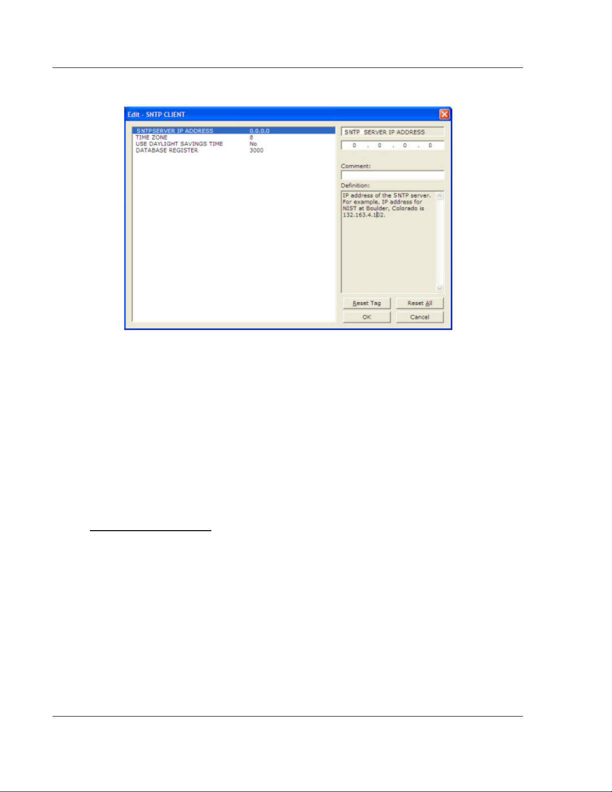
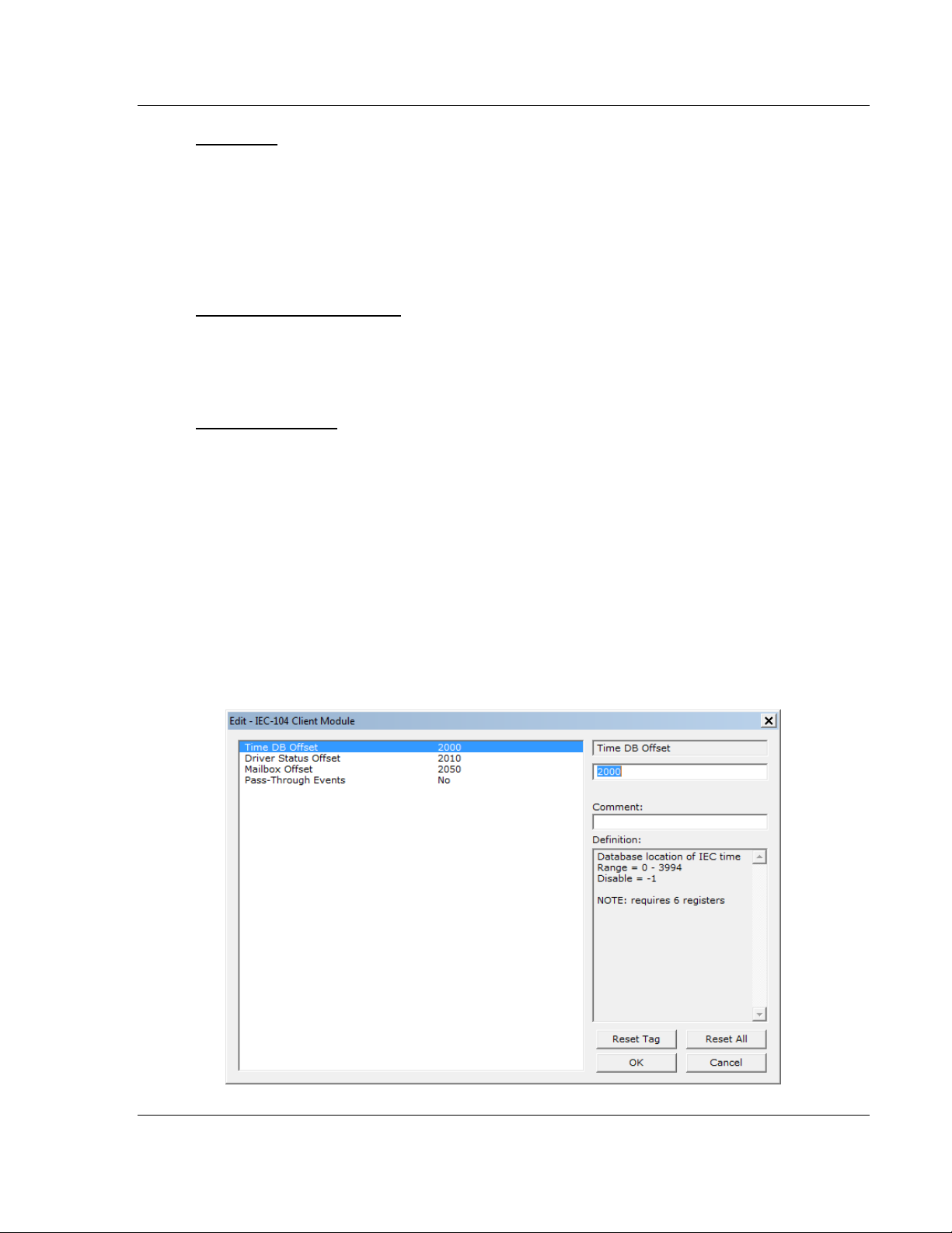
Time DB Offset
-1 or 0 to 3994
This parameter sets the location in the database where the gateway’s 104C
Client date and time will be copied to.
Note: The following table lists the 12-byte data area placed in the database if the Time DB Offset
parameter is set to a value other than -1:
Byte Length Range Description
0 to 1 2 0 to 59,999 Seconds and milliseconds
2 1 0 to 59 Minutes
3 1 0 to 23 Hour
4 1 Reserved
5 1 1 to 31 Day of the month
6 1 1 to 12 Month
7 to 8 2 0 to 65,535 Year (four-digit format, for example 2005)
9 1 Reserved
10 1 0 or 1 Invalid flag (0 = Valid, 1 = Invalid)
11 1 Reserved
Driver Status Offset
0-3982
Database location of general client driver status data
Disable = -1
Refer to section 6.3 (Server Error and Status Data) for the detailed contents of
the status block.
NOTE: requires 18 registers
Mailbox Offset
0 - 3872
Database offset to the mailbox interface area. This feature is applicable to the
5201-DFNT-104C module. The mailbox allows the DFNT driver to request
specific tasks from the 104 driver such as time update and dynamically sending
commands
Disable = -1
Refer to section 4 (Mailbox feature) for further information about the mailbox
functionality.
The mailbox interface requires 128 database registers.
Page 20 of 139 ProSoft Technology, Inc.
August 4, 2011
Page 21
104C Version 3 ♦ ProLinx Gateway Configuring the Gateway
IEC 60870-5-104 Client (Firmware v3.xx) Protocol Manual
Pass-Through Events
This parameter specifies if spontaneous event messages received from the
servers will be passed to the mailbox interface. If the parameter is set to N,
event messages will not be passed to the mailbox interface. If the parameter is
set to Y, the driver will pass all events received to the mailbox interface using
mailbox identifier 9903 & -9903. The Mailbox Interface should be enabled by
setting a valid value for "Mailbox Offset" if this feature is utilized.
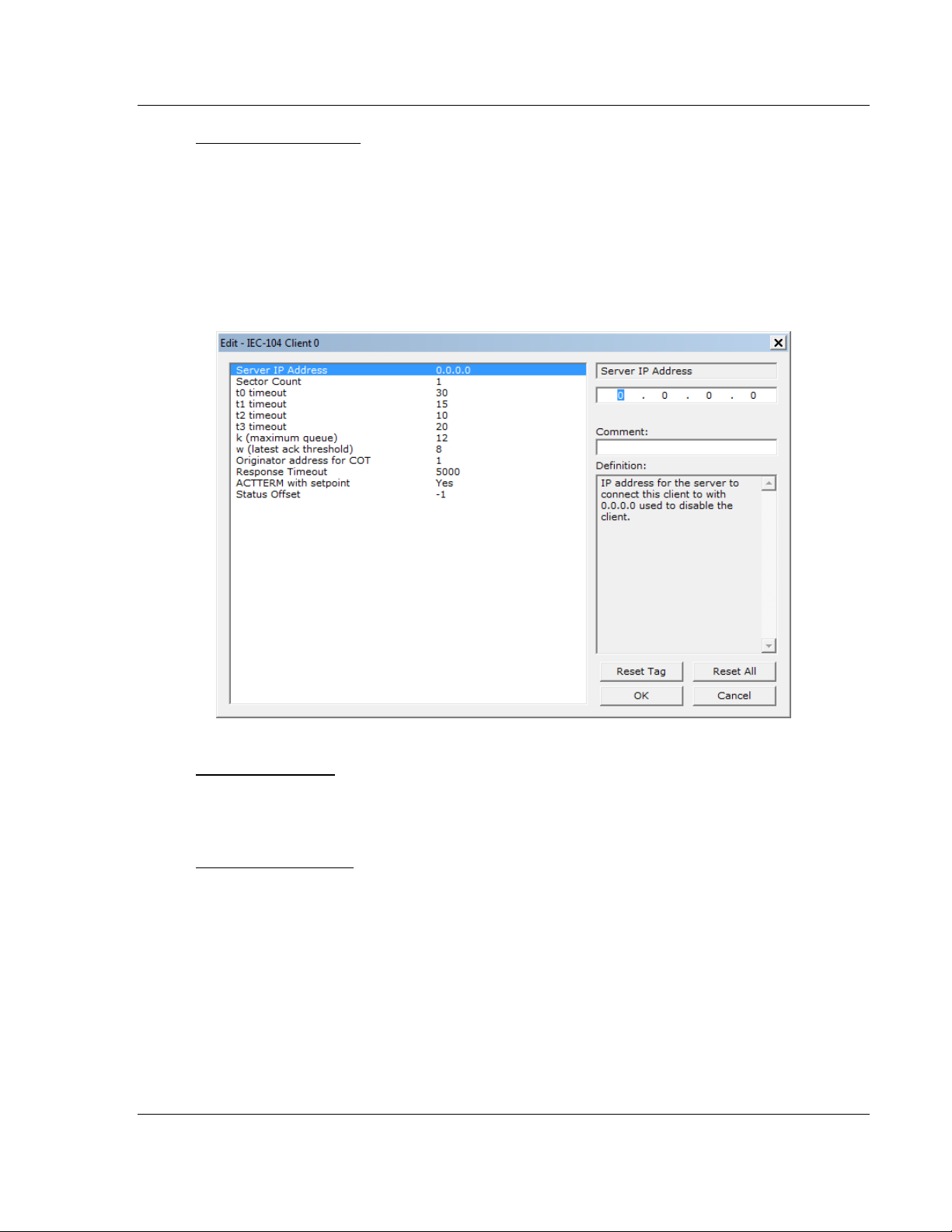
2.1.3 [IEC-60870-5-104 Client x]
Server IP Address
IP address of the remote server that will be connected to this client
Sector Count - 1 to 2
1 to 2
This parameter sets the number of Sectors (separate databases or Multiple
Application Layer ASDU addresses) contained in this Session (controlled
device). This version of the application supports 1 to 2 sectors for each
Client/session.
ProSoft Technology, Inc. Page 21 of 139
August 4, 2011
Page 22

Configuring the Gateway 104C Version 3 ♦ ProLinx Gateway
Protocol Manual IEC 60870-5-104 Client (Firmware v3.xx)
t0 Connection Timeout
1 to 30, default value = 30
This is a timeout value, in seconds, to determine if a connection has been lost
with the remote server. If no traffic from the remote server is received for the
period of time specified by this parameter, the currently open IP socket
connection will be closed. The connection can be re-established by the Client by
opening a new connection.
t1 Timeout Set Value
1 to 255 DEFAULT VALUE = 15
This is the timeout of send or test ASDUs and is in units of seconds. After a
packet is sent from the unit, the server must acknowledge the packet within this
time interval or else the unit will close the connection.
t2 Timeout Set Value
1 to 255 DEFAULT VALUE = 10
This is a timeout of when to send an S-format message to the host to
acknowledge outstanding messages received. This parameter is in units of
seconds and must be less than the value set for t1.
t3 Timeout Set Value
1 to 255 DEFAULT VALUE = 20
This is the timeout to wait on an idle line before the unit will send a TestFr.Act
message. This value is in units of seconds.
k (maximum queue)
1 to 20 DEFAULT VALUE = 6
This parameter specifies the number of unacknowledged messages the unit will
buffer. This parameter must match that in the server. If the set number of buffers
is filled in the unit, no other messages will be sent until the server unit
acknowledges some or all the messages.
w (latest ack threshold)
1 to 20 DEFAULT VALUE = 4
This parameter must match that of the server unit and specifies the number of
messages the gateway will receive before sending an S-format sequence
acknowledge message when no I-format data is ready to send. It is
recommended to set this value to 2/3 the value of k.
Originator address for COT
0 to 255 DEFAULT VALUE = 1
This parameter sets the address to be passed with each message when the COT
Octet Count parameter is set to 2.
Page 22 of 139 ProSoft Technology, Inc.
August 4, 2011
Page 23

104C Version 3 ♦ ProLinx Gateway Configuring the Gateway
IEC 60870-5-104 Client (Firmware v3.xx) Protocol Manual
Response Timeout
0 to 5000 milliseconds DEFAULT VALUE = 5000
This parameter sets the maximum number of milliseconds to wait for a
confirmation from the controlled station to a request from this module to
application level messages.
ACTTERM with Set Point
Y - YES or N - NO
This parameter determines if an ACTTERM (Activation Termination) will be sent.
If the parameter is set to YES, then Set point commands will issue an ACTTERM
when the command is complete. If the parameter is set to NO, ACTCON
(Activation Confirmation) is the last response to a Set point command.
Status Offset
Range -1 to 3956
Database location of client status data
Range = 0 - 3956
Disable = -1
(Refer to the status section for further information about the content of this
section).
NOTE: requires 44 registers
ProSoft Technology, Inc. Page 23 of 139
August 4, 2011
Page 24
Configuring the Gateway 104C Version 3 ♦ ProLinx Gateway
Protocol Manual IEC 60870-5-104 Client (Firmware v3.xx)
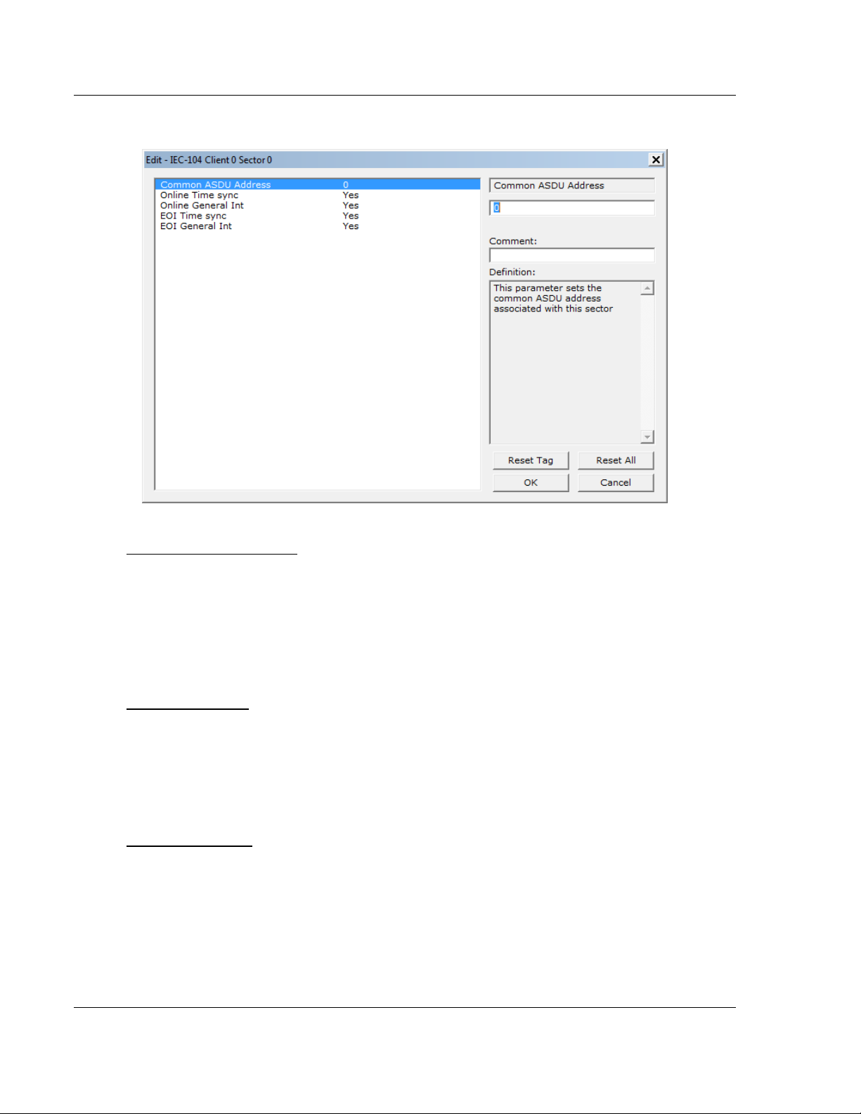
2.1.4 [IEC-60870-5-104 Client x Sector x] Parameters
Common ASDU Address
At the application level, the gateway is identified by the Common ASDU
(Application Service Data Unit) Address. This address must match the CASDU
sent at the server unit. An ASDU is a data unit that transfers information objects
between the Client and the server.
If the gateway sends a message to a different Common ASDU, the server should
ignore the command.
Online Time Sync
Yes or No
This parameter specifies if the sector in the server device will be sent a time
synchronization command when the server device is first recognized as being
online. This should only be used for devices that do not send an EOI message
after initializing.
Online General Int
Yes or No
This parameter specifies if the sector in the server will be sent a general
interrogation command when the unit is first recognized as being online.
Page 24 of 139 ProSoft Technology, Inc.
August 4, 2011
Page 25

104C Version 3 ♦ ProLinx Gateway Configuring the Gateway
IEC 60870-5-104 Client (Firmware v3.xx) Protocol Manual
EOI Time Sync
Yes or No
This parameter specifies if the sector in the server device will be sent a time
synchronization command after this module received an EOI (End of
Initialization) message from the server device.
EOI General Int
Yes or No
This parameter specifies if the sector in the server will be sent a general
interrogation command after this module receives an EOI message from the
controlled unit.
ProSoft Technology, Inc. Page 25 of 139
August 4, 2011
Page 26
Configuring the Gateway 104C Version 3 ♦ ProLinx Gateway
Protocol Manual IEC 60870-5-104 Client (Firmware v3.xx)
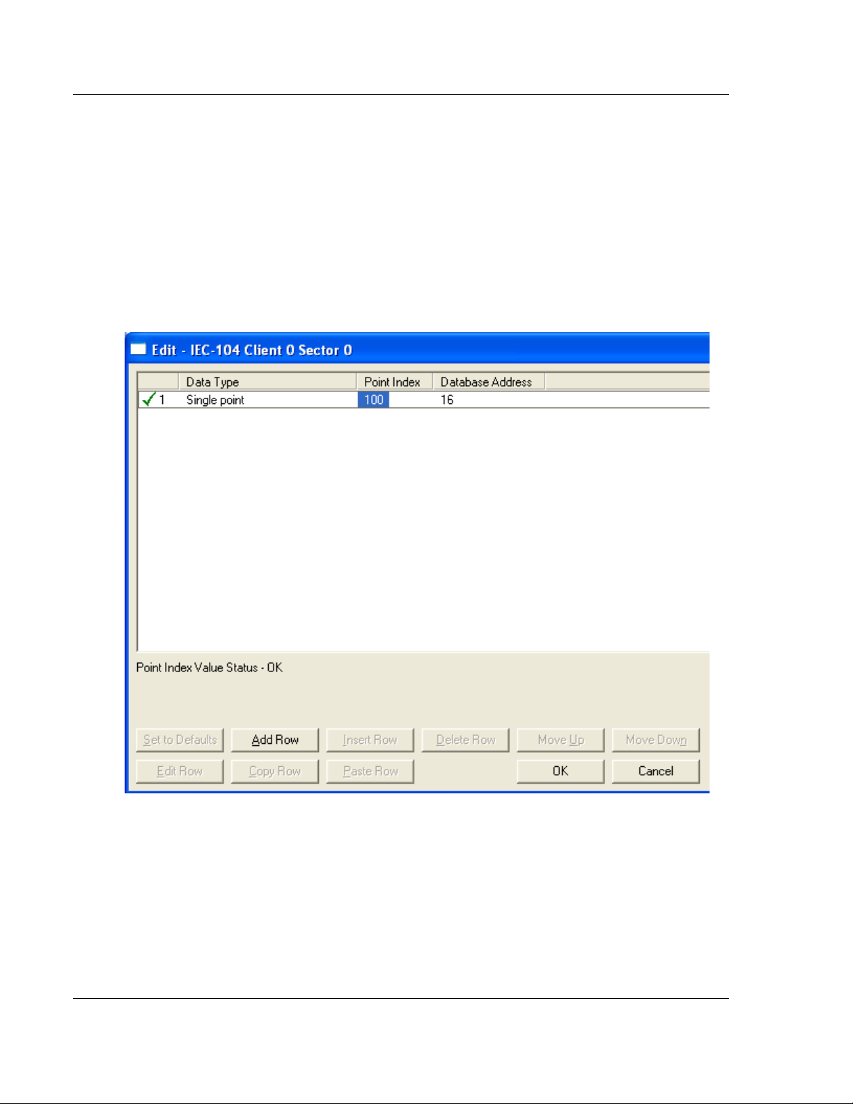
2.1.5 [IEC-60870-5-104 Client x Sector y]
This section allows the user to associate the monitored data points to module
database. These points are sent from the remote server to the module. There
are 3 parameters for each point association that you create: Data Type, Point
Index, Database Address.
The data type must be selected among one of the following supported types. The
Point Index is the Information Object Address which identifies the point in the
network. The Database Address defines the gateway database location on
where the point value will be stored. The database address could be defined as
bit-addressing, byte addressing, word addressing or double-word addressing
depending on the data type.
For additional information on how to set these parameters, see the Reference
chapter of this manual. The following ASDU data types are supported:
Page 26 of 139 ProSoft Technology, Inc.
August 4, 2011
Page 27

104C Version 3 ♦ ProLinx Gateway Configuring the Gateway
IEC 60870-5-104 Client (Firmware v3.xx) Protocol Manual
Monitor Single Point [M_SP_NA]
This section defines the Monitor Single-Point information object database.
Each information object (point) indicates one of two states, 1 = Bit On, 0 = Bit Off.
Each information object is one bit and the DB Address value corresponds to the
bit offset in the gateway memory database.
For additional information on how to set these parameters, see the Reference
chapter of this manual.
Monitor Double Point [M_DP_NA]
Each information object in the database can have one of four possible states, 00
= Intermediate, 01 = Off, 10 = On, and 11 = Intermediate.
Each information object is two bits and the DB Address value corresponds to the
bit offset in the gateway memory database.
Monitor Step Position [M_ST_NA]
Each information object is one 8-bit byte and the DB Address value corresponds
to the byte offset in the gateway memory database.
[M_BO_NA_1 104]
Each information object is four 8-bit bytes (two 16-bit words) and the DB Address
value corresponds to the double-word offset in the gateway memory database.
Monitor Normalized Measured [M_ME_NA]
Each information object is one 16-bit word and the DB Address value
corresponds to the word offset in the gateway memory database.
Monitor Scaled Measured [M_ME_NB]
Each information object is one 16-bit word and the DB Address value
corresponds to the word offset in the gateway memory database.
Monitor Short Floating-Point [M_ME_NC]
Each information object is two 16-bit words and the DB Address value
corresponds to the double-word offset in the gateway memory database.
Monitor Integrated Totals (Counter) [M_IT_NA]
Each information object is two 16-bit words and the DB Address value
corresponds to the double-word offset in the gateway memory database.
ProSoft Technology, Inc. Page 27 of 139
August 4, 2011
Page 28
Configuring the Gateway 104C Version 3 ♦ ProLinx Gateway
Protocol Manual IEC 60870-5-104 Client (Firmware v3.xx)
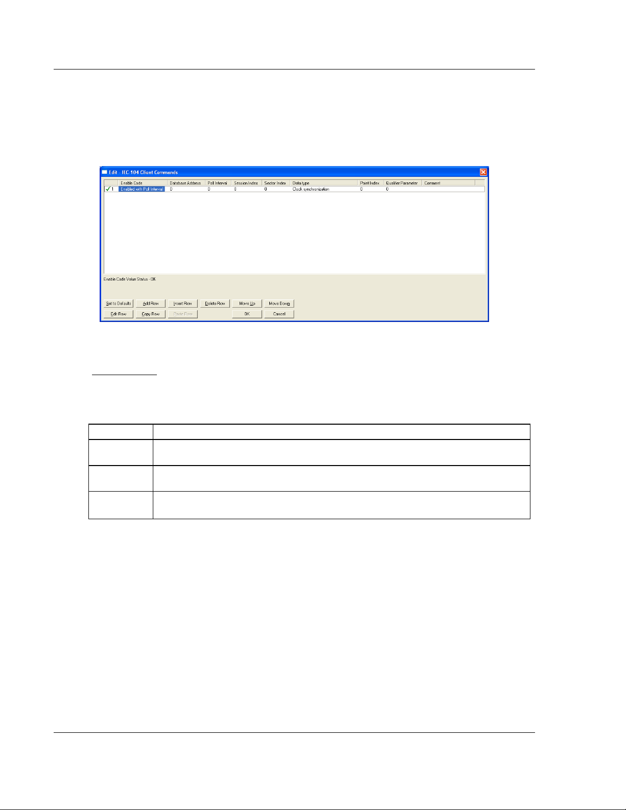
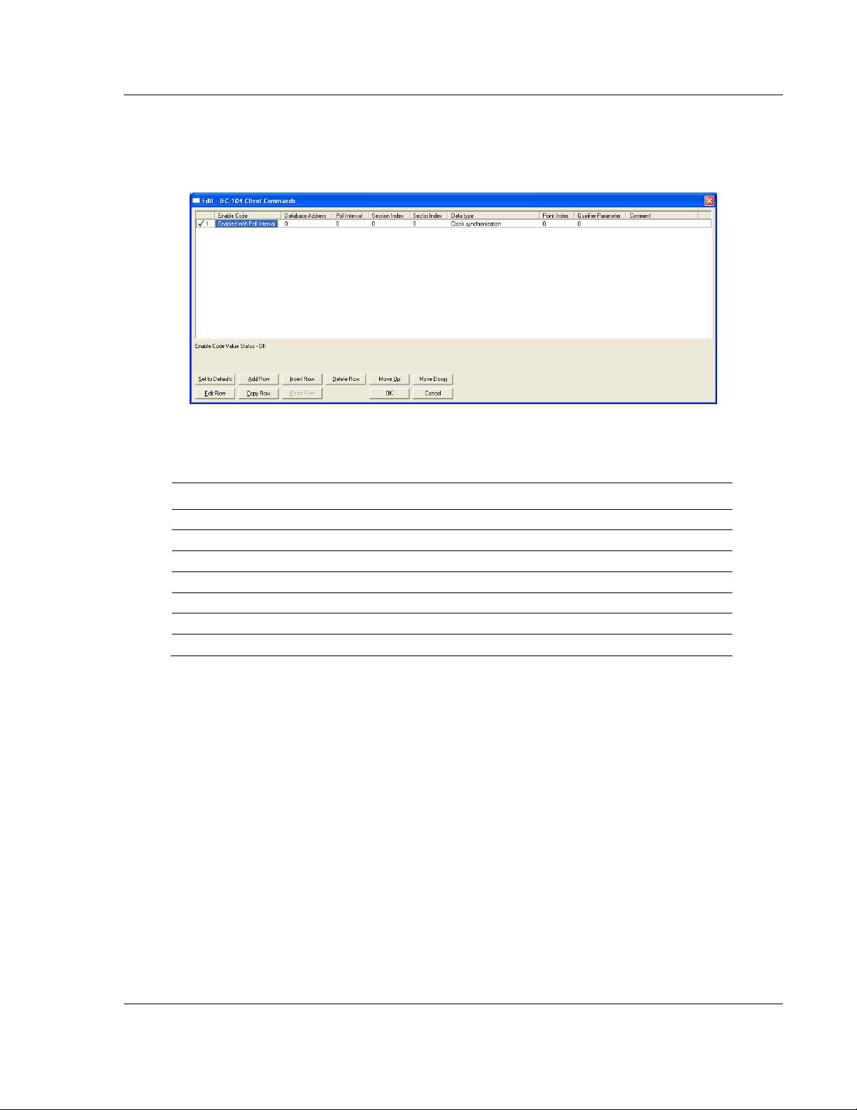
2.1.6 [IEC-60870-5-104 Client Commands]
Each row of this section allows the configuration of one command to be sent to
the remote server. The command can be either a control point (single point,
double-point, etc..) or a general command such as clock synchronization to a
specific client.
The following parameters must be configured for each command:
Enable Code
This field determines when the command will be executed according to the
following codes:
Value Description
Command is disabled and will only execute if enabled from mailbox interface (see mailbox
Disabled
Enabled with
Poll Interval Command will execute no more frequently than the time set in the Poll interval parameter
Conditional
interface for further details)
Command will execute when the last value read in the database differs from the current
value
Page 28 of 139 ProSoft Technology, Inc.
August 4, 2011
Page 29

104C Version 3 ♦ ProLinx Gateway Configuring the Gateway
IEC 60870-5-104 Client (Firmware v3.xx) Protocol Manual
Database Address
The interpretation for the database address parameter will depend on the
selected data type. The database address value is only significant to the control
data types (single point, double-point, etc…).
Examples:
If you select single point command type the database address is interpreted as a
bit-address. For example, a value of 32 means bit 0 of database word 2.
If you select regulating step point command type the database address is
interpreted as a byte-address. For example, a value of 32 means byte 0 of
database word 16.
If you select measured scaled integer command type the database address is
interpreted as a word-address. For example, a value of 32 means database word
32
If you select measured scaled integer command type the database address is
interpreted as a double-word-address. For example, a value of 32 means
database word 16, For the other command types (clock synchronization, read
command, reset process command and test command) you can use the
database address to trigger the command upon data change. However the value
itself is not used within the command.
FIELD DESCRIPTION
This field specifies the location in the module's internal database to associate with
Database
Index used in the command determines addressing of the index as follows:
Type Description DB Index type
---- ----------------------------------- ------------------------------ 45 Single point Command Bit address
46 Double point Command Bit address
47 Regulating Step point Command Byte address
48 Setpoint, normalized point Command Word address
49 Setpoint, scaled point Command Word address
50 Setpoint, short float point Command Double-word address
51 Bitstring (32-bits) point Command Double-word address
100 Group interrogation command *Word address
101 Counter interrogation command *Word address
102 Read command *Word address
103 Clock synchronization command *Word address
105 Reset process command *Word address
107 Test command (IEC-870-5-104 type) *Word address
110 Parameter, normalized measured value Word address
111 Parameter, scaled measured value Word address
112 Parameter, short float value Float (double-word address)
113 Parameter activation command *Word address
*Word address = Value only used to signal when to send event (Enable Code = 2)
the command. The data type
ProSoft Technology, Inc. Page 29 of 139
August 4, 2011
Page 30

Configuring the Gateway 104C Version 3 ♦ ProLinx Gateway
Protocol Manual IEC 60870-5-104 Client (Firmware v3.xx)
Poll Interval
This parameter is used if the Enable Code field is set as Enabled With Poll
Interval. It sets the minimum number of seconds to delay between successive
execution of the command.
Session
This parameter is utilized to associate the command with one of the
sessions/clients defined for the module.
Sector
This parameter is used to associate the command with the proper sector of the
selected session.
Data Type
This parameter is used to set the ASDU data type to be used with the message.
The codes specified are those defined for the IEC-870-5-101 protocol. The
following is a listing of command control data types supported in this module:
Type Description
---- -------------------------------------------------
45 Single point command
46 Double point command
47 Regulating step point command
48 Setpoint, normalized point command
49 Setpoint, scaled point command
50 Setpoint, short float point command
51 Bitstring (32-bits) point command
100 General or group interrogation command
101 Counter interrogation command
102 Read command
103 Clock synchronization command
105 Reset process command
107 Test command (IEC-870-5-104 type)
110 Parameter setting for normalized measured value
111 Parameter setting for scaled measured value
112 Parameter setting for short float value
113 Parameter activation command
Page 30 of 139 ProSoft Technology, Inc.
August 4, 2011
Page 31

104C Version 3 ♦ ProLinx Gateway Configuring the Gateway
IEC 60870-5-104 Client (Firmware v3.xx) Protocol Manual
Point Index
This parameter specifies the Information Object Address in the server device that
corresponds to the command.
Qualifier Parameter
This parameter specifies qualifiers required by the command. This parameter is
dependent on the ASDU data type associated with the command as follows:
SINGLE POINT (45), DOUBLE POINT (46) AND REGULATING STEP (47):
Value:
Single Point Value:
0=Off
1=On
Double Point Value:
0=Not permitted
1=Off
2=On
3=Not Permitted
Regulating Point Value:
0=Not permitted
1=Next step lower if database point is set to -1
2=Next step high if database point set to +1
3=Not Permitted
Qualifier used:
Qualifier Code:
0=No additional definition (slave dependent)
4=Short pulse duration
8=Long pulse duration
12=Persistent output
Select/Execute:
0=Direct execution without select
128=Select executed followed by execute
256=Deselect command
Use Override Flag:
0=Use value in database for value
512=Use override value for state
NORMALIZED (48), SCALED (49) AND SHORT FLOAT (50) SETPOINTS:
Value:
Value read from database for point specified
ProSoft Technology, Inc. Page 31 of 139
August 4, 2011
Page 32

Configuring the Gateway 104C Version 3 ♦ ProLinx Gateway
Protocol Manual IEC 60870-5-104 Client (Firmware v3.xx)
Qualifier used:
0=Direct execution without select
1=Select executed followed by execute
2=Deselect command
32-BITSTRING SETPOINT (51):
Value:
Value read from database for point specified
Qualifier used:
None used
INTERROGATION GROUP COMMAND (100):
Value:
None used for this command with Database Index parameter ignored.
Qualifier used:
0=Not used
1 to 19 = Reserved by standard
20=Station interrogation (global)
21=Interrogation group 1
22=Interrogation group 2
23=Interrogation group 3
24=Interrogation group 4
25=Interrogation group 5
26=Interrogation group 6
27=Interrogation group 7
28=Interrogation group 8
29=Interrogation group 9
30=Interrogation group 10
31=Interrogation group 11
32=Interrogation group 12
33=Interrogation group 13
34=Interrogation group 14
35=Interrogation group 15
36=Interrogation group 16
37 to 63 = Reserved by standard
64 to 255 = Reserved for special use (private range)
COUNTER INTERROGATION GROUP COMMAND (101):
Value:
None used for this command with Database Index parameter ignored.
Qualifier Used:
Counter Interrogation Group:
0=No counter requested
1=Request counter group 1
Page 32 of 139 ProSoft Technology, Inc.
August 4, 2011
Page 33

104C Version 3 ♦ ProLinx Gateway Configuring the Gateway
IEC 60870-5-104 Client (Firmware v3.xx) Protocol Manual
2=Request counter group 2
3=Request counter group 3
4=Request counter group 4
5=Request general counter group
6 to 31 = Reserved by standard
32 to 63 = Reserved for special use (private range)
Freeze/Reset Qualifier:
0=No freeze or reset
64=Counter freeze without reset
128=Counter freeze with reset
192=No freeze with counter reset
READ COMMAND (102):
Value:
No value in database utilized. Data for the Point Index in the slave is requested.
Qualifier used:
None used
CLOCK SYNCHRONIZATION COMMAND (103):
Value:
No value in database utilized.
Qualifier used:
0=Clock synchronization
TEST COMMAND (107=104 STANDARDS):
Value:
No value in database utilized.
Qualifier used:
None used
RESET COMMAND (105):
Value:
No value in database utilized.
Qualifier used:
0=Not used
1=General reset of process
2=Reset pending information with time tag of the event buffer
3 to 127 = Reserved by standard
128 to 255 = Reserved for special use (private range)
ProSoft Technology, Inc. Page 33 of 139
August 4, 2011
Page 34

Configuring the Gateway 104C Version 3 ♦ ProLinx Gateway
Protocol Manual IEC 60870-5-104 Client (Firmware v3.xx)
PARAMETER SETTING FOR NORMALIZED (110), SCALED (111), SHORT FLOAT (112):
Value:
Value from module's database utilized for the parameter
Qualifier used:
Kind of parameter:
0=Not used
1=Threshold value
2=Smoothing factor (filter time constant)
3=Low limit for transmission of measured values
3=High limit for transmission of measured values
5 to 31 = Reserved by standard
32 to 63 = Reserved for special use (private range)
Local parameter change:
0=No change
64=Change
Parameter in operation:
0=Operation
128=Not in operation
PARAMETER ACTIVATION COMMAND (113):
Value:
No database value used with this command
Qualifier used:
Parameter Qualifier:
0=Not used
1=Act/Deact of previously loaded parameters (point index = 0)
2=Act/Deact of the parameter of the point index specified
3=Act/Deact of persistent cyclic or periodic transmission of the addressed object
4 to 127 = Reserved by standard
128 to 255 = Reserved for special use (private range)
Activation Qualifier:
0=Deactivate
256=Activate
Page 34 of 139 ProSoft Technology, Inc.
August 4, 2011
Page 35
104C Version 3 ♦ ProLinx Gateway Configuring the Gateway
IEC 60870-5-104 Client (Firmware v3.xx) Protocol Manual
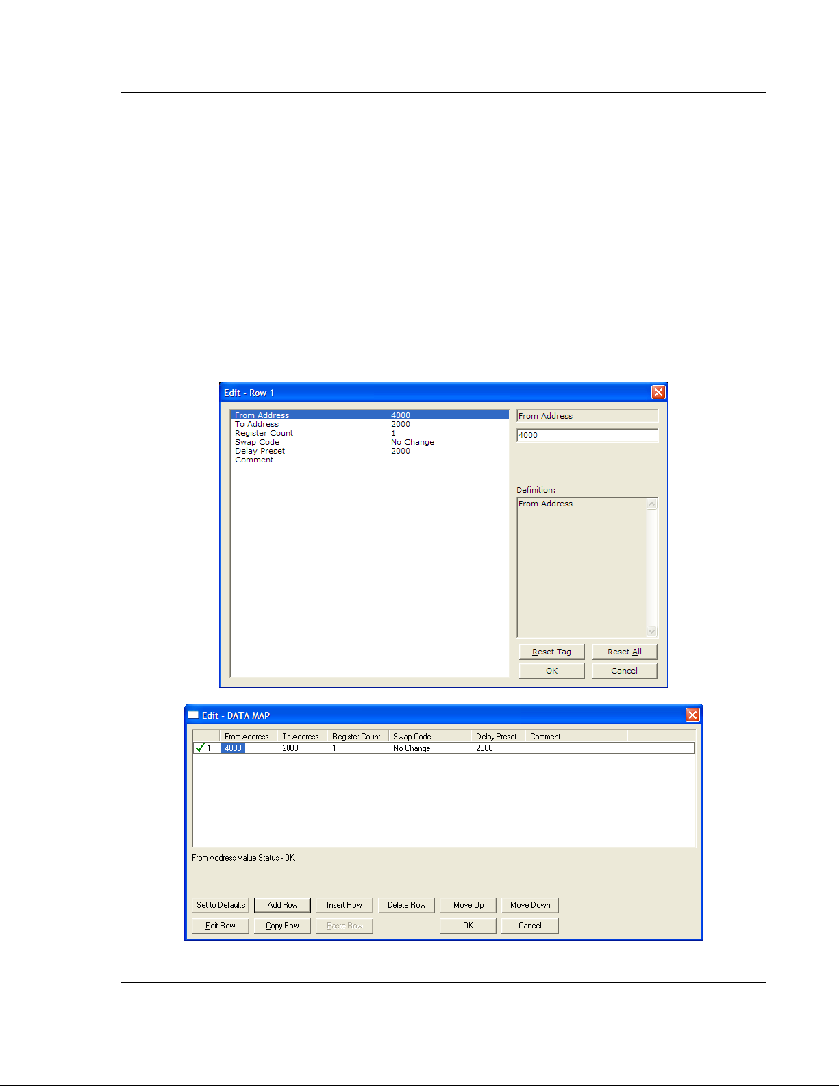
2.2 Using the CommonNet Data Map
The Data Map section allows you to copy data between areas in the gateway's
internal database.
You can copy a maximum of 100 registers per Data Map command, and you can
configure a maximum of 200 separate copy commands.
You can copy data from the error or status tables in upper memory to internal
database registers in the User Data memory area.
You can rearrange the byte and/or word order during the copy process. For
example, by rearranging byte or word order, you can convert floating-point values
to the correct format for a different protocol.
You can also use the Data Map to condense widely dispersed data into one
contiguous data block, making it easier to access.
ProSoft Technology, Inc. Page 35 of 139
August 4, 2011
Page 36

Configuring the Gateway 104C Version 3 ♦ ProLinx Gateway
Protocol Manual IEC 60870-5-104 Client (Firmware v3.xx)
2.2.1 From Address
0 to highest Status Data address
This field specifies the beginning internal database register address for the copy
operation. This address can be any valid address in the User Data Area or the
Status Data Area of the gateway.
2.2.2 To Address
0 to 3999
This parameter specifies the beginning destination register address for the copy
operation. This address must always be within the User Data registers area.
Take care to specify a destination address that will not overwrite data that has
been stored in memory by one of the communication protocols running on the
gateway.
2.2.3 Register Count
1 to 100
This parameter specifies the number of registers to copy.
Page 36 of 139 ProSoft Technology, Inc.
August 4, 2011
Page 37
104C Version 3 ♦ ProLinx Gateway Configuring the Gateway
IEC 60870-5-104 Client (Firmware v3.xx) Protocol Manual
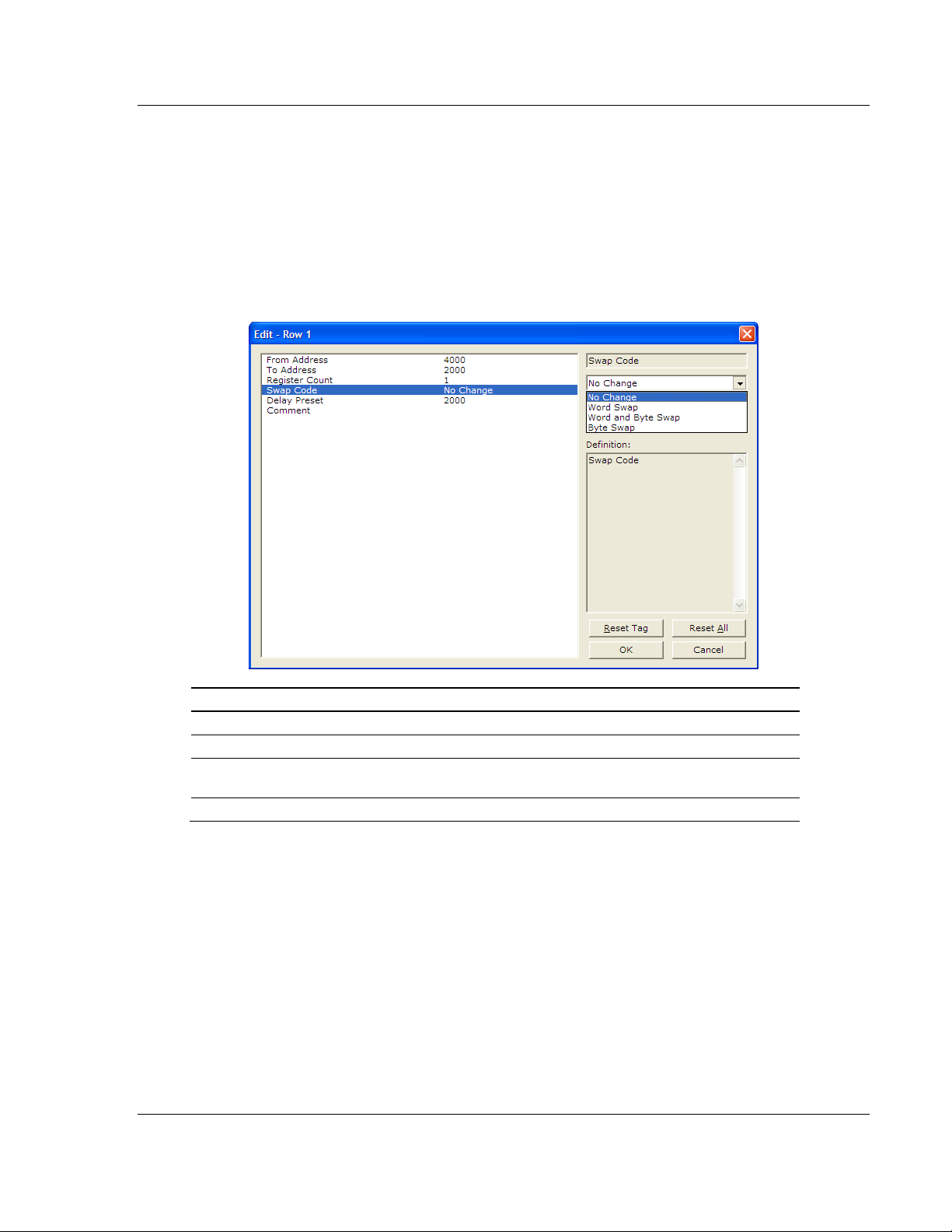
2.2.4 Swap Code
NO C
HANGE
You may need to swap the order of the bytes in the registers during the copy
process in order to change the alignment of bytes between dissimilar protocols.
This parameter is helpful when dealing with floating-point or other multi-register
values, as there is no standard method of storage of these data types in slave
devices.
The following table defines the values and their associated operations:
, W
ORD SWAP
, W
ORD AND BYTE SWAP
, B
YTE SWAP
Swap Code Description
No Swap No change is made in the byte ordering (1234 = 1234)
Word Swap The words are swapped (1234=3412)
Word and
Byte Swap
Bytes The bytes in each word are swapped (1234=2143)
The words are swapped, then the bytes in each word are swapped (1234=4321)
ProSoft Technology, Inc. Page 37 of 139
August 4, 2011
Page 38

Configuring the Gateway 104C Version 3 ♦ ProLinx Gateway
Protocol Manual IEC 60870-5-104 Client (Firmware v3.xx)
2.2.5 Delay Preset
This parameter sets an interval for each Data Map copy operation. The value you
put for the Delay Preset is not a fixed amount of time. It is the number of firmware
scans that must transpire between copy operations.
The firmware scan cycle can take a variable amount of time, depending on the
level of activity of the protocol drivers running on the ProLinx gateway and the
level of activity on the gateway's communication ports. Each firmware scan can
take from 1 to several milliseconds to complete. Therefore, Data Map copy
operations cannot be expected to happen at regular intervals.
If multiple copy operations (several rows in the Data map section) happen too
frequently or all happen in the same update interval, they could delay the process
scan of the gateway protocols, which could result in slow data updates or missed
data on communication ports. To avoid these potential problems, you should set
the Delay Preset to different values for each row in the Data Map section and set
them to higher, rather than lower, numbers.
For example, Delay Preset values below 1000 could begin to cause a noticeable
delay in data updates through the communication ports. And you should not set
all Delay Presets to the same value. Instead, use different values for each row in
the Data Map such as 1000, 1001, and 1002 or any other different Delay Preset
values you like. This will prevent the copies from happening concurrently and
prevent possible process scan delays.
Page 38 of 139 ProSoft Technology, Inc.
August 4, 2011
Page 39
104C Version 3 ♦ ProLinx Gateway Configuring the Gateway
IEC 60870-5-104 Client (Firmware v3.xx) Protocol Manual
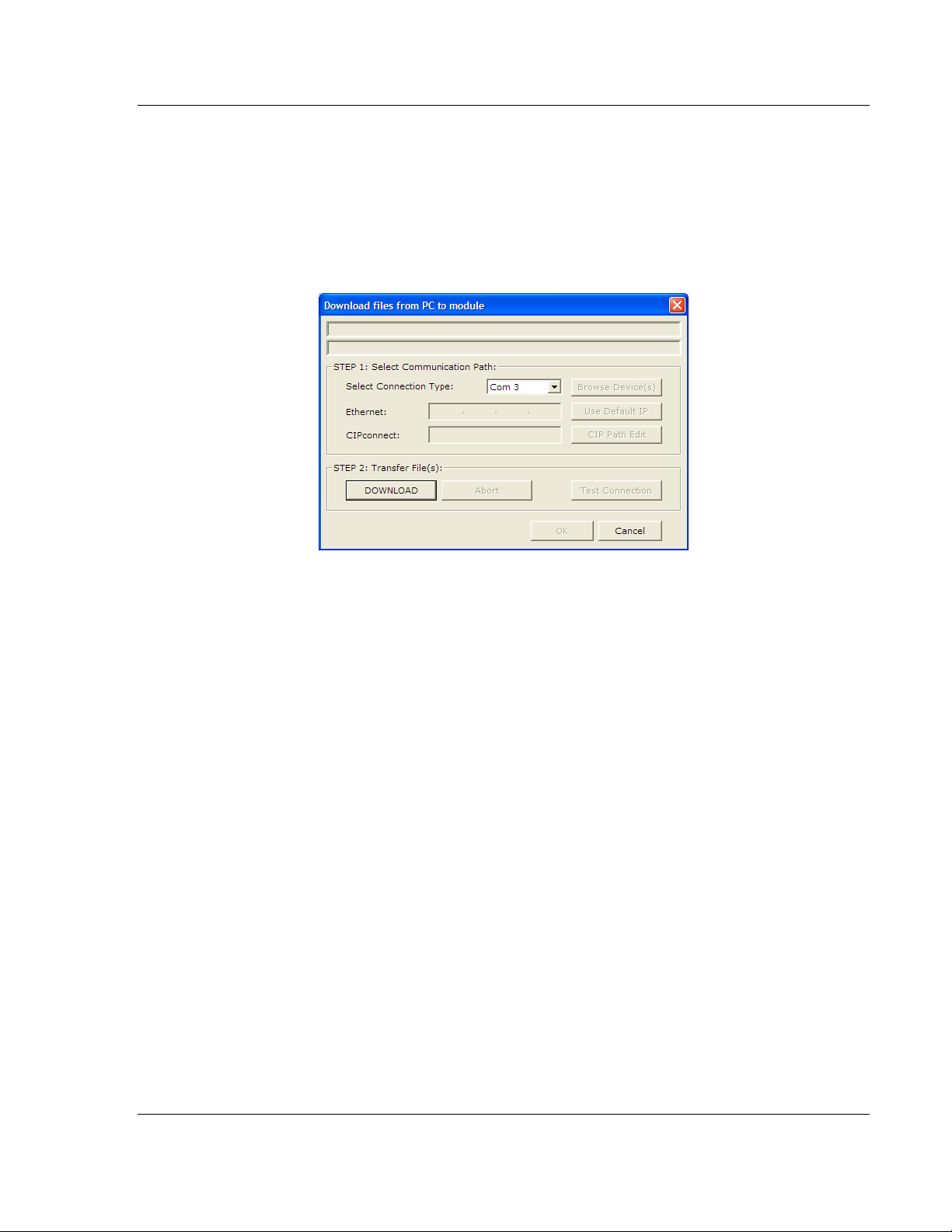
2.3 Downloading a File from PC to the Module
1 Use a null-modem serial cable to connected the serial COM port on your PC
and the Debug/Configuration serial port on the gateway.
2 Open the P
3 On the M
scans for communication ports on your PC. When the scan is complete, the
Download dialog box opens.
ROJECT
ODULE
menu, and then choose M
menu, choose D
OWNLOAD.
Wait while ProSoft Configuration
ODULE
.
4 Select the
5 Click the D
PORT
to use for the download.
OWNLOAD
button.
ProSoft Technology, Inc. Page 39 of 139
August 4, 2011
Page 40
Configuring the Gateway 104C Version 3 ♦ ProLinx Gateway
Protocol Manual IEC 60870-5-104 Client (Firmware v3.xx)
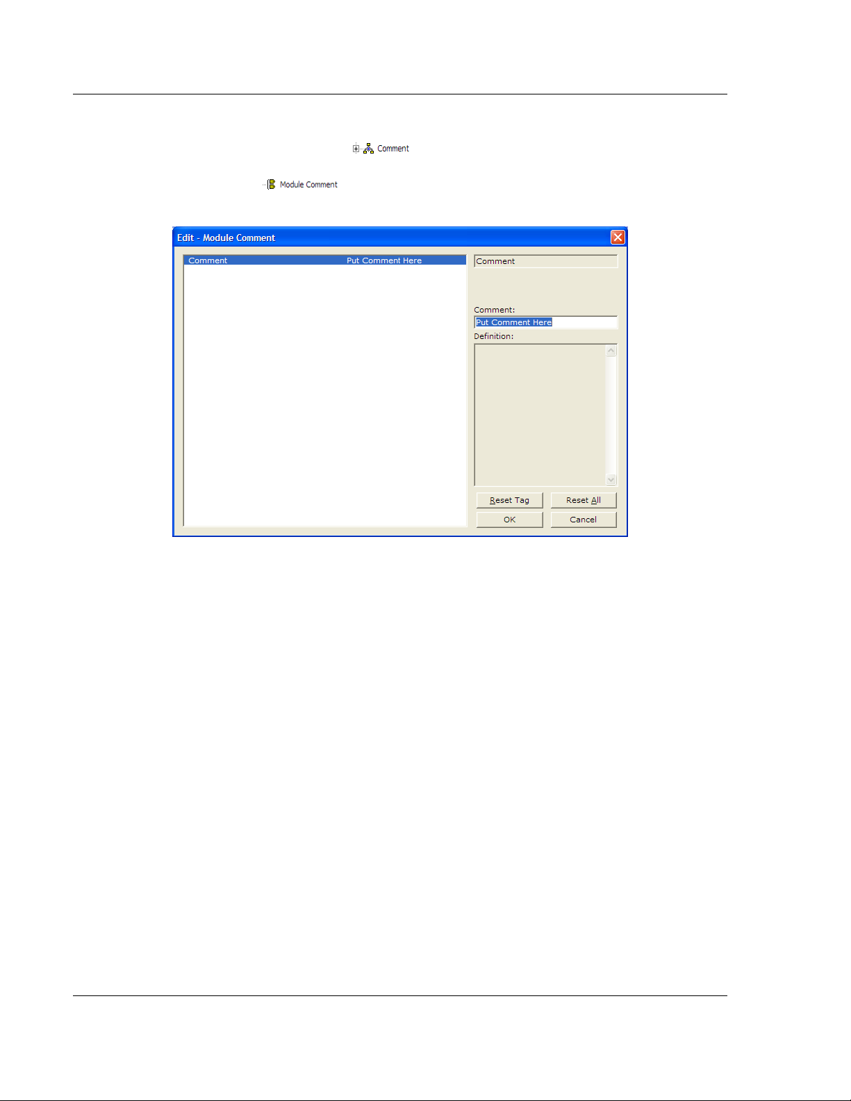
2.4 Creating Optional Comment Entries
1 Click the [+] to the left of the icon to expand the module
comments.
2 Double-click the icon. The Edit - Module Comment dialog box
appears.
3 Enter your comment and click OK to save your changes.
Page 40 of 139 ProSoft Technology, Inc.
August 4, 2011
Page 41

104C Version 3 ♦ ProLinx Gateway Configuring the Gateway
IEC 60870-5-104 Client (Firmware v3.xx) Protocol Manual
2.5 Printing a Configuration File
1 Select the module icon, and then click the right mouse button to open a
shortcut menu.
2 On the shortcut menu, choose V
View Configuration window.
3 In the View Configuration window, open the F
This action opens the Print dialog box.
4 In the Print dialog box, choose the printer to use from the drop-down list,
select printing options, and then click OK.
IEW CONFIGURATION
ILE
menu, and choose P
. This action opens the
RINT.
ProSoft Technology, Inc. Page 41 of 139
August 4, 2011
Page 42

Configuring the Gateway 104C Version 3 ♦ ProLinx Gateway
Protocol Manual IEC 60870-5-104 Client (Firmware v3.xx)
Page 42 of 139 ProSoft Technology, Inc.
August 4, 2011
Page 43

104C Version 3 ♦ ProLinx Gateway IEC-60870-5-104 Protocol Implementation
IEC 60870-5-104 Client (Firmware v3.xx) Protocol Manual
3 IEC-60870-5-104 Protocol Implementation
In This Chapter
Module Address .................................................................................... 44
Monitor Direction and Control Direction: Information Object Definition .. 46
Using Monitor Points ............................................................................. 49
Using Control (Command) Information Objects ..................................... 57
The intent of this section is to provide a quick understanding of how the 104
gateway implements the IEC-60870-5-104 protocol, without going into complex
details of the specification.
The IEC-60870-5-104 protocol applies to telecontrol equipment and data
transmission systems for monitoring and controlling geographically widespread
processes. This protocol is similar to the IEC-60870-5-101 protocol, with the
addition of TCP/IP as the transport mechanism.
Any application with the IEC-60870-5-104 protocol consists of a Client
(Controlling Station) and one or more servers (Controlled Stations). The Client
constantly monitors and controls the data from each server in the TCP/IP
network.
ProSoft Technology, Inc. Page 43 of 139
August 4, 2011
Page 44

IEC-60870-5-104 Protocol Implementation 104C Version 3 ♦ ProLinx Gateway
Protocol Manual IEC 60870-5-104 Client (Firmware v3.xx)
3.1 Module Address
The 104C Module gateway is identified at transport level using the IP Address.
3.1.1 IP Address
The 104C Module gateway is identified by a unique IP address on the TCP/IP
network. You must edit the WATTCP.CFG configuration file (or use the
configuration tool) to enter a valid IP address. The following example lists the
default contents of the WATTCP.CFG file:
In this example, the 104C Module gateway is identified by IP address
192.168.0.250 in the IEC-60870-5-104 network, with a netmask (subnet mask) of
255.255.255.0 and a default gateway address of 192.168.0.1.
Remote Server Identification
The remote server is identified first by its IP address which you can enter through
the Client X section:
Page 44 of 139 ProSoft Technology, Inc.
August 4, 2011
Page 45

104C Version 3 ♦ ProLinx Gateway IEC-60870-5-104 Protocol Implementation
IEC 60870-5-104 Client (Firmware v3.xx) Protocol Manual
You may configure up to four remote servers to be communicating
simultaneously with the module.
You must also identify the Common ASDU Address in the server. This value is
identified through the Client X Sector Y section. Each server can be associated
with up to two sectors with distinct Common ASDU Addresses. The Commons
ASDU address must be greater than 0.
ProSoft Technology, Inc. Page 45 of 139
August 4, 2011
Page 46

IEC-60870-5-104 Protocol Implementation 104C Version 3 ♦ ProLinx Gateway
Protocol Manual IEC 60870-5-104 Client (Firmware v3.xx)
3.2 Monitor Direction and Control Direction: Information Object
Definition
The protocol specification defines two directions of data transmission: Monitor
direction and Control direction.
Monitor Direction: The direction of transmission from a server to the Client
(gateway)
Control Direction: The direction of transmission from the Client (gateway) to a
server
The data that is transferred from a server to a Client is known as Monitor
information objects (or Monitor points). The data that is transferred from a Client
to a server is known as Control information objects (or Control points).
The 104C Module contains an internal database of 4000 16-bit words. You must
associate the Monitor and Control information objects to database addresses in
the 104C Module. To configure the information objects for the 104C Module,
follow these steps:
1 Calculate the number of Monitor and Control information objects for the
application. The total number of monitor points must be equal or less than
1000. The total number of control points (commands) must be equal or less
than 500 points.
2 Calculate the 104C Module database regions that are required for the
application, based on the number of Monitor and Control information objects.
Define two separate regions. Remember that each data type stores a
different quantity of data (for example, M_SP_NA uses one bit, M_ST_NA
uses one byte, and so on).
3 Configure each information object within its 104C Module database region.
Page 46 of 139 ProSoft Technology, Inc.
August 4, 2011
Page 47

104C Version 3 ♦ ProLinx Gateway IEC-60870-5-104 Protocol Implementation
IEC 60870-5-104 Client (Firmware v3.xx) Protocol Manual
4 Make sure that the other parts of your application correctly update the
gateway database regions associated with the configured 104C data types,
as shown in the following illustration.
ProSoft Technology, Inc. Page 47 of 139
August 4, 2011
Page 48
IEC-60870-5-104 Protocol Implementation 104C Version 3 ♦ ProLinx Gateway
Protocol Manual IEC 60870-5-104 Client (Firmware v3.xx)
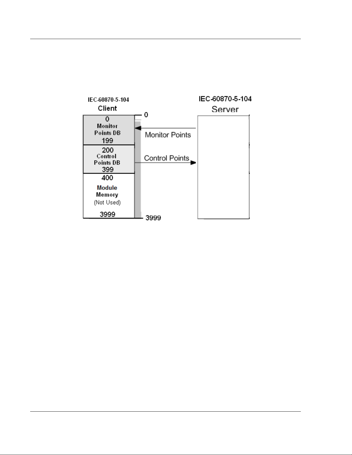
All information objects must be configured in the correct location in the 104C
Module database in order to be properly updated by other parts of the
application. Keep the data types separated by configuring the Control information
objects and Monitor information objects in separate areas of the 104C Module
database. The following illustration shows an example configuration:
In this example, all Monitor information objects are located between database
addresses 0 and 199, and all Control information objects are located between
address 200 and 399.
Page 48 of 139 ProSoft Technology, Inc.
August 4, 2011
Page 49

104C Version 3 ♦ ProLinx Gateway IEC-60870-5-104 Protocol Implementation
IEC 60870-5-104 Client (Firmware v3.xx) Protocol Manual
3.3 Using Monitor Points
The following monitor points are supported by the 104C Module gateway:
Symbol Description Data Size in
M_SP_NA Monitored Single-Points 1 bit Bit
M_DP_NA Monitored Double-Points 2 bits Bit
M_ST_NA Monitored Step Position Points 1 byte Byte
M_BO_NA Monitored 32-Bit Bitstring Points 2 words Double word
M_ME_NA Monitored Normalized Measured Points 1 word Word
M_ME_NB Monitored Scaled Measured Points 1 word Word
M_ME_NC Monitored Short Floating-Point Measured
Points
M_IT_NA Monitored Integrated Totals 2 words Double word
Each monitor point is identified by its Information Object Address or Point # Index
(it should be unique for each Common ASDU Address in the network). For each
monitor point, configure the following parameters:
Point # - The information object address of the point. It identifies the point in the
network.
DB Address - The database location in the 104C Module gateway associated
with the point. You must associate each point to a database address in the 104C
Module gateway. The interpretation of this parameter depends on the point type
configured. For example, for an M_SP_NA point, this value represents the bit
address. For a M_ME_NA point, this value represents the word address.
Addressing
Database
2 words Double word
Type
3.3.1 Monitor Information Objects Addressing
As discussed before, the Monitor information objects must be configured in a
database area in the 104C Module gateway.
The Monitor ASDUs are described in the following table.
ASDU Type Data Size Addressing Type
M_SP_NA 1 bit Bit
M_DP_NA 2 bits Bit
M_ST_NA 1 byte Byte
M_BO_NA 2 words Double word
M_ME_NA 1 word Word
M_ME_NB 1 word Word
M_ME_NC 2 words Double word
M_IT_NA 2 words Double word
ProSoft Technology, Inc. Page 49 of 139
August 4, 2011
Page 50
IEC-60870-5-104 Protocol Implementation 104C Version 3 ♦ ProLinx Gateway
Protocol Manual IEC 60870-5-104 Client (Firmware v3.xx)
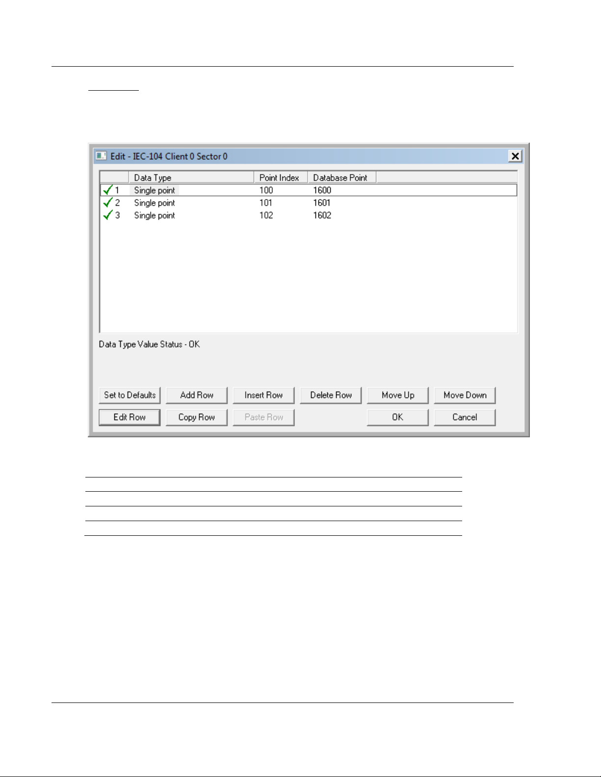
M_SP_NA
A Monitor Single-Point information object occupies one binary bit and uses bit
addressing. For example, if you configured the following information objects as
shown:
The following table describes how these information objects would be stored in
the gateway:
Inf. Object Address Module Database Address
100 Bit 0 of word 100 (Bit address 1600)
101 Bit 1 of word 100 (Bit address 1601)
102 Bit 2 of word 100 (Bit address 1602)
Page 50 of 139 ProSoft Technology, Inc.
August 4, 2011
Page 51
104C Version 3 ♦ ProLinx Gateway IEC-60870-5-104 Protocol Implementation
IEC 60870-5-104 Client (Firmware v3.xx) Protocol Manual
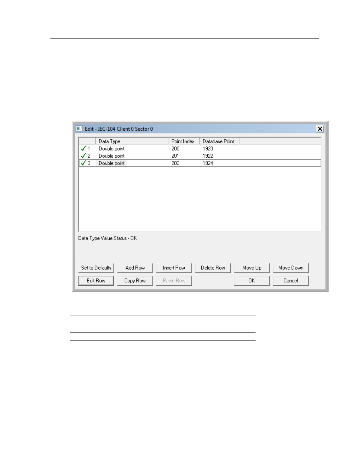
M_DP_NA
A Monitor Double-Point information object occupies two bits and uses bit
addressing. It typically represents the ON/OFF states where:
00 = Undefined or invalid
01 = OFF
10 = ON
11 = Undefined or invalid
If you configured the following information objects as shown:
The following table describes how these information objects would be stored in
the gateway memory database.
Inf. Object Address Module Database Address
200 Bit 0 & 1 of word 120 (Bit address 1920 & 1921)
201 Bit 2 & 3 of word 120 (Bit address 1922 &1923)
202 Bit 4 & 5 of word 120 (Bit address 1924 & 1925)
ProSoft Technology, Inc. Page 51 of 139
August 4, 2011
Page 52
IEC-60870-5-104 Protocol Implementation 104C Version 3 ♦ ProLinx Gateway
Protocol Manual IEC 60870-5-104 Client (Firmware v3.xx)
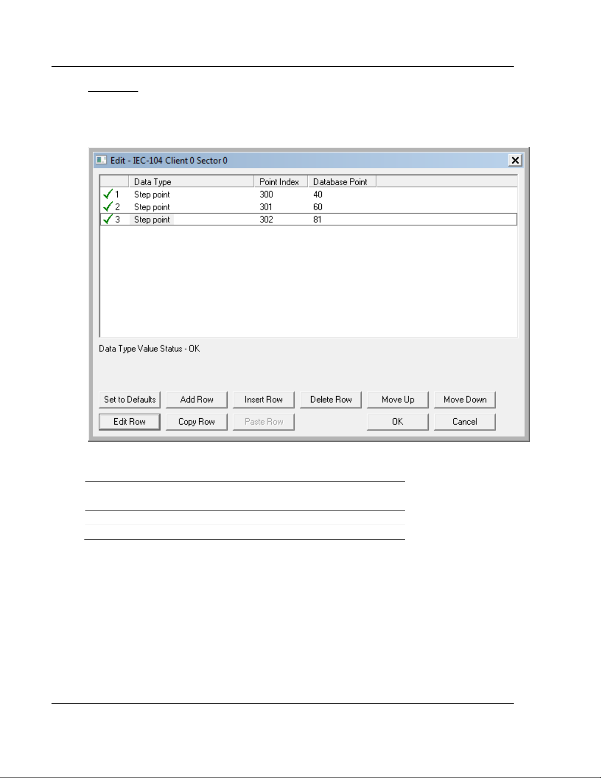
M_ST_NA
A Monitor Step Position information object occupies one byte and uses byte
addressing.
For example, if you configured the following information objects:
The following table describes how these information objects would be stored in
the gateway.
Inf. Object Address Module Database Address
300 Low byte of word 20 (Byte address 40)
301 Low byte of word 30 (Byte address 60)
302 High byte of word 40 (Byte address 81)
Page 52 of 139 ProSoft Technology, Inc.
August 4, 2011
Page 53

104C Version 3 ♦ ProLinx Gateway IEC-60870-5-104 Protocol Implementation
IEC 60870-5-104 Client (Firmware v3.xx) Protocol Manual
M_BO_NA
A Monitor 32-Bit Bitstring information object occupies two words and uses
double-word addressing.
For example, if you configured the following information objects:
The following table describes how these information objects would be stored in
the gateway memory database.
Inf. Object Address Module Database Address
600 Words 2000 and 2001 (Double-word address 1000)
601 Words 2002 and 2003 (Double-word address 1001)
602 Words 2004 and 2005 (Double-word address 1002)
ProSoft Technology, Inc. Page 53 of 139
August 4, 2011
Page 54
IEC-60870-5-104 Protocol Implementation 104C Version 3 ♦ ProLinx Gateway
Protocol Manual IEC 60870-5-104 Client (Firmware v3.xx)
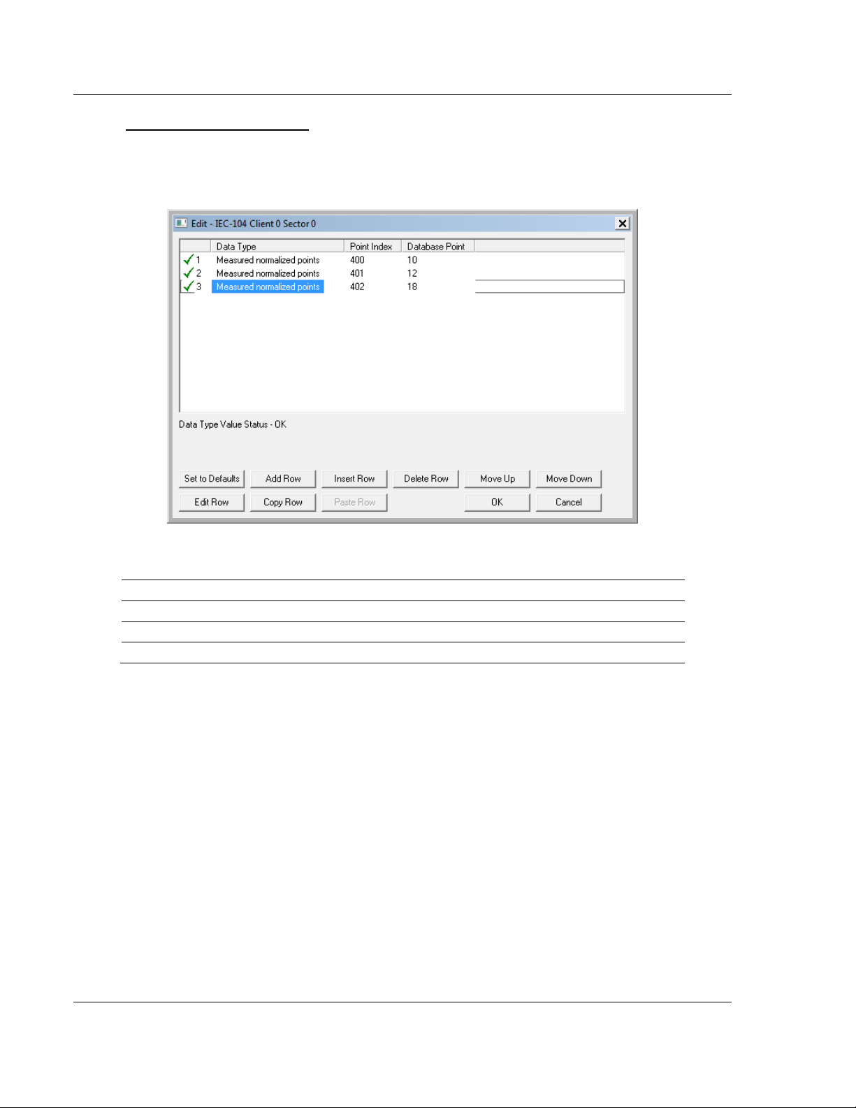
M_ME_NA and M_ME_NB
A Monitor Normalized Measured information object or Monitor Scaled Measured
information object occupies one word and uses word addressing.
For example, if you configured the following information objects:
The following table describes how these information objects would be stored in
the gateway.
Inf. Object Address Module Database Address
400 Word 10 (Word address 10)
401 Word 12 (Word address 12)
402 Word 18 (Word address 18)
Page 54 of 139 ProSoft Technology, Inc.
August 4, 2011
Page 55

104C Version 3 ♦ ProLinx Gateway IEC-60870-5-104 Protocol Implementation
IEC 60870-5-104 Client (Firmware v3.xx) Protocol Manual
Monitor Normalized Measured information objects use a data representation
defined by the protocol specification to represent fractional decimal values. The
following table describes the value for each bit as a reciprocal power of two (2),
that is two (2) raised to the power of a negative exponent (-1 through -15). Bit 15
is the Sign Bit.
Bit 15 14 13 12 11 10 9 8 7 6 5 4 3 2 1 0
Value
Hex(h)
Decimal
4000h
0.5
2000h
0.25
1000h
0.125
6000h
0.75
3210h
0.395751953125
800
400
200
100
80
Sign
4000h
2-1
2000h
2-2
1000h
2-3
h
2-4
h
2-5
h
2-6
h
2-7
h
2-8
40
h
2-9
0 1 0 0 0 0 0 0 0 0 0 0 0 0 0 0
0 0 1 0 0 0 0 0 0 0 0 0 0 0 0 0
0 0 0 1 0 0 0 0 0 0 0 0 0 0 0 0
0 1 1 0 0 0 0 0 0 0 0 0 0 0 0 0
0 0 1 1 0 0 1 0 0 0 0 1 0 0 0 0
20
h
2
10
h
-10
-11
2
8h
2
4h
2h
-12
-13
2
1h
-14
-15
2
2
Examples:
A value of 4000hex (only Bit 14 set, all others clear) is interpreted as 0.5 decimal
A value of 2000hex (only Bit 13 set, all others clear) is interpreted as 0.25
decimal
A value of 1000hex (only Bit 12 set, all others clear) is interpreted as 0.125
decimal
... and so on until...
A value of 0001hex (Only Bit 0 set, all others clear) is interpreted as
0.000030517578125
Therefore, the actual data values transmitted may be any combination of the
decimal values for any given bit pattern.
ProSoft Technology, Inc. Page 55 of 139
August 4, 2011
Page 56
IEC-60870-5-104 Protocol Implementation 104C Version 3 ♦ ProLinx Gateway
Protocol Manual IEC 60870-5-104 Client (Firmware v3.xx)
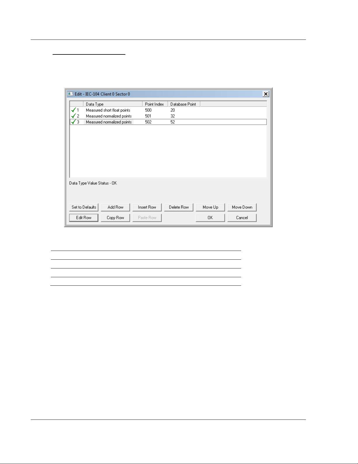
M_ME_NC and M_IT_NA
The Monitor Short Floating-Point Measured Value and Monitor Integrated Totals
information objects occupy two words with double-word addressing.
For example, if you configured the following information objects:
The following table describes how these information objects would be stored in
the gateway.
Inf. Object Address Module Database Address
500 Words 40 and 41 (Double-word address 20)
501 Words 64 and 65 (Double-word address 32)
502 Word 104 and 105 (Double-word address 52)
Page 56 of 139 ProSoft Technology, Inc.
August 4, 2011
Page 57
104C Version 3 ♦ ProLinx Gateway IEC-60870-5-104 Protocol Implementation
IEC 60870-5-104 Client (Firmware v3.xx) Protocol Manual
3.4 Using Control (Command) Information Objects
In order to configure the control points please refer to the Client Command
section. Refer to section 2.1.6 for further information about each command field.
The 104C gateway supports the following Control information objects for data
transfer:
ASDU Type Information Object Description
C_SC_NA Control Single Command
C_DC_NA Control Double Command
C_RC_NA Control Regulating Step Command
C_BO_NA Control 32-Bit Bitstring Command
C_SE_NA Control Normalized Value Set Point Command
C_SE_NB Control Scaled Value Set Point Command
C_SE_NC Control Short Floating-Point Value Set Point Command
In addition to these the module also supports generic commands to request
specific tasks from the remote server such as clock synchronization.
Each Control information object is identified by its Information Object Address.
For each Control information object, configure the following parameters:
Point Index - This is the Information Object Address of the information object. It
identifies the information object in the network. This address must be unique for
each sector (Common ASDU Address) in the network.
DB Address - This is the database location in the 104C v3 gateway associated
with the information object. The database address interpretation may be bitaddress, byte-address, word-address, double-word-address depending on the
ASDU type. Refer to the following section for further information:
ProSoft Technology, Inc. Page 57 of 139
August 4, 2011
Page 58

IEC-60870-5-104 Protocol Implementation 104C Version 3 ♦ ProLinx Gateway
Protocol Manual IEC 60870-5-104 Client (Firmware v3.xx)
3.4.1 Control Information Objects Addressing
You must associate each control information object to a database address in the
gateway. The interpretation of the DB Address parameter in the configuration
tables depends on the ASDU configured and the type of addressing associated
with that ASDU.
ASDU Type Data Size Addressing Type
C_SC_NA 1 bit Bit
C_DC_NA 2 bits Bit
C_RC_NA 1 byte Byte
C_BO_NA 2 words Double word
C_SE_NA 1 word Word
C_SE_NB 1 word Word
C_SE_NC 2 words Double word
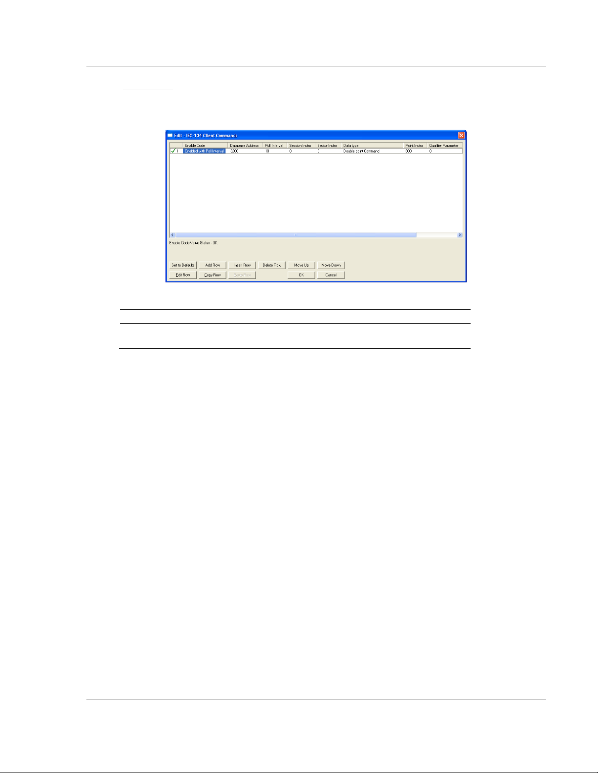
C_SC_NA
A Control Single Command information object occupies one bit and uses bit
addressing. For example, if you configure the following information objects:
These information objects would be used as follows:
Inf. Object Address Module Database Address
800 Bit 0 of word 200 to hold the Control bit (Bit address
3200)
Page 58 of 139 ProSoft Technology, Inc.
August 4, 2011
Page 59
104C Version 3 ♦ ProLinx Gateway IEC-60870-5-104 Protocol Implementation
IEC 60870-5-104 Client (Firmware v3.xx) Protocol Manual
C_DC_NA
A Control Double Command information object occupies two bits and uses bit
addressing. For example, if you configure the following information objects:
These information objects would be used as follows:
Inf. Object Address Module Database Address
800 Bits 0 and 1 of word 200 to hold the Control bits (Bit
addresses 3200 and 3201)
ProSoft Technology, Inc. Page 59 of 139
August 4, 2011
Page 60

IEC-60870-5-104 Protocol Implementation 104C Version 3 ♦ ProLinx Gateway
Protocol Manual IEC 60870-5-104 Client (Firmware v3.xx)
C_RC_NA
A Control Regulating Step Command information object occupies one byte and
uses byte addressing.
For example, if you configured the following information objects:
The following table describes how these information objects would be stored in
the module database.
Inf. Object Address Module Database Address
1000 Low Byte of word 250 (Byte address 500)
Page 60 of 139 ProSoft Technology, Inc.
August 4, 2011
Page 61

104C Version 3 ♦ ProLinx Gateway IEC-60870-5-104 Protocol Implementation
IEC 60870-5-104 Client (Firmware v3.xx) Protocol Manual
C_BO_NA
A Control 32-Bit Bitstring Command information object occupies two words and
uses double-word addressing.
For example, if you configured the following information objects:
These information objects would be used as follows:
Inf. Object Address Module Database Address
3100 Words 3000 and 3001 (Double-word address 1500)
ProSoft Technology, Inc. Page 61 of 139
August 4, 2011
Page 62

IEC-60870-5-104 Protocol Implementation 104C Version 3 ♦ ProLinx Gateway
Protocol Manual IEC 60870-5-104 Client (Firmware v3.xx)
C_SE_NA and C_SE_NB
The Control Normalized Value Set Point Command information object and the
Control Scaled Value Set Point Command information object use one word with
word addressing. For example, if you configured the following information
objects:
The following table describes how these information objects would be used.
Inf. Object Address Module Database Address
1100 Word 2000 (Word address 2000)
The Control Normalized Measured information objects use a data representation
defined by the protocol specification to represent fractional decimal values. The
following table describes the value for each bit as a reciprocal power of two (2),
that is two (2) raised to the power of a negative exponent (-1 through -15). Bit 15
is the Sign Bit.
Bit 15 14 13 12 11 10 9 8 7 6 5 4 3 2 1 0
Value
Hex(h)
Decimal
4000h
0.5
2000h
0.25
1000h
0.125
6000h
0.75
3210h
0.395751953125
800
400
200
100
80
Sign
4000h
2-1
2000h
2-2
1000h
2-3
h
2-4
h
2-5
h
2-6
h
2-7
h
2-8
40
h
2-9
0 1 0 0 0 0 0 0 0 0 0 0 0 0 0 0
0 0 1 0 0 0 0 0 0 0 0 0 0 0 0 0
0 0 0 1 0 0 0 0 0 0 0 0 0 0 0 0
0 1 1 0 0 0 0 0 0 0 0 0 0 0 0 0
0 0 1 1 0 0 1 0 0 0 0 1 0 0 0 0
20
h
2
10
h
-10
-11
2
8h
2
4h
2h
-12
-13
2
1h
-14
2
2
-15
Page 62 of 139 ProSoft Technology, Inc.
August 4, 2011
Page 63

104C Version 3 ♦ ProLinx Gateway IEC-60870-5-104 Protocol Implementation
IEC 60870-5-104 Client (Firmware v3.xx) Protocol Manual
Examples:
A value of 4000hex (only Bit 14 set, all others clear) is interpreted as 0.5 decimal
A value of 2000hex (only Bit 13 set, all others clear) is interpreted as 0.25
decimal
A value of 1000hex (only Bit 12 set, all others clear) is interpreted as 0.125
decimal
... and so on until...
A value of 0001hex (Only Bit 0 set, all others clear) is interpreted as
0.000030517578125
Therefore, the actual data values transmitted may be any combination of the
decimal values for any given bit pattern.
C_SE_NC
A Control Short Floating-Point Value Set Point Command information object
occupies two words and uses double-word addressing.
For example, if you configured the following information objects:
The following table describes how these information objects would be stored in
the gateway:
Inf. Object Address Module Database Address
1300 Words 2600 and 2601 (Double-word address 1300)
ProSoft Technology, Inc. Page 63 of 139
August 4, 2011
Page 64
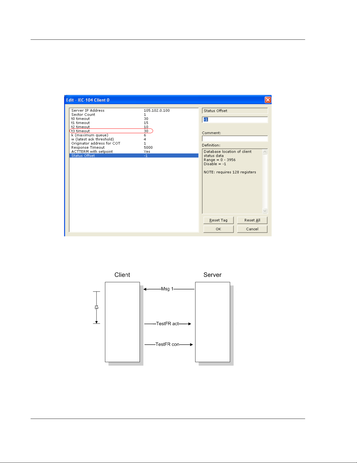
IEC-60870-5-104 Protocol Implementation 104C Version 3 ♦ ProLinx Gateway
Protocol Manual IEC 60870-5-104 Client (Firmware v3.xx)
3.4.2 TESTFR Requests
Connections that are unused (but opened) may be periodically tested in both
directions by sending test messages (TESTFR=act), which are confirmed by the
receiving station sending TESTFR=con messages. The gateway can be
configured to periodically send this message using the following parameter:
In the example above, the gateway would send a TESTFR.ACT message 30
seconds after receiving the last message:
Page 64 of 139 ProSoft Technology, Inc.
August 4, 2011
Page 65
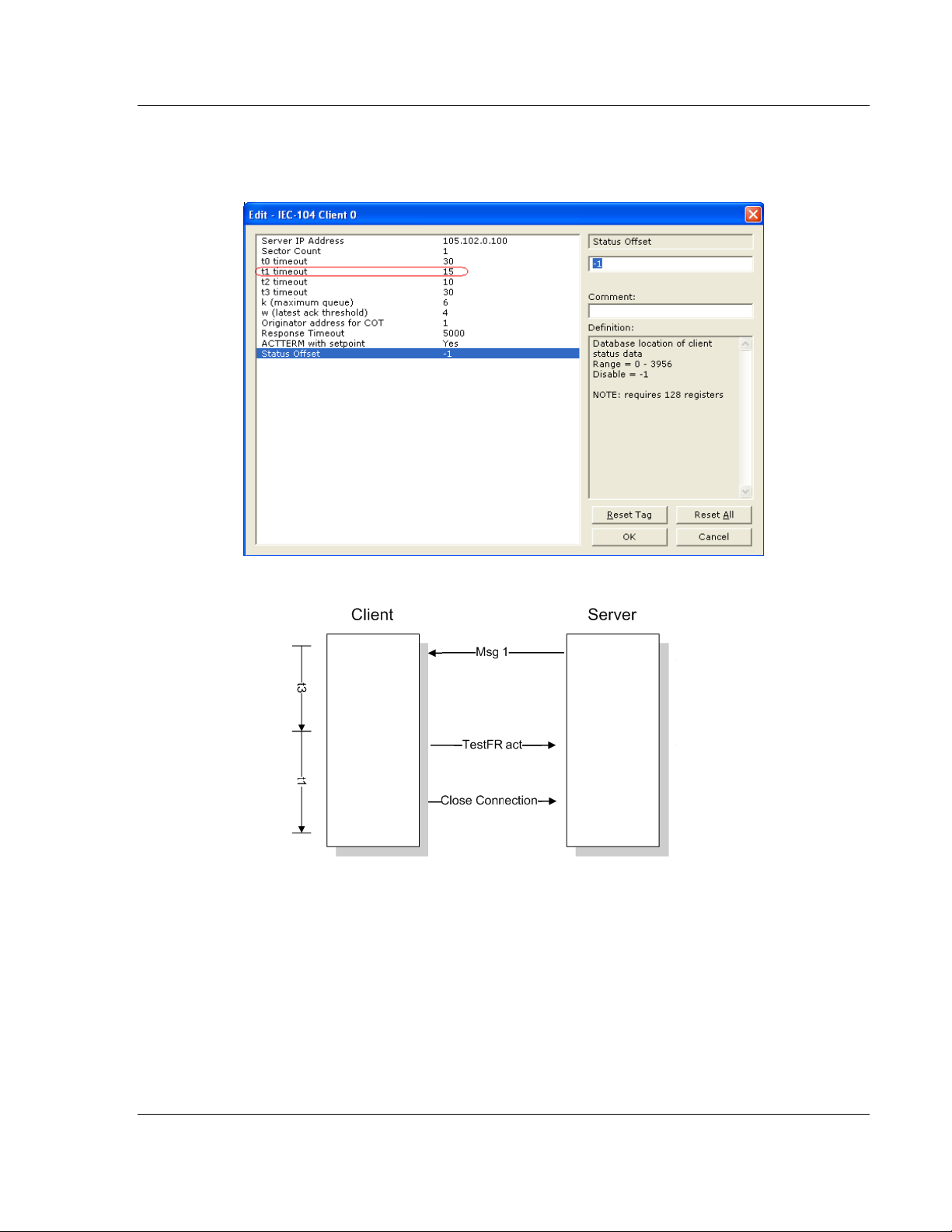
104C Version 3 ♦ ProLinx Gateway IEC-60870-5-104 Protocol Implementation
IEC 60870-5-104 Client (Firmware v3.xx) Protocol Manual
If the gateway does not receive the TESTFR.con message within a certain
amount of time, it will time out and close the connection. You can configure the
timeout period using the following parameter:
ProSoft Technology, Inc. Page 65 of 139
August 4, 2011
Page 66

IEC-60870-5-104 Protocol Implementation 104C Version 3 ♦ ProLinx Gateway
Protocol Manual IEC 60870-5-104 Client (Firmware v3.xx)
Page 66 of 139 ProSoft Technology, Inc.
August 4, 2011
Page 67
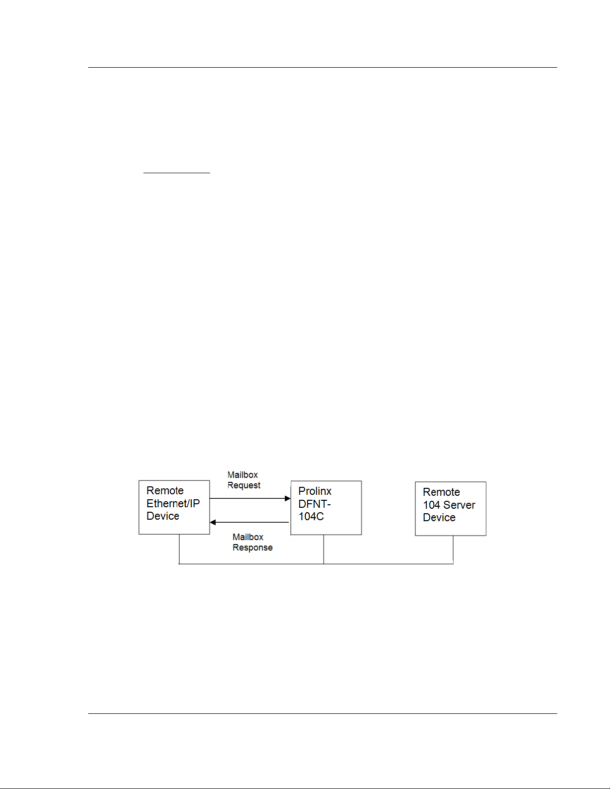
104C Version 3 ♦ ProLinx Gateway Mailbox Feature (x201-DFNT-104C)
IEC 60870-5-104 Client (Firmware v3.xx) Protocol Manual
4 Mailbox Feature (x201-DFNT-104C)
In This Chapter
User Constructed Command Mailbox (9901) ........................................ 70
Command Control Block Mailbox (9902) ............................................... 72
Event Messages from Outstations Mailbox (9903) ................................ 73
General Gateway Status Mailbox (9250) ............................................... 76
Client X Status Data Mailbox (9251) ..................................................... 78
Command List Error Data Mailbox (9950) ............................................. 81
Get Gateway Time Mailbox (9970) ........................................................ 83
Set Gateway Time Mailbox (9971) ........................................................ 85
Reset Status Data Mailbox (9997) ......................................................... 87
Coldboot Mailbox (9998/9999) .............................................................. 88
The 5201-DFNT-104C module supports the mailbox feature. It allows the
Ethernet/IP (DFNT) remote device to request specific tasks from the module by
writing a data block request to the module database. The module will perform the
request and then update the mailbox response area in the database.
ProSoft Technology, Inc. Page 67 of 139
August 4, 2011
Page 68
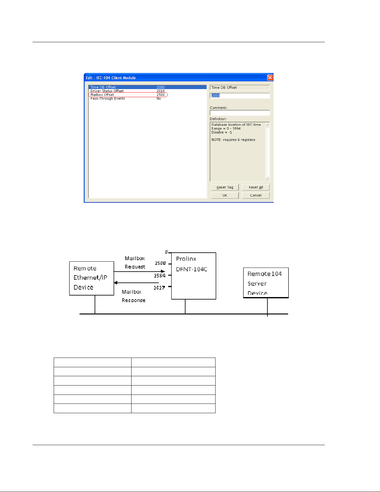
Mailbox Feature (x201-DFNT-104C) 104C Version 3 ♦ ProLinx Gateway
Protocol Manual IEC 60870-5-104 Client (Firmware v3.xx)
The start of the mailbox area is configured through the Mailbox Offset parameter
in the IEC-104 Client Module section as follows:
The mailbox area requires a 128-word database area. The first 64 words are
used for the mailbox request area received from the remote Ethernet/IP device.
The last 64 words are reserved for the mailbox response built by the gateway
module. So for the example above:
In the mailbox request area the first and last words are reserved for the mailbox
ID. Once the module recognizes a new mailbox ID (same mailbox ID) into these
registers it will process the mailbox request starting from the second register:
Offset Description
0 Mailbox ID
1 Start of mailbox request
… …
62 End of mailbox request
63 Mailbox ID
Page 68 of 139 ProSoft Technology, Inc.
August 4, 2011
Page 69

104C Version 3 ♦ ProLinx Gateway Mailbox Feature (x201-DFNT-104C)
IEC 60870-5-104 Client (Firmware v3.xx) Protocol Manual
The same applies for the mailbox response. The module builds the mailbox
response and updates the mailbox ID according to the originating request:
Offset Description
0 Mailbox ID
1 Start of mailbox response
… …
62 End of mailbox response
63 Mailbox ID
The following mailboxes are supported by the module:
Block Range Descriptions
±9901 User Constructed Command to add to command queue
±9902 Command Control Block (Add command to Command Queue)
±9903 Event Messages from Outstations
±9250 General Module Status
±9251 Client X Status Data
±9950 Command List Error data
±9970 Get 104 client driver's time
±9971 Set 104 client driver's time
±9997 Reset status data
9998 Cold boot Confirmation
9999 Cold Boot Request
The purpose for the mailbox supporting a positive and negative value is so the
remote device can trigger consecutive requests for the same mailbox by
switching the value between positive and negative. For example, to request 3
consecutive Get Module time the block ID could be switched as +9970, -9970,
+9970.
ProSoft Technology, Inc. Page 69 of 139
August 4, 2011
Page 70

Mailbox Feature (x201-DFNT-104C) 104C Version 3 ♦ ProLinx Gateway
Protocol Manual IEC 60870-5-104 Client (Firmware v3.xx)
4.1 User Constructed Command Mailbox (9901)
This mailbox allows the remote Ethernet/IP device to dynamically build
commands to be sent to the remote 104 server for one time. Up to 10 commands
can be built for one block.
Mailbox Request
Word Offset in
Block
0 Mailbox ID This field contains the identification code of -9901 or
1 Command Count This field defines the number of user commands
2 to 7 Command #1 Data required to build the user defined command in
8 to 13 Command #2 Data required to build the user defined command in
14 to 19 Command #3 Data required to build the user defined command in
20 to 25 Command #4 Data required to build the user defined command in
26 to 31 Command #5 Data required to build the user defined command in
32 to 37 Command #6 Data required to build the user defined command in
38 to 43 Command #7 Data required to build the user defined command in
44 to 49 Command #8 Data required to build the user defined command in
50 to 55 Command #9 Data required to build the user defined command in
56 to 61 Command #10 Data required to build the user defined command in
62 Spare Not Used
63 Mailbox ID This field contains the identification code of -9901 or
Data Field(s) Description
9901 for the block.
contained in the block. The valid range for the field
is 1 to 10.
the command queue.
the command queue.
the command queue.
the command queue.
the command queue.
the command queue.
the command queue.
the command queue.
the command queue.
the command queue.
9901 for the block.
Page 70 of 139 ProSoft Technology, Inc.
August 4, 2011
Page 71

104C Version 3 ♦ ProLinx Gateway Mailbox Feature (x201-DFNT-104C)
IEC 60870-5-104 Client (Firmware v3.xx) Protocol Manual
The following fields are used for each word record in the command list:
Word Offset Definitions Description
0 Database Index Address in module to associate with the
1 Session Index Session index defined in the module to
2 Sector Index Sector index for session as defined in the
3 Data Type ASDU data type associated with the
4 Point Index Information object address for the point on
5 Qualifier Qualifier as defined for the command list.
command
associate with the command (0 to 3).
module (0 or 1).
command.
which command operates.
This parameter is data type dependent.
Mailbox Response
Word Offset in
Block
0 Mailbox ID This field contains the identification code of -9901 or
1 Command Count This field defines the number of user commands
2 to 62 Spare Not Used
63 Mailbox ID This field contains the identification code of -9901 or
Data Field(s) Description
9901 for the block.
added to the command queue
9901 for the block.
ProSoft Technology, Inc. Page 71 of 139
August 4, 2011
Page 72

Mailbox Feature (x201-DFNT-104C) 104C Version 3 ♦ ProLinx Gateway
Protocol Manual IEC 60870-5-104 Client (Firmware v3.xx)
4.2 Command Control Block Mailbox (9902)
This mailbox allows the remote Ethernet /IP device to dynamically enable for one
time a 104C configured command that is disabled. Up to 60 commands can be
enabled simultaneously in one block.
Mailbox Request
Word Offset
in Block
0 Mailbox ID This field contains the value of -9902 or 9902
1 Command count This field contains the number of commands to
2 to 61 Command
Data Field(s) Description
Numbers to
enable
identifying the enable command to the module.
enable in the command list. Valid values for this
field are 1 to 60.
These 60 words of data contain the command
numbers in the command list to enable. The
commands in the list will be placed in the
command queue for immediate processing by
the module. The first command in the list has
an index of 0.
62 Spare Not Used
63 Mailbox ID This field contains the value of -9902 or 9902
identifying the enable command to the module.
Mailbox Response
Word Offset
in Block
0 Mailbox ID This field contains the value of -9902 or 9902
1 Command count This field contains the number of commands
2 to 62 Spare Not Used
63 Mailbox ID This field contains the value of -9902 or 9902
Data Field(s) Description
identifying the enable command to the module.
added to the command queue.
identifying the enable command to the module.
Page 72 of 139 ProSoft Technology, Inc.
August 4, 2011
Page 73
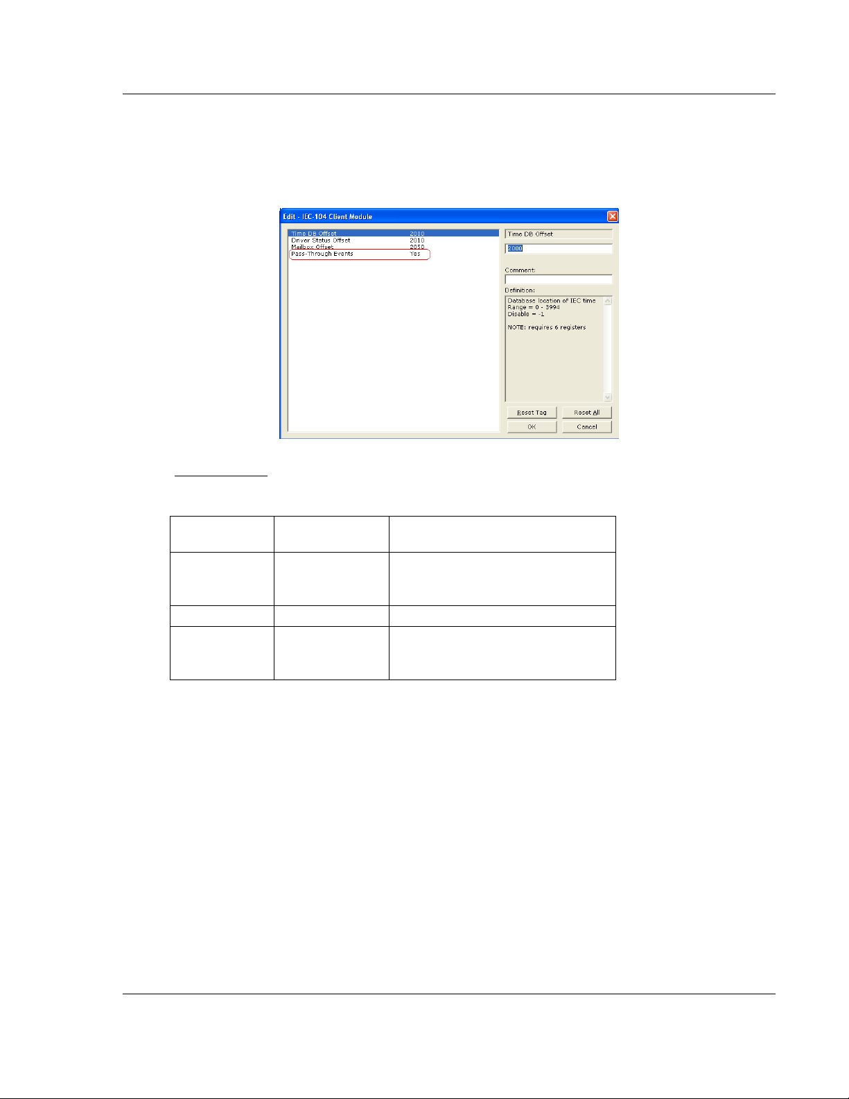
104C Version 3 ♦ ProLinx Gateway Mailbox Feature (x201-DFNT-104C)
IEC 60870-5-104 Client (Firmware v3.xx) Protocol Manual
4.3 Event Messages from Outstations Mailbox (9903)
Mailbox ±9903 is used to request event messages received by the client driver
from outstations. In order to use this feature you must enable Pass-Through
Events parameter in the IEC-104 Client Gateway section.
Mailbox Request
Word Offset in
Block
0 Mailbox ID This field contains the value of -9903 or
1 to 62 Not Used Not Used
63 Mailbox ID This field contains the value of -9903 or
Data Field(s) Description
9903 identifying the block type to the
module.
9903 identifying the block type to the
module.
ProSoft Technology, Inc. Page 73 of 139
August 4, 2011
Page 74

Mailbox Feature (x201-DFNT-104C) 104C Version 3 ♦ ProLinx Gateway
Protocol Manual IEC 60870-5-104 Client (Firmware v3.xx)
Mailbox Response
Word Offset in
Block
0 Mailbox ID This field contains the value of -9903
1 Event Count This field contains the number of
2 to 15 Event 1 Event message
16 to 29 Event 2 Event message
30 to 43 Event 3 Event message
44 to 57 Event 4 Event message
58 to 60 Spare Not Used
61 Event Count
62 Event Overflow This flag will be set if the event buffer
63 Mailbox ID This field contains the value of -9903
Data Field(s) Description
Remaining
or 9903 identifying the block type to
the module.
events present in the block. Values
of 0 to 4 are valid.
Number of events still present in the
event queue after removing these
events.
overflowed since last reported.
or 9903 identifying the block type to
the module.
The format of each 14 word data region in the block is as
follows:
Word Offset Definitions Description
0 Session Index This field contains the session index
used to define the controlled unit in
the module from which the event was
generated.
1 Sector Index This field contains the sector index
used to define the database within the
controlled unit from which the event
was generated.
2 COT This field contains the COT for the
event message received from the
IED. If the size of the COT is a single
byte, the originator address will
always be zero. The COT is in the
LSB and the originator address is in
the MSB.
Page 74 of 139 ProSoft Technology, Inc.
August 4, 2011
Page 75

104C Version 3 ♦ ProLinx Gateway Mailbox Feature (x201-DFNT-104C)
IEC 60870-5-104 Client (Firmware v3.xx) Protocol Manual
3 Reserved This field is reserved for future use
and is added here to keep the
structure double-word aligned for all
platforms.
4 to 5 Point Index This field contains the point index in
the remote device that generated the
event.
6 ASDU Type This field contains the ASDU type
code for the data contained in the
message.
7 Milliseconds and
Seconds
8 Minutes and Hours This field contains the minutes and
9 Month and Day This field contains the month and day
10 Year This field contains the year the event
11 Qualifier This field contains the point qualifier,
This word contains the seconds and
milliseconds when the event
occurred.
hours the event occurred.
of the month the event occurred.
occurred.
quality or sequence value as
described in the protocol
specification.
12 to 13 Value This field contains the a double word
value for the point associated with the
event message.
ProSoft Technology, Inc. Page 75 of 139
August 4, 2011
Page 76

Mailbox Feature (x201-DFNT-104C) 104C Version 3 ♦ ProLinx Gateway
Protocol Manual IEC 60870-5-104 Client (Firmware v3.xx)
4.4 General Gateway Status Mailbox (9250)
This mailbox requests the general gateway status
Mailbox Request
Word Offset in
Block
0 Mailbox ID This field contains the value of -9250 or
1 to 62 Not Used Not Used
63 Mailbox ID This field contains the value of -9250 or
Data Field(s) Description
Mailbox Response
Word Offset in
Block
0 Mailbox ID This field contains the value of -9250 or
Data Field(s) Description
9250 identifying the block type to the
module.
9250 identifying the block type to the
module.
9250 identifying the block type to the
module.
1 to 62 General status
data
63 Mailbox ID This field contains the value of -9250 or
General status data
9250 identifying the block type to the
module.
Page 76 of 139 ProSoft Technology, Inc.
August 4, 2011
Page 77

104C Version 3 ♦ ProLinx Gateway Mailbox Feature (x201-DFNT-104C)
IEC 60870-5-104 Client (Firmware v3.xx) Protocol Manual
The general status data has the following format:
OFFSET PARAMETER
0 Event Msg Cnt
1 Event Msg Overflow
2 Session Count
3 Current Cmd
4 Cmd Busy Flag
5 Cmd Count
6 Cmd Delay
7 Cmd Queue
8 Cmd Queue Count
9 to 10 Online Status
11 Spare
12 SNTP Valid
13 NTP Request
14 NTP Response
15 SNTP Computation
16 SNTP Set
17 NTP Timeout
ProSoft Technology, Inc. Page 77 of 139
August 4, 2011
Page 78

Mailbox Feature (x201-DFNT-104C) 104C Version 3 ♦ ProLinx Gateway
Protocol Manual IEC 60870-5-104 Client (Firmware v3.xx)
4.5 Client X Status Data Mailbox (9251)
This mailbox allows the Ethernet/IP remote device to request a 104 Client status
data from the module.
Mailbox Request
Word Offset in
Block
0 Mailbox ID This field contains the value of -9251 or
1 to 62 Client ID Client number (0-3)
2 to 62 Not Used Not Used
63 Mailbox ID This field contains the value of -9251 or
Data Field(s) Description
9251 identifying the block type to the
module.
9251 identifying the block type to the
module.
Mailbox Response
Word Offset in
Block
0 Mailbox ID This field contains the value of -9251 or
1 to 62 Client X status
63 Mailbox ID This field contains the value of -9251 or
Data Field(s) Description
data
9251 identifying the block type to the
module.
General status data
9251 identifying the block type to the
module.
Page 78 of 139 ProSoft Technology, Inc.
August 4, 2011
Page 79

104C Version 3 ♦ ProLinx Gateway Mailbox Feature (x201-DFNT-104C)
IEC 60870-5-104 Client (Firmware v3.xx) Protocol Manual
Mailbox 9251 – Client X Status Area
OFFSET PARAMETER DESCRIPTION
0 Active Active status of client
0 = not active
1 = waiting on StartDT con
2 = Online (StartDT con received)
1 State State of Client Socket:
-255 = Idle until processor in run
-1 = Ready for socket open
0 = Waiting for socket establish
1 = Read and write data to socket (process data)
70 = Sending StartDT act
80 = Sending StopDT act
100 = End program/close socket
1000 = Close socket (start 2-second timeout)
1001 = Wait for close & abort if timeout
2000 = ARP request/response
2001 = Open Socket
2 Open Count Number of times socket open attempted
3 Close Count Number of times socket closed
4 Connect Count Number of times socket established
5-14 Host IP ASCII string of remote server IP address (10 words)
15 t0 Timeouts Number of t0 timeouts
16 t1 Timeouts Number of t1 timeouts
17 t2 Timeouts Number of t2 timeouts
18 t3 Timeouts Number of t3 timeouts
19 Sequence Errors Number of sequence errors
20 Bad Address
Errors
21 Length Errors Number of length errors
22 Rx Frame Count Number of frames received on socket
23 Tx Frame Count Number of frames transmitted on socket
24 Cmd Requests Number of commands issued from command list and queue
25 Cmd Responses Number of responses to commands issued from command list and
26 Cmd Error Count Number of errors recognized when issued from command list or
27 Requests Number of requests from command driver
28 Responses Number of messages received by command driver
29 Errors Sent Number of errors sent by command driver (not used)
30 Errors Received Number of errors received by command driver
31 Configuration
Error
32 Current Error Current error recognized
33 Last Error Last error recognized
Number of bad address errors
queue.
queue
Configuration error word for client
ProSoft Technology, Inc. Page 79 of 139
August 4, 2011
Page 80

Mailbox Feature (x201-DFNT-104C) 104C Version 3 ♦ ProLinx Gateway
Protocol Manual IEC 60870-5-104 Client (Firmware v3.xx)
34 Send Number Send sequence number
35 Rec Number Received sequence number
36 Ack Number Last acknowledged sequence number
37 Queue Max Maximum number of queue (k)
38 Queue Threshold Queue threshold before S-Frame sent (w)
39 Rec Packets Number of I-frames received but not acknowledged
40 Queue Now Number of messages in queue
41 Queue First First index of message in queue
42 Queue Index Current index of message in queue
43 Spare Reserved for future use
Page 80 of 139 ProSoft Technology, Inc.
August 4, 2011
Page 81

104C Version 3 ♦ ProLinx Gateway Mailbox Feature (x201-DFNT-104C)
IEC 60870-5-104 Client (Firmware v3.xx) Protocol Manual
4.6 Command List Error Data Mailbox (9950)
Mailbox ±9950 identification code is used to request the Command List Error
Table from the module. The format for the block is shown below:
Mailbox Request
Word
Offset in
Block
0 Mailbox ID This field contains the value of -9950 or 9950
1 Number of
2 Start Index of First
Data Field(s) Description
Commands to
report
Command
identifying the block type to the module.
This field contains the number of commands to
report in the response message. The value has
a range of 1 to 60.
This parameter sets the index in the command
list where to start. The first command in the list
has a value of 0. The last index in the list has a
value of MaxCommands - 1.
3 to 62 Spare Not Used
63 Mailbox ID This field contains the value of -9950 or 9950
identifying the block type to the module.
ProSoft Technology, Inc. Page 81 of 139
August 4, 2011
Page 82

Mailbox Feature (x201-DFNT-104C) 104C Version 3 ♦ ProLinx Gateway
Protocol Manual IEC 60870-5-104 Client (Firmware v3.xx)
Mailbox Response
Word
Offset in
Block
0 Mailbox ID This field contains the value of -9950 or 9950
1 Number of
2 Start Index of First
3 to 62 Command List
Data Field(s) Description
Commands
reported
Command
Errors
identifying the block type to the module.
This field contains the number of commands
contained in the block that need to be
processed by the PLC. This field will have a
value of 1 to 60.
This field contains the index in the command list
for the first value in the file. This field will have a
value of 0 to MaxCommands-1.
Each word of this area contains the last error
value recorded for the command. The
command index of the first value (offset 4) is
specified in word 3 of the block. The number of
valid command errors in the block is set in word
2 of the block. Refer to the command error list
to interpret the error codes reported.
63 Mailbox ID This field contains the value of -9950 or 9950
identifying the block type to the module.
Page 82 of 139 ProSoft Technology, Inc.
August 4, 2011
Page 83

104C Version 3 ♦ ProLinx Gateway Mailbox Feature (x201-DFNT-104C)
IEC 60870-5-104 Client (Firmware v3.xx) Protocol Manual
4.7 Get Gateway Time Mailbox (9970)
Mailbox ±9970 identification code is used to request the IEC 104 client driver
date and time.
Mailbox Request
Word Offset in
Block
0 Mailbox ID This field contains the value of -9970 or 9970
1 to 62 Not Used Not Used
63 Mailbox ID This field contains the value of -9970 or 9970
Response to a block 9970 request -- The module will respond to a valid block 9970
request with a block containing the requested date and time. The format for the block
is shown below:
Data Field(s) Description
identifying the block type to the module.
identifying the block type to the module.
ProSoft Technology, Inc. Page 83 of 139
August 4, 2011
Page 84

Mailbox Feature (x201-DFNT-104C) 104C Version 3 ♦ ProLinx Gateway
Protocol Manual IEC 60870-5-104 Client (Firmware v3.xx)
Mailbox Response
Word Offset in
Block
0 Mailbox ID This field contains the value of -9970 or 9970
1 Year This field contains the four-digit year to be used
2 Month This field contains the month value for the new
3 Day This field contains the day value for the new time.
4 Hour This field contains the hour value for the new time.
5 Minute This field contains the minute value for the new
6 Seconds This field contains the second value for the new
7 Milliseconds This field contains the millisecond value for the new
Data Field(s) Description
identifying the block type to the module.
with the new time value.
time. Valid entry for this field is in the range of 1 to
12.
Valid entry for this field is in the range of 1 to 31.
Valid entry for this field is in the range of 0 to 23.
time. Valid entry for this field is in the range of 0 to
59.
time. Valid entry for this field is in the range of 0 to
59.
time. Valid entry for this field is in the range of 0 to
999.
8 to 62 Not Used Not Used
63 Mailbox ID This field contains the value of -9970 or 9970
identifying the block type to the module.
Page 84 of 139 ProSoft Technology, Inc.
August 4, 2011
Page 85

104C Version 3 ♦ ProLinx Gateway Mailbox Feature (x201-DFNT-104C)
IEC 60870-5-104 Client (Firmware v3.xx) Protocol Manual
4.8 Set Gateway Time Mailbox (9971)
Mailbox identification code ±9971 is used to pass the date and time to the
module. The date and time provided will be used to set the 104 client drivers
clock.
Mailbox Request
Word Offset
in Block
0 Mailbox ID This field contains the block identification code of -9971 or 9971
1 Year This field contains the four-digit year to be used with the new
2 Month This field contains the month value for the new time. Valid entry
3 Day This field contains the day value for the new time. Valid entry for
4 Hour This field contains the hour value for the new time. Valid entry
5 Minute This field contains the minute value for the new time. Valid entry
6 Seconds This field contains the second value for the new time. Valid entry
7 Milliseconds This field contains the millisecond value for the new time. Valid
8 to 62 Not Used Not Used
63 Mailbox ID This field contains the block identification code of -9971 or 9971
Data Field(s) Description
for the block.
time value.
for this field is in the range of 1 to 12.
this field is in the range of 1 to 31.
for this field is in the range of 0 to 23.
for this field is in the range of 0 to 59.
for this field is in the range of 0 to 59.
entry for this field is in the range of 0 to 999.
for the block.
ProSoft Technology, Inc. Page 85 of 139
August 4, 2011
Page 86

Mailbox Feature (x201-DFNT-104C) 104C Version 3 ♦ ProLinx Gateway
Protocol Manual IEC 60870-5-104 Client (Firmware v3.xx)
Mailbox Response
Word Offset
in Block
0 Mailbox ID This field contains the block identification code of -9971 or 9971
1 Year This field contains the four-digit year to be used with the new
2 Month This field contains the month value for the new time. Valid entry
3 Day This field contains the day value for the new time. Valid entry for
4 Hour This field contains the hour value for the new time. Valid entry
5 Minute This field contains the minute value for the new time. Valid entry
6 Seconds This field contains the second value for the new time. Valid entry
7 Milliseconds This field contains the millisecond value for the new time. Valid
8 to 62 Not Used Not Used
63 Mailbox ID This field contains the block identification code of -9971 or 9971
Data Field(s) Description
for the block.
time value.
for this field is in the range of 1 to 12.
this field is in the range of 1 to 31.
for this field is in the range of 0 to 23.
for this field is in the range of 0 to 59.
for this field is in the range of 0 to 59.
entry for this field is in the range of 0 to 999.
for the block.
Page 86 of 139 ProSoft Technology, Inc.
August 4, 2011
Page 87

104C Version 3 ♦ ProLinx Gateway Mailbox Feature (x201-DFNT-104C)
IEC 60870-5-104 Client (Firmware v3.xx) Protocol Manual
4.9 Reset Status Data Mailbox (9997)
This mailbox requests the module to reset all status counters
Mailbox Request
Word Offset in
Block
0 Mailbox ID This field contains the value of -9997 or
1 Reset Module
2 Reset Client 1
3 Reset Client 2
4 Reset Client 3
5 Reset Client 4
1 to 62 Not Used Not Used
63 Mailbox ID This field contains the value of -9997 or
Data Field(s) Description
Status
Status
Status
Status
Status
9997 identifying the block type to the
module.
Set a value of 1 to reset the module
status
Set a value of 1 to reset client 1 status
Set a value of 1 to reset client 2 status
Set a value of 1 to reset client 3 status
Set a value of 1 to reset client 4 status
9997 identifying the block type to the
module.
Mailbox Response
Word Offset in
Block
0 Mailbox ID This field contains the value of -9997 or
1 to 62 Reserved Reserved
63 Mailbox ID This field contains the value of -9997 or
Data Field(s) Description
9997 identifying the block type to the
module.
9997 identifying the block type to the
module.
ProSoft Technology, Inc. Page 87 of 139
August 4, 2011
Page 88

Mailbox Feature (x201-DFNT-104C) 104C Version 3 ♦ ProLinx Gateway
Protocol Manual IEC 60870-5-104 Client (Firmware v3.xx)
4.10 Coldboot Mailbox (9998/9999)
This mailbox allows the remote device to request a coldboot operation from the
module. The request block should contain block ID 9999. Once the module builds
the mailbox response block ID 9999 then the remote device should write a block
ID 9998 to confirm the acknowledgment.
Coldboot request:
Mailbox Request
Word Offset in
Block
0 Mailbox ID This field contains the value of -9999 or
1 to 62 Not Used Not Used
63 Mailbox ID This field contains the value of -9999 or
Data Field(s) Description
9999 identifying the block type to the
module.
9999 identifying the block type to the
module.
Mailbox Response
Word Offset in
Block
0 Mailbox ID This field contains the value of -9999 or
1 to 62 Reserved Reserved
63 Mailbox ID This field contains the value of -9999 or
Data Field(s) Description
9999 identifying the block type to the
module.
9999 identifying the block type to the
module.
Page 88 of 139 ProSoft Technology, Inc.
August 4, 2011
Page 89

104C Version 3 ♦ ProLinx Gateway Mailbox Feature (x201-DFNT-104C)
IEC 60870-5-104 Client (Firmware v3.xx) Protocol Manual
Coldboot confirmation:
Mailbox Request
Word Offset in
Block
0 Mailbox ID This field contains the value of -9998 or
1 to 62 Not Used Not Used
63 Mailbox ID This field contains the value of -9998 or
Data Field(s) Description
9998 identifying the block type to the
module.
9998 identifying the block type to the
module.
Mailbox Response
Word Offset in
Block
0 Mailbox ID This field contains the value of -9998 or
1 to 62 Reserved Reserved
63 Mailbox ID This field contains the value of -9998 or
Data Field(s) Description
9998 identifying the block type to the
module.
9998 identifying the block type to the
module.
ProSoft Technology, Inc. Page 89 of 139
August 4, 2011
Page 90

Mailbox Feature (x201-DFNT-104C) 104C Version 3 ♦ ProLinx Gateway
Protocol Manual IEC 60870-5-104 Client (Firmware v3.xx)
Page 90 of 139 ProSoft Technology, Inc.
August 4, 2011
Page 91

104C Version 3 ♦ ProLinx Gateway Diagnostics and Troubleshooting
IEC 60870-5-104 Client (Firmware v3.xx) Protocol Manual
5 Diagnostics and Troubleshooting
In This Chapter
Ethernet LED Indicators ........................................................................ 92
Using ProSoft Configuration Builder (PCB) for Diagnostics................... 93
There are two ways to troubleshoot ProLinx gateways:
Using the LEDs located on the front of the gateway
Using the Debug port, which provides a view into the gateway's internal
database.
ProSoft Technology, Inc. Page 91 of 139
August 4, 2011
Page 92

Diagnostics and Troubleshooting 104C Version 3 ♦ ProLinx Gateway
Protocol Manual IEC 60870-5-104 Client (Firmware v3.xx)
5.1 Ethernet LED Indicators
LED State Description
Data OFF No activity on the Ethernet port.
GREEN Flash The Ethernet port is actively transmitting or receiving data.
Link OFF No physical network connection is detected. No Ethernet
GREEN Solid Physical network connection detected. This LED must be ON
communication is possible. Check wiring and cables.
solid for Ethernet communication to be possible.
Page 92 of 139 ProSoft Technology, Inc.
August 4, 2011
Page 93

104C Version 3 ♦ ProLinx Gateway Diagnostics and Troubleshooting
IEC 60870-5-104 Client (Firmware v3.xx) Protocol Manual
5.2 Using ProSoft Configuration Builder (PCB) for Diagnostics
The Configuration and Debug menu for this gateway is arranged as a tree
structure, with the Main menu at the top of the tree, and one or more sub-menus
for each menu command. The first menu you see when you connect to the
gateway is the Main menu.
Because this is a text-based menu system, you enter commands by typing the
[command letter] from your computer keyboard in the Diagnostic window in
ProSoft Configuration Builder (PCB). The gateway does not respond to mouse
movements or clicks. The command executes as soon as you press the
[
COMMAND LETTER
[
COMMAND LETTER
] — you do not need to press [E
NTER].
When you type a
], a new screen will be displayed in your terminal application.
5.2.1 Required Hardware
You can connect directly from your PC’s serial port to the serial port on the
gateway to view configuration information, perform maintenance, and send or
receive configuration files.
ProSoft Technology recommends the following minimum hardware to connect
your PC to the gateway:
80486 based processor (Pentium preferred)
1 megabyte of memory
At least one UART hardware-based serial communications port available.
USB-based virtual UART systems (USB to serial port adapters) often do not
function reliably, especially during binary file transfers, such as when
uploading/downloading configuration files or gateway firmware upgrades.
5.2.2 Using the Diagnostic Window in ProSoft Configuration Builder
Tip: You can have a ProSoft Configuration Builder Diagnostics window open for more than one
module at a time.
ProSoft Technology, Inc. Page 93 of 139
August 4, 2011
Page 94
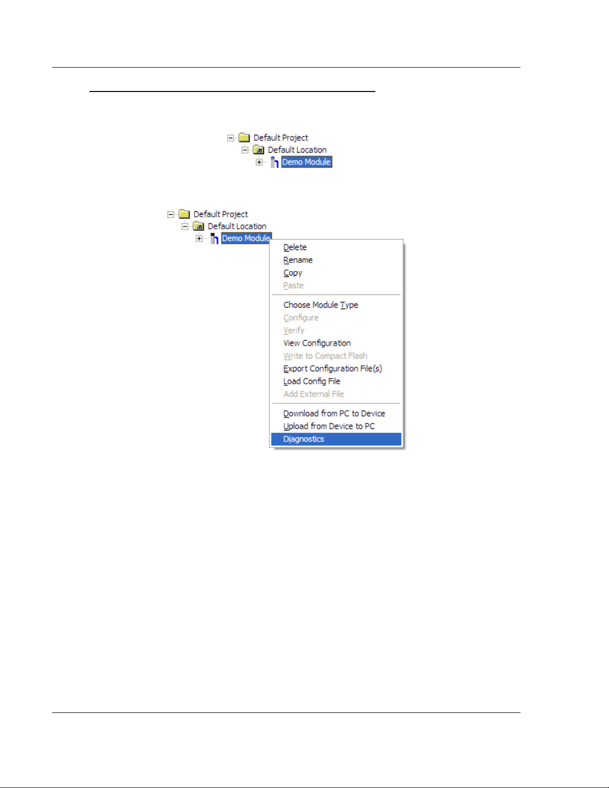
Diagnostics and Troubleshooting 104C Version 3 ♦ ProLinx Gateway
Protocol Manual IEC 60870-5-104 Client (Firmware v3.xx)
To connect to the gateway’s Configuration/Debug serial port
1 Start PCB, and then select the gateway to test. Click the right mouse button
to open a shortcut menu.
2 On the shortcut menu, choose D
IAGNOSTICS
.
This action opens the Diagnostics dialog box.
Page 94 of 139 ProSoft Technology, Inc.
August 4, 2011
Page 95

104C Version 3 ♦ ProLinx Gateway Diagnostics and Troubleshooting
IEC 60870-5-104 Client (Firmware v3.xx) Protocol Manual
3 Press [?] to open the Main menu.
If there is no response from the gateway, follow these steps:
1 Click to configure the connection. On the Connection Setup dialog box, select
a valid com port or other connection type supported by the gateway.
2 Verify that the null modem cable is connected properly between your
computer’s serial port and the gateway. A regular serial cable will not work.
3 On computers with more than one serial port, verify that your communication
program is connected to the same port that is connected to the gateway.
If you are still not able to establish a connection, contact ProSoft Technology for
assistance.
ProSoft Technology, Inc. Page 95 of 139
August 4, 2011
Page 96
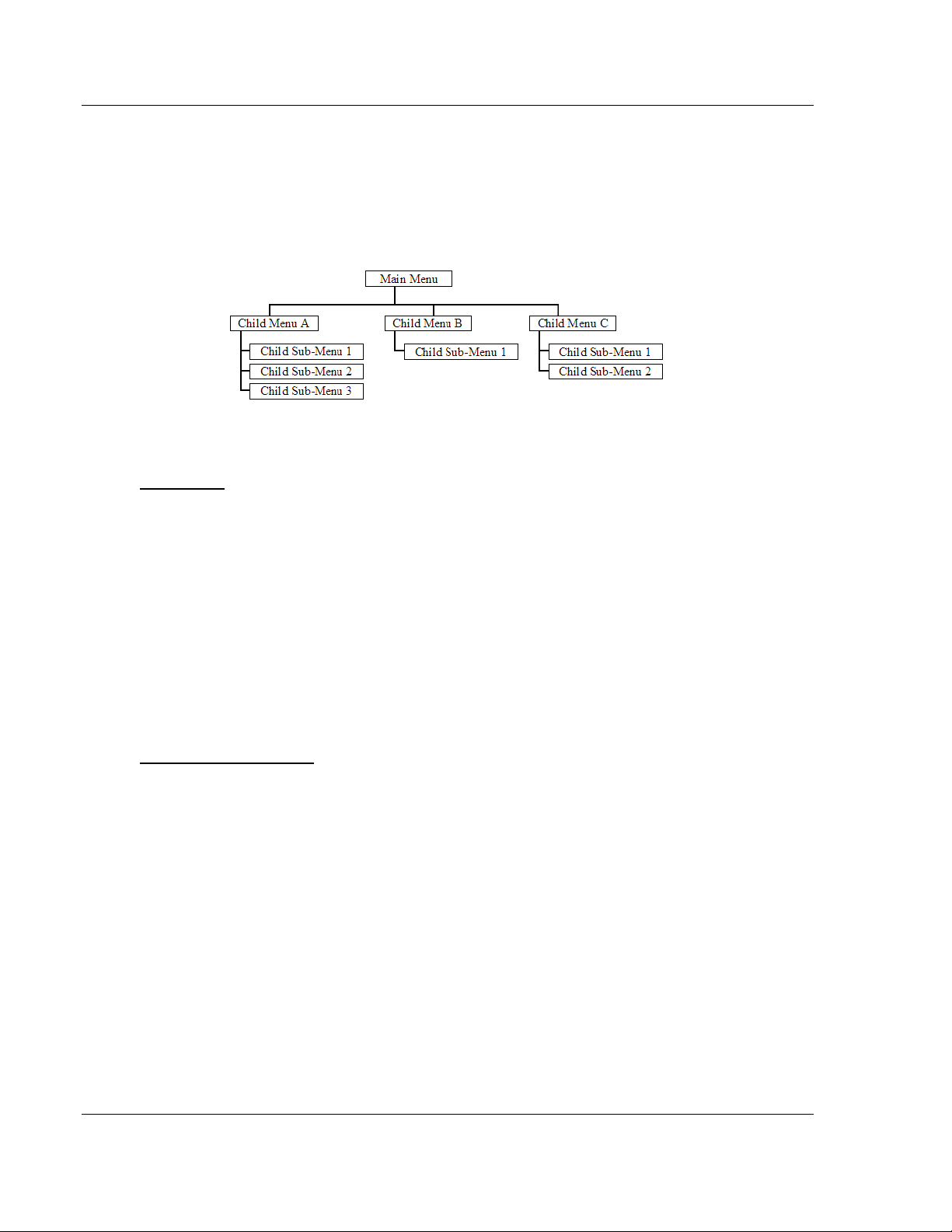
Diagnostics and Troubleshooting 104C Version 3 ♦ ProLinx Gateway
Protocol Manual IEC 60870-5-104 Client (Firmware v3.xx)
5.2.3 Navigation
All of the submenus for this gateway contain commands to redisplay the menu or
return to the previous menu. You can always return from a submenu to the next
higher menu by pressing [M] on your keyboard.
The organization of the menu structure is represented in simplified form in the
following illustration:
The remainder of this section shows the menus available for this gateway, and
briefly discusses the commands available to you.
Keystrokes
The keyboard commands on these menus are usually not case sensitive. You
can enter most commands in lowercase or uppercase letters.
The menus use a few special characters (?, -, +, @) that must be entered exactly
as shown. Some of these characters will require you to use the SHIFT, CTRL, or
ALT keys to enter them correctly. For example, on US English keyboards, enter
the ? command as SHIFT and /.
Also, take care to distinguish the different uses for uppercase letter "eye" (I),
lowercase letter "el" (L), and the number one (1). Likewise, uppercase letter "oh"
(O) and the number zero (0) are not interchangeable. Although these characters
look alike on the screen, they perform different actions on the gateway and may
not be used interchangeably.
Redisplaying the Menu
Press [?] to display the current menu. Use this command when you are looking
at a screen of data, and want to view the menu choices available to you.
Page 96 of 139 ProSoft Technology, Inc.
August 4, 2011
Page 97
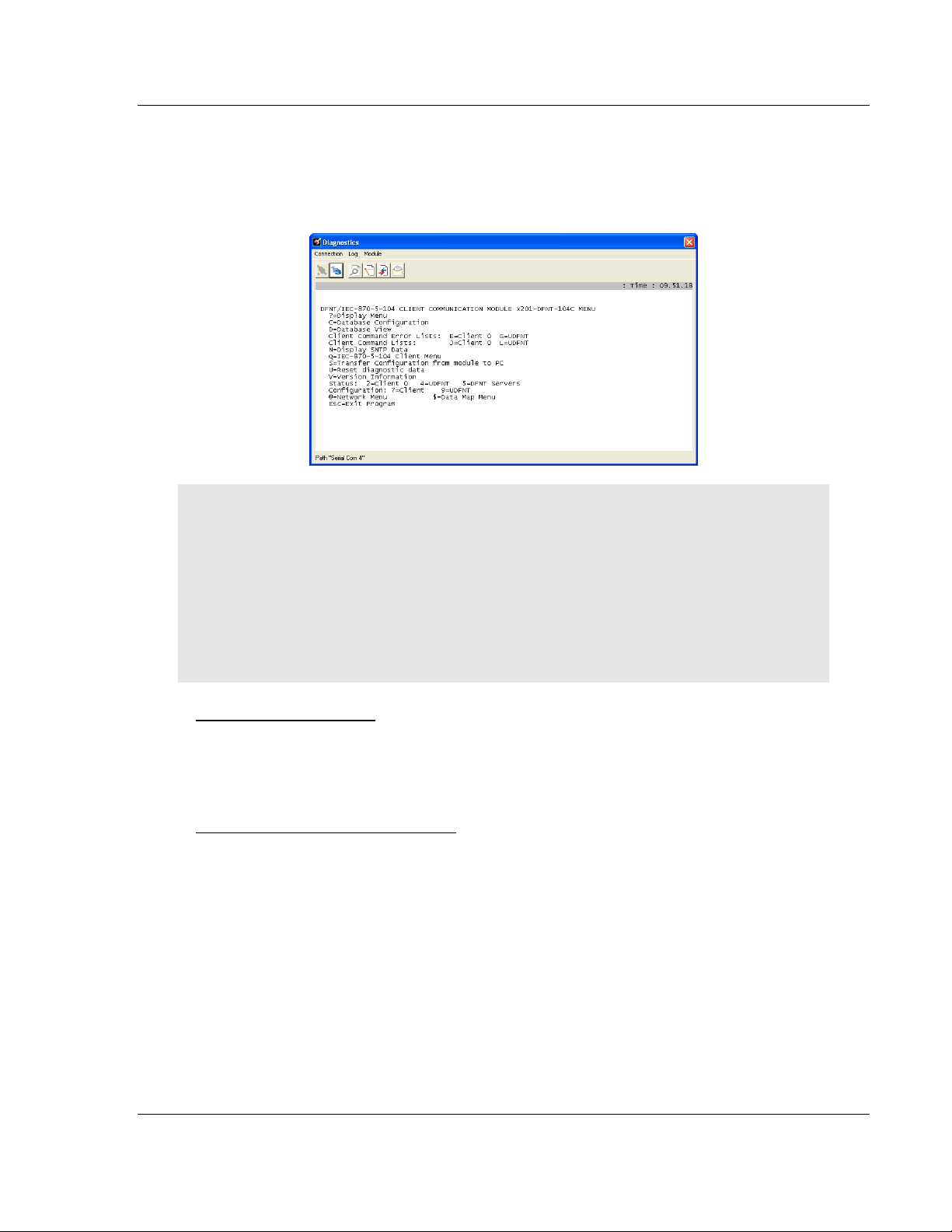
104C Version 3 ♦ ProLinx Gateway Diagnostics and Troubleshooting
IEC 60870-5-104 Client (Firmware v3.xx) Protocol Manual
5.2.4 Main Menu
When you first connect to the module from your computer, your terminal screen
will be blank. To activate the Main menu, press the [?] key on your computer’s
keyboard. If the module is connected properly, the following menu will appear.
Caution: Some of the commands available to you from this menu are designed for advanced
debugging and system testing only, and can cause the gateway to stop communicating with the
processor or with other devices, resulting in potential data loss or other communication failures.
Use these commands only if you fully understand their potential effects, or if you are specifically
directed to do so by ProSoft Technology Technical Support Engineers.
There may be some special command keys that are not listed on the menu but that may activate
additional diagnostic or debugging features. If you need these functions, you will be advised how to
use them by Technical Support. Please be careful when pressing keys so that you do not
accidentally execute an unwanted command.
Database Configuration
Press [C] to view the Module Configuration screen.
Use this command to display the current configuration and statistics for the
gateway.
Opening the Database View Menu
Press [D] to open the Database View menu.
Use this menu command to view the current contents of the gateway’s database.
For more information about this submenu, see Database View Menu (page 99).
ProSoft Technology, Inc. Page 97 of 139
August 4, 2011
Page 98
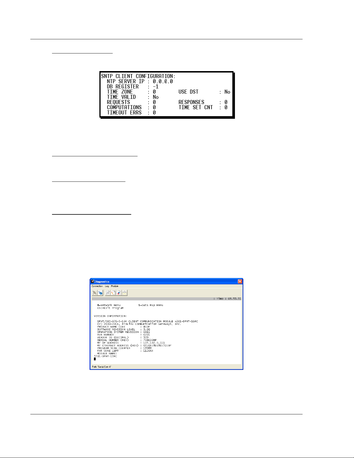
Diagnostics and Troubleshooting 104C Version 3 ♦ ProLinx Gateway
Protocol Manual IEC 60870-5-104 Client (Firmware v3.xx)
Viewing SNTP Status
Press [N] to view configuration information about the SNTP Client.
For more information on configuring and using this function, see SNTP Client
(page 17).
Sending the Configuration File
Press [S] to upload (send) a configuration file from the gateway to your PC.
Resetting Diagnostic Data
Press [U] to reset the status counters for the Client and/or server(s) in the
gateway.
Viewing Version Information
Press [V] to view version information for the gateway.
Use this command to view the current version of the software for the gateway, as
well as other important values. You may be asked to provide this information
when calling for technical support on the product.
Values at the bottom of the display are important in determining gateway
operation. The Program Scan Counter value is incremented each time a
gateway’s program cycle is complete.
Page 98 of 139 ProSoft Technology, Inc.
August 4, 2011
Page 99
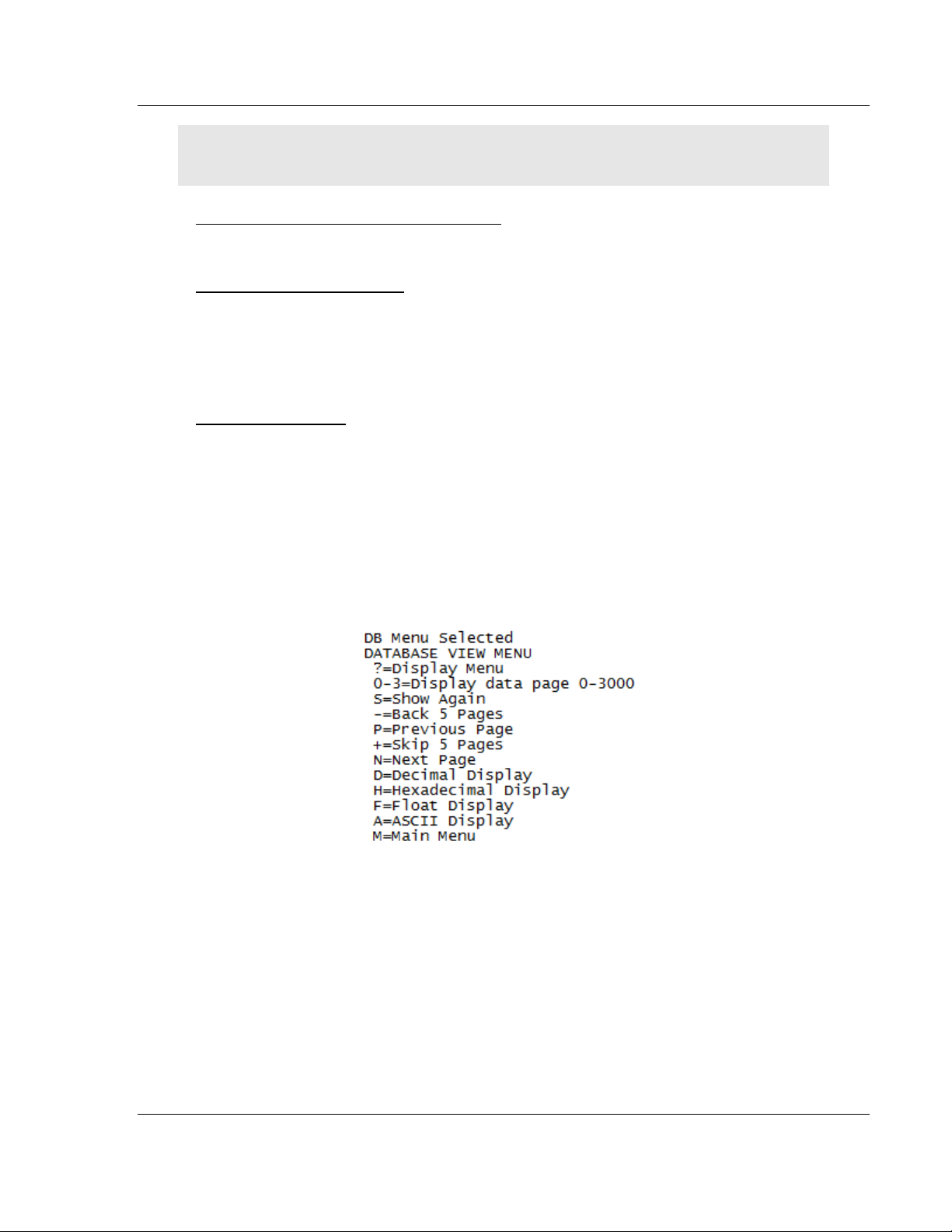
104C Version 3 ♦ ProLinx Gateway Diagnostics and Troubleshooting
IEC 60870-5-104 Client (Firmware v3.xx) Protocol Manual
Tip: Repeat this command at one-second intervals to determine the frequency of program
execution.
Opening the IEC 870-5-104 Client Menu
Press [ Q ] to view all data associated with the IEC 60870-5-104 Client driver.
Opening the Network Menu
Press [@] to open the Network menu.
The Network menu allows you to send, receive and view the WATTCP.CFG file
that contains the IP, gateway and other network specification information. For
more information about this submenu, see Network Menu (page 104).
Exiting the Program
Press [ESC] to restart the gateway and force all drivers to be loaded. The
gateway will use the configuration stored in the gateway's flash memory to
configure the gateway.
5.2.5 Database View Menu
Press [D] from the Main menu to open the Database View menu. Use this menu
command to view the current contents of the gateway database. Press [?] to
view a list of commands available on this menu.
ProSoft Technology, Inc. Page 99 of 139
August 4, 2011
Page 100
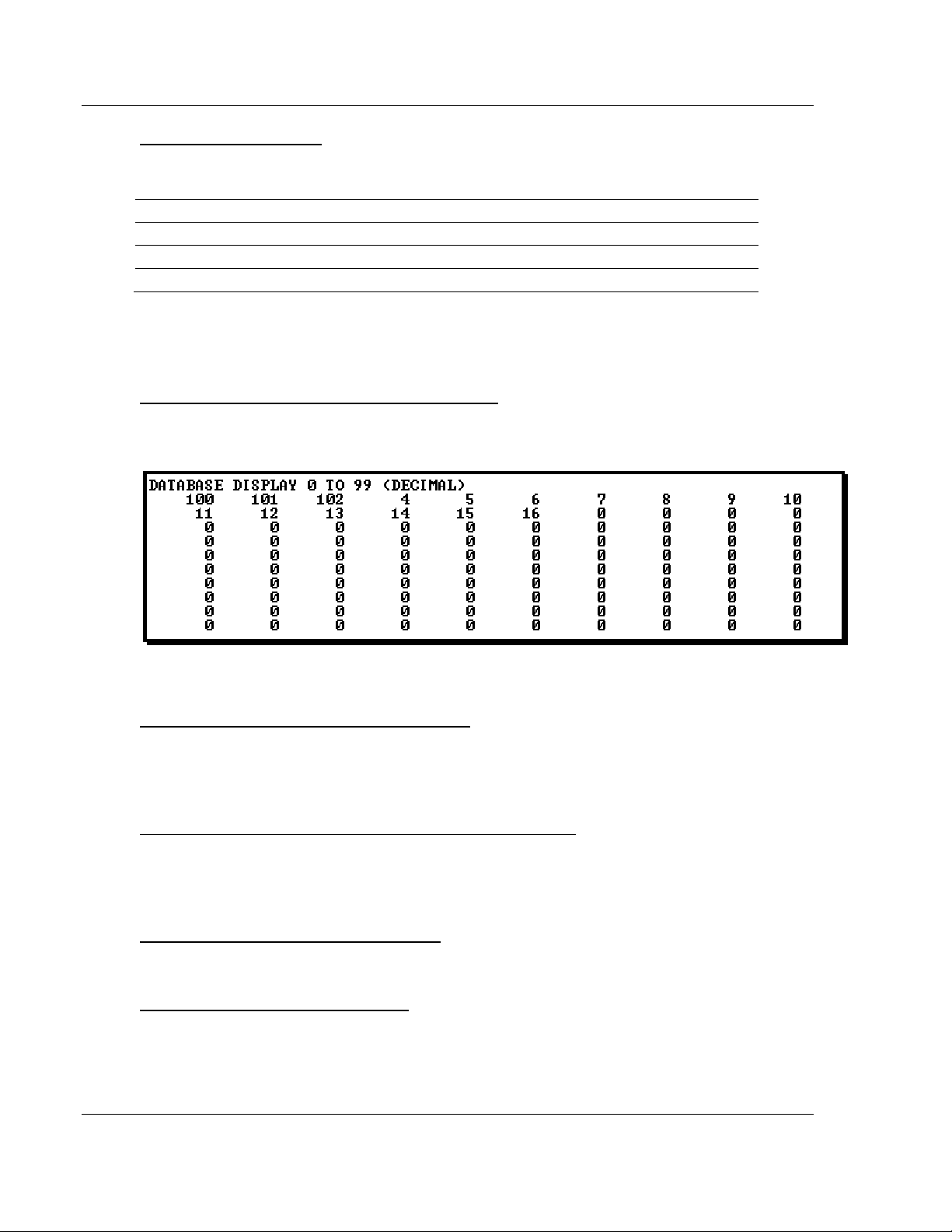
Diagnostics and Troubleshooting 104C Version 3 ♦ ProLinx Gateway
Protocol Manual IEC 60870-5-104 Client (Firmware v3.xx)
Viewing Register Pages
To view sets of register pages, use the keys described below:
Command Description
[0]
[1]
[2]
Display registers 0 to 99
Display registers 1000 to 1099
Display registers 2000 to 2099
And so on. The total number of register pages available to view depends on your
gateway’s configuration.
Displaying the Current Page of Registers Again
Press [S] from the Database View menu to show the current page of registers
again.
This screen displays the current page of 100 registers in the database.
Moving Back Through 5 Pages of Registers
Press [-] from the Database View menu to skip five pages back in the database
to see the 100 registers of data starting 500 registers before the currently
displayed page.
Moving Forward (Skipping) Through 5 Pages of Registers
Press [+] from the Database View menu to skip five pages ahead in the database
to see the 100 registers of data starting 500 registers after the currently displayed
page.
Viewing the Previous Page of Registers
Press [P] from the Database View menu to display the previous page of data.
Viewing the Next Page of Registers
Press [N] from the Database View menu to display the next page of data.
Page 100 of 139 ProSoft Technology, Inc.
August 4, 2011
 Loading...