

Page 1

Web Server
September 28, 2005
Reference Manual
Page 2

Please Read This Notice
The use and configuration of this software requires a reasonable working knowledge of the
involved protocols and the application in which they are to be used. For this reason, it is important
that those responsible for implementation satisfy themselves that the combination will meet the
needs of the application without exposing personnel or equipment to unsafe or inappropriate
working conditions.
This manual is provided to assist the user. Every attempt has been made to assure that the
information provided is accurate and a true reflection of the product's functionality. In order to
assure a complete understanding of the operation of the product, the user should read all
applicable ProSoft documentation on the operation of the module and protocol driver.
Under no conditions will ProSoft Technology, Inc. be responsible or liable for indirect or
consequential damages resulting from the use or application of the product. Reproduction of the
contents of this manual, in whole or in part, without written permission from ProSoft Technology,
Inc. is prohibited.
Information in this manual is subject to change without notice and does not represent a
commitment on the part of ProSoft Technology, Inc. Improvements and/or changes in this manual
or the product may be made at any time. These changes will be made periodically to correct
technical inaccuracies or typographical errors.
Your Feedback Please
We always want you to feel that you made the right decision to use our products. If you have
suggestions, comments, compliments or complaints about the product, documentation or support,
please write or call us.
ProSoft Technology, Inc.
1675 Chester Avenue, Second Floor
Bakersfield, CA 93301
(661) 716-5100
(661) 716-5101 (Fax)
http://www.prosoft-technology.com
Copyright © ProSoft Technology, Inc. 2000 - 2005. All Rights Reserved.
Web Server Reference Manual
September 28, 2005
Page 3

Contents Web Server ♦
Contents
PLEASE READ THIS NOTICE...........................................................................................................2
Your Feedback Please ..................................................................................................................2
1 INTRODUCTION .........................................................................................................................5
2 FUNCTIONAL SPECIFICATIONS ..............................................................................................7
2.1 Ethernet Port Specifications ........................................................................................7
3 ETHERNET PORT CONFIGURATION: WATTCP.CFG.............................................................9
3.1 Overview and Purpose of wattcp.cfg file ....................................................................9
3.2 Default wattcp.cfg File ..................................................................................................9
3.3 Editing the CFG file.....................................................................................................10
3.3.1 Comment Records and Editing Hints...........................................................................10
3.4 Section Descriptions...................................................................................................10
3.5 Downloading wattcp.cfg file to the ProLinx Unit......................................................10
3.5.1 Hardware Setup to Download......................................................................................11
4 CFG FILE: [E-MAIL] SECTION ................................................................................................13
4.1 Creating Custom E-Mail Reports ...............................................................................14
4.2 Example E-mail Report File........................................................................................14
5 WEB PAGE CONSTRUCTION .................................................................................................17
5.1 HTML Document Structure.........................................................................................17
5.2 The Home Page............................................................................................................18
5.3 Adding Hyperlinks to Pages.......................................................................................19
5.4 Adding Images to Pages.............................................................................................19
5.5 Using Frames and Tables to Lay Out Pages ............................................................20
5.6 Adding Forms to Pages..............................................................................................21
5.7 Data Display.................................................................................................................25
5.7.1 <--MOD_NAME --> ......................................................................................................25
5.7.2 <--MYIP --> ..................................................................................................................25
5.7.3 <--DATE 0 --> ..............................................................................................................25
ProSoft Technology, Inc. Page 3 of 35
September 28, 2005
Page 4

Web Server ♦ Contents
5.7.4 <--DATE 1 --> .............................................................................................................. 25
5.7.5 <--TIME --> .................................................................................................................. 26
5.7.6 <--DATA start,count,cols,fmt -->.................................................................................. 26
5.7.7 <--BTEXT start,on_text,off_text --> ............................................................................. 27
5.7.8 <--BIMAGE start,on_file,off_file,alignment --> ............................................................ 27
5.8 Automatically Refreshing a Page.............................................................................. 27
5.9 File_1.htm .................................................................................................................... 28
5.10 File_2.htm .................................................................................................................... 28
5.11 Index.htm..................................................................................................................... 28
5.12 File Naming Conventions........................................................................................... 29
5.13 Further Reading .......................................................................................................... 30
6 FTP SERVER............................................................................................................................ 31
6.1 Logging into the ProLinx unit.................................................................................... 32
7 ETHERNET LED INDICATORS ...............................................................................................33
INDEX...............................................................................................................................................35
Page 4 of 35 ProSoft Technology, Inc.
September 28, 2005
Page 5

Introduction Web Server
1 Introduction
This document contains a description of the facilities offered on the Web Server
available on all network-enabled ProLinx Communication Gateways, Inc.
modules. The server provides remote interfacing of the module with any Web
browser to user constructed HTML pages that are present on the module. The
steps in implementing this feature are as follows:
1 Set up the network parameters in the module's WATTCP.CFG file found in
the root directory.
2 Design your Web-page stack on paper and determine the database elements
required on each page.
3 Build a set of Web pages to interface with the virtual database of the module.
4 Test the Web pages built to be certain all links and image files are present.
5 Download all files required to the C:\ (root) directory on the module. You may
need to remove the existing set of files before downloading the new file set.
6 If the application program on the unit is not running, restart the module by
pressing the Reset Pushbutton.
7 Open the Web browser on your computer and connect to the home page of
the module. You can name the home page anything you want, but most home
pages are named INDEX.HTM. If you only supply the IP address as the URL
in your browser, the module will default to the INDEX.HTM page. Therefore, it
is recommended that the home page be named INDEX.HTM.
8 Test out your Web pages to be certain all links and image files are present.
9 Check all data entry fields on forms in the Web pages to be certain the data is
posted to the virtual database of the module.
If you do not have any familiarity with HTML, there are many good books and
software packages that can aid in your development. You should be able to start
with the Web pages provided by ProLinx Communication Gateways, Inc. and
customize them for your application. The best method is to start with simple
pages and advance to more complex pages after you understand the HTML
language.
ProSoft Technology, Inc. Page 5 of 35
September 28, 2005
Page 6

Web Server Introduction
Page 6 of 35 ProSoft Technology, Inc.
September 28, 2005
Page 7

Functional Specifications Web Server
2 Functional Specifications
In This Chapter
¾ Ethernet Port Specifications..................................................... 7
2.1 Ethernet Port Specifications
Physical Connection
Ethernet
Web Server
General
Web pages HTML file max size: 8 MB
Data Insertion Tags
POST Functionality
Type Specifications
E-Mail Client
General Module sends user defined e-mail reports to specified e-mail server.
Standard 10Base-T connector. Uses standard cable to connect to hub,
or crossover cable to connect directly to PC
The module contains a web server capable of delivering factory supplied
web pages and customer created web pages.
Remote control of module's database through Web pages
Support of Password security for data altering operations (POST
command)
Use standard web editing tools to create the web pages
Supports database access from bit level to float data types
Insert dynamic data from internal database registers
Special tags have been added to web server to support insertion of
register values from internal database into web pages. These include:
Module Name
Module IP Address
Data
Time
Data(w/ 'C' language formatting options)
Binary Triggered Text Message
Binary Triggered Images
Special names have been defined in the unit to permit database
alteration using Web pages and the FORM command.
E-mails are triggered based on user configured register/value
combinations
E-mail reports can be embedded with date/time and data values from
internal database
ProSoft Technology, Inc. Page 7 of 35
September 28, 2005
Page 8

Web Server Functional Specifications
Physical Connection
FTP Server
General Transfer/view HTML files
Transfer/view e-mail files
Supports one (1) client connection
FTP initiated Warmboot of module
FTP initiated Coldboot of module
Supported FTP
Functionality
HTML File Transfer
Directory Operations
File Viewing
File Removal
Page 8 of 35 ProSoft Technology, Inc.
September 28, 2005
Page 9

Ethernet Port Configuration: wattcp.cfg Web Server
3 Ethernet Port Configuration: wattcp.cfg
In This Chapter
¾ Overview and Purpose of wattcp.cfg file .................................. 9
¾ Default wattcp.cfg File.............................................................. 9
¾ Editing the CFG file ................................................................ 10
¾ Section Descriptions .............................................................. 10
¾ Downloading wattcp.cfg file to the ProLinx Unit ..................... 10
This section of the documentation describes the configuration data required by
the communication module for a TCP/IP network connection. It is important that
the module be configured accurately for reliable and correct operation.
3.1 Overview and Purpose of wattcp.cfg file
All configuration information for the module's Ethernet port is stored in a text file
with the name wattcp.cfg. The file contains the configuration for the IP address,
as well any network specific gateways, etc. configuration that must be known by
the TCP/IP driver.
A working example wattcp.cfg file is shipped with the module and should be used
as a starting point for configuration. Use any text editor you are familiar with to
edit the data in the file. When you have completed editing the file, download it to
the module using the FTP capability of the module (See FTP Section of this
manual for reference purposes).
3.2 Default wattcp.cfg File
# ProLinx Communication Gateways, Inc.
# Default private class 3 address
my_ip=192.168.0.100
# Default class 3 network mask
netmask=255.255.255.0
# The gateway I wish to use
gateway=192.168.0.1,192.168.0.0,255.255.255.0
Warning: If the field of my_ip does not exist, or if the wattcp.cfg file is
corrupted or does not exist, the module will not function.
ProSoft Technology, Inc. Page 9 of 35
September 28, 2005
Page 10

Web Server Ethernet Port Configuration: wattcp.cfg
3.3 Editing the CFG file
You can use any text editor, such as "Notepad" to edit the wattcp.cfg file. The
simplest method for getting started is to download the default file from the web or
from the module itself. Once on the PC, open the file in the text editor and alter
as required for your network and application.
3.3.1 Comment Records and Editing Hints
Any record that begins with the '#' or a ';' character is considered to be a
comment record. These records can be placed anywhere in the file. These lines
are ignored in the file and can be used to provide documentation within the
configuration file. Liberal use of comments within the file can ease the use and
interpretation of the data in the file.
3.4 Section Descriptions
Section
Heading
my_ip= This is the IP addresses assigned to the unit.
netmask= This is the network mask to be used for your particular network.
gateway=
Description
This is the IP address of the gateway for your network. If you do not supply
this, the default is used. So for example if using an IP address of
192.168.0.100 your gateway statement would default to:
gateway=192.168.0.1,192.168.0.0,255.255.255.0
or
gateway=default gateway, default network, default mask
Note: The subnet must be specified for class B subnets
3.5 Downloading wattcp.cfg file to the ProLinx Unit
After editing the configuration file, save it to the disk on the local PC, and then
execute the instructions in the following discussion to download the file to the
ProLinx unit.
Page 10 of 35 ProSoft Technology, Inc.
September 28, 2005
Page 11
Ethernet Port Configuration: wattcp.cfg Web Server
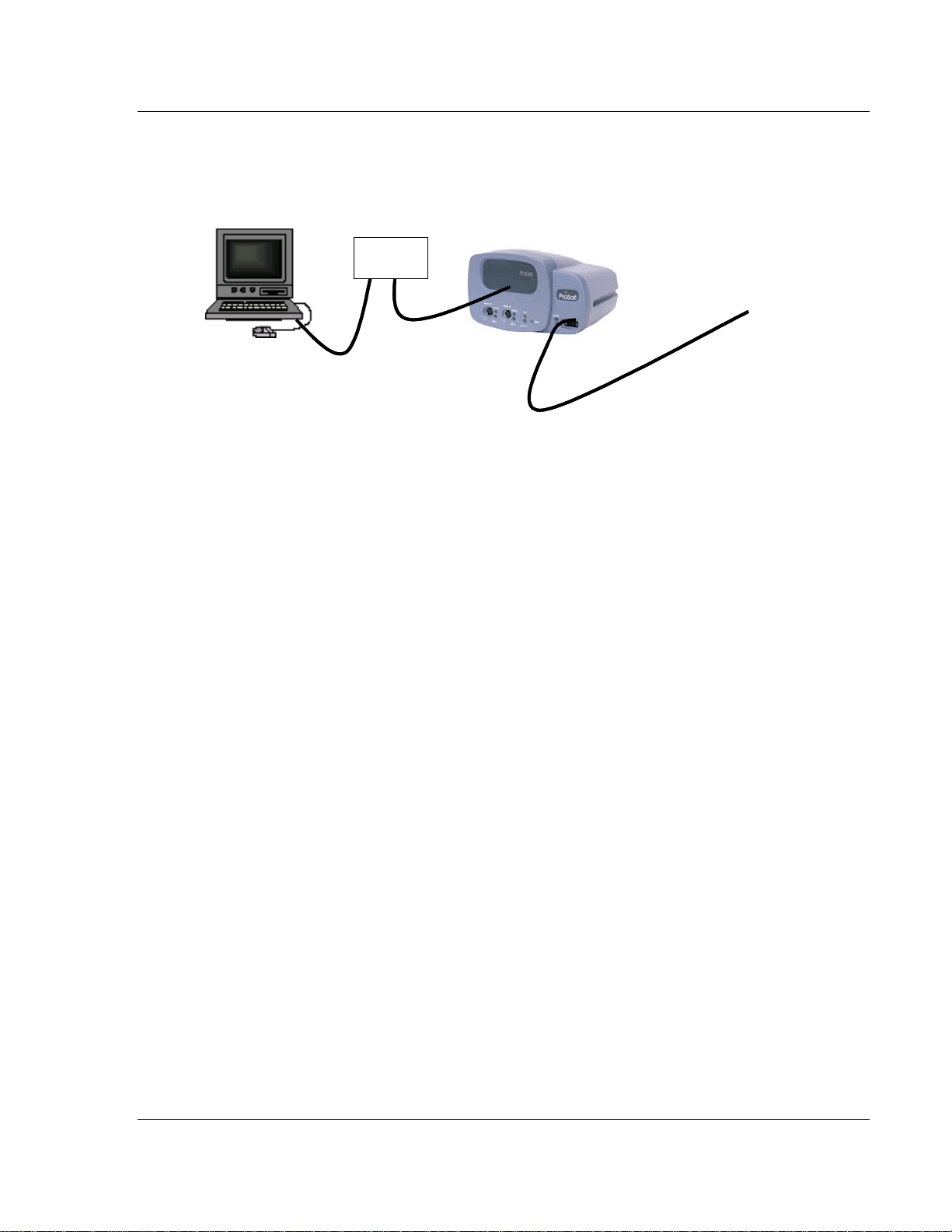
3.5.1 Hardware Setup to Download
Refer to the following illustration to connect your PC to the ProLinx module using
standard Ethernet cables through an Ethernet hub. This configuration will allow
you to transfer configuration files between the module and your PC.
Default IP = 192.168.0.100
Default IP = 192.168.0.100
Connect to 18-36 VDC
Connect to 18-36 VDC
Power supply
Power supply
PC running
PC running
FTP Client
FTP Client
Software such
Software such
As WS_FTP.
As WS_FTP.
Network
Network
HUB
HUB
ProSoft Technology, Inc. Page 11 of 35
September 28, 2005
Page 12

Web Server Ethernet Port Configuration: wattcp.cfg
Page 12 of 35 ProSoft Technology, Inc.
September 28, 2005
Page 13

CFG File: [E-MAIL] Section Web Server
4 CFG File: [E-MAIL] Section
In This Chapter
¾ Creating Custom E-Mail Reports............................................ 14
¾ Example E-mail Report File ................................................... 14
The [E-MAIL] section of the CFG file defines the network and file parameters to
be associated with each of the 20 potential e-mail messages that can be sent
from the module. The format of the section is different than the other sections of
the configuration file. Each e-mail definition is contained on a single line between
the labels START and END. These labels inform the program where the list
resides. The module's program will parse all data after the START label until it
reaches the END label or until 20 e-mail messages are defined.
The format of each definition in the list is the same with the content dependent on
the operation to perform. An example section from the CFG file is shown below:
[E-MAIL]
# DB Trigger Mail TO
# Reg Value Server IP Name E-Mail File Name
START
4000 1 192.168.0.5 user@aol.com stat
4000 2 192.168.0.5 user@aol.com commands
4000 3 192.168.0.5 user@aol.com errlist
4000 4 192.168.0.5 user@aol.com emailcfg
4000 5 192.168.0.5 user@aol.com example.rpt
END
Each parameter is discussed below:
Parameter Range Description
DB Reg 0 to 9999
Trigger
Value
Mail Server
IP
This parameter specifies the register in the virtual database in the
module to be associated with the Trigger Value parameter. The
register value can be controlled by Server devices based on data
acquired using the command list or from commands issued on the
network from a remote Client unit.
This parameter specifies the value in the database to trigger the email message. When the value entered for this parameter is first
recognized in the virtual database at the register specified in the DB
Reg parameter, the e-mail message will be generated. The value
must change in order for the value to be re-used. Most applications
will use a single register with different trigger values generating
different messages. The example displayed above uses this
technique.
This parameter specifies the IP address of the mail server to be
reached with the e-mail message. Refer to your network
administrator for this information.
ProSoft Technology, Inc. Page 13 of 35
September 28, 2005
Page 14

Web Server CFG File: [E-MAIL] Section
Parameter Range Description
To Name
E-Mail File
Name
This parameter must contain a valid user or e-mail account
information for your network. Groups of people can be designated to
receive an individual e-mail message by setting the appropriate
name in this field. Refer to your network administrator for a list of
accounts.
This parameter contains the fully qualified file and path name to the
file to be associated with the e-mail message. This file must reside
on the module's Flash ROM in order to be sent. Several e-mail files
are built into the module and do not need to be constructed by the
user. The reserved file names and a description of their content is
given below:
Stat -- This file contains the module's communication status data for
each network service and the Client port.
Emailcfg -- This file contains a listing of the e-mail configuration data.
All other file names entered must exist on the module.
4.1 Creating Custom E-Mail Reports
The ProLinx module is capable of supporting up to 20 user defined e-mail
reports. The following insertion tags can be used with e-mail messages:
Note: A space character must exist before the --> string or else the insertion
tag will be disregarded
<--DATE 0 --> insert the date in the format 02/07/2000.
<--DATE 1 --> insert the date in the format February 7, 2000.
<--TIME --> insert the time in the format 17:02:15.35
<--BTEXT 0,BIT_0_ON,BIT_0_OFF --> insert a text string based on the value of
a bit in the database.
<--DATA 0,1,1,%04d --> insert one or more data values from the database in the
user specified format.
Refer to the Web Page Definition section of the documentation on formatting files
with encapsulated data and insertion tags.
4.2 Example E-mail Report File
The following serves as an example of an e-mail report file. This file is available
on the ProLinx unit, and can be accessed via the FTP port.
TO : Production Engineers
FROM : 4201-WEB-DFM, ProSoft Technology, Inc. Module
SUBJECT: Production Report for Shipping Pumps
This is an example of the type of e-mail that can be sent from the module to
a remote site using the e-mail feature. The data contained in the report
displays several methods of displaying data in a report from the module's
Page 14 of 35 ProSoft Technology, Inc.
September 28, 2005
Page 15

CFG File: [E-MAIL] Section Web Server
database.
Register 0 = <--DATA 0,1,1,%d --> (this is the report number flag value)
DATE 0 = <--DATE 0 -->
DATE 1 = <--DATE 1 -->
TIME = <--TIME -->
BTEXT = <--BTEXT 0,BIT_0_ON,BIT_0_OFF --> (state of bit 0)
DATA = <--DATA 0,1,1,%04d -->
PUMP DATA:
On Time Suction Discharge Temp
(Hours) (PSIG) (PSIG) (F)
<--DATA 0,12,4,%12d -->
End of report.
ProSoft Technology, Inc. Page 15 of 35
September 28, 2005
Page 16

Web Server CFG File: [E-MAIL] Section
Page 16 of 35 ProSoft Technology, Inc.
September 28, 2005
Page 17

Web Page Construction Web Server
5 Web Page Construction
The WEB driver in the module provides the facility to generate Web pages to a
remote browser on the network using the http service port 80. Several Web
pages are built into the software and require no special handling. You can
construct custom Web pages to be generated by the program. These custom
pages can contain data from the virtual database, images (static and dynamic)
and text (static and dynamic). The following steps should be followed to use this
feature:
1 Use any standard Web page authoring tool or word processor that can
generate a standard HTML file for use with an http server.
2 Download these files to the C:\ directory on the module using the FTP server.
3 Test the download files using your Web browser.
The only limit on the number of Web pages that can be generated is based on
the amount of available free space (typically 8MB). The program limits the size of
any file to be transferred by the http server to a maximum size of 8MB.
In order to include dynamic data from the module into the Web pages, insertion
tags are defined for use by the program. These tags can be placed anywhere in
the constructed HTML Web page. When these tags are recognized by the
module's program while reading in the HTML file to be transferred, the program
will insert the requested data. The following data types can be inserted into the
Web pages: date, time, virtual database values, images selected by the state of a
binary value and text strings selected by the state of a binary value. Each special
insertion tag is discussed in detail in the 'Web Page Construction for HTTP
Servers' document available off the ftp site.
5.1 HTML Document Structure
An HTML document is a structured file whose content is used by a browser to
display a Web page. The basic components of all HTML files are shown below:
<!DOCTYPE>
<HTML>
<HEAD>
</HEAD>
<BODY>
...Web page content goes here
</BODY>
</HTML>
This basic structure is automatically built by all Web page authoring tools
including such tools as Microsoft Word (save your word document file as an
HTML file).
ProSoft Technology, Inc. Page 17 of 35
September 28, 2005
Page 18

Web Server Web Page Construction
Care must be taken in constructing your Web pages to be certain the browser
you are using understands the content sent by the server. All browsers do not
support all content that can be added to an HTML file. For example, frames are
not supported on all browsers and some browsers do not support VB scripts.
Before spending a lot of time building feature-filled Web pages, evaluate who will
be using your pages and what browsers they will be using. Test out your Web
pages on all browsers before downloading them to the module.
5.2 The Home Page
The first page you should develop is your home page. This page is used to
branch to other pages. The name of the file containing the HTML listing of your
home page should be INDEX.HTM. On the home page, you should place links to
other pages in your Web stack. These links will cause the browser to request
other pages from the system.
Before you start building your Web-page stack, layout your system on paper.
This will save you a lot of time when you start building your HTML files and will
let you brainstorm your design with others. Additionally, it is a good time to gather
any graphic files that will be used in the system. Using the designed approach
avoids the problems of constructing Web pages with invalid links and pages that
need to be constantly rebuilt due to poor design. The diagram below shows a
simple example of a Web design:
File1.Htm
Comp any Lo go &
Info
This area
2
contains
3
Facility Data
4
from the
5
ProLinx
H
Module
File5.Htm
Comp any Lo go &
Info
This area
1
contains
2
Alarm Da ta
3
from the
4
ProLinx
H
Module
File2.Htm
Comp any Logo &
Info
This area
1
cont ains
3
Pump 1 D ata
4
from the
5
ProLinx
H
Module
File3.Htm
Comp any Logo &
Info
This ar e a
1
cont ains
2
Pu mp 2 D ata
4
from the
5
ProLinx
H
Module
File4.Htm
Comp any Lo go &
Info
This area
1
cont ains
2
Power Data
3
from the
5
ProLinx
H
Module
Menu Bar
Menu Bar
wit h l ink s to
wit h l ink s to
ot her page s
ot her page s
Lin ks fo r Menu
H = Index.Htm
1 = File1.Htm
2 = File2.Htm
3 = File3.Htm
4 = File4.Htm
5 = File5.Htm
Table wit h 3 cells
Table wit h 3 cells
Index.Htm
Comp any Lo go &
Comp any Lo go &
Info
Info
This area
This area
1
1
contai ns text
contai ns text
information
information
2
2
3
3
4
4
5
5
The example uses a menu on the left side of each page for a consistent user
interface and provides a link to each of the Web pages in the stack. Using this
approach, you will not construct Web pages that do not have a link to other
pages in the stack. The format of each page in the design is consistent, thus
providing visual appeal. This also helps users remember where the important
data is displayed on the page. This example could have been constructed using
a frame set and the design would be simpler and faster. Refer to your HTML
Page 18 of 35 ProSoft Technology, Inc.
September 28, 2005
Page 19

Web Page Construction Web Server
textbook for frame examples. Start with a simple example and create from there.
This will generate success at the start instead of frustration.
During this design stage, the data required for each page can be determined and
mapped to a location on the page. Compile a list of database elements and the
format to display each in a spreadsheet. This will aid in building the insertion data
tags for the page.
After you have designed your system, it is now time to build the Web pages. You
can build each page individually using a tool like Microsoft Word or a Web
authoring tool.
5.3 Adding Hyperlinks to Pages
The basic feature of a Web browser, besides displaying content, is to be able to
move from one Web page to another by selecting a link on a page. This link
could be displayed as a text or image on the page. The home page should
provide links to other pages. Hint: if you do not want users to easily view a page,
do not include a link to it on any of the Web pages. Links are inserted into the
HTML file using the anchor tag <A>. An example is as follows:
<A href=”MYFIRST.HTM”>Show My First File</A>
This code will display “Show My First File” as a link on the Web page in the color
specified for links in your browser. If the user selects the link, the browser will
request the file MYFIRST.HTM from the http server. The only problem with links
is that some Web pages do not have the correct links present to navigate through
the Web-page stack. Careful design of your system will help to alleviate this
problem. Refer to the example in the previous section.
5.4 Adding Images to Pages
Graphic files can be displayed on a Web page to add visual pleasure, attract a
user's attention or to provide company identity. The general format for an image
insertion is as follows:
<IMG src=”MYLOGO.GIF” alt=”My Logo”>
This example will insert the image found in the file MYLOGO.GIF on the Web
page. The location of the image on the page is dependent on the placement of
the <IMG> tag in the HTML code.
Image files used with Web pages on the ProSoft Technology, Inc. modules
should be small. There is limited disk space on the modules and a balance
between the number of Web page files and image files must be met in order to fit
the entire file set on the module.
ProSoft Technology, Inc. Page 19 of 35
September 28, 2005
Page 20

Web Server Web Page Construction
5.5 Using Frames and Tables to Lay Out Pages
Two commonly used HTML components are tables and frames to format a page
into a more readable or presentable format.
Tables display sections of a file in a user-defined grid similar to a spreadsheet.
The <Table> tag starts a table, and the </Table> tag is used to end a table. Each
row in the table is started with the <TR> tag and ends with a </TR> tag. Within
each row are cells. These are denoted with the tags <TD> and </TD>. Example
code for a table is as follows:
<Table>
<CAPTION align=top | bottom>Test Table</CAPTION>
<TR>
<TD>Cell One, Row One</TD>
<TD>Cell Two, Row One</TD>
</TR>
<TR>
<TD>Cell One, Row Two</TD>
<TD>Cell Two, Row Two</TD>
</TR>
</Table>
Tables can have tables nested inside of them. An example of nested tables is
shown graphically below:
Menu
Company Logo
Contact Information
Instrument Status Data Pic of Inst Manf Info
Real Time Data of Process
Each cell in the table above has its own specific content. They can contain static
text, data from the module's database, a static graphic image or a dynamic
graphic or text element determined by the status of a binary point in the module's
database. Using tables in this manner makes the layout of a Web page much
easier. It is better to divide the page into tables and display your content in the
cells, rather than struggle to get things lined up.
Frames divide a browser window into two or more document windows each
displaying their own HTML file or different parts of the same file. Refer to an
HTML text or try developing them using the <IFRAME>, <FRAMESET> and
<FRAME> tags. Look these up in the index of your HTML book for help. This
simple document does not contain the discussion because of the level of
complexity and power offered by the use of frames.
The http server in the ProSoft Technology, Inc. module also supports style
sheets. Refer to your HTML text on the use and construction of this powerful
formatting feature. Other html features are supported but may be dependent on
the browser being used. Always start with a simple example and expand from it.
Page 20 of 35 ProSoft Technology, Inc.
September 28, 2005
Page 21

Web Page Construction Web Server
If you start with a complex example, you might quickly become frustrated and
yield to the pressure.
5.6 Adding Forms to Pages
In order to submit data to a Web server, the PUT and POST methods are used.
These methods are supported on the ProSoft Technology, Inc. modules and
provide a means to alter data in the module's virtual database. Data can be
altered for the following data types: bit, byte, short integer, long integer, singleprecision floating-point and double=precision floating-point. Additionally,
commands can be sent from the browser to perform the following operations:
cold boot, warm boot and reset diagnostic counters.
To support the PUT and POST methods, the user must insert <FORM>
</FORM> tags with data controls into the HTML code for the page. The general
structure for a form is as follows:
<FORM METHOD=”POST”>
<INPUT TYPE=”…” NAME=”…” VALUE=”…”> ???Other Controls
</FORM>
…… add more stuff here for your Web page.
The NAME attribute in the <INPUT> tag defines the database interface function
to use with the data. Be careful to use the correct name or the results will not be
as desired. The first character of each name defines the data or parameter type
to be used with the form control. If the control is referencing a point in the
module's database, the address of the point follows the data-type character. The
data-type names recognized by the module are as follows:
P = Password used for the submitted data. The password submitted must
match the value configured in for the module for the data on the form to be
processed by the module. The case of the password must match that configured
for success. Therefore, PassWord, PASSWORD, password, Password are four
different password values. If the module does not contain a password, this field is
not required.
Bxxxx = Bit value where 0=clear and not 0 =set. The value of xxxx specifies the
bit offset from the start of the module's database. Therefore, B16 refers to the
TH
16
bit in the database or bit zero of byte three in the database.
Cxxxx = Byte value (8-bit value) 0 to 255 or -128 to 127. The value of xxxx
specifies the byte offset from the start of the module's database. Therefore, C9
refers to the tenth byte of the database or database address 9.
Sxxxx = integer value (16-bit value) 0 to 65535 or -32768 to 32767. The value of
xxxx specifies the word offset from the start of the module's database. Therefore,
S1 refers to the second word in the database or database address 1.
ProSoft Technology, Inc. Page 21 of 35
September 28, 2005
Page 22

Web Server Web Page Construction
Lxxxx = long value (32-bit integer value) 0 to 2^32 or -2^31 to 2^31-1. The value
of xxxx specifies the double word offset from the start of the module's database.
Therefore, L2 refers to words 4 and 5 of the module's database.
Fxxxx = single-precision floating-point number (4-byte data storage value). The
value of xxxx specifies the double word offset from the start of the module's
database. Therefore, F2 refers to the floating-point value stored in words 4 and 5
of the module's database.
Dxxxx = double-precision floating-point number (8-byte data storage value). The
value of xxxx specifies the 8-byte offset from the start of the module's database.
Therefore, D1 refers to the double-precision floating-point number stored in
words 4 to 7 in the module's database.
Xttttttt = Sends a command (COLDBOOT, WARMBOOT and RESET). The
value of ttttttt contains one of the command strings that control the module.
Currently, the module only supports the commands coldboot, warmboot and
reset.
R = Record write to label database file. This will add a complete record to
the end of the label database file. All data for the record must be provided.
E nnn = Edit record in label database file. This will replace a record in the label
database file. The record number must be specified. All data for the record must
be provided.
T nnn cc = Edit record field in label database file. This will replace a single field
in the specified record in the label database file. The record number and column
number must be specified.
Z nnn = Delete record in label database file. This will delete the specified record
from the label database file and cause the records after the deleted record to be
shifted up. The record number must be specified.
Axxxx = Write a text string to the module's database. The value of xxxx
specifies the word offset from the start of the module's database. Therefore, A1
refers to the second word in the database or database address 1.
The data-type character is not case sensitive. Therefore, the module recognizes
the 'B' and 'b' as representing a binary value database point. In the list shown
above, the xxxx characters should be replaced with the address in the module's
database to consider with the control. The ttttttt characters should be replaced
with the command text (i.e., COLDBOOT). The nnn characters should be
replaced with the label database record number and the cc characters should be
replaced with the label database record field number.
The TYPE attribute in the <INPUT> tag defines the control to be presented on
the form. The types accepted for interfacing to the database and the name
associated with the database types are shown below:
TEXT - This control enters data into the database. It can be used with all the
database interface functions.
Page 22 of 35 ProSoft Technology, Inc.
September 28, 2005
Page 23

Web Page Construction Web Server
Example: <INPUT TYPE=”TEXT” NAME=”s1000” >
This example will place the value entered into the control into the word address
1000 in the module. The data will be treated as a 16-bit value.
NOTE: The value field can be set to the dynamic value in the database using the
ÅDATA Æ data insertion tag to show the current value in the database when the
form is first displayed.
PASSWORD - This control enters the password for the PUT or POST method if
the module is configured for password protection. The name attribute associated
with this type should be 'p' or 'P'. It can also be used with any other database
type that the data entry is not to be seen when entered on the form.
Example: <INPUT TYPE=”PASSWORD” NAME=”p”>.
HIDDEN - This control can be used to automatically submit the password for the
module without the user having to enter the password on the form. Use of this
feature may be a security issue.
RADIO BUTTON - This control can be used to set the state of a binary point (i.e.,
B1=0) or set the state for a byte (i.e., C15=2) or integer value (i.e., S1000=5). To
control a binary point, two radio button controls can be placed on the form: One
to turn the point on, and the other to turn the point off. Several buttons can be
used to set a specific set of values to an integer register. The value field for the
selected button will be written to the module. For example, buttons could be built
to send the values 0, 1000, 2000, 3000 and 4000 to the module. The value
associated with the button selected will be passed to the module. The module will
place the value received into its internal database. In order to group a set of radio
button controls, define each control using the same name.
Example: <input type="radio" name="S1" value="0">
SUBMIT BUTTON - This control is normally used to submit the request but can
also be used to send a specific command or set the value for a binary point, byte
or integer database point. A submit button must be placed on the form for the
data on the form to be submitted to the module. You can use the submit button to
also send values to the database by assigning name and value fields for the
control.
RESET BUTTON - This control reloads the form. The user may request this
operation if they enter invalid data and do not wish it to be transferred to the
module.
IMAGE - This control works like submit button control. Refer to the submit button
discussion.
CHECK BOX - This control should not be used because it is only sent if the box
is checked. A set of check boxes could be used to simulate the RADIO BUTTON
type. This would simulate the RADIO BUTTON with the potential for not
submitting one of the options.
ProSoft Technology, Inc. Page 23 of 35
September 28, 2005
Page 24

Web Server Web Page Construction
The <SELECT> <OPTION> control can also be used to submit selections from a
drop-down dialog. This control can be used for commands or bit, byte or integer
data. The user selects the option from a drop-down list and the value selected is
passed to the module along with the name parameter. Use of this control can
keep a form from being too cluttered with many small controls.
The browser sends the name/value pairs entered on the form, after the submit
button is selected, to the module and the module processes each received pair.
The module processes the data received on a PUT or POST using the name and
value fields returned from the browser. Values for all valid names will be placed
in the database.
Example code for an HTML form is shown below:
<form method="POST">
<p>Password <input type="password" name="P" size="20"></p>
<p>Control Pump
<input type="radio" value="1" name="B0">On
<input type="radio" name="B0" checked value="0">Off</p>
<p>Contrl Mode
<input type="radio" name="S1" value="0">Off Line
<input type="radio" name="S1" value="1">Local
<input type="radio" name="S1" checked value="2">Remote</p>
<p>Pump Discharge Pressure Setpoint
<input type="text" name="S2" size="10" value="<--DATA 2,1,1,%d ->"></p>
<p>Flowrate Setpoint
<input type="text" name="S3" size="10" value="<--DATA 3,1,1,%d ->"></p>
<p><input type="submit"><input type="reset"></p>
</form>
The form area on a Web page for the code above is displayed below:
Note that the value for the two-setpoint parameters on the form will display the
current values from the module's database when the form is loaded. This is
accomplished by using the data insertion tags for the value parameter in each
control. Refer to the next section on the use of data insertion into a Web page.
Page 24 of 35 ProSoft Technology, Inc.
September 28, 2005
Page 25

Web Page Construction Web Server
5.7 Data Display
ProSoft Technology, Inc. modules provide the facility to generate Web pages to a
remote browser on the network using the http service port 80. Several Web
pages are built into the software and require no special handling. The user can
construct custom Web pages to be generated by the program. These custom
pages can contain data from the virtual database, images (static and dynamic)
and text (static and dynamic). The following steps should be followed to use this
feature:
1 Use any standard Web page authoring tool or word processor that can
generate a standard HTML file for use with an http server.
2 Download these files to the C:\ directory on the module using the FTP server.
3 Test the download files using your Web browser.
The only limit on the number of Web pages that can be generated is based on
the amount of available free disk space on the C: drive of the module and the
size of each page.
In order to include dynamic data from the module into the Web pages, insertion
tags are defined for use by the program. These tags can be placed anywhere in
the constructed HTML Web page. When these tags are recognized by the
module's program while reading in the HTML file to be transferred, the program
will insert the requested data. The following data types can be inserted into the
Web pages: date, time, virtual database values, images selected by the state of a
binary value and text strings selected by the state of a binary value. Each special
insertion tag is discussed below:
5.7.1 <--MOD_NAME -->
This tag displays the module name defined in the configuration file. This name
can be used to identify the module in a large system.
5.7.2 <--MYIP -->
This tag displays the module's IP address.
5.7.3 <--DATE 0 -->
This tag displays the current date in the module. The format of the date displayed
is mm/dd/yyyy (09/20/1999).
5.7.4 <--DATE 1 -->
This tag displays the current date in the module. The format of the date displayed
is mo_text dd, yyyy (September 20, 2005).
ProSoft Technology, Inc. Page 25 of 35
September 28, 2005
Page 26

Web Server Web Page Construction
5.7.5 <--TIME -->
This tag displays the current time in the module. The format of the time is
hh:mm:ss.dd (09:00:46.85).
5.7.6 <--DATA start,count,cols,fmt -->
This tag inserts data from the module's database. The format field of the tag
defines the data type to be derived from the database. For example, if floatingpoint data is requested in the format parameter, the module will return data
points that occupy 4-bytes of memory area. The parameters have the following
definitions:
Start -- This parameter defines the starting register or memory location in the
internal database to be displayed. Values for this parameter range from 0 to the
maximum register value defined in the module. The value selected for the start
address is dependent on the data type referenced. For byte data, the start value
represents the number of bytes from the start of the database. For integer data,
the start value represents the number of words (2-bytes) from the start of the
database. For long and single-precision floating-point data, the start value
represents the number of double words (4-bytes) from the start of the database.
For double precision floating-point data, the start value represents the number of
8-byte offsets from the start of the database.
Count -- This parameter defines the number of registers or points to be
displayed. If the parameter is set to 1, only one point will be displayed. If the
parameter is set to 20, 20 values will be displayed.
Cols -- This parameter defines the number of columns to be used when
displaying multiple data points. The valid range for this parameter is 1 to the
maximum number of points selected in the count field. For example, if the count
parameter is set to 20 and the cols parameter is set to 4, the data will be
displayed in 4 columns and 5 rows.
Fmt -- This parameter contains a standard C-language format string to be used
with each point of data (i.e., %d). The zero fill, width and precision fields in a Clanguage formatting string are supported. For example, %10.4f, %04X and %10d
are all valid format strings. The module supports the following data types in the
format field:
byte data -- %c = display as text, %b = display as signed byte value (-128 to
127), %B = display as unsigned byte value (0 to 255)
integer data - %d, %o, %u, %x, and %X
long integer data - %ld, %lo, %lu, %lx, %lX
single-precision float - %f, %e, %g
double-precision float - %Lf, %Le or %Lg
label database record - %r (record from label database file)
Page 26 of 35 ProSoft Technology, Inc.
September 28, 2005
Page 27

Web Page Construction Web Server
5.7.7 <--BTEXT start,on_text,off_text -->
This tag displays a text value representing the state of a single binary point. The
parameters have the following definitions:
Start -- This parameter defines the address of the binary point in the internal
database. Each bit is individually accessible from the database. The first bit in the
database has an address of 0. The first bit of word 2 in the database is 16.
Therefore, to use this point, enter 16 for the parameter.
On_text -- This is the text string to be displayed if the bit is set (on). The string
cannot contain any space or the ',' characters. Example strings are On,
Pump_On, Power_On and Running.
Off_text -- This is the text string to be displayed if the bit is clear (off). The string
cannot contain any space or the ',' characters. Example strings are Off,
Pump_Off, Power_Off and Stopped.
5.7.8 <--BIMAGE start,on_file,off_file,alignment -->
This tag displays a user defined image file based on the state of a single binary
point. The parameters have the following definitions:
Start -- This parameter defines the address of the binary point in the internal
database. Each bit is individually accessible from the database. The first bit in the
database has an address of 0. The first bit of word 2 in the database is 16.
Therefore, to use this point, enter 16 for the parameter.
On_file -- This is the name of the file to be displayed if the bit is set (on).
Off_file -- This is the name of the file to be displayed if the bit is clear (off).
Alignment -- This parameter defines the placement of text around the inserted
image. The single character values for the parameter are as follows:
T -- align text at the top of the image.
M -- align text in the middle of the image.
B -- align text at the bottom of the image.
R -- align text to the right of the image
L -- align text to the left of the image.
5.8 Automatically Refreshing a Page
Many times you will want the displayed Web page to automatically display. There
are several methods to accomplish this task. The simplest is to place a <meta>
command in the <HEAD> section of the HTML file to force the browser to request
the page. The format for the auto-refresh <meta> command is a follows:
ProSoft Technology, Inc. Page 27 of 35
September 28, 2005
Page 28

Web Server Web Page Construction
<meta http-equiv="refresh" content="5">
The http-equiv="refresh" attribute sets the page to auto-refresh. The page will be
requested at the rate (in seconds) set in the value of the content attribute. In the
example above, the page will be requested approximately every 5 seconds. If
you set the value for the page refresh too short, the page may not have enough
time to be displayed before it is requested.
You do not have to refresh the whole page and different parts of the display can
update at different rates. This feature is achieved by using the <IFRAME> tag,
inline frames. If you insert <IFRAME> tags in cells in a table, each cell in the
table can update at a specific rate. This is accomplished by placing the <meta
http-equiv="refresh" content="5"> command in the <HEAD> section of each file
referenced by each <IFRAME> tag. Example code (contained in 3 separate files)
to perform this task is given below:
5.9 File_1.htm
<html>
<head>
<meta http-equiv="refresh" content="2">
<meta http-equiv="Content-Type" content="text/html; charset=iso-8859-1">
<meta name="IFRAME TEST" content="Microsoft FrontPage 3.0">
<title>Point 0 (2 Sec)</title>
</head>
<Body><--DATA 0,1,1,%d --></Body>
</html>
5.10 File_2.htm
<html>
<head>
<meta http-equiv="refresh" content="5">
<meta http-equiv="Content-Type" content="text/html; charset=iso-8859-1">
<meta name="IFRAME TEST" content="Microsoft FrontPage 3.0">
<title>Point 1 (5 Sec)</title>
</head>
<Body><--DATA 1,1,1,%d --></Body>
</html>
5.11 Index.htm
…Normal header stuff
<Body>
<table border="0" width="100%">
<tr>
<td width="10%">
<IFRAME src=”File_1.htm” name=”iframe1” frameborder=1 scrolling=no
align=middle>
</IFRAME>
</td>
<td width=”10%”>
Page 28 of 35 ProSoft Technology, Inc.
September 28, 2005
Page 29

Web Page Construction Web Server
<IFRAME src=”File_2.htm” name=”iframe2” frameborder=1 scrolling=no
align=middle>
</IFRAME>
</td>
</tr>
</table>
</Body>
Scripts can also be used to refresh a Web page. Scripts are run on the client-side
(browser) and not the server-side of the connection. Therefore, interpretation and
execution of a script is browser dependent. An example of a VBScript to
automatically refresh individual sections of a page is shown below:
<SCRIPT LANGUAGE="VBSCRIPT">
Sub Window_OnLoad
mTimer = window.setInterval("ReloadMe", 2000)
End Sub
Sub ReloadMe
UpdateNow
End Sub
Sub UpdateNow
dframe0.location = "cell0.htm"
dframe1.location = "cell1.htm"
dframe2.location = "cell2.htm"
End Sub
</SCRIPT>
This script will automatically reload the three data files (cellx.htm) into the current
page every two-seconds. The files are inserted into <IFRAME ID=dframex ...>
areas defined on the form. The ID=dframex defines the variable in the script to
associate with each <IFRAME> element in the Web page. Each of the cellx.htm
files contain a dynamic variable to retrieve data out of the module's virtual
database that will be updated on the page every two seconds. Other scripting
techniques are available to update pages automatically, but are beyond level
intended for this introductory presentation.
5.12 File Naming Conventions
The http server in the ProSoft Technology, Inc. modules will only parse files with
a file extension of htm (i.e., MyFile.htm). These files will be read and all instances
of insertion data objects will be replaced with data from the module. The rest of
the file will be passed unaltered. All other files will be passed unprocessed from
the module to the browser. For example, all *.gif files are passed directly to the
browser and are displayed as graphic images.
You can retrieve any file in the C:\ directory or subdirectory under this directory
directly from your Web browser. Enter the IP address of the module followed by
the '/' character and the name of the file you want to retrieve. For example, to
retrieve an image file for checking from the module, enter
192.168.0.100/MYLogo.gif in the URL entry field of your browser. If the IP
ProSoft Technology, Inc. Page 29 of 35
September 28, 2005
Page 30

Web Server Web Page Construction
address and file name are valid, the module will pass the file to your browser.
The browser will display the image received.
5.13 Further Reading
Visit your local bookstore for an HTML textbook to help you get started or to refer
to in case you want to use any advanced HTML features. You can also visit
online bookstores to browse for a book that might meet your special need. Java
and Visual Basic scripting books also provide the knowledge required for
advance and dynamically changing Web pages.
There are many valuable sites on the World Wide Web with example Web pages
and HTML tutorials and reference guides. Some sites are:
http://www.w3.org/pub/WWW/
http://www.w3.org/pub/WWW/TR/REC-html32.html
http://hwg.org
http://www.htmlhelp.com
http://members.aol.com/htmlguru/index.html
http://www.developer.netscape.com/index.html
http://www.microsoft.com/sitebuilder/
As an alternative, if you find a web page that you like, save the HTML source
code for the page to a file, and then apply the new knowledge to your own Web
pages.
Page 30 of 35 ProSoft Technology, Inc.
September 28, 2005
Page 31

FTP Server Web Server
6 FTP Server
In This Chapter
¾ Logging into the ProLinx unit.................................................. 32
This section contains a discussion of the FTP server included on the module.
This server provides remote file control of the module. This facility requires an
FTP client program on the user's computer. Attach to the module's FTP server
using your client FTP software. The following functions are supported through the
FTP server:
FILE TRANSFER: HTML, image or any other file can be transferred between the
module and a remote computer. There must be enough space on the module's
C: drive to receive the transferred file.
FILE VIEWING: Any file on the module can be transferred for viewing on the
remote computer.
FILE REMOVAL: Any file on the module can be removed. Be careful not to
remove a file required for the proper operation of the module. If you do, the
module will fail to operate, and may require reloading.
The FTP server is most commonly used for viewing the module configuration and
transferring the following file types to the module: Web HTML files and e-mail
message files.
Additionally, the FTP server can be used to control the module. If the module
recognizes the presence of certain files in the root directory of the module's C:
drive, special functions will be performed. Presently, the following operations are
supported:
File Name Operation
WARMBOOT
COLDBOOT
RESET If this file is present, the module will reset all the diagnostic counters.
If this file is present, the module will perform the warm-boot operation.
This is commonly used to load a new configuration.
If this file is present, the module will perform the cold-boot operation. This
operation is required after loading new Web pages to the module to force
them to be copied to the virtual disk drive.
The FTP server on the module permits only one client connection. If an attempt
is made to connect to the server and no connection can be established, someone
else is currently using the service.
ProSoft Technology, Inc. Page 31 of 35
September 28, 2005
Page 32

Web Server FTP Server
6.1 Logging into the ProLinx unit
Logging into the ProLinx FTP Server is security protected by the user-configured
password in the module's CFG file (in [MODULE] header section). By default the
password protection is disabled. Note the following:
1 If the password is not enabled, then an FTP client can log into the FTP server
using:
USERNAME = 'guest'
PASSWORD = any email address (ex: user@aol.com)
2 If enabled, then the password entered in the [MODULE] section's password
parameter must be entered. Note that this is case sensitive.
Page 32 of 35 ProSoft Technology, Inc.
September 28, 2005
Page 33

Ethernet LED Indicators Web Server
7 Ethernet LED Indicators
Troubleshooting the operation of the Ethernet port can be performed using
several methods.
The first and quickest is to scan the LEDs on the module to determine the
existence and possibly the cause of a problem. This section provides insight into
the operation of the Ethernet Port's status LEDs. Details on the module's other
LEDs can be found in the product User Manual.
LED Color Description
Off No activity on the port. Data
Green
Flash
Off No connection to hub or network is detected Link
Green Solid Connected to hub or network correctly
The port is either actively transmitting or
receiving data
ProSoft Technology, Inc. Page 33 of 35
September 28, 2005
Page 34

Web Server Ethernet LED Indicators
Page 34 of 35 ProSoft Technology, Inc.
September 28, 2005
Page 35

Index Web Server
H
Hardware Setup to Download • 11
Index
HTML Document Structure • 17
I
<
<--BIMAGE start,on_file,off_file,alignment -->
• 27
<--BTEXT start,on_text,off_text --> • 27
<--DATA start,count,cols,fmt --> • 26
<--DATE 0 --> • 25
<--DATE 1 --> • 25
<--MOD_NAME --> • 25
<--MYIP --> • 25
<--TIME --> • 26
A
Adding Forms to Pages • 21
Adding Hyperlinks to Pages • 19
Adding Images to Pages • 19
Automatically Refreshing a Page • 27
C
CFG File
[E-MAIL] Section • 13
Comment Records and Editing Hints • 10
Creating Custom E-Mail Reports • 14
D
Data Display • 25
Default wattcp.cfg File • 9
Downloading wattcp.cfg file to the ProLinx
Unit • 10
Index.htm • 28
Introduction • 5
L
Logging into the ProLinx unit • 32
O
Overview and Purpose of wattcp.cfg file • 9
P
Please Read This Notice • 2
S
Section Descriptions • 10
T
The Home Page • 18
U
Using Frames and Tables to Lay Out Pages
• 20
W
Web Page Construction • 17
E
Editing the CFG file • 10
Ethernet LED Indicators • 33
Ethernet Port Configuration
wattcp.cfg • 9
Ethernet Port Specifications • 7
Example E-mail Report File • 14
Y
Your Feedback Please • 2
F
File Naming Conventions • 29
File_1.htm • 28
File_2.htm • 28
FTP Server • 31
Functional Specifications • 7
Further Reading • 30
ProSoft Technology, Inc. Page 35 of 35
September 28, 2005
 Loading...