

Page 1

5105-103M-PDPS
ProLinx Gateway
IEC 60870-5-103 Master to
PROFIBUS Slave Gateway
November 23, 2010
USER MANUAL
Page 2

Your Feedback Please
We always want you to feel that you made the right decision to use our products. If you have suggestions, comments,
compliments or complaints about our products, documentation, or support, please write or call us.
How to Contact Us
ProSoft Technology
5201 Truxtun Ave., 3rd Floor
Bakersfield, CA 93309
+1 (661) 716-5100
+1 (661) 716-5101 (Fax)
www.prosoft-technology.com
support@prosoft-technology.com
Copyright © 2010 ProSoft Technology, Inc., all rights reserved.
5105-103M-PDPS User Manual
November 23, 2010
ProSoft Technology ®, ProLinx ®, inRAx ®, ProTalk ®, and RadioLinx ® are Registered Trademarks of ProSoft
Technology, Inc. All other brand or product names are or may be trademarks of, and are used to identify products
and services of, their respective owners.
ProSoft Technology® Product Documentation
In an effort to conserve paper, ProSoft Technology no longer includes printed manuals with our product shipments.
User Manuals, Datasheets, Sample Ladder Files, and Configuration Files are provided on the enclosed CD-ROM,
and are available at no charge from our web site: www.prosoft-technology.com
Printed documentation is available for purchase. Contact ProSoft Technology for pricing and availability.
North America: +1.661.716.5100
Asia Pacific: +603.7724.2080
Europe, Middle East, Africa: +33 (0) 5.3436.87.20
Latin America: +1.281.298.9109
Page 3

Important Installation Instructions
Power, Input, and Output (I/O) wiring must be in accordance with Class I, Division 2 wiring methods, Article 501-4 (b)
of the National Electrical Code, NFPA 70 for installation in the U.S., or as specified in Section 18-1J2 of the Canadian
Electrical Code for installations in Canada, and in accordance with the authority having jurisdiction. The following
warnings must be heeded:
A WARNING - EXPLOSION HAZARD - SUBSTITUTION OF COMPONENTS MAY IMPAIR SUITABILITY FOR
CLASS I, DIV. 2;
B WARNING - EXPLOSION HAZARD - WHEN IN HAZARDOUS LOCATIONS, TURN OFF POWER BEFORE
REPLACING OR WIRING MODULES
C WARNING - EXPLOSION HAZARD - DO NOT DISCONNECT EQUIPMENT UNLESS POWER HAS BEEN
SWITCHED OFF OR THE AREA IS KNOWN TO BE NON-HAZARDOUS.
D THIS DEVICE SHALL BE POWERED BY CLASS 2 OUTPUTS ONLY.
ProLinx® Products Warnings
WARNING – EXPLOSION HAZARD – DO NOT DISCONNECT EQUIPMENT UNLESS POWER HAS BEEN
SWITCHED OFF OR THE AREA IS KNOWN TO BE NON-HAZARDOUS.
AVERTISSEMENT – RISQUE D'EXPLOSION – AVANT DE DÉCONNECTER L'EQUIPMENT, COUPER LE
COURANT OU S'ASSURER QUE L'EMPLACEMENT EST DÉSIGNÉ NON DANGEREUX.
ProLinx Gateways with Ethernet Ports
Series C ProLinx™ Gateways with Ethernet ports do NOT include the HTML Web Server. The HTML Web Server
must be ordered as an option. This option requires a factory-installed hardware addition. The HTML Web Server now
supports:
8 MB file storage for HTML files and associated graphics files (previously limited to 384K)
32K maximum HTML page size (previously limited to 16K)
To upgrade a previously purchased Series C model:
Contact your ProSoft Technology distributor to order the upgrade and obtain a Returned Merchandise Authorization
(RMA) to return the unit to ProSoft Technology.
To order a ProLinx Plus gateway with the -WEB option
Add -WEB to the standard ProLinx part number. For example, 5201-MNET-MCM-WEB.
Page 4

Markings
Label Markings
CL I Div 2 GPs A, B, C, D
II 3 G
Ex nA nL IIC X
-20°C <= Ta <= 60°C
II – Equipment intended for above ground use (not for use in mines).
3 – Category 3 equipment, investigated for normal operation only.
G – Equipment protected against explosive gasses.
Agency Approvals and Certifications
cULus Class I, Div 2 Groups A, B, C, D T6
-30°C <= Ta <= 60°C
183151
Page 5

5105-103M-PDPS ♦ ProLinx Gateway Contents
IEC 60870-5-103 Master to PROFIBUS Slave Gateway User Manual
Contents
Your Feedback Please ........................................................................................................................ 2
How to Contact Us .............................................................................................................................. 2
ProSoft Technology® Product Documentation .................................................................................... 2
Important Installation Instructions ....................................................................................................... 3
ProLinx® Products Warnings ............................................................................................................... 3
ProLinx Gateways with Ethernet Ports ............................................................................................... 3
To upgrade a previously purchased Series C model: .................................................................... 3
To order a ProLinx Plus gateway with the -WEB option ................................................................ 3
Markings .............................................................................................................................................. 4
Guide to the 5105-103M-PDPS User Manual 9
1 Start Here 11
1.1
1.2
1.3
1.4
1.5
1.6
1.7
1.8
1.9
1.10
1.11
1.6.1
1.6.2
1.6.3
1.6.4
1.7.1
1.7.2
1.7.3
1.7.4
1.7.5
1.8.1
1.8.2
1.9.1
1.9.2
1.9.3
1.9.4
1.9.5
System Requirements ............................................................................................. 12
Package Contents ................................................................................................... 13
Setting Debug and Port 0 Configuration Jumpers .................................................. 14
Mounting the Module on the DIN-rail ...................................................................... 15
Connecting Power to the Unit ................................................................................. 16
Configure the Module .............................................................................................. 17
Installing ProSoft Configuration Builder Software ................................................... 17
Adding a Module ..................................................................................................... 18
Quick Start ............................................................................................................... 20
Renaming PCB Objects .......................................................................................... 29
103M Protocol Configuration ................................................................................... 31
[IEC-103 Master Commands] .................................................................................. 31
[IEC-870-5-103 Master] ........................................................................................... 34
[IEC-870-5-103 Master Port x] ................................................................................ 34
[IEC-103 Master Session x]..................................................................................... 36
[IEC-103 Master Session x Sector y] ...................................................................... 38
PDPS Protocol Configuration .................................................................................. 41
[PROFIBUS SLAVE] ............................................................................................... 41
Set_Param (SAP61) ................................................................................................ 43
Using the CommonNet Data Map ........................................................................... 45
From Address .......................................................................................................... 46
To Address .............................................................................................................. 46
Register Count ........................................................................................................ 46
Swap Code .............................................................................................................. 47
Delay Preset ............................................................................................................ 48
Printing a Configuration File .................................................................................... 49
Downloading a File from PC to the Module ............................................................. 50
2 Diagnostics and Troubleshooting 51
2.1
2.1.1
2.1.2
2.1.3
Using ProSoft Configuration Builder (PCB) for Diagnostics.................................... 52
Required Hardware ................................................................................................. 52
Using the Diagnostic Window in ProSoft Configuration Builder .............................. 53
Navigation ............................................................................................................... 55
ProSoft Technology, Inc. Page 5 of 144
November 24, 2010
Page 6

Contents 5105-103M-PDPS ♦ ProLinx Gateway
User Manual IEC 60870-5-103 Master to PROFIBUS Slave Gateway
2.2
2.2.1
2.2.2
2.2.3
2.2.4
2.2.5
2.2.6
2.2.7
2.2.8
2.2.9
2.2.10
2.3
2.3.1
2.3.2
2.3.3
2.3.4
2.3.5
2.3.6
2.3.7
2.3.8
2.3.9
2.3.10
2.3.11
2.4
2.4.1
2.4.2
2.4.3
2.5
2.5.1
2.5.2
2.5.3
2.5.4
2.5.5
2.5.6
2.5.7
2.5.8
2.5.9
2.6
2.6.1
2.6.2
2.6.3
2.6.4
2.6.5
2.6.6
2.6.7
2.7
2.7.1
2.7.2
2.7.3
2.7.4
2.7.5
2.8
2.8.1
2.8.2
Main Menu .............................................................................................................. 56
Redisplaying the Menu ........................................................................................... 56
Viewing PROFIBUS Configuration ......................................................................... 56
Viewing Module Configuration ................................................................................ 56
Opening the Database View Menu ......................................................................... 56
Opening the Session Configuration Menu .............................................................. 57
Opening the IEC-103 Master Menu ........................................................................ 57
Sending the Configuration File ............................................................................... 57
Viewing Version Information ................................................................................... 57
Opening the Data Map Menu .................................................................................. 57
Exiting the Program ................................................................................................ 58
Database View Menu .............................................................................................. 59
Viewing Register Pages .......................................................................................... 59
Displaying the Current Page of Registers Again .................................................... 59
Moving Back Through 5 Pages of Registers .......................................................... 60
Moving Forward (Skipping) Through 5 Pages of Registers .................................... 60
Viewing the Previous Page of Registers ................................................................ 60
Viewing the Next Page of Registers ....................................................................... 60
Viewing Data in Decimal Format ............................................................................ 60
Viewing Data in Hexadecimal Format .................................................................... 60
Viewing Data in Floating-Point Format ................................................................... 60
Viewing Data in ASCII (Text) Format ..................................................................... 60
Returning to the Main Menu ................................................................................... 60
PROFIBUS Slave Menu ......................................................................................... 61
Viewing PROFIBUS Slave Configuration ............................................................... 61
Definition of Module’s Extended Diagnostics Data ................................................. 62
Viewing PROFIBUS Status ..................................................................................... 63
IEC-103 Master Driver Menu .................................................................................. 69
Opening the Data Analyzer Menu .......................................................................... 69
Viewing General Configuration ............................................................................... 69
Opening the IEC-870-Master Command List Menu ............................................... 70
Opening the Port Configuration Menu .................................................................... 70
Opening the Port Status Menu ............................................................................... 71
Opening the Session Configuration Menu .............................................................. 71
Opening the Sector Menu ....................................................................................... 71
Viewing Master Driver Version Information ............................................................ 72
Returning to the Main Menu ................................................................................... 72
IEC-870-Master Command List Menu .................................................................... 73
Redisplaying the Menu ........................................................................................... 73
Redisplaying the Current Page ............................................................................... 73
Moving Back Through 5 Pages of Registers .......................................................... 73
Viewing the Previous Page of Registers ................................................................ 73
Moving Forward Through 5 Pages of Registers ..................................................... 73
Viewing the Next Page of Registers ....................................................................... 73
Returning to the Main Menu ................................................................................... 73
Port Configuration Menu ......................................................................................... 74
Redisplaying the Menu ........................................................................................... 74
Redisplaying the Current Page ............................................................................... 74
Displaying the Next Page ....................................................................................... 74
Displaying the Previous Page ................................................................................. 74
Returning to the Main Menu ................................................................................... 74
Port Status Menu .................................................................................................... 75
Redisplaying the Menu ........................................................................................... 75
Redisplaying the Current Page ............................................................................... 75
Page 6 of 144 ProSoft Technology, Inc.
November 24, 2010
Page 7

5105-103M-PDPS ♦ ProLinx Gateway Contents
IEC 60870-5-103 Master to PROFIBUS Slave Gateway User Manual
2.8.3
2.9
2.10
2.11
2.12
2.13
2.14
2.15
2.8.4
2.8.5
2.9.1
2.9.2
2.9.3
2.9.4
2.9.5
2.9.6
2.9.7
2.9.8
2.9.9
2.9.10
2.10.1
2.10.2
2.11.1
2.11.2
2.11.3
2.11.4
2.11.5
2.11.6
2.12.1
2.12.2
2.12.3
2.12.4
2.13.1
2.13.2
2.13.3
2.13.4
2.14.1
2.14.2
2.15.1
2.15.2
2.15.3
Displaying the Previous Page ................................................................................. 75
Displaying the Next Page ........................................................................................ 75
Returning to the Main Menu .................................................................................... 75
Data Analyzer .......................................................................................................... 76
Analyzing Data for the first application port............................................................. 76
Analyzing Data for the second application port ....................................................... 76
Displaying Timing Marks in the Data Analyzer........................................................ 76
Removing Timing Marks in the Data Analyzer ........................................................ 77
Viewing Data in Hexadecimal Format ..................................................................... 77
Viewing Data in ASCII (Text) Format ...................................................................... 77
Starting the Data Analyzer ...................................................................................... 77
Stopping the Data Analyzer .................................................................................... 78
Data Analyzer Tips .................................................................................................. 78
Returning to the Main Menu .................................................................................... 80
Session Configuration Menu ................................................................................... 81
Online State ............................................................................................................. 81
Session State .......................................................................................................... 81
Sector Configuration Menu...................................................................................... 82
Redisplaying the Menu ............................................................................................ 82
Opening the Sector Database Menu ....................................................................... 82
Redisplaying the Current Page ............................................................................... 82
Displaying the Next Page ........................................................................................ 82
Displaying the Previous Page ................................................................................. 82
Returning to the Main Menu .................................................................................... 82
Sector Database Menu ............................................................................................ 83
Redisplaying the Menu ............................................................................................ 83
Viewing ASDU n Data ............................................................................................. 83
Listing ASDU point counts....................................................................................... 83
Returning to the Main Menu .................................................................................... 83
Data Map Menu ....................................................................................................... 84
Redisplaying the Current Page ............................................................................... 84
Displaying the Next Page ........................................................................................ 84
Displaying the Previous Page ................................................................................. 84
Returning to the Main Menu .................................................................................... 84
LED Indicators ......................................................................................................... 85
LEDs for Port 0 Serial Port ...................................................................................... 85
LEDs for the PROFIBUS Slave Port ....................................................................... 85
Frequently Asked Questions ................................................................................... 86
Why is the module not communicating with the slave? .......................................... 86
The slave is responding but I cannot see the monitor data in the Module database.86
How can I confirm if the configuration was received by the module? ..................... 86
3 Reference 87
3.1
3.1.1
3.1.2
3.1.3
3.1.4
3.1.5
3.2
3.2.1
3.2.2
Product Specifications ............................................................................................. 88
General Specifications - ProLinx ............................................................................. 88
Internal Database .................................................................................................... 88
Using ProSoft Configuration Builder ....................................................................... 89
PROFIBUS Slave Port Specifications ..................................................................... 89
Serial Port Specifications ........................................................................................ 90
Functional Overview ................................................................................................ 91
IEC 60870-5-103 Master Protocol Implementation ................................................. 91
PDPS Protocol Implementation ............................................................................. 109
ProSoft Technology, Inc. Page 7 of 144
November 24, 2010
Page 8

Contents 5105-103M-PDPS ♦ ProLinx Gateway
User Manual IEC 60870-5-103 Master to PROFIBUS Slave Gateway
3.3
3.4
3.5
3.4.1
3.4.2
3.4.3
3.4.4
3.4.5
3.4.6
3.4.7
3.4.8
3.4.9
3.4.10
3.4.11
3.4.12
3.4.13
3.4.14
3.4.15
3.4.16
3.4.17
3.4.18
3.4.19
3.4.20
3.4.21
3.5.1
3.5.2
Setting the Module's Date and Time ..................................................................... 122
IEC 60870-5-103 Master Protocol Interoperability Documentation ...................... 125
Electrical Interface ................................................................................................ 125
Optical Interface .................................................................................................... 125
Transmission speed .............................................................................................. 126
Link Layer ............................................................................................................. 126
Transmission mode for application data ............................................................... 126
Common Address of ASDU .................................................................................. 126
Selection of standard information numbers in monitor direction .......................... 126
System functions in monitor direction ................................................................... 126
Status indications in monitor direction .................................................................. 127
Supervision indications in monitor direction ......................................................... 127
Earth fault indications in monitor direction ............................................................ 127
Fault indications in monitor direction .................................................................... 128
Auto-reclosure indications in monitor direction ..................................................... 128
Measurands in monitor direction........................................................................... 129
Generic functions in monitor direction .................................................................. 129
Selection of standard information numbers in control direction ............................ 129
System functions in control direction .................................................................... 129
General commands in control direction ................................................................ 129
Generic functions in control direction ................................................................... 130
Basic application functions ................................................................................... 130
Miscellaneous ....................................................................................................... 130
103M Network Design Forms ............................................................................... 131
Form to Define Sector Database .......................................................................... 131
Form to Define Command List .............................................................................. 132
4 Support, Service & Warranty 133
Contacting Technical Support ........................................................................................................ 133
4.1
4.2
4.1.1
4.1.2
4.1.3
4.2.1
4.2.2
4.2.3
4.2.4
4.2.5
4.2.6
4.2.7
4.2.8
4.2.9
4.2.10
Return Material Authorization (RMA) Policies and Conditions ............................. 135
Returning Any Product .......................................................................................... 135
Returning Units Under Warranty ........................................................................... 136
Returning Units Out of Warranty ........................................................................... 136
LIMITED WARRANTY .......................................................................................... 137
What Is Covered By This Warranty ...................................................................... 137
What Is Not Covered By This Warranty ................................................................ 138
Disclaimer Regarding High Risk Activities ............................................................ 138
Intellectual Property Indemnity ............................................................................. 139
Disclaimer of all Other Warranties ........................................................................ 139
Limitation of Remedies ** ..................................................................................... 140
Time Limit for Bringing Suit ................................................................................... 140
No Other Warranties ............................................................................................. 140
Allocation of Risks ................................................................................................ 140
Controlling Law and Severability .......................................................................... 140
Index 141
Page 8 of 144 ProSoft Technology, Inc.
November 24, 2010
Page 9

5105-103M-PDPS ♦ ProLinx Gateway Guide to the 5105-103M-PDPS User Manual
IEC 60870-5-103 Master to PROFIBUS Slave Gateway User Manual
Guide to the 5105-103M-PDPS User Manual
Function
Introduction
(Must Do)
Diagnostic and
Troubleshooting
Reference
Product Specifications
Functional Overview
Support, Service, and
Warranty
Index
Section to Read Details
Start Here (page 10) This section introduces the customer to the
→
Diagnostics and
→
Troubleshooting
(page 51)
Reference (page 87)
→
Product
Specifications (page
88)
Functional Overview
(page 91)
Support, Service
→
and Warranty (page
133)
Index
gateway. Included are: package contents,
system requirements, hardware installation, and
basic configuration.
This section describes Diagnostic and
Troubleshooting procedures.
These sections contain general references
associated with this product, Specifications, and
the Functional Overview.
This section contains Support, Service and
Warranty information.
Index of chapters.
ProSoft Technology, Inc. Page 9 of 144
November 24, 2010
Page 10

Guide to the 5105-103M-PDPS User Manual 5105-103M-PDPS ♦ ProLinx Gateway
User Manual IEC 60870-5-103 Master to PROFIBUS Slave Gateway
Page 10 of 144 ProSoft Technology, Inc.
November 24, 2010
Page 11

5105-103M-PDPS ♦ ProLinx Gateway Start Here
IEC 60870-5-103 Master to PROFIBUS Slave Gateway User Manual
1 Start Here
In This Chapter
System Requirements ........................................................................... 12
Package Contents ................................................................................. 13
Setting Debug and Port 0 Configuration Jumpers ................................. 14
Mounting the Module on the DIN-rail ..................................................... 15
Connecting Power to the Unit ................................................................ 16
Configure the Module ............................................................................ 17
103M Protocol Configuration ................................................................. 31
PDPS Protocol Configuration ................................................................ 41
Using the CommonNet Data Map .......................................................... 45
Printing a Configuration File .................................................................. 49
Downloading a File from PC to the Module ........................................... 50
For most applications, the installation and configuration steps described in this
section will work without additional programming. ProSoft Technology strongly
recommends that you complete the steps in this chapter before developing a
custom application.
ProSoft Technology, Inc. Page 11 of 144
November 24, 2010
Page 12

Start Here 5105-103M-PDPS ♦ ProLinx Gateway
User Manual IEC 60870-5-103 Master to PROFIBUS Slave Gateway
1.1 System Requirements
The ProSoft Configuration Builder configuration software for the 5105-103MPDPS gateway requires the following minimum hardware and software
components:
Pentium® II 450 MHz minimum. Pentium III 733 MHz (or better)
recommended
Supported operating systems:
o
Microsoft Windows Vista
o
Microsoft Windows XP Professional with Service Pack 1 or 2
o
Microsoft Windows 2000 Professional with Service Pack 1, 2, or 3
o
Microsoft Windows Server 2003
128 Mbytes of RAM minimum, 256 Mbytes of RAM recommended
100 Mbytes of free hard disk space (or more based on application
requirements)
256-color VGA graphics adapter, 800 x 600 minimum resolution (True Color
1024 × 768 recommended)
CD-ROM drive
Page 12 of 144 ProSoft Technology, Inc.
November 24, 2010
Page 13

5105-103M-PDPS ♦ ProLinx Gateway Start Here
IEC 60870-5-103 Master to PROFIBUS Slave Gateway User Manual
1.2 Package Contents
The following components are included with your 5105-103M-PDPS module, and
are all required for installation and configuration.
Important: Before beginning the installation, please verify that all of the following items are
present.
Qty. Part Name Part Number Part Description
1 5105-103M-PDPS
Module
1 Cable Cable #15, RS232
3 Cable RJ45 to DB9 Male
2 Adapter 1454-9F Two Adapters, DB9 Female to Screw
1 ProSoft Solutions CD Contains sample programs, utilities and
If any of these components are missing, please contact ProSoft Technology
Support for replacement parts.
5105-103M-PDPS IEC 60870-5-103 Master to PROFIBUS
Slave Gateway
For RS232 Connection to the CFG Port
Null Modem
For DB9 Connection to Module’s Port
Adapter
Terminal. For RS422 or RS485
Connections to Port 1 and 2 of the Module
documentation for the 5105-103M-PDPS
module.
ProSoft Technology, Inc. Page 13 of 144
November 24, 2010
Page 14
Start Here 5105-103M-PDPS ♦ ProLinx Gateway
User Manual IEC 60870-5-103 Master to PROFIBUS Slave Gateway
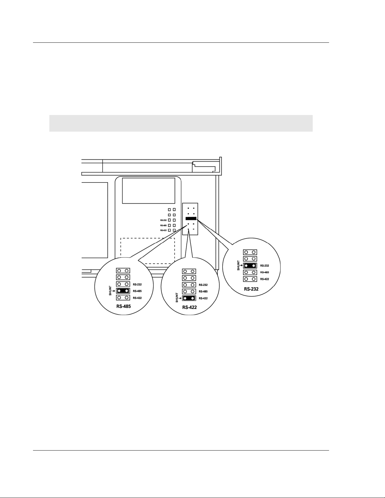
1.3 Setting Debug and Port 0 Configuration Jumpers
The Debug Port operates in RS232 mode only on Series C gateways. No
jumpers are provided for the Debug Port on them.
Before mounting the gateway on the DIN-rail, you must set a jumper for
application Port 0 to select RS-232, RS-422, or RS-485 mode. The port is set at
the factory for RS-232 mode. Verify correct jumper setting before startup to
minimize problems.
Note: Series A gateways have active jumpers for both the Debug and application Port 0.
The following diagram details the jumper position for the ProLinx 5000/6000
series gateways.
Page 14 of 144 ProSoft Technology, Inc.
November 24, 2010
Page 15
5105-103M-PDPS ♦ ProLinx Gateway Start Here
IEC 60870-5-103 Master to PROFIBUS Slave Gateway User Manual
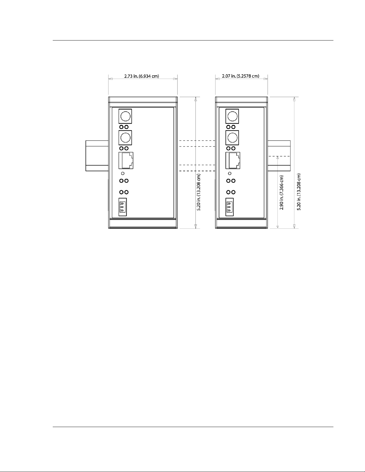
1.4 Mounting the Module on the DIN-rail
ProLinx 5000/6000 Series gateways
ProSoft Technology, Inc. Page 15 of 144
November 24, 2010
Page 16
Start Here 5105-103M-PDPS ♦ ProLinx Gateway
User Manual IEC 60870-5-103 Master to PROFIBUS Slave Gateway
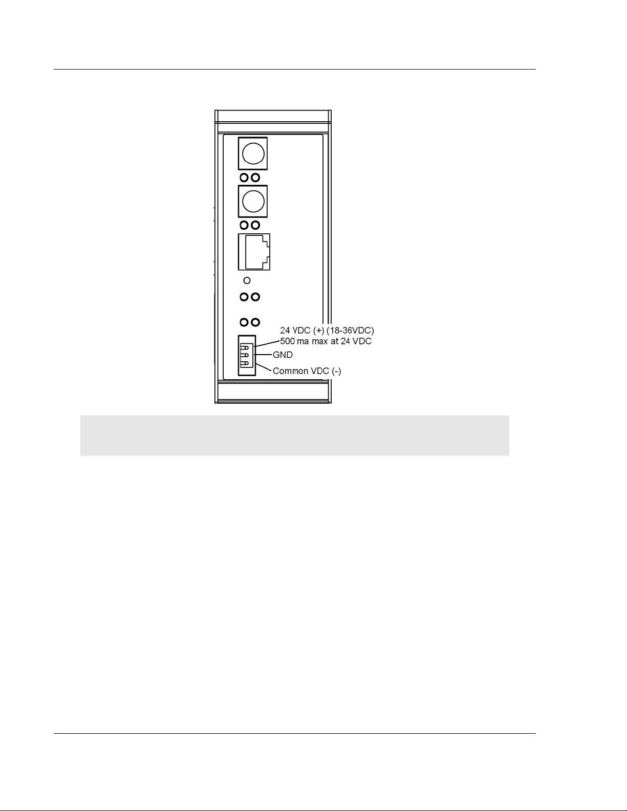
1.5 Connecting Power to the Unit
WARNING: Ensure that you do not reverse polarity when applying power to the gateway. This
could cause damage to the gateway’s internal systems.
Page 16 of 144 ProSoft Technology, Inc.
November 24, 2010
Page 17

5105-103M-PDPS ♦ ProLinx Gateway Start Here
IEC 60870-5-103 Master to PROFIBUS Slave Gateway User Manual
1.6 Configure the Module
Because the task of configuring the ProLinx module can be complicated, ProSoft
Technology has provided a configuration tool called ProSoft Configuration
Builder (PCB) that will help you with the following tasks:
Creating a configuration project
Setting module parameters
Configuring the protocols
o
103M (page 31)
o
PDPS (page 41)
Copying the project to the module.
The following topics of this chapter explain each task step-by-step.
1.6.1 Installing ProSoft Configuration Builder Software
You must install the ProSoft Configuration Builder (PCB) software to configure
the gateway. You can always get the newest version of ProSoft Configuration
Builder from the ProSoft Technology website.
Installing ProSoft Configuration Builder from the ProSoft website
1 Open your web browser and navigate to http://www.prosoft-
technology.com/pcb
2 Click the D
Configuration Builder.
3 Choose S
4 Save the file to your Windows Desktop, so that you can find it easily when
you have finished downloading.
5 When the download is complete, locate and open the file, and then follow the
instructions on your screen to install the program.
If you do not have access to the Internet, you can install ProSoft Configuration
Builder from the ProSoft Solutions Product CD-ROM, included in the package
with your gateway.
OWNLOAD HERE
AVE
or S
AVE FILE
link to download the latest version of ProSoft
when prompted.
ProSoft Technology, Inc. Page 17 of 144
November 24, 2010
Page 18

Start Here 5105-103M-PDPS ♦ ProLinx Gateway
User Manual IEC 60870-5-103 Master to PROFIBUS Slave Gateway
Installing ProSoft Configuration Builder from the Product CD-ROM
1 Insert the ProSoft Solutions Product CD-ROM into the CD-ROM drive of your
PC. Wait for the startup screen to appear.
2 On the startup screen, click P
RODUCT DOCUMENTATION
. This action opens a
Windows Explorer file tree window.
3 Click to open the U
TILITIES
folder. This folder contains all of the applications
and files you will need to set up and configure your gateway.
4 Double-click the S
PCB_*.
EXE
file and follow the instructions on your screen to install the
ETUP CONFIGURATION TOOL
folder, double-click the
software on your PC. The information represented by the "*" character in the
file name is the PCB version number and, therefore, subject to change as
new versions of PCB are released.
Note: Many of the configuration and maintenance procedures use files and other utilities on the
CD-ROM. You may wish to copy the files from the Utilities folder on the CD-ROM to a convenient
location on your hard drive.
Using the Online Help
Most of the information needed to help you use ProSoft Configuration Builder is
provided in a Help System that is always available whenever you are running
ProSoft Configuration Builder. The Help System does not require an Internet
connection.
To view the help pages, start ProSoft Configuration Builder, open the H
menu, and then choose C
ONTENTS
.
ELP
1.6.2 Adding a Module
Begin the process of creating your custom application configuration by selecting
the module type of your ProLinx gateway.
Page 18 of 144 ProSoft Technology, Inc.
November 24, 2010
Page 19
5105-103M-PDPS ♦ ProLinx Gateway Start Here
IEC 60870-5-103 Master to PROFIBUS Slave Gateway User Manual
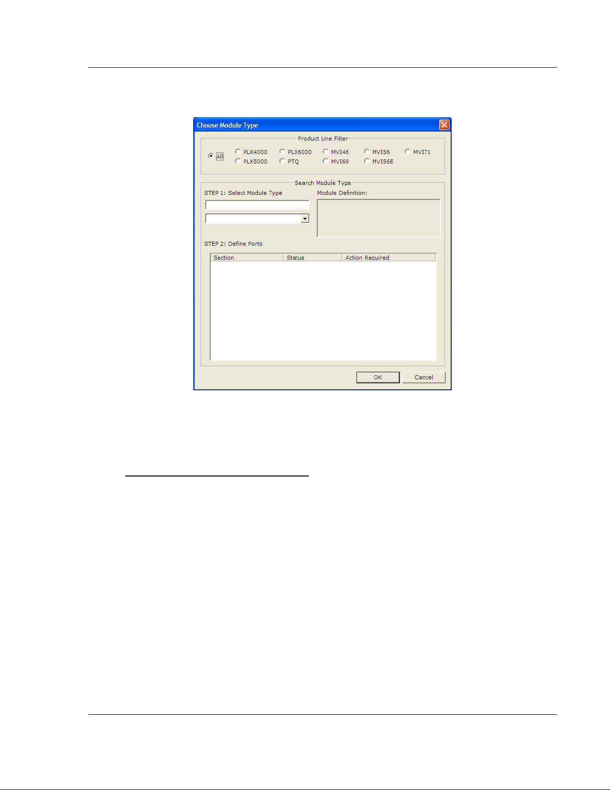
1 Double-click the D
EFAULT MODULE
icon to open the Choose Module Type
dialog box.
2 On the Choose Module Type dialog box, select the M
Or
1 Open the P
2 On the L
To add a module to a different location
1 Right-click the L
ROJECT
OCATION
menu and choose L
menu, choose A
OCATION
folder and choose A
OCATION.
DD MODULE
.
DD MODULE
icon appears.
Or
1 Select the L
2 From the P
OCATION
ROJECT
icon.
menu, select L
OCATION
, and then select A
ODULE
. A new M
type.
ODULE
DD MODULE
.
ProSoft Technology, Inc. Page 19 of 144
November 24, 2010
Page 20
Start Here 5105-103M-PDPS ♦ ProLinx Gateway
User Manual IEC 60870-5-103 Master to PROFIBUS Slave Gateway
1.6.3 Quick Start
Step 1: Configure the Number of Slaves (Sessions)
The IEC 60870-5-103 protocol is a master-slave protocol where the slaves are
typically protection equipments for substations. The 5105-103M-PDPS module
supports a total 16 slaves (sessions) connected to the module's two application
ports.
Note: The actual number of available sessions (slaves) will depend on the total number of
sessions and sectors (configured. The recommended maximum number of sessions is sixteen.
In the example above, the module will only poll sessions 0 to 4. The module
would not poll sessions 5 to 31.
In Step 3, you will configure each session as an actual slave in the network.
Page 20 of 144 ProSoft Technology, Inc.
November 24, 2010
Page 21
5105-103M-PDPS ♦ ProLinx Gateway Start Here
IEC 60870-5-103 Master to PROFIBUS Slave Gateway User Manual
Step 2: Configure the Port Communication Parameters
The user should configure the port communication parameters in order to enable
data transfer between the master and the slave(s). The port communication
parameters include baud rate, parity, RTS ON, RTS OFF, and Minimum Delay.
The IEC 60870-5-103 protocol uses two baud rates: 19200 or 9600 kb/s and
even parity.
Refer to the [IEC-870-5-103 Master Port 0] section in the configuration file in
order to configure the communication parameters for the 103M port:
You must also configure the port jumpers to select the correct communication
mode: RS-232, RS-422, or RS-485.
ProSoft Technology, Inc. Page 21 of 144
November 24, 2010
Page 22
Start Here 5105-103M-PDPS ♦ ProLinx Gateway
User Manual IEC 60870-5-103 Master to PROFIBUS Slave Gateway
Step 3: Configure the Session (Slave) Poll Parameters
According to the IEC 60870-5-103 protocol, the master cyclically polls data from
the slaves. The data is classified as Class 1 or Class 2. Events belong to Class
1, and analog data to Class 2. The module can request data through Class 1 or
Class 2 requests. Responses to control command and general interrogation
commands are also sent as Class 1 data.
Refer to the [IEC-103 Master Session x] section in the configuration file in order
to configure how each slave will be polled.
These parameters include the Data Link Address, which is the slave address that
identifies each piece of protection equipment in the network. There should be a
unique number for each slave in the network. There are also certain parameters
that pertain to how the Class 1 and Class 2 polls will be used for data transfer.
You must enter the number of sectors for each session using the Sector Count
parameter. The module accepts up to five sectors per session.
Note: Actual number of available sectors per session will depend on the total number of sessions
and sectors configured. The recommended maximum number of sectors is three.
Page 22 of 144 ProSoft Technology, Inc.
November 24, 2010
Page 23
5105-103M-PDPS ♦ ProLinx Gateway Start Here
IEC 60870-5-103 Master to PROFIBUS Slave Gateway User Manual
Repeat this step for each session. For example, if you configured 5 sessions
during Step 1, configure Sessions 0 to 4.
ProSoft Technology, Inc. Page 23 of 144
November 24, 2010
Page 24
Start Here 5105-103M-PDPS ♦ ProLinx Gateway
User Manual IEC 60870-5-103 Master to PROFIBUS Slave Gateway
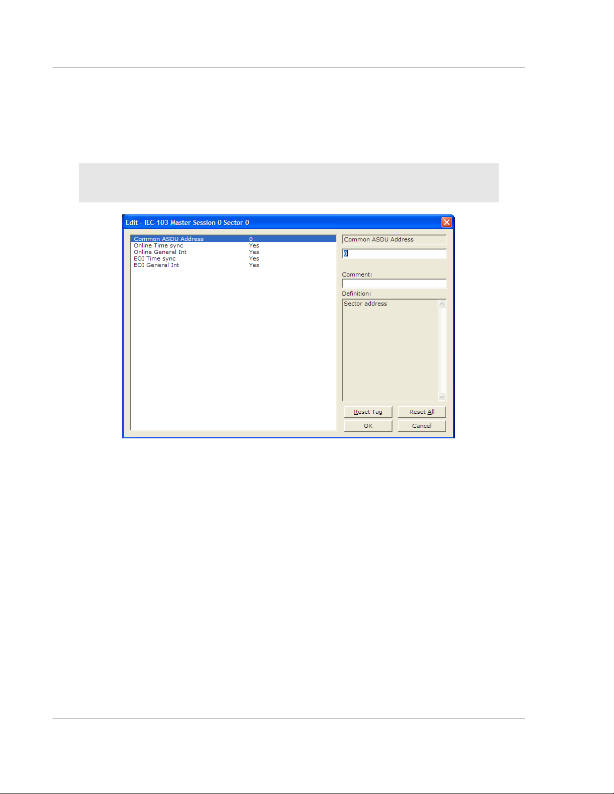
Step 4: Sector (Data Set) Configuration
For each session (slave), you must configure one or more sectors. A sector is a
data set defined by the vendor. Each sector is identified by the Common ASDU
Address parameter in the [IEC-103 Master Session x Sector 0] area in the
configuration. This area also contains some parameters that will affect the
module initialization procedure.
Note: The actual number of available sectors per session will depend on the total number of
sessions and sectors configured. The recommended maximum number of sectors is three.
Repeat this step for each sector used by the application. The module will only
use the sectors configured in the previous step.
Page 24 of 144 ProSoft Technology, Inc.
November 24, 2010
Page 25
5105-103M-PDPS ♦ ProLinx Gateway Start Here
IEC 60870-5-103 Master to PROFIBUS Slave Gateway User Manual
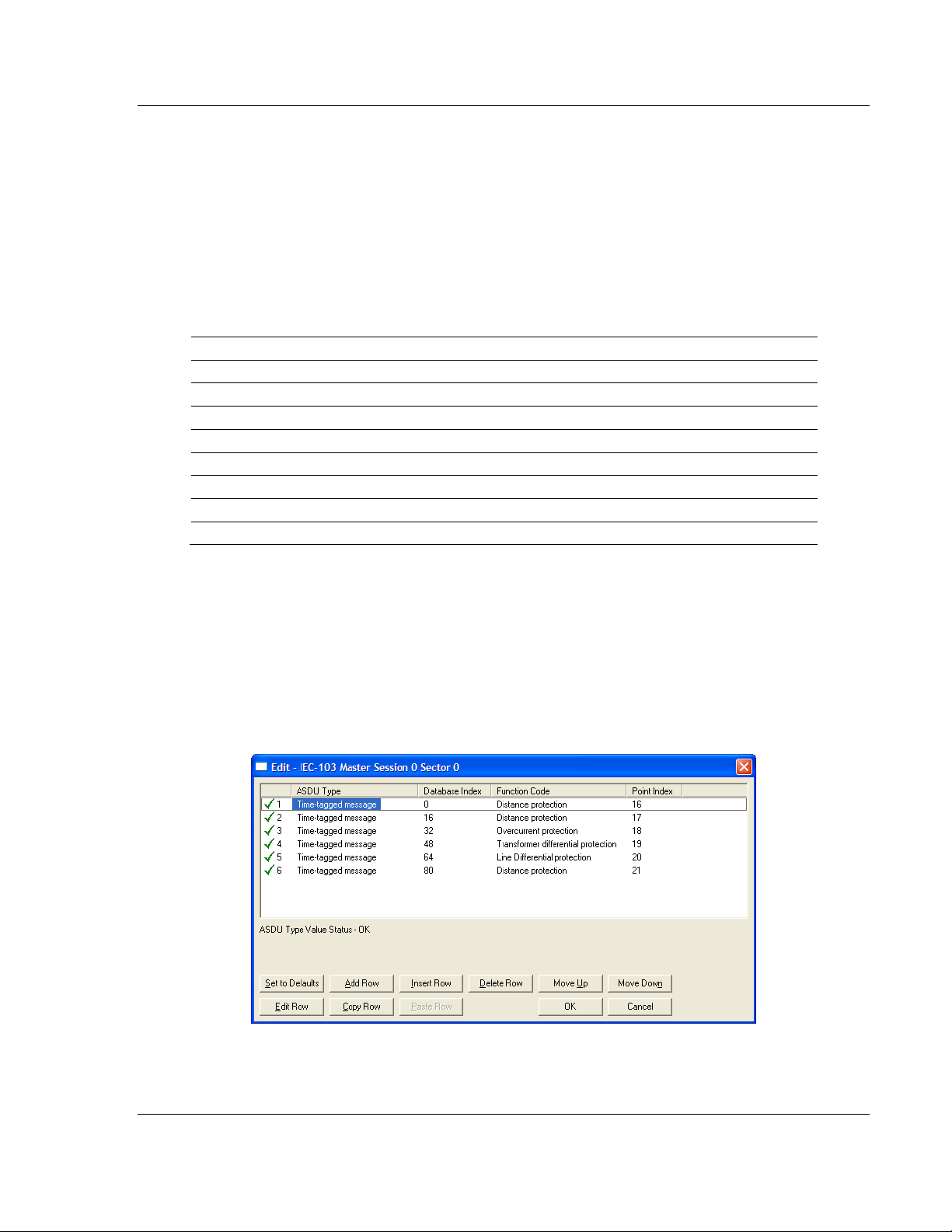
Step 5: Monitor Point Configuration (Monitor Direction)
When a slave receives a Class 1 or Class 2 request from the master, it responds
with a message containing data. Each piece of equipment is normally configured
to respond with specific points when it is being polled with a Class 2 request.
During a Class 2 response, the slave may set a control bit (ACD) to inform the
master that there are new events to be transmitted. Then, the master will send a
Class 1 poll to read the events from the slave.
The IEC 60870-5-103 protocol states that the data is transferred between the
master and slave using an ASDU (Application Service Data Unit) format. Each
format is given by:
Type Identification
Variable Structure Qualifier
Cause Of Transmission
Common Address of ASDU
Function Type
Information Number
Data…
Data…
…
Refer to the protection equipment specification for the following information about
each point:
Type: Type of the message
Function Type: Type of protection function
Information Number: Point Identification
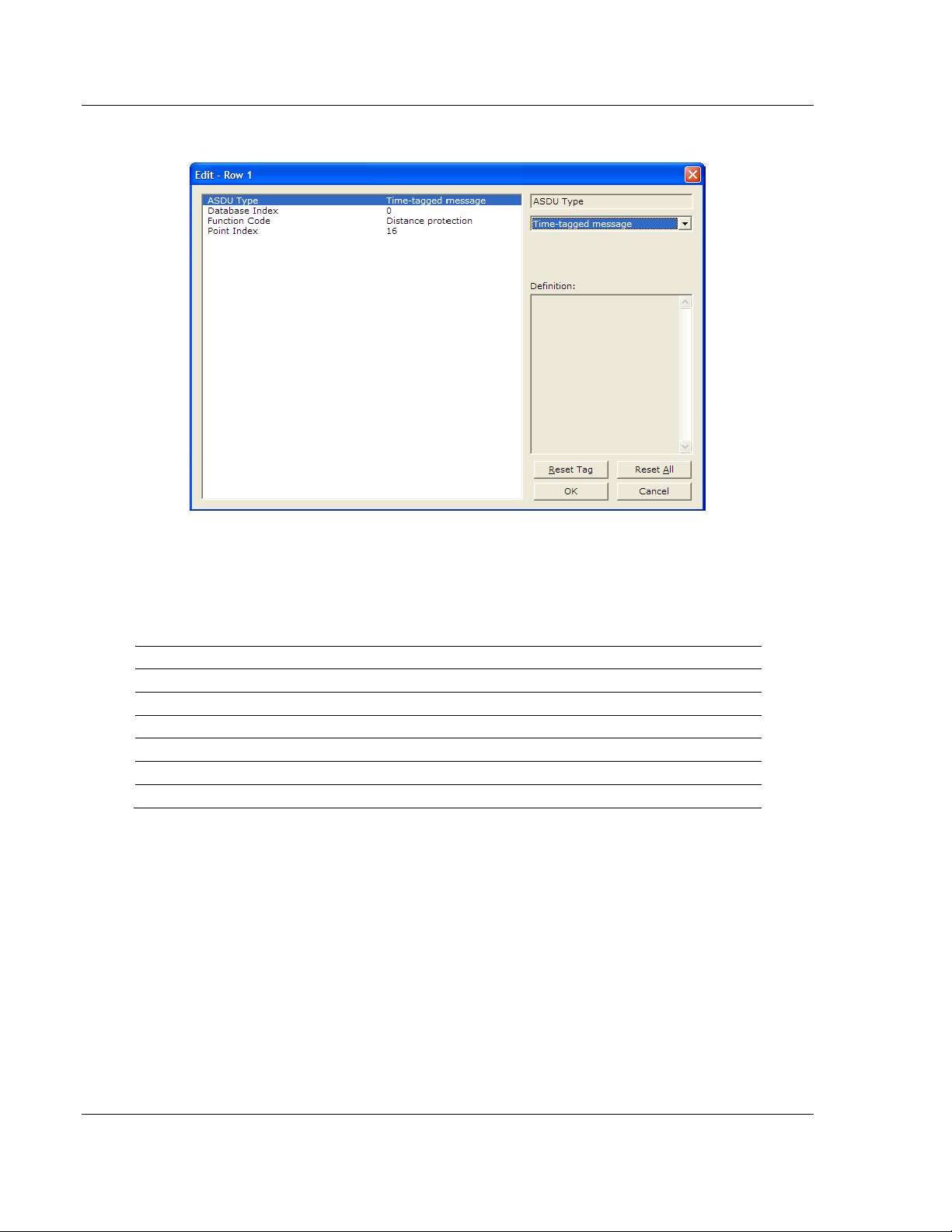
This information identifies each point in the configuration. You must configure the
points that will be updated in the module database when a Class 2 or Class 1
response containing data is sent from the slave. Refer to [IEC-103 M
S
ESSION X SECTOR
0] to configure each point.
ASTER
ProSoft Technology, Inc. Page 25 of 144
November 24, 2010
Page 26
Start Here 5105-103M-PDPS ♦ ProLinx Gateway
User Manual IEC 60870-5-103 Master to PROFIBUS Slave Gateway
For each point, configure the following values.
ASDU Type: ASDU type for the point
Function Type: Function type for the point
Point Index: Information number for the point
Database Index: The module database location where the value will be copied.
The type of addressing will depend on the ASDU type:
ASDU Type DB Addressing
1 Bit address with each point occupying 2 bits
2 Bit address with each point occupying 2 bits
3 Word address with each point occupying 4 words
4 Double-word address for the single float value
5 Byte address with each point occupying 12 bytes
9 Word address with each point occupying 9 words
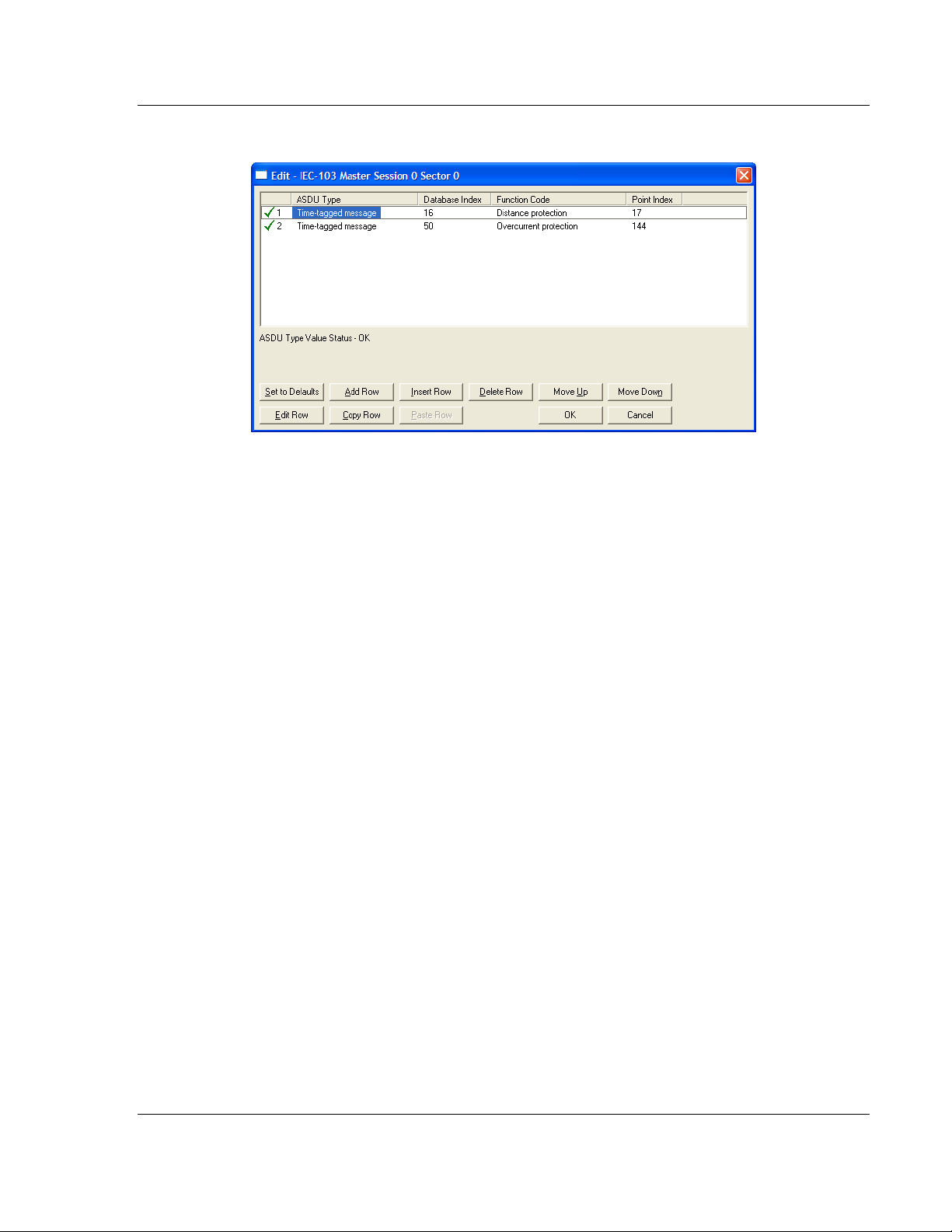
For example, to configure the following points,
Time-tagged message point with information number 17 (teleprotection
active) and distance protection function (128). The value will be copied to bits
0 and 1 in word 1 (second word) in the module database.
Measurands I point with information number 144 (measurands I) and
overcurrent protection function (160). The value will be copied to word 50 in
the module Database.
Page 26 of 144 ProSoft Technology, Inc.
November 24, 2010
Page 27
5105-103M-PDPS ♦ ProLinx Gateway Start Here
IEC 60870-5-103 Master to PROFIBUS Slave Gateway User Manual
Use the following configuration.
Every time the module responds with a Class 1 or Class 2 poll with these points,
the module will copy the value to the database.
All the points configured in this section are sent from the slave to the master. The
protocol specification refers to this data flow as the Monitor Direction.
Repeat this step for each sector.
ProSoft Technology, Inc. Page 27 of 144
November 24, 2010
Page 28
Start Here 5105-103M-PDPS ♦ ProLinx Gateway
User Manual IEC 60870-5-103 Master to PROFIBUS Slave Gateway
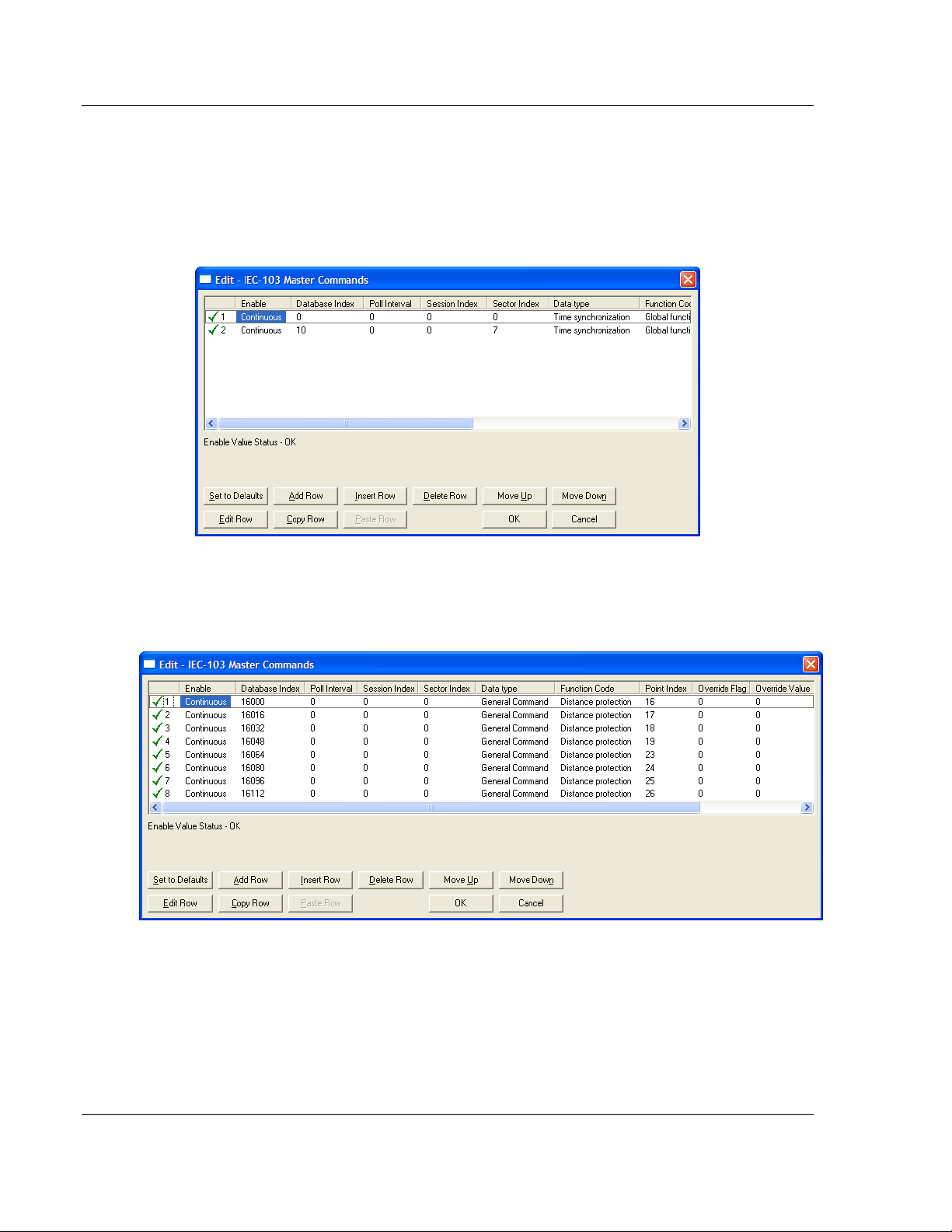
Step 6: Command Configuration (Control Direction)
You can also configure the master to send commands to slaves. The IEC 608705-103 protocol specification refers to this data flow as Control Direction. The
commands include general commands, interrogation requests, and time
synchronization requests. In order to configure a command, refer to the [IEC-103
Master Commands] section:
To send a General Command, you can associate the source data with a register
in the module database to be sent to the remote slave. The following example
will send 8 commands to the slave configured as Session 0/Sector 0. Use bit
addressing to send a General Command.
Refer to the device specification for the Point Index (Information Number) listing
available for control direction.
The module can also send a periodic General Interrogation command in order to
initialize and refresh the event-updated points in its database. The slave keeps a
list of all data subject to General Interrogation.
Page 28 of 144 ProSoft Technology, Inc.
November 24, 2010
Page 29
5105-103M-PDPS ♦ ProLinx Gateway Start Here
IEC 60870-5-103 Master to PROFIBUS Slave Gateway User Manual
Step 7: Set the module’s Data and Time (optional)
If the module will be sending time synchronization commands to the slave, you
must set the date and time on the module (page 122).
Step 8: Transfer the Configuration from the Computer to the module.
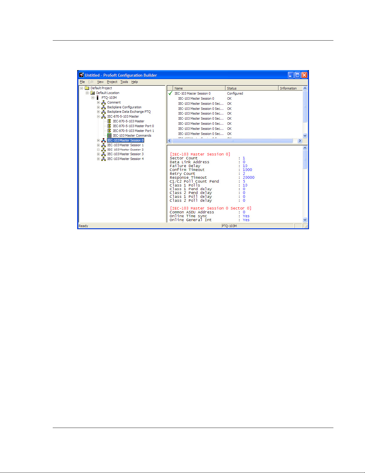
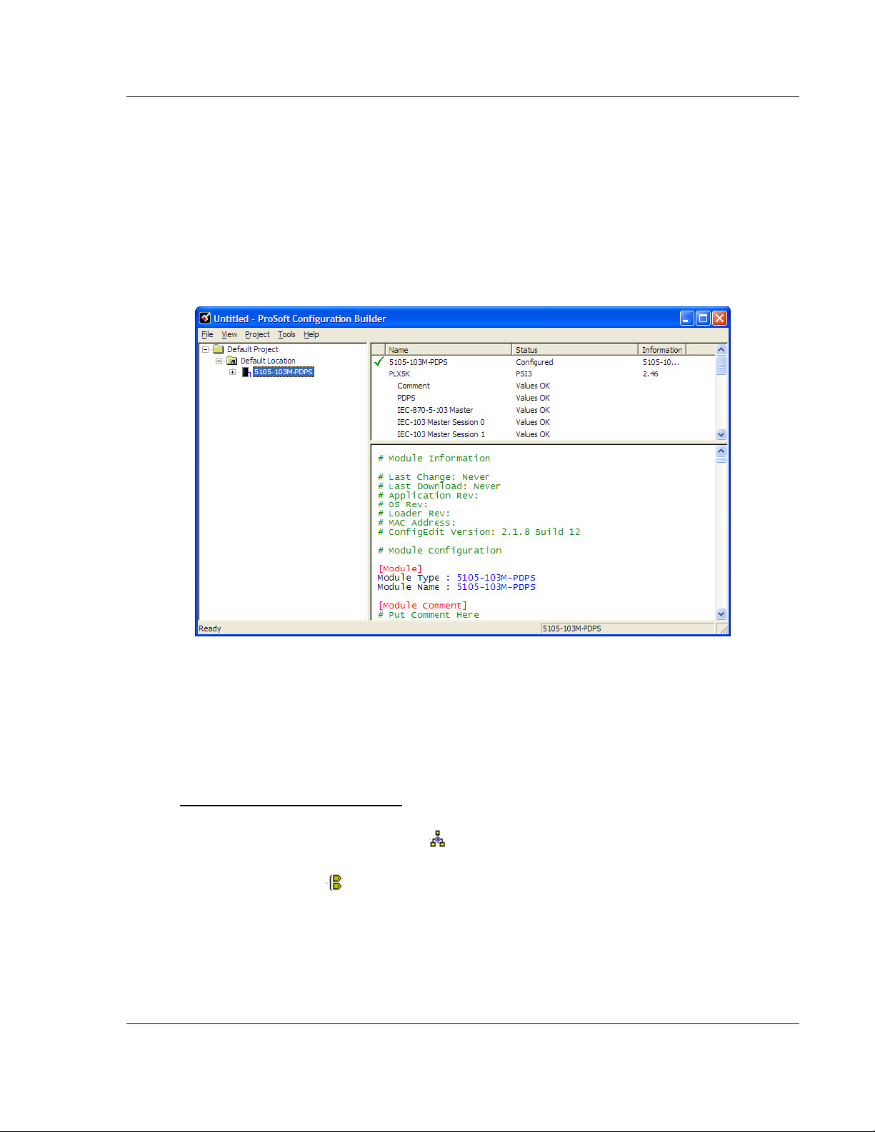
1.6.4 Renaming PCB Objects
Notice that the contents of the information pane and the configuration pane
changed when you added the gateway to the project.
At this time, you may wish to rename the Default Project and Default Location
folders in the tree view.
1 Select the object, and then click the right mouse button to open a shortcut
menu. From the shortcut menu, choose R
ENAME
.
2 Type the name to assign to the object.
3 Click away from the object to save the new name.
Configuring Module Parameters
1 Click on the [+] sign next to the gateway icon to expand gateway information.
2 Click on the [+] sign next to any icon to view gateway information and
configuration options.
3 Double-click any icon to open an Edit dialog box.
4 To edit a parameter, select the parameter in the left pane and make your
changes in the right pane.
5 Click OK to save your changes.
ProSoft Technology, Inc. Page 29 of 144
November 24, 2010
Page 30
Start Here 5105-103M-PDPS ♦ ProLinx Gateway
User Manual IEC 60870-5-103 Master to PROFIBUS Slave Gateway
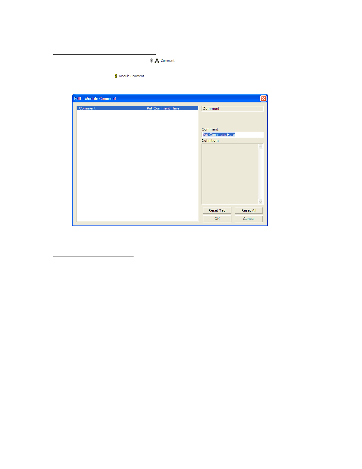
Creating Optional Comment Entries
1 Click the [+] to the left of the icon to expand the module
comments.
2 Double-click the icon. The Edit - Module Comment dialog box
appears.
3 Enter your comment and click OK to save your changes.
Printing a Configuration File
1 Select the gateway icon, and then click the right mouse button to open a
shortcut menu.
2 On the shortcut menu, choose V
IEW CONFIGURATION
. This action opens the
View Configuration window.
3 In the View Configuration window, open the F
ILE
menu, and choose P
RINT.
This action opens the Print dialog box.
4 In the Print dialog box, choose the printer to use from the drop-down list,
select printing options, and then click OK.
Page 30 of 144 ProSoft Technology, Inc.
November 24, 2010
Page 31

5105-103M-PDPS ♦ ProLinx Gateway Start Here
IEC 60870-5-103 Master to PROFIBUS Slave Gateway User Manual
1.7 103M Protocol Configuration
The following is excerpted from a configuration file showing typical examples
used for configuration of the 103M driver. A default configuration file for each
module application that includes the 103M interface card is available for
download from the www.prosoft-technology.com web site. This default
configuration can easily form the basis for a working solution. This file can either
be downloaded from the ProSoft web site at www.prosoft-technology.com, or
transferred from the module.
The configuration file contains the following topics:
[Section] Description
[IEC-870-5-103 Master] General configuration for the driver.
[IEC-870-5-103 Master Port n] Configuration for one of the application ports.
[IEC-103 Master Session x] Definition of each control unit.
[IEC-103 Master Session x Sector y] Definition for each sector in the controlled unit.
[IEC-103 Master Commands] Command list to control slave units.
1.7.1 [IEC-103 Master Commands]
This section can contain up to 1000 user defined commands to be executed by
the module and sent to the controlled devices. There is no need to place Class 1
or Class 2 polls in this list for the controlled devices as the master driver for each
port will execute these automatically when the port is idle. In order for the port to
be idle, make sure that there is idle time available, and that the commands do not
constantly utilize the ports.
ProSoft Technology, Inc. Page 31 of 144
November 24, 2010
Page 32

Start Here 5105-103M-PDPS ♦ ProLinx Gateway
User Manual IEC 60870-5-103 Master to PROFIBUS Slave Gateway
Enable Code
0 = Disabled
1 = Enabled, will execute using Poll Interval parameter (page 32) (seconds)
2 = Conditional (executed when point in database changes)
This field defines whether the command is to be executed, and under what
conditions. To disable the command, set this parameter to 0 (Disabled). You can
still execute commands through the processor, using a Special Function block.
To enable the command, set this parameter to 1.
Set the Poll Interval Time to 0 to execute the command during each scan of
the command list.
Set the Poll Interval Time to a value in seconds, to execute the command at
the specified interval (page 32).
To execute the command only if the internal data associated with the command
changes, set this parameter to 2. This value is valid only for write commands.
Database Index
Database Index is the location in the module's database to use as the source for
the data in the command. Refer to Data Type for specific information on
addressing (page 33).
The data type field determines the meaning of the database index as follows:
Type Description DB Index type
6 Clock synchronization NA
7 General interrogation NA
20 General Command Bit address
Poll Interval
This parameter specifies the minimum frequency at which the module should
execute the command when the Enable Code is set to one 1. The value is
entered in units of seconds. For example, to execute a command every 10
seconds, enter a value of 10 in the field. A value of 0 for the parameter implies
that the command should be executed every scan of the list, as quickly as
possible.
Session Index
0 to 31
Session Index represents the session index in the module to associate with the
command. This index is set when the session is read in from this file. The range
of values for this field is 0 to 31.
Sector Index
0 to 4
Sector Index represents the sector index for the specific session. There are a
maximum of five (5) sectors per session.
Page 32 of 144 ProSoft Technology, Inc.
November 24, 2010
Page 33

5105-103M-PDPS ♦ ProLinx Gateway Start Here
IEC 60870-5-103 Master to PROFIBUS Slave Gateway User Manual
Data Type
Data type file represents the ASDU type as follows:
Type Description
6 Clock synchronization
7 General interrogation
20 General Command
Function Code
Code Definition
128 Distance protection
160 Overcurrent protection
176 Transformer differential protection
192 Line Differential protection
255 Global function type
133 Meter Data for SIEMENS Devices
1 Reset Process
2 Class 2 Polls
x User-defined
Note: The last item in the Function Code dropdown list is user-defined. If you select U
SER DEFINED
from the dropdown list, a text box will appear below the list. You may enter any function code in
this text box that will be accepted by the destination slave.
Point Index
Point Index specifies the address in the remote slave device of the point to
interact with.
Index Value Description
1 Bit address with each point occupying 2 bits
2 Bit address with each point occupying 2 bits
3 Word address with each point occupying 4 words
4 Double-word address for the single float value
5 Byte address with each point occupying 12 bytes
9 Word address with each point occupying 9 words
Override Flag
0 or 1
Override Flag field is used for general commands to determine the value to be
written. If the override flag is clear (0), the value in the database will be utilized. If
the override flag is set (1), the value specified in the override value field will be
used.
ProSoft Technology, Inc. Page 33 of 144
November 24, 2010
Page 34

Start Here 5105-103M-PDPS ♦ ProLinx Gateway
User Manual IEC 60870-5-103 Master to PROFIBUS Slave Gateway
Override Value
If the Override Flag is set to "Yes", you can use this setting to always force a
control parameter to a fixed value. Use Enable code C
database value for the command to determine when the value should be written.
ONDITIONAL
and the
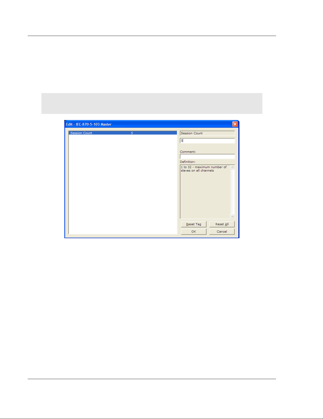
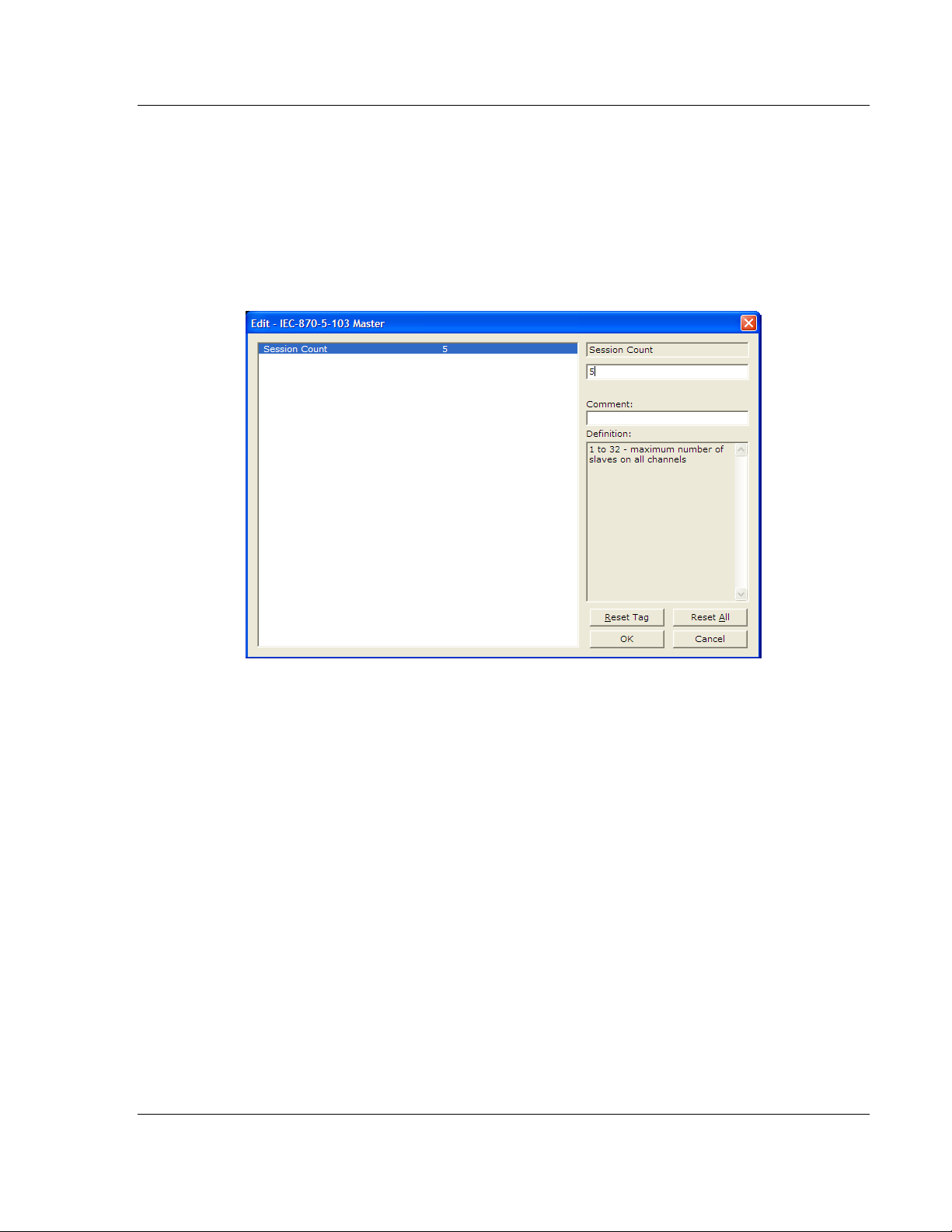
1.7.2 [IEC-870-5-103 Master]
This section establishes the total number of slaves to communicate with through
both application serial ports.
[IEC-870-5-103 Master]
Session Count : 1 #1 to 32 - maximum number of slaves on all channels
Session Count
1 to 16
This parameter specifies the maximum number of sessions (slaves) to interface
with the module's 103M application ports. This value represents the total number
of slaves on all ports.
1.7.3 [IEC-870-5-103 Master Port x]
These settings configure the communication parameters for each application port
on the module. The following illustration shows typical settings for a Master port.
Page 34 of 144 ProSoft Technology, Inc.
November 24, 2010
Page 35

5105-103M-PDPS ♦ ProLinx Gateway Start Here
IEC 60870-5-103 Master to PROFIBUS Slave Gateway User Manual
Baud Rate
Baud Rate Value
This is the baud rate to be used on the port. Enter the baud rate as a value. For
example, to select 19K baud, enter 19200. Valid entries for this field include: 110,
150, 300, 600, 1200, 2400, 4800, 9600, 19200 (may also enter as 192 or 1920),
28800 (may also enter 288 or 2880), 38400 (may also enter as 384 or 3840),
57600 (may also enter as 576 or 5760), and 115200 (may also enter as 115,
1152, or 11520).
Parity
N, O, E, M, or S
This parameter sets the parity to be used on the port. The values correspond to
the following settings: N=None, O=Odd, E=Even, M=Mark and S=Space.
Note: The 103M specification supports only Even Parity.
RTS On
0 to 65535 milliseconds
This parameter sets the number of milliseconds to delay after Ready To Send
(RTS) is asserted before data will be transmitted.
RTS Off
0 to 65535 milliseconds
This parameter sets the number of milliseconds to delay after the last byte of
data is sent before the RTS modem signal will be set low.
Minimum Delay
1 to 60000 milliseconds
This parameter specifies the minimum number of milliseconds to delay before
sending the message (setting RTS high). This can be used when the serial
network requires time for units to turn off their transmitters.
Receive Timeout
1 to 65535 milliseconds
This value represents the number of milliseconds to wait on a port from the time
the first character is received until the last character in the longest message is
received. This parameter will be dependent on the baud rate. A value of 2000
should work with most applications.
Single char ACK F0, 1, or 3
Yes or No
This parameter specifies if the signal E5 character will be used for ACK
messages.
ProSoft Technology, Inc. Page 35 of 144
November 24, 2010
Page 36

Start Here 5105-103M-PDPS ♦ ProLinx Gateway
User Manual IEC 60870-5-103 Master to PROFIBUS Slave Gateway
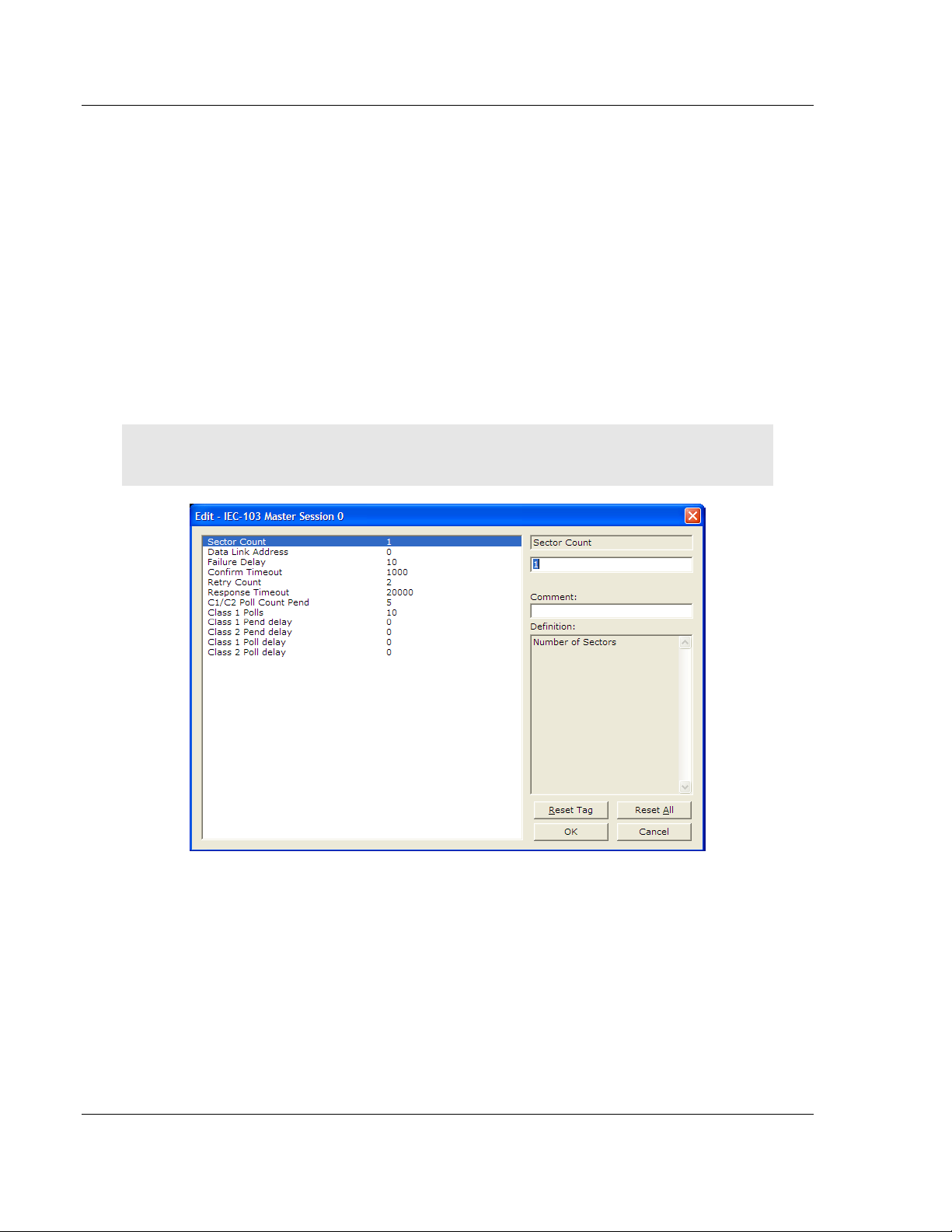
1.7.4 [IEC-103 Master Session x]
This section defines Session y, which runs on Port x. The Session Count
parameter in the [IEC-870-5-103 Master] section of the configuration (page 34)
determines the number of sessions (controlled devices) for this port.
The sessions are referenced by a zero-based index value. For example, if the
module is configured for four sessions, the configuration file should contain
sections for Sessions 0 to 3 (that is, [IEC-103 Master Session 0] to [IEC-103
Master Session 3]).
The parameters in [IEC-103 Master Session y] define the characteristics of the
specific controlled device to interface.
Communication Port
0 or 1
This parameter sets the port to which the controlled device is connected. On this
module, values of 0 and 1 are permitted.
Sector Count
1 to 3
This parameter sets the number of Sectors (separate databases or Multiple
Application Layer ASDU addresses) contained in this Session (controlled
device). This version of the application supports 1 to 3 sectors for each session.
Data Link Address
0 to 254
This parameter uniquely defines the data link address for this unit on the
communication channel. The ranges of values are from 0 to 254. Address 255 is
the broadcast address.
Failure Delay
0 to 2000 seconds
This parameter sets the minimum number of seconds to delay before polling this
session when it is not online. This parameter is only used in unbalanced mode.
Confirm Timeout
0 to 4,294,967,295 (two raised to the power of 32, minus one) milliseconds
This parameter sets the number of milliseconds to wait for a confirm response
from the controlled device.
Retry Count
0 to 255
In balanced mode, this parameter specifies the number of retries (0 to 255) if a
response is not received. In unbalanced mode, this parameter is ignored.
Page 36 of 144 ProSoft Technology, Inc.
November 24, 2010
Page 37

5105-103M-PDPS ♦ ProLinx Gateway Start Here
IEC 60870-5-103 Master to PROFIBUS Slave Gateway User Manual
C1/C2 Poll Count Pend
0 to 65535
This parameter sets the maximum number of Class 1 and Class 2 polls
performed on this session before trying the next session. This parameter
prevents a session from monopolizing the communication port.
Class 1 Polls
0 to 100
This parameter sets the maximum number of Class 1 polls performed on this
session before switching to another session. This parameter prevents a session
from monopolizing the communication port.
Class 1 Pend Delay
0 to 4,294,967,295 (two raised to the power of 32, minus one) milliseconds
This parameter sets the minimum number of milliseconds to delay between Class
1 polls for pending data.
Class 2 Pend Delay
0 to 4,294,967,295 (two raised to the power of 32, minus one) milliseconds
This parameter sets the minimum number of milliseconds to delay between Class
2 polls for pending data.
Class 1 Poll Delay
0 to 4,294,967,295 (two raised to the power of 32, minus one) milliseconds
This parameter sets the minimum number of milliseconds to delay between each
Class 1 poll.
Class 2 Poll Delay
0 to 4,294,967,295 (two raised to the power of 32, minus one) milliseconds
This parameter sets the minimum number of milliseconds to delay between each
Class 2 poll.
Auto Clock Req Mode
0=Sync Only, 1=Load delay/sync, 2=Acquire delay/load delay/sync
This parameter specifies the method used to perform automatic clock
synchronization. 0 performs a synchronization without delay, 1 performs
synchronization using the fixed Propagation Delay and 2 computes the delay and
use this value when synchronization takes place.
Propagation Delay
0 to 65535
This parameter sets the fixed propagation delay to be utilized if the Auto Clock
Req Mode parameter is set to a value of 1.
ProSoft Technology, Inc. Page 37 of 144
November 24, 2010
Page 38

Start Here 5105-103M-PDPS ♦ ProLinx Gateway
User Manual IEC 60870-5-103 Master to PROFIBUS Slave Gateway
Response Timeout
0 to 4,294,967,295 milliseconds
This parameter sets the maximum number of milliseconds to wait for a
confirmation from the controlled station to a request from this module.
ACTTERM with setpoint
Yes or No
This parameter determines if an ACTTERM will be sent. If the parameter is set to
Yes, then setpoint commands will issue an ACTTERM when the command is
complete. If the parameter is set to No, ACTCON is the last response to a
setpoint command.
1.7.5 [IEC-103 Master Session x Sector y]
This section defines Sector z, which belongs to Session y. The Sector Count
parameter (page 36) in the [IEC-870-5-103 Master Session y] section specifies
the number of sectors for the session.
Each sector has a corresponding [IEC-103 Master Session y Sector z] section,
where y represents the session index and z represents the sector index.
The sectors are referenced by a zero-based index value. For example, if Session
0 is configured for four sectors, the configuration file should contain sections for
Sectors 0 to 3 (that is, [IEC-103 Master Session 0 Sector 0] to [IEC-103 Master
Session 0 Sector 3]).
Page 38 of 144 ProSoft Technology, Inc.
November 24, 2010
Page 39

5105-103M-PDPS ♦ ProLinx Gateway Start Here
IEC 60870-5-103 Master to PROFIBUS Slave Gateway User Manual
Common ASDU Address
0 to 255
This parameter sets the common ASDU address to association with this sector of
the specified session. This parameter is usually set the same as the Data Link
Address when only one sector is used.
Online Time Sync
Yes or No
This parameter specifies if the sector in the controlled device will be sent a time
synchronization command when the unit is first recognized as being online. This
should only be used for devices that do not send an EOI message after
initializing.
Online General Int
Yes or No
This parameter specifies if the sector in the controlled device will be sent a
general interrogation command when the unit is first recognized as being online.
This should only be used for devices that do not send an EOI message after
initializing.
EOI Time Sync
Yes or No
This parameter specifies if the sector in the controlled device will be sent a time
synchronization command after this module received an EOI message from the
controlled unit.
EOI General Int
Yes or No
This parameter specifies if the sector in the controlled device will be sent a
general interrogation command after this module received an EOI message from
the controlled unit.
ASDU Type
This field contains the ASDU type code for the data contained in the message.
1 = Time-tagged message (bit addressed with 2 bits/point)
2 = Time-tagged message with relative time (bit addressed with 2 bits/point)
3 = Measurands I (4 word values using word address using double-word
address)
4 = Time-tagged measurands with relative time (1 float value)
5 = Identification (12 characters using a byte address)
9 = Measurands II (9 word values using word address)
205 = Siemens meter data
ProSoft Technology, Inc. Page 39 of 144
November 24, 2010
Page 40

Start Here 5105-103M-PDPS ♦ ProLinx Gateway
User Manual IEC 60870-5-103 Master to PROFIBUS Slave Gateway
Database Index
Database Index is the location in the module's database to use as the source for
the data in the command. Refer to Data Type for specific information on
addressing (page 33).
The data type field determines the meaning of the database index as follows:
Type Description DB Index type
6 Clock synchronization NA
7 General interrogation NA
20 General Command Bit address
Function Code
Code Definition
128 Distance protection
160 Overcurrent protection
176 Transformer differential protection
192 Line Differential protection
133 For SIEMENS ASDU type 205
255 Global function type
x User-defined
Note: The last item in the Function Code dropdown list is user-defined. If you select U
SER DEFINED
from the dropdown list, a text box will appear below the list. You may enter any function code in
this text box that will be accepted by the destination slave.
Point Index
Point Index specifies the address in the remote slave device of the point to
interact with.
Index Value Description
1 Bit address with each point occupying 2 bits
2 Bit address with each point occupying 2 bits
3 Word address with each point occupying 4 words
4 Double-word address for the single float value
5 Byte address with each point occupying 12 bytes
9 Word address with each point occupying 9 words
Page 40 of 144 ProSoft Technology, Inc.
November 24, 2010
Page 41

5105-103M-PDPS ♦ ProLinx Gateway Start Here
IEC 60870-5-103 Master to PROFIBUS Slave Gateway User Manual
1.8 PDPS Protocol Configuration
The following illustration from ProSoft Configuration Builder shows the
PROFIBUS Slave configuration for a ProLinx PDPS module.
1.8.1 [PROFIBUS SLAVE]
The PROFIBUS Slave section contains the data that applies to the PROFIBUS
Slave parameters.
Slave Address
0 to 125
The parameter specifies the node address on the PROFIBUS network for the
slave emulated in the module. Each node on the network must have a unique
address.
Note: Although valid PROFIBUS Node addresses range from 0 to 125, Node 0 is not a valid node
number for a Slave module and that Nodes 0, 1, and 2 are usually reserved for PROFIBUS
Masters. Users are advised to use Node numbers 3-125
Swap Input Bytes
Yes or No
This parameter specifies if the data in the input data area of the module is to be
byte swapped. If the order of the bytes in the words stored in the database is not
correct, use this option. A value of Yes causes the module’s program to swap the
bytes in each word. A value of No indicates no byte swapping will occur.
ProSoft Technology, Inc. Page 41 of 144
November 24, 2010
Page 42

Start Here 5105-103M-PDPS ♦ ProLinx Gateway
User Manual IEC 60870-5-103 Master to PROFIBUS Slave Gateway
Swap Output Bytes
Yes or No
This parameter specifies if the data in the output data area of the module is to be
byte swapped. If the order of the bytes in the words stored in the database is not
correct, use this option. A value of Yes causes the module’s program to swap the
bytes in each word. A value of No indicates no byte swapping will occur.
Comm Failure Mode
No xfer on fail
Xfer on comm fail
This parameter sets the data transfer mode of the module's PROFIBUS output
image to the internal database when a communication failure on the PROFIBUS
interface is detected. If the parameter is set to "No xfer on fail", the output image
will continue to be transferred. If the parameter is set to "xfer on comm fail", the
output image will not be transferred and the last values will be retained.
Comm Timeout Multiplier
1 to 10
This parameter sets the communication timeout value for the module. The value
entered is multiplied by 125 milliseconds to determine the actual timeout value.
For example, a value of 1 specifies a communication timeout of 125 milliseconds.
Use Database Paging
Yes or No
This Parameter Enables or disables user access to the PDPS’s Database area
outside the section reserved for the PROFIBUS Protocol in the range of Word
400 to Word 3999.
Page 42 of 144 ProSoft Technology, Inc.
November 24, 2010
Page 43

5105-103M-PDPS ♦ ProLinx Gateway Start Here
IEC 60870-5-103 Master to PROFIBUS Slave Gateway User Manual
1.8.2 Set_Param (SAP61)
ProSoft PROFIBUS Slave (PDPS) devices have a configurable parameter for
SPC3 User Prm Byte. The following illustrations show the value of this parameter
in Sycon, the configuration tool for ProLinx PROFIBUS DPV0 Master devices,
and in ProSoft Configuration Builder for PROFIBUS, the configuration tool for
ProSoft and ProLinx PROFIBUS DPV1 Master devices.
ProSoft Technology, Inc. Page 43 of 144
November 24, 2010
Page 44

Start Here 5105-103M-PDPS ♦ ProLinx Gateway
User Manual IEC 60870-5-103 Master to PROFIBUS Slave Gateway
Parameter Data Structure
SPC3 evaluates the first seven data bytes (without user prm data), or the first
eight data bytes (with user prm data). The first seven bytes are specified
according to the standard. The eighth byte is used for SPC3-specific
communications. The additional bytes are available to the application.
Byte Bit Position Designation
7 6 5 4 3 2 1 0
0 Lock
Reg
1
2
3
4
5
6
7
8 to 243
Byte 7 Spec_User_Prm_Byte
Bit Name Significance Default State
0 Dis_Startbit The start bit monitoring in the receiver
1 Dis_Stopbit Stop bit monitoring in the receiver is
2 WD_Base This bit specifies the time base used to
3 to 4 Res To be parameterized with 0 0
5 Publisher_Enable DXB-publisher-functionality of the
6 to 7 Res To be parameterized with 0 0
Unio
Req
Sync
Req
Free
Req
WD on Res Res Res Station status
is switched off with this bit
switched off with this bit
clock the watchdog.
WD_Base = 0: time base 10 ms
WD_Base = 1: time base 1 ms
SPC3 is activated with this bit
WD_Fact_1
WD_Fact_2
MinTSDR
Ident_Number_High
Ident_Number_Low
Group_Ident
Spec_User_Prm_Byte
User_Prm_Data
Dis_Startbit = 1,
That is, start bit monitoring is disabled.
Dis_Stopbit = 0
That is, stop bit monitoring is enabled
WD_Base = 0
That is, the time base is 10 ms.
Publisher_Enable = 0, DXB-requesttelegrams are ignored;
Publisher_Enable = 1, DXB-requesttelegram are processed
Page 44 of 144 ProSoft Technology, Inc.
November 24, 2010
Page 45

5105-103M-PDPS ♦ ProLinx Gateway Start Here
IEC 60870-5-103 Master to PROFIBUS Slave Gateway User Manual
1.9 Using the CommonNet Data Map
The Data Map section allows you to copy data between areas in the gateway's
internal database.
You can copy a maximum of 100 registers per Data Map command, and you can
configure a maximum of 200 separate copy commands.
You can copy data from the error or status tables in upper memory to internal
database registers in the User Data memory area.
You can rearrange the byte and/or word order during the copy process. For
example, by rearranging byte or word order, you can convert floating-point values
to the correct format for a different protocol.
You can also use the Data Map to condense widely dispersed data into one
contiguous data block, making it easier to access.
ProSoft Technology, Inc. Page 45 of 144
November 24, 2010
Page 46

Start Here 5105-103M-PDPS ♦ ProLinx Gateway
User Manual IEC 60870-5-103 Master to PROFIBUS Slave Gateway
1.9.1 From Address
0 to highest Status Data address
This field specifies the beginning internal database register address for the copy
operation. This address can be any valid address in the User Data Area or the
Status Data Area of the gateway.
1.9.2 To Address
0 to 3999
This parameter specifies the beginning destination register address for the copy
operation. This address must always be within the User Data registers area.
Take care to specify a destination address that will not overwrite data that has
been stored in memory by one of the communication protocols running on the
gateway.
1.9.3 Register Count
1 to 100
This parameter specifies the number of registers to copy.
Page 46 of 144 ProSoft Technology, Inc.
November 24, 2010
Page 47

5105-103M-PDPS ♦ ProLinx Gateway Start Here
IEC 60870-5-103 Master to PROFIBUS Slave Gateway User Manual
1.9.4 Swap Code
NO C
HANGE
You may need to swap the order of the bytes in the registers during the copy
process in order to change the alignment of bytes between dissimilar protocols.
This parameter is helpful when dealing with floating-point or other multi-register
values, as there is no standard method of storage of these data types in slave
devices.
The following table defines the values and their associated operations:
, W
ORD SWAP
, W
ORD AND BYTE SWAP
, B
YTE SWAP
Swap Code Description
No Swap No change is made in the byte ordering (1234 = 1234)
Word Swap The words are swapped (1234=3412)
Word and
Byte Swap
Bytes The bytes in each word are swapped (1234=2143)
The words are swapped, then the bytes in each word are swapped (1234=4321)
ProSoft Technology, Inc. Page 47 of 144
November 24, 2010
Page 48

Start Here 5105-103M-PDPS ♦ ProLinx Gateway
User Manual IEC 60870-5-103 Master to PROFIBUS Slave Gateway
1.9.5 Delay Preset
This parameter sets an interval for each Data Map copy operation. The value you
put for the Delay Preset is not a fixed amount of time. It is the number of firmware
scans that must transpire between copy operations.
The firmware scan cycle can take a variable amount of time, depending on the
level of activity of the protocol drivers running on the ProLinx gateway and the
level of activity on the gateway's communication ports. Each firmware scan can
take from 1 to several milliseconds to complete. Therefore, Data Map copy
operations cannot be expected to happen at regular intervals.
If multiple copy operations (several rows in the Data map section) happen too
frequently or all happen in the same update interval, they could delay the process
scan of the gateway protocols, which could result in slow data updates or missed
data on communication ports. To avoid these potential problems, you should set
the Delay Preset to different values for each row in the Data Map section and set
them to higher, rather than lower, numbers.
For example, Delay Preset values below 1000 could begin to cause a noticeable
delay in data updates through the communication ports. And you should not set
all Delay Presets to the same value. Instead, use different values for each row in
the Data Map such as 1000, 1001, and 1002 or any other different Delay Preset
values you like. This will prevent the copies from happening concurrently and
prevent possible process scan delays.
Page 48 of 144 ProSoft Technology, Inc.
November 24, 2010
Page 49

5105-103M-PDPS ♦ ProLinx Gateway Start Here
IEC 60870-5-103 Master to PROFIBUS Slave Gateway User Manual
1.10 Printing a Configuration File
1 Select the gateway icon, and then click the right mouse button to open a
shortcut menu.
2 On the shortcut menu, choose V
View Configuration window.
3 In the View Configuration window, open the F
This action opens the Print dialog box.
4 In the Print dialog box, choose the printer to use from the drop-down list,
select printing options, and then click OK.
IEW CONFIGURATION
ILE
menu, and choose P
. This action opens the
RINT.
ProSoft Technology, Inc. Page 49 of 144
November 24, 2010
Page 50

Start Here 5105-103M-PDPS ♦ ProLinx Gateway
User Manual IEC 60870-5-103 Master to PROFIBUS Slave Gateway
1.11 Downloading a File from PC to the Module
1 Verify that your PC is connected to the gateway with a null-modem serial
cable connected to the serial port on your PC and the serial port on the
gateway
2 Open the P
3 On the M
scans for communication ports on your PC. When the scan is complete, the
Download dialog box opens.
ROJECT
ODULE
menu, and then choose M
menu, choose D
OWNLOAD.
Wait while ProSoft Configuration
ODULE
.
4 Select the
5 Click the D
PORT
to use for the download.
OWNLOAD
button.
Page 50 of 144 ProSoft Technology, Inc.
November 24, 2010
Page 51

5105-103M-PDPS ♦ ProLinx Gateway Diagnostics and Troubleshooting
IEC 60870-5-103 Master to PROFIBUS Slave Gateway User Manual
2 Diagnostics and Troubleshooting
In This Chapter
Using ProSoft Configuration Builder (PCB) for Diagnostics................... 52
Main Menu ............................................................................................. 56
Database View Menu ............................................................................ 59
PROFIBUS Slave Menu ........................................................................ 61
IEC-103 Master Driver Menu ................................................................. 69
IEC-870-Master Command List Menu ................................................... 73
Port Configuration Menu........................................................................ 74
Port Status Menu ................................................................................... 75
Data Analyzer ........................................................................................ 76
Session Configuration Menu ................................................................. 81
Sector Configuration Menu .................................................................... 82
Sector Database Menu .......................................................................... 83
Data Map Menu ..................................................................................... 84
LED Indicators ....................................................................................... 85
Frequently Asked Questions ................................................................. 86
There are two ways to troubleshoot ProLinx Gateways:
Using the LEDs located on the front of the gateway
Using the Debug port that provides a view into the gateway's internal
database.
ProSoft Technology, Inc. Page 51 of 144
November 24, 2010
Page 52

Diagnostics and Troubleshooting 5105-103M-PDPS ♦ ProLinx Gateway
User Manual IEC 60870-5-103 Master to PROFIBUS Slave Gateway
2.1 Using ProSoft Configuration Builder (PCB) for Diagnostics
The Configuration and Debug menu for this gateway is arranged as a tree
structure, with the Main menu at the top of the tree, and one or more submenus
for each menu command. The first menu you see when you connect to the
gateway is the Main menu.
Because this is a text-based menu system, you enter commands by typing the
[command letter] from your computer keyboard in the Diagnostic window in
ProSoft Configuration Builder (PCB). The gateway does not respond to mouse
movements or clicks. The command executes as soon as you press the
[
COMMAND LETTER
[
COMMAND LETTER
] — you do not need to press [E
NTER].
When you type a
], a new screen will be displayed in your terminal application.
2.1.1 Required Hardware
You can connect directly from your computer’s serial port to the serial port on the
gateway to view configuration information, perform maintenance, and send or
receive configuration files.
ProSoft Technology recommends the following minimum hardware to connect
your computer to the gateway:
80486 based processor (Pentium preferred)
1 megabyte of memory
At least one UART hardware-based serial communications port available.
USB-based virtual UART systems (USB to serial port adapters) often do not
function reliably, especially during binary file transfers, such as when
uploading/downloading configuration files or gateway firmware upgrades.
Page 52 of 144 ProSoft Technology, Inc.
November 24, 2010
Page 53

5105-103M-PDPS ♦ ProLinx Gateway Diagnostics and Troubleshooting
IEC 60870-5-103 Master to PROFIBUS Slave Gateway User Manual
2.1.2 Using the Diagnostic Window in ProSoft Configuration Builder
Tip: You can have a ProSoft Configuration Builder Diagnostics window open for more than one
module at a time.
To connect to the gateway’s Configuration/Debug serial port
1 Start PCB, and then select the gateway to test. Click the right mouse button
to open a shortcut menu.
2 On the shortcut menu, choose D
IAGNOSTICS
.
This action opens the Diagnostics dialog box.
ProSoft Technology, Inc. Page 53 of 144
November 24, 2010
Page 54

Diagnostics and Troubleshooting 5105-103M-PDPS ♦ ProLinx Gateway
User Manual IEC 60870-5-103 Master to PROFIBUS Slave Gateway
3 Press [?] to open the Main menu.
If there is no response from the gateway, follow these steps:
1 Click to configure the connection. On the Connection Setup dialog box, select
a valid com port or other connection type supported by the gateway.
2 Verify that the null modem cable is connected properly between your
computer’s serial port and the gateway. A regular serial cable will not work.
3 On computers with more than one serial port, verify that your communication
program is connected to the same port that is connected to the gateway.
If you are still not able to establish a connection, contact ProSoft Technology for
assistance.
Page 54 of 144 ProSoft Technology, Inc.
November 24, 2010
Page 55

5105-103M-PDPS ♦ ProLinx Gateway Diagnostics and Troubleshooting
IEC 60870-5-103 Master to PROFIBUS Slave Gateway User Manual
2.1.3 Navigation
All of the submenus for this gateway contain commands to redisplay the menu or
return to the previous menu. You can always return from a submenu to the next
higher menu by pressing [M] on your keyboard.
The organization of the menu structure is represented in simplified form in the
following illustration:
The remainder of this section shows the menus available for this gateway, and
briefly discusses the commands available to you.
Keystrokes
The keyboard commands on these menus are usually not case sensitive. You
can enter most commands in lowercase or uppercase letters.
The menus use a few special characters (?, -, +, @) that must be entered exactly
as shown. Some of these characters will require you to use the SHIFT, CTRL, or
ALT keys to enter them correctly. For example, on US English keyboards, enter
the ? command as SHIFT and /.
Also, take care to distinguish the different uses for uppercase letter "eye" (I),
lowercase letter "el" (L), and the number one (1). Likewise, uppercase letter "oh"
(O) and the number zero (0) are not interchangeable. Although these characters
look alike on the screen, they perform different actions on the gateway and may
not be used interchangeably.
ProSoft Technology, Inc. Page 55 of 144
November 24, 2010
Page 56

Diagnostics and Troubleshooting 5105-103M-PDPS ♦ ProLinx Gateway
User Manual IEC 60870-5-103 Master to PROFIBUS Slave Gateway
2.2 Main Menu
When you first connect to the module from your computer, your terminal screen
will be blank. To activate the main menu, press the [?] key on your computer’s
keyboard. If the module is connected properly, the following menu will appear.
Caution: Some of the commands available to you from this menu are designed for advanced
debugging and system testing only, and can cause the gateway to stop communicating with the
processor or with other devices, resulting in potential data loss or other failures. Only use these
commands if you are specifically directed to do so by ProSoft Technology Technical Support staff.
Some of these command keys are not listed on the menu, but are active nevertheless. Please be
careful when pressing keys so that you do not accidentally execute an unwanted command.
2.2.1 Redisplaying the Menu
Press [?] to display the current menu. Use this command when you are looking
at a screen of data, and want to view the menu choices available to you.
2.2.2 Viewing PROFIBUS Configuration
Press [B] to view configuration information for the PROFIBUS port.
2.2.3 Viewing Module Configuration
Press [C] to view the Module Configuration screen.
Use this command to display the current configuration and statistics for the
gateway.
2.2.4 Opening the Database View Menu
Press [D] to open the Database View menu.
Use this menu command to view the current contents of the gateway’s database.
For more information about this submenu, see Database View Menu (page 59).
Page 56 of 144 ProSoft Technology, Inc.
November 24, 2010
Page 57

5105-103M-PDPS ♦ ProLinx Gateway Diagnostics and Troubleshooting
IEC 60870-5-103 Master to PROFIBUS Slave Gateway User Manual
2.2.5 Opening the Session Configuration Menu
Press [P] from the Main Menu Menu to open the PROFIBUS Slave menu. Use
this command to view PROFIBUS Slave configuration information.
The PROFIBUS Slave Menu section has more information about the commands
on this menu.
2.2.6 Opening the IEC-103 Master Menu
Press [Q] from the Main Menu to open the IEC-870-5-103 Master Driver Menu.
Use this menu command to view detailed configuration information for the
module.
For more information about the commands on this menu, refer to IEC-103 Master
Driver Menu (page 69).
2.2.7 Sending the Configuration File
Press [S] to upload (send) a configuration file from the gateway to your PC.
2.2.8 Viewing Version Information
Press [V] to view version information for the gateway.
Use this command to view the current version of the software for the gateway, as
well as other important values. You may be asked to provide this information
when calling for technical support on the product.
Values at the bottom of the display are important in determining gateway
operation. The Program Scan Counter value is incremented each time a
gateway’s program cycle is complete.
Tip: Repeat this command at one-second intervals to determine the frequency of program
execution.
2.2.9 Opening the Data Map Menu
Press [$] to open the Data Map menu.
ProSoft Technology, Inc. Page 57 of 144
November 24, 2010
Page 58

Diagnostics and Troubleshooting 5105-103M-PDPS ♦ ProLinx Gateway
User Manual IEC 60870-5-103 Master to PROFIBUS Slave Gateway
2.2.10 Exiting the Program
Press [ESC] to restart the gateway and force all drivers to be loaded. The
gateway will use the configuration stored in the gateway's Flash memory to
configure the gateway.
Page 58 of 144 ProSoft Technology, Inc.
November 24, 2010
Page 59

5105-103M-PDPS ♦ ProLinx Gateway Diagnostics and Troubleshooting
IEC 60870-5-103 Master to PROFIBUS Slave Gateway User Manual
2.3 Database View Menu
Press [D] from the Main menu to open the Database View menu. Use this menu
command to view the current contents of the gateway database. Press [?] to
view a list of commands available on this menu.
2.3.1 Viewing Register Pages
To view sets of register pages, use the keys described below:
Command Description
[0]
[1]
[2]
Display registers 0 to 99
Display registers 1000 to 1099
Display registers 2000 to 2099
And so on. The total number of register pages available to view depends on your
gateway’s configuration.
2.3.2 Displaying the Current Page of Registers Again
Press [S] from the Database View menu to show the current page of registers
again.
This screen displays the current page of 100 registers in the database.
ProSoft Technology, Inc. Page 59 of 144
November 24, 2010
Page 60

Diagnostics and Troubleshooting 5105-103M-PDPS ♦ ProLinx Gateway
User Manual IEC 60870-5-103 Master to PROFIBUS Slave Gateway
2.3.3 Moving Back Through 5 Pages of Registers
Press [-] from the Database View menu to skip five pages back in the database
to see the 100 registers of data starting 500 registers before the currently
displayed page.
2.3.4 Moving Forward (Skipping) Through 5 Pages of Registers
Press [+] from the Database View menu to skip five pages ahead in the database
to see the 100 registers of data starting 500 registers after the currently displayed
page.
2.3.5 Viewing the Previous Page of Registers
Press [P] from the Database View menu to display the previous page of data.
2.3.6 Viewing the Next Page of Registers
Press [N] from the Database View menu to display the next page of data.
2.3.7 Viewing Data in Decimal Format
Press [D] from the Database View menu to display the data on the current page
in decimal format.
2.3.8 Viewing Data in Hexadecimal Format
Press [H] from the Database View menu to display the data on the current page
in hexadecimal format.
2.3.9 Viewing Data in Floating-Point Format
Press [F] from the Database View menu to display the data on the current page
in floating-point format. The program assumes that the values are aligned on
even register boundaries. If floating-point values are not aligned as such, they
are not displayed properly.
2.3.10 Viewing Data in ASCII (Text) Format
Press [A] from the Database View menu to display the data on the current page
in ASCII format. This is useful for regions of the database that contain ASCII
data.
2.3.11 Returning to the Main Menu
Press [M] to return to the Main menu.
Page 60 of 144 ProSoft Technology, Inc.
November 24, 2010
Page 61

5105-103M-PDPS ♦ ProLinx Gateway Diagnostics and Troubleshooting
IEC 60870-5-103 Master to PROFIBUS Slave Gateway User Manual
2.4 PROFIBUS Slave Menu
The PROFIBUS Slave menu provides slave (module) status information and
error data.
Press [P] to open the PROFIBUS Slave menu.
2.4.1 Viewing PROFIBUS Slave Configuration
The Configuration Screen displays many specific SPC3 ASIC diagnostic data
useful to ProSoft Technology Technical Support and advanced PROFIBUS
users. Additional information can be found in the SPC3 specification.
Station Address = The configured station address set by the user
DOut Len is the total number of output bytes with the S1, S2 and S3 values
being pointers to the 3 output buffers in the SPC3 chip.
DIn Len is the total number of input bytes with the S1, S2 and S3 values being
pointers to the 3 input buffers in the SPC3 chip.
Diag1Len should always be 6 to represent the minimal number of diagnostic
bytes and S= pointer in SPC3 chip to this data.
Diag2Len is the extended diagnostic buffer length and S is a pointer to this data
in the SPC3 chip.
Aux1 Len: (see SPC3 specification) and S is a pointer to this data in the SPC3
chip.
Aux2 Len: (see SPC3 specification) and S is a pointer to this data in the SPC3
chip.
SSA Len is not used and should be 0 and its pointer S is N/A.
Param Len = is the length of the parameter data for the slave with S as the
pointer in the SPC3 chip to the data.
ProSoft Technology, Inc. Page 61 of 144
November 24, 2010
Page 62

Diagnostics and Troubleshooting 5105-103M-PDPS ♦ ProLinx Gateway
User Manual IEC 60870-5-103 Master to PROFIBUS Slave Gateway
Cfg Len is the configuration length for the slave with S as the pointer.
RCfg len is that received from the master with S as the pointer.
Ident is the PROFIBUS identification number for the module.
FDL SAP last PTR is the end of all the PDPS data in the SPC3 chip. A value
greater than 0xFF indicates a memory overflow problem.
Comm Failure mode is that from the configuration file as is the swapping of
input and output data.
2.4.2 Definition of Module’s Extended Diagnostics Data
The Extended Diagnostic Data is reported during startup and initialization
sequence when the master requests diagnostic data from the module. The
Extended Diagnostics is "Device Related" type providing status data (the
extended diagnostic bit 3 in standard diagnostic byte 1 is set = 0). The data
length is normally 14 (0E) bytes displayed in the following format:
Byte(s) Description (HEX)
0 Extended Diagnostics length (normally 14 bytes (0E))
1 to 6 ASCII data for Product Version
7 to 10 ASCII data for Product Name
11 Value of Status Register [0] (page 64)
12 Value of Status Register [1] (page 67)
13 Module State (page 63)
Bytes 7 through 10 Data - Specific Product Code Value
Each ProLinx application has its own, unique product code. You can determine
the product code from the Version screen in the Configuration/Debug menu.
The following table lists the product codes for some ProLinx modules that
support the PDPS protocol.
Example Product Example Product Code
5105-ASCII-PDPS ASPS
5105-DFCM-PDPS DFPS
5105-DH485-PDPS D4PS
5105-DNPM-PDPS DMPS
5105-DNPS-PDPS D3PS
5105-101S-PDPS ISPS
5105-103M-PDPS PSI3
5105-MCM-PDPS PDSM
Page 62 of 144 ProSoft Technology, Inc.
November 24, 2010
Page 63

5105-103M-PDPS ♦ ProLinx Gateway Diagnostics and Troubleshooting
IEC 60870-5-103 Master to PROFIBUS Slave Gateway User Manual
Sample Diagnostics reported to master.
Translated as follows:
Extended diagnostics length 0E= 14 bytes, Product Version 56 = "V", 30 =
"0", 31 = "1", 2E = ".", 30 = "0", 35 = "5", Product Name 50 = ""P", 44 = ""D", 53
= "S", 34 = "4" (MVI46),
Status Register [0] 41 = SPC3 in passive idle and WD-State is in DP_Control
State, Status Register [1] 03 = 1.5 Baud rate, Module State 04 = not in data
exchange
2.4.3 Viewing PROFIBUS Status
Enable State
Indicates the initialized state of the 5105-103M-PDPS module.
0 = Module is not initialized
1 = Module is initialized
Module State
Indicates the current state of the 5105-103M-PDPS module.
0 = Normal Operation
1 = Shutdown
2 = File Transfer
3 = SPC3 ASIC problem
4 = Not in data exchange
ProSoft Technology, Inc. Page 63 of 144
November 24, 2010
Page 64

Diagnostics and Troubleshooting 5105-103M-PDPS ♦ ProLinx Gateway
User Manual IEC 60870-5-103 Master to PROFIBUS Slave Gateway
Status Register [0]
SPC3 ASIC slave status information provided to the master.
Bit 0 Offline/Passive-Idle
Offline-/Passive-Idle state
0 = SPC3 is in offline
1 = SPC3 in passive idle
Bit 1 FDL_IND_ST (Fieldbus Data link Layer)
FDL indication is temporarily buffered.
0 = No FDL indication is temporarily buffered.
1 = FDL indication is temporarily buffered.
Bit 2 Diag_Flag
Status diagnostics buffer
0 = The DP master fetches the diagnostics buffer.
1 = The DP master has not yet fetched the diagnostics buffer.
Bit 3 RAM Access Violation
Memory access > 1.5kByte
0 = No address violation
1 = For addresses > 1536 bytes, 1024 is subtracted from the current address, and
there is access to this new address.
Bits 4,5 DP-State
DP-State Machine state
00 = 'Wait_Prm' state
01 = 'Wait_Cfg' state
10 = 'DATA_EX' state
11 = Not possible
Bits 6,7 WD-State
Watchdog-State-Machine state
00 = 'Baud_Search' state
01 = 'Baud_Control' state
10 = 'DP_Control' state
11 = Not possible
Bit 0
Offline/Passive-idle
0 = SPC3 exits offline and goes to passive-idle. The idle timer and Wd timer
go offline.
1= SPC3 exits offline and goes to passive-idle. The idle timer and Wd timer
are started.
Bit 4, 5
10 = Data Exchange State is Normal. The SPC3 has a correct configuration.
Bits 6, 7
Watchdog Timer
Automatic Baud Rate Identification
Page 64 of 144 ProSoft Technology, Inc.
November 24, 2010
Page 65

5105-103M-PDPS ♦ ProLinx Gateway Diagnostics and Troubleshooting
IEC 60870-5-103 Master to PROFIBUS Slave Gateway User Manual
The SPC3 is able to identify the baud rate automatically. The "baud search" state
is located after each RESET and also after the watchdog (WD) timer has run out
in the "Baud_Control_state." As a rule, SPC3 begins the search for the set rate
with the highest baud rate. If no SD1 telegram, SD2 telegram, or SD3 telegram
was received completely and without errors during the monitoring time, the
search continues with the next lowest baud rate.
After identifying the correct baud rate, SPC3 switches to the "Baud_Control"
state and monitors the baud rate. The monitoring time can be parameterized
(WD_Baud_Control_Val). The watchdog works with a clock of 100 Hz (10
milliseconds). The watchdog resets each telegram received with no errors to its
own station address. If the timer runs out, SPC3 again switches to the baud
search state.
Further explanation of Status Register [0]: Word 9 Bit states
Bit 0
Offline/Passive-idle
0 = SPC3 exits offline and goes to passive-idle. The idle timer and Wd timer
go offline.
1= SPC3 exits offline and goes to passive-idle. The idle timer and Wd timer
are started.
Bit 4, 5
10 = Data Exchange State is Normal. The SPC3 has a correct configuration.
Bits 6, 7
Watchdog Timer
Automatic Baud Rate Identification
The SPC3 is able to identify the baud rate automatically. The "baud search" state
is located after each RESET and also after the watchdog (WD) timer has run out
in the "Baud_Control_state." As a rule, SPC3 begins the search for the set rate
with the highest baud rate. If no SD1 telegram, SD2 telegram, or SD3 telegram
was received completely and without errors during the monitoring time, the
search continues with the next lowest baud rate.
After identifying the correct baud rate, SPC3 switches to the "Baud_Control"
state and monitors the baud rate. The monitoring time can be parameterized
(WD_Baud_Control_Val). The watchdog works with a clock of 100 Hz (10
milliseconds). The watchdog resets each telegram received with no errors to its
own station address. If the timer runs out, SPC3 again switches to the baud
search state.
ProSoft Technology, Inc. Page 65 of 144
November 24, 2010
Page 66

Diagnostics and Troubleshooting 5105-103M-PDPS ♦ ProLinx Gateway
User Manual IEC 60870-5-103 Master to PROFIBUS Slave Gateway
Baud Rate Monitoring
The located baud rate is constantly monitored in "Baud_Control." The watchdog
is reset for each error-free telegram to its own station address. The monitoring
time results from multiplying both "WD_Baud_Control_Val" (user sets the
parameters) by the time base (10 ms). If the timer expires, WD_SM again goes
to "Baud_Search". If the user carries out the DP protocol (DP_Mode = 1, see
Mode register 0) with SPC3, the watchdog is used for the "DP_Control" state,
after a "Set_Param telegram" was received with an enabled response time
monitoring "WD_On = 1." The watchdog timer remains in the baud rate
monitoring state when there is a switched off "WD_On = 0" master monitoring.
The PROFIBUS DP state machine is also not reset when the timer runs out. That
is, the slave remains in the DATA_Exchange state, for example.
Response Time Monitoring
The 'DP_Control' state serves response time monitoring of the DP master
(Master_Add). The set monitoring times results from multiplying both watchdog
factors and multiplying the result with the momentarily valid time base (1 ms or
10 ms):
TWD = (1 ms or 10 ms) * WD_Fact_1 * WD_Fact_2 (See byte 7 of the
parameter setting telegram)
The user can load the two watchdog factors (WD_Fact_1, and WD_Fact_2) and
the time base that represents a measurement for the monitoring time via the
’Set_Param telegram' with any value between 1 and 255.
EXCEPTION: The WD_Fact_1=WD_Fact_2=1 setting is not permissible. The
circuit does not check this setting.
Monitoring times between 2 ms and 650 s - independent of the baud rate - can
be implemented with the permissible watchdog factors. If the monitoring time
runs out, the SPC3 goes again to 'Baud_Control,' and the SPC3 generates the
'WD_DP_Control_Timeout-Interrupt'. In addition, the DP_State machine is reset,
that is, generates the reset states of the buffer management.
If another master accepts SPC3, then there is either a switch to 'Baud_Control"
(WD_On = 0), or there is a delay in 'DP_Control' (WD_On = 1), depending on the
enabled response time monitoring (WD_On = 0).
Page 66 of 144 ProSoft Technology, Inc.
November 24, 2010
Page 67

5105-103M-PDPS ♦ ProLinx Gateway Diagnostics and Troubleshooting
IEC 60870-5-103 Master to PROFIBUS Slave Gateway User Manual
Status Register [1]
SPC3 ASIC slave status information provided to the master.
Bits
0 to 3
Bits
4 to 7
Baud rate:
The baud rates SPC3 found
0000 = 12 MBaud
0001 = 6 MBaud
0010 = 3 MBaud
0011 = 1.5 MBaud
0100 = 500 kBaud
0101 = 187.5 kBaud
0110 = 93.75 kBaud
0111 = 45.45 kBaud
1000 = 19.2 kBaud
1001 = 9.6 kBaud
Rest = Not possible
SPC3-Release:
Release no. for SPC3
0000 = Release 0
Rest = Not possible
Diagnostic State
0 = Normal Operation or not in data exchange with Status Register [0] Bit
0x20 set.
1 = Not in data exchange state with the Status Register [0] bit 0x20 not set or
normal operation with the Status Register [0] bit 0x20 not set.
3 = Not in a defined state or in module state 1, 2 or 3.
4 = Normal operation with Status Register [0] bit 0x20 set
PROFIBUS Input Counter
Input counter is incremented each time the input data is updated.
PROFIBUS Output Counter
Output counter is incremented each time the output data is updated.
ProSoft Technology, Inc. Page 67 of 144
November 24, 2010
Page 68

Diagnostics and Troubleshooting 5105-103M-PDPS ♦ ProLinx Gateway
User Manual IEC 60870-5-103 Master to PROFIBUS Slave Gateway
Last Global Command
The value of the last global command code received from the master.
Bit Designation Significance
0 Reserved
1 Clear_Data With this command the ASCI output data is deleted in data transfer
buffer and is changed to next transfer data buffer contents.
2 Unfreeze With "Unfreeze": freezing input data is cancelled.
3 Freeze The ASCI input data is fetched from next transfer buffer to data
transfer buffer and frozen. New input data is not fetched again until
the master sends the next "Freeze" command.
4 Unsync The "Unsync" command cancels the "Sync" command.
5 Sync The ASCI output data transferred with a WRITE_READ_DATA
telegram is changed from data transfer buffer next state buffer. The
following transferred output data is kept in data transfer buffer until
the next "Sync" command is given.
6,7 Reserved The Reserved designation specifies that these bits are reserved for
future function expansions.
Page 68 of 144 ProSoft Technology, Inc.
November 24, 2010
Page 69

5105-103M-PDPS ♦ ProLinx Gateway Diagnostics and Troubleshooting
IEC 60870-5-103 Master to PROFIBUS Slave Gateway User Manual
2.5 IEC-103 Master Driver Menu
Press [I] from the Main Menu to open the IEC-870-5-103 Master Driver Menu.
Use this menu command to view detailed configuration information for the
module.
2.5.1 Opening the Data Analyzer Menu
Press [A] to open the Data Analyzer Menu. Use this command to view all bytes
of data transferred on each port. Both the transmitted and received data bytes
are displayed. Refer to Data Analyzer (page 76) for more information about this
menu.
Important: When in analyzer mode, program execution will slow down. Only use this tool during a
troubleshooting session. Before disconnecting from the Config/Debug port, please press [S] to stop
the data analyzer, and then press [M] to return to the main menu. This action will allow the gateway
to resume its normal high speed operating mode.
2.5.2 Viewing General Configuration
Press [C] from the IEC-103 Master Driver Menu to display the general
configuration for the protocol. The following illustration shows an example of the
Module Configuration screen:
The Busy/Idle message indicates the current activity state of the module. "Idle"
means it is waiting to execute a command. "Busy" means it is executing a
command and is waiting for the response to the request. This does not include
the normal Class 1 and 2 polls as these are automatically generated.
The counter data displays the number of memory areas allocated for the
application layer. When no packets are pending, the counts should all be 0. If
messages are waiting to be sent, the applRec count will indicate the number
waiting to be sent. If many messages are received at the same time, the applRec
count will indicate the number of packets that must be processed. The "anything"
count indicates any other buffer area that is allocated and must be processed by
the application.
ProSoft Technology, Inc. Page 69 of 144
November 24, 2010
Page 70

Diagnostics and Troubleshooting 5105-103M-PDPS ♦ ProLinx Gateway
User Manual IEC 60870-5-103 Master to PROFIBUS Slave Gateway
2.5.3 Opening the IEC-870-Master Command List Menu
Press [I] from the IEC-103 Master Driver Menu to open the ICE-870 Master
Command List menu. Use this command to view the configured command list for
the module.
For more information about the commands on this menu, refer to IEC-870-Master
Command List Menu (page 73).
2.5.4 Opening the Port Configuration Menu
Press [P] from the IEC-103 Master Driver Menu to open the Port Configuration
menu. Use this command to view the port configuration information for each of
the application ports.
The Port Configuration Menu section has more information about the commands
on this menu.
Page 70 of 144 ProSoft Technology, Inc.
November 24, 2010
Page 71

5105-103M-PDPS ♦ ProLinx Gateway Diagnostics and Troubleshooting
IEC 60870-5-103 Master to PROFIBUS Slave Gateway User Manual
2.5.5 Opening the Port Status Menu
Press [Q] from the IEC-103 Master Driver Menu to open the Port Status menu.
Use this command to verify the status of the Master commands sent through the
port. If the display indicates a communication error, you should compare the
generated error code with the command error codes listed in the Appendices of
this manual.
The Port Status Menu section has more information about the commands on this
menu.
2.5.6 Opening the Session Configuration Menu
Press [S] to open the Session Configuration menu. Use this command to view
the session configuration data.
Refer to Session Configuration Menu (page 81) for more information about the
commands on this menu.
2.5.7 Opening the Sector Menu
Press [1] from the IEC-103 Master Driver Menu to open the Sector Configuration
menu. Use this command to view the Sector Configuration data.
The Sector Configuration Menu section has more information about the
commands on this menu.
ProSoft Technology, Inc. Page 71 of 144
November 24, 2010
Page 72

Diagnostics and Troubleshooting 5105-103M-PDPS ♦ ProLinx Gateway
User Manual IEC 60870-5-103 Master to PROFIBUS Slave Gateway
2.5.8 Viewing Master Driver Version Information
Press [V] from the IEC-103 Master Driver Menu to view the Master driver version
information.
2.5.9 Returning to the Main Menu
Press [M] to return to the Main menu.
Page 72 of 144 ProSoft Technology, Inc.
November 24, 2010
Page 73

5105-103M-PDPS ♦ ProLinx Gateway Diagnostics and Troubleshooting
IEC 60870-5-103 Master to PROFIBUS Slave Gateway User Manual
2.6 IEC-870-Master Command List Menu
Press [I] from the IEC-103 Master Driver Menu to open the ICE-870 Master
Command List menu. Use this command to view the configured command list for
the module.
2.6.1 Redisplaying the Menu
Press [?] to display the current menu. Use this command when you are looking
at a screen of data, and want to view the menu choices available to you.
2.6.2 Redisplaying the Current Page
Press [S] to display the current page of data.
2.6.3 Moving Back Through 5 Pages of Registers
Press [-] from the Database View menu to skip five pages back in the database
to see the 100 registers of data starting 500 registers before the currently
displayed page.
2.6.4 Viewing the Previous Page of Registers
Press [P] from the Database View menu to display the previous page of data.
2.6.5 Moving Forward Through 5 Pages of Registers
Press [+] from the Database View menu to skip five pages ahead in the database
to see 100 registers of data 500 registers ahead of the currently displayed page.
2.6.6 Viewing the Next Page of Registers
Press [N] from the Database View menu to display the next page of data.
2.6.7 Returning to the Main Menu
Press [M] to return to the Main menu.
ProSoft Technology, Inc. Page 73 of 144
November 24, 2010
Page 74

Diagnostics and Troubleshooting 5105-103M-PDPS ♦ ProLinx Gateway
User Manual IEC 60870-5-103 Master to PROFIBUS Slave Gateway
2.7 Port Configuration Menu
Press [P] from the IEC-103 Master Driver Menu to open the Port Configuration
menu. Use this command to view the port configuration information for each of
the application ports.
2.7.1 Redisplaying the Menu
Press [?] to display the current menu. Use this command when you are looking
at a screen of data, and want to view the menu choices available to you.
2.7.2 Redisplaying the Current Page
Press [S] to display the current page of data.
2.7.3 Displaying the Next Page
Press [N] to display the next 100 registers. Use this command to step forward
through the data a page at a time.
2.7.4 Displaying the Previous Page
Press [P] to display the previous 100 registers. Use this command to step
backward through the data a page at a time.
2.7.5 Returning to the Main Menu
Press [M] to return to the Main menu.
Page 74 of 144 ProSoft Technology, Inc.
November 24, 2010
Page 75

5105-103M-PDPS ♦ ProLinx Gateway Diagnostics and Troubleshooting
IEC 60870-5-103 Master to PROFIBUS Slave Gateway User Manual
2.8 Port Status Menu
Press [Q] from the IEC-103 Master Driver Menu to open the Port Status menu.
Use this command to view the communication status information for each
application port.
2.8.1 Redisplaying the Menu
Press [?] to display the current menu. Use this command when you are looking
at a screen of data, and want to view the menu choices available to you.
2.8.2 Redisplaying the Current Page
Press [S] to display the current page of data.
2.8.3 Displaying the Previous Page
Press [P] to display the previous 100 registers. Use this command to step
backward through the data a page at a time.
2.8.4 Displaying the Next Page
Press [N] to display the next 100 registers. Use this command to step forward
through the data a page at a time.
2.8.5 Returning to the Main Menu
Press [M] to return to the Main menu.
ProSoft Technology, Inc. Page 75 of 144
November 24, 2010
Page 76

Diagnostics and Troubleshooting 5105-103M-PDPS ♦ ProLinx Gateway
User Manual IEC 60870-5-103 Master to PROFIBUS Slave Gateway
2.9 Data Analyzer
The data analyzer mode allows you to view all bytes of data transferred on each
port. Both the transmitted and received data bytes are displayed. Use of this
feature is limited without a thorough understanding of the protocol.
Note: The Port selection commands on the Data Analyzer menu differs very slightly in different
modules, but the functionality is basically the same. Use the illustration above as a general guide
only. Refer to the actual data analyzer menu on your module for the specific port commands to
use.
Important: When in analyzer mode, program execution will slow down. Only use this tool during a
troubleshooting session. Before disconnecting from the Config/Debug port, please press [S] to stop
the data analyzer, and then press [M] to return to the main menu. This action will allow the module
to resume its normal high speed operating mode.
2.9.1 Analyzing Data for the first application port
Press [1] to display I/O data for the first application port in the Data Analyzer. The
following illustration shows an example of the Data Analyzer output.
2.9.2 Analyzing Data for the second application port
Press [2] to display I/O data for the second application port in the Data Analyzer.
2.9.3 Displaying Timing Marks in the Data Analyzer
You can display timing marks for a variety of intervals in the data analyzer
screen. These timing marks can help you determine communication-timing
characteristics.
Key Interval
[5]
[6]
[7]
[8]
[9]
[0]
Page 76 of 144 ProSoft Technology, Inc.
November 24, 2010
1 milliseconds ticks
5 milliseconds ticks
10 milliseconds ticks
50 milliseconds ticks
100 milliseconds ticks
Turn off timing marks
Page 77

5105-103M-PDPS ♦ ProLinx Gateway Diagnostics and Troubleshooting
IEC 60870-5-103 Master to PROFIBUS Slave Gateway User Manual
2.9.4 Removing Timing Marks in the Data Analyzer
Press [0] to turn off timing marks in the Data Analyzer screen.
2.9.5 Viewing Data in Hexadecimal Format
Press [H] from the Database View menu to display the data on the current page
in hexadecimal format.
2.9.6 Viewing Data in ASCII (Text) Format
Press [A] from the Database View menu to display the data on the current page
in ASCII format. This is useful for regions of the database that contain ASCII
data.
2.9.7 Starting the Data Analyzer
Press [B] to start the data analyzer. After the key is pressed, all data transmitted
and received on the currently selected port will be displayed. The following
illustration shows an example.
The Data Analyzer displays the following special characters:
Character Definition
[ ] Data enclosed in these characters represent data received on the port.
< > Data enclosed in these characters represent data transmitted on the port.
<R+> These characters are inserted when the RTS line is driven high on the port.
<R-> These characters are inserted when the RTS line is dropped low on the port.
<CS> These characters are displayed when the CTS line is recognized high.
_TT_ These characters are displayed when the timing mark interval has been reached.
This parameter is user defined.
ProSoft Technology, Inc. Page 77 of 144
November 24, 2010
Page 78

Diagnostics and Troubleshooting 5105-103M-PDPS ♦ ProLinx Gateway
User Manual IEC 60870-5-103 Master to PROFIBUS Slave Gateway
2.9.8 Stopping the Data Analyzer
Press [S] to stop the data analyzer. Use this option to freeze the display so the
data can be analyzed. To restart the analyzer, press [B].
Important: When in analyzer mode, program execution will slow down. Only use this tool during a
troubleshooting session. Before disconnecting from the Config/Debug port, please press [S] to stop
the data analyzer, and then press [M] to return to the main menu. This action will allow the module
to resume its normal high speed operating mode.
2.9.9 Data Analyzer Tips
From the main menu, press [A] for the "Data Analyzer". You should see the
following text appear on the screen:
After the "Data Analyzer" mode has been selected, press [?] to view the Data
Analyzer menu. You will see the following menu:
From this menu, you can select the "Port", the "format", and the "ticks" that you
can display the data in.
For most applications, HEX is the best format to view the data, and this does
include ASCII based messages (because some characters will not display on
HyperTerminal and by capturing the data in HEX, we can figure out what the
corresponding ASCII characters are supposed to be).
The Tick value is a timing mark. The module will print a _TT for every xx
milliseconds of no data on the line. Usually 10milliseconds is the best value to
start with.
Page 78 of 144 ProSoft Technology, Inc.
November 24, 2010
Page 79

5105-103M-PDPS ♦ ProLinx Gateway Diagnostics and Troubleshooting
IEC 60870-5-103 Master to PROFIBUS Slave Gateway User Manual
After you have selected the Port, Format, and Tick, we are now ready to start a
capture of this data. The easiest way to do so is to go up to the top of you
HyperTerminal window, and do a T
RANSFER / CAPTURE TEXT
as shown below:
After selecting the above option, the following window will appear:
Next name the file, and select a directory to store the file in. In this example, we
are creating a file ProSoft.txt and storing this file on our root C: drive. After you
have done this, press the button.
Now you have everything that shows up on the HyperTerminal screen being
logged to a file called ProSoft.txt. This is the file that you will then be able to
email to ProSoft Technical Support to assist with issues on the communications
network.
To begin the display of the communications data, you will then want to press [B]
to tell the module to start printing the communications traffic out on the debug
port of the module. After you have pressed [B], you should see something like
the following:
ProSoft Technology, Inc. Page 79 of 144
November 24, 2010
Page 80

Diagnostics and Troubleshooting 5105-103M-PDPS ♦ ProLinx Gateway
User Manual IEC 60870-5-103 Master to PROFIBUS Slave Gateway
The <R+> means that the module is transitioning the communications line to a
transmit state.
All characters shown in <> brackets are characters being sent out by the module.
The <R-> shows when the module is done transmitting data, and is now ready to
receive information back.
And finally, all characters shown in the [ ] brackets is information being received
from another device by the module.
After taking a minute or two of traffic capture, you will now want to stop the "Data
Analyzer". To do so, press the [S] key, and you will then see the scrolling of the
data stop.
When you have captured the data you want to save, open the Transfer menu and
choose Capture Text. On the secondary menu, choose Stop.
You have now captured, and saved the file to your PC. This file can now be used
in analyzing the communications traffic on the line, and assist in determining
communication errors.
2.9.10 Returning to the Main Menu
Press [M] to return to the Main menu.
Page 80 of 144 ProSoft Technology, Inc.
November 24, 2010
Page 81

5105-103M-PDPS ♦ ProLinx Gateway Diagnostics and Troubleshooting
IEC 60870-5-103 Master to PROFIBUS Slave Gateway User Manual
2.10 Session Configuration Menu
Press [S] from the IEC-103 Master Driver Menu to open the Session
Configuration menu. Use this command to view the session configuration for
each controlled device.
2.10.1 Online State
The Online State indicator displays 0 if the module is not online, 1 if the module
is online.
2.10.2 Session State
The Session State indicator displays 1 if there is a configuration error, or 2 if the
module is ready for communication. If the session is not in use, the Session State
indicator displays 0.
ProSoft Technology, Inc. Page 81 of 144
November 24, 2010
Page 82

Diagnostics and Troubleshooting 5105-103M-PDPS ♦ ProLinx Gateway
User Manual IEC 60870-5-103 Master to PROFIBUS Slave Gateway
2.11 Sector Configuration Menu
Press [1] from the IEC-103 Master Driver Menu to open the Sector Configuration
menu. Use this command to view the contents of the Sector Configuration
Databases for each session (controlled device). The module supports up to three
sectors (databases) per session.
2.11.1 Redisplaying the Menu
Press [?] to display the current menu. Use this command when you are looking
at a screen of data, and want to view the menu choices available to you.
2.11.2 Opening the Sector Database Menu
Press [D] from the Sector Configuration menu to open the Sector Database
menu. Use this command to look at the configuration and current value for each
point.
The IEC-870-Master Command List Menu section has more information about
the commands on this menu.
2.11.3 Redisplaying the Current Page
Press [S] to display the current page of data.
2.11.4 Displaying the Next Page
Press [N] to display the next 100 registers. Use this command to step forward
through the data a page at a time.
2.11.5 Displaying the Previous Page
Press [P] to display the previous 100 registers. Use this command to step
backward through the data a page at a time.
2.11.6 Returning to the Main Menu
Press [M] to return to the Main menu.
Page 82 of 144 ProSoft Technology, Inc.
November 24, 2010
Page 83

5105-103M-PDPS ♦ ProLinx Gateway Diagnostics and Troubleshooting
IEC 60870-5-103 Master to PROFIBUS Slave Gateway User Manual
2.12 Sector Database Menu
Press [D] from the Sector Configuration menu to open the Sector Database
menu. Use this command to display the sector database values. Each session
(controlled device) contains one or more data sets (sectors) that are defined by
the vendor of the device.
2.12.1 Redisplaying the Menu
Press [?] to display the current menu. Use this command when you are looking
at a screen of data, and want to view the menu choices available to you.
2.12.2 Viewing ASDU n Data
Press keys [0] (zero) through [4] to display ASDU (Application Data Service Unit)
data for each of the supported data types. Refer to [IEC-103 Master Session x
Sector x] for a list of ASDU types.
2.12.3 Listing ASDU point counts
Press [5] to display the ASDU point counts for each ASDU type.
2.12.4 Returning to the Main Menu
Press [M] to return to the Main menu.
ProSoft Technology, Inc. Page 83 of 144
November 24, 2010
Page 84

Diagnostics and Troubleshooting 5105-103M-PDPS ♦ ProLinx Gateway
User Manual IEC 60870-5-103 Master to PROFIBUS Slave Gateway
2.13 Data Map Menu
Press [$] from the Main Menu to open the Data Map menu. The Data Map Menu
shows a list of data addresses and their contents.
2.13.1 Redisplaying the Current Page
Press [S] to display the current page of data.
2.13.2 Displaying the Next Page
Press [N] to display the next 100 registers. Use this command to step forward
through the data a page at a time.
2.13.3 Displaying the Previous Page
Press [P] to display the previous 100 registers. Use this command to step
backward through the data a page at a time.
2.13.4 Returning to the Main Menu
Press [M] to return to the Main menu.
Page 84 of 144 ProSoft Technology, Inc.
November 24, 2010
Page 85

5105-103M-PDPS ♦ ProLinx Gateway Diagnostics and Troubleshooting
IEC 60870-5-103 Master to PROFIBUS Slave Gateway User Manual
2.14 LED Indicators
Troubleshooting the operation of the IEC Master port can be performed using
several methods.
The first and quickest is to scan the LEDs on the module to determine the
existence and possibly the cause of a problem. This section provides insight into
the operation of the Serial Port status LEDs. Information on the module’s other
LEDs can be found in the ProLinx Reference Guide.
2.14.1 LEDs for Port 0 Serial Port
Some ProLinx modules have three extra serial ports. Each of these serial ports
has two LEDs indicating status.
LED Color Description
Port 0 - ACT Off No activity on the port.
Port 0 - ERR Off Normal state. When off and Port Active led is indicating
2.14.2 LEDs for the PROFIBUS Slave Port
Green Flash The port is either actively transmitting or receiving data
activity, there are no communication errors
Red On or Flashing Activity on this led indicates some communication error
was detected, either during transmit or receive
ACTIVE ERROR Description
Flashing On PROFIBUS communication problem (not
receiving output)
Off On Module configured and waiting for first output
data set.
Flashing together Configuration error during initialization.
Alternate flashing Watchdog timer expired.
On Off Normal operation.
On Rapid/irregular flash Configuration problem from master.
Off Flashing User timeout expired.
Off Off Module not receiving power or program
terminated.
ProSoft Technology, Inc. Page 85 of 144
November 24, 2010
Page 86

Diagnostics and Troubleshooting 5105-103M-PDPS ♦ ProLinx Gateway
User Manual IEC 60870-5-103 Master to PROFIBUS Slave Gateway
2.15 Frequently Asked Questions
This section provides answers frequently asked questions about the ProLinx
103M module.
2.15.1 Why is the module not communicating with the slave?
First, ensure that the slave Data Link Address is configured as a slave (session)
in the configuration file. The module will only try to initialize slaves identified by
Data Link Addresses that are currently configured as sessions. Refer to technical
specification for your protection equipment for its Data Link Address. You should
also check to see if the common ASDU address is configured as a sector in the
module. Make sure all port communication parameters match the slave
parameters (baud rate, parity, and so on). Finally, look at the cables and ensure
that the correct communication mode is set (RS-232 or RS-495).
2.15.2 The slave is responding but I cannot see the monitor data in
the Module database.
Ensure that the monitor points are correctly configured. Refer to your protection
equipment’s documentation for the correct ASDU type, Function Code, and
Information Number. These values must match the parameters that are entered
for every monitor point in the [IEC-103 Master Session 0] section of the
configuration file.
The addressing type in the module database depends on the point ASDU type.
The Database Index parameter can be interpreted as bit, byte, word, or doubleword address. For more details, refer to Data Types and Mapping.
2.15.3 How can I confirm if the configuration was received by the
module?
You can verify this using the Debug menu. Refer to Diagnostics and
Troubleshooting in this manual for information on using the Debug menu.
Page 86 of 144 ProSoft Technology, Inc.
November 24, 2010
Page 87

5105-103M-PDPS ♦ ProLinx Gateway Reference
IEC 60870-5-103 Master to PROFIBUS Slave Gateway User Manual
3 Reference
In This Chapter
Product Specifications ........................................................................... 88
Functional Overview .............................................................................. 91
Setting the Module's Date and Time .................................................... 122
IEC 60870-5-103 Master Protocol Interoperability Documentation ...... 125
103M Network Design Forms .............................................................. 131
ProSoft Technology, Inc. Page 87 of 144
November 24, 2010
Page 88

Reference 5105-103M-PDPS ♦ ProLinx Gateway
User Manual IEC 60870-5-103 Master to PROFIBUS Slave Gateway
3.1 Product Specifications
ProLinx Communication gateways are the ideal solution for bridging
communication between networks that use differing protocols. ProLinx gateways
provide several protocol combinations, allowing for a wide range of flexibility in
establishing a network, or fitting into and expanding your current infrastructure.
Coupled with ProSoft’s radio technology, you can easily integrate devices into
your system wirelessly, and without the need to purchase additional radios to do
so.
3.1.1 General Specifications - ProLinx
ProLinx® Communication gateways provide connectivity for two or more
dissimilar network types. The gateway, enclosed in sturdy extruded aluminum,
are stand-alone, DIN-rail-mounted solutions that provide data transfer between
many of today’s most widely used industrial automation protocols.
3.1.2 Internal Database
The ProLinx gateway contains an internal database that consists of areas for
application data, status information, and configuration information.
The internal database is shared between all ports on the gateway and is used as
a conduit to pass information from a device on one network to one or more
devices on another network.
Application Data Area
The protocol drivers exchange data by storing and retrieving data from a shared
application memory data area. The database is used as a source for data to be
sent to remote devices and holds data received from the remote devices. For
protocol drivers that act as Masters or Clients, commands defined in the
configuration file (stored in the configuration data area) control how the data is to
be handled in the database. For protocol drivers that act as slaves or servers,
the remote Master or Client must be properly programmed to send data to or
request data from the correct memory addresses in the gateway application data
area.
Status Data Area
This area stores error codes, counters, and other status information.
Configuration File
This file contains gateway configuration information such as port configuration,
network information, and command configuration. This configuration file is
transferred to or from the gateway.
Page 88 of 144 ProSoft Technology, Inc.
November 24, 2010
Page 89

5105-103M-PDPS ♦ ProLinx Gateway Reference
IEC 60870-5-103 Master to PROFIBUS Slave Gateway User Manual
3.1.3 Using ProSoft Configuration Builder
ProSoft Configuration Builder (PCB) provides a quick and easy way to manage
gateway configuration files customized to meet your application needs. PCB is
not only a powerful solution for new configuration files, but also allows you to
import information from previously installed (known working) configurations to
new projects.
3.1.4 PROFIBUS Slave Port Specifications
Type Specifications
General Parameters
Internal Database Up to 4000 registers (words) available.
GSD File pgwa05a5.gsd
Downloadable from www.prosoft-technology.com
web site
PROFIBUS Slave
Communication parameters Baud Rate: 9.6 kbps to 12 Mbps
Supported I/O length 122 words Input data
122 words Output data
200 words max
Supported PROFIBUS DP features Freeze Mode
Sync Mode
Auto Baud Setting
Configurable Parameters a) PROFIBUS Node Address: 0 to 125
b) Data byte swapping
c) Action on loss of PROFIBUS connection
d) Comm Fail Timeout Multiplier
e) Status Data location in Internal Database
Status Data Error codes available on an individual command
basis. In addition, a slave status list is maintained
per active PROFIBUS Slave port.
Physical Connection
PROFIBUS Connector Standard PROFIBUS DB-9F communication
connector. Cable connection matches PROFIBUS
pin out specification.
Important Note: The slave node address is set to 126 by default in the module configuration file.
The default node address must be changed to a valid address between 0 to 125 by the user for the
slave to function on the PROFIBUS network.
ProSoft Technology, Inc. Page 89 of 144
November 24, 2010
Page 90

Reference 5105-103M-PDPS ♦ ProLinx Gateway
User Manual IEC 60870-5-103 Master to PROFIBUS Slave Gateway
3.1.5 Serial Port Specifications
Type Specifications
Serial Ports
Serial Port Adapter Cables One Mini DIN to DB-9M adapter cable included for
each configurable serial port
Config Port Connector/ Pinout DB-9F connector / DTE pinout
Serial Port Isolation 2500V RMS port-to-port isolation per UL 1577.
3000V DC min. port to ground and port to logic
power isolation.
Serial Port Protection RS-485/422 port interface lines TVS diode protected
at +/- 27V standoff voltage.
RS-232 port interface lines fault protected to +/- 36V
power on, +/- 40V power off.
Note: On all ProLinx gateways, data from the application port on the main board, serial Port 0, is
not buffered. Packets go directly to and from the serial chipset to the processor. This has the
potential to cause the serial communications to become erratic at baud rates above 38,400 baud.
ProLinx gateways with 4 serial ports have a separate serial interface board for serial Ports 1, 2,
and 3. These serial ports are buffered and can handle communications up to 115,200 baud.
Page 90 of 144 ProSoft Technology, Inc.
November 24, 2010
Page 91

5105-103M-PDPS ♦ ProLinx Gateway Reference
IEC 60870-5-103 Master to PROFIBUS Slave Gateway User Manual
3.2 Functional Overview
3.2.1 IEC 60870-5-103 Master Protocol Implementation
The following section describes the flow of data between the 103M module and
the IEC 60870-5-103 Master unit.
General Specifications
The 103M module acts as an input/output module between the IEC 60870-5-103
network and many of the other serial and network protocols, as well as several
proprietary interfaces. A 4000-word register space in the module exchanges data
between the two protocols.
General specifications include:
Built in accordance to the approved international specification
Support for the storage and transfer of up to 4000 registers between
protocols
User-definable module memory usage
Configuration via a user-generated text file (downloadable to the module)
Protocol implementation conforms to the IEC 60870-5-103 specification with
fully configurable parameters
Master Functional Specifications
Driver Protocol Specifications
Type Specifications
General Parameters
Internal Database 4000 registers (words) available.
IEC 60870-5-103 Master Configurable Parameters
Status Data Status data is returned in a block of counter values
allowing communications to be effectively debugged.
Conformance Specifications See Reference chapter for full Object Definition
document
Master Driver
The master driver supported on the application port of the module emulates an
IEC 60870-5-103 Master device.
The module communicates with one or more controlled stations on what are
referred to as sessions. A session represents a controlled device with a unique
data link layer address. Each session (controlled device) contains one data set
(sector) that is defined by the vendor of the device.
Note: The IEC 60870-5-103 specification only supports the unbalanced mode. No support is given
in the protocol for the balanced mode and the module does not support this mode.
ProSoft Technology, Inc. Page 91 of 144
November 24, 2010
Page 92

Reference 5105-103M-PDPS ♦ ProLinx Gateway
User Manual IEC 60870-5-103 Master to PROFIBUS Slave Gateway
Initialization
According to the IEC 60870-5-103 protocol, the Master should send a Reset FCB
(or Reset CU) request to all slaves on the network. The ProLinx 103M module
will only send the initialization requests to the Data Link Addresses that are
configured as sessions. Once the slave responds to the FCB request with an
ACK response, the master starts polling the slave. The master will continuously
send the Reset FCB request until it receives the ACK response.
The user may also configure the module to send time synchronization and
general interrogation requests once the slave has responded to the reset FGD
request. Refer to the configuration file for the initialization parameters.
If the slave is not responding to the initialization request, the user should verify
the following items in order to troubleshoot the configuration:
Verify that the slave address (Data Link Address) is configured as a session
(slave) in the module. For example, if the module has two sessions correctly
configured (Data Link Addresses 1 and 2), and the slave is configured with a
Data Link address of 3, the slave will not respond to the initialization request.
Verify that the communication port parameter matches the network
parameters.
Check cables
Verify that the communication mode jumpers (RS-232 or RS-485) are set
correctly.
Data Transfer in Monitor Direction
The master driver cyclically polls data from the slaves. The data is classified into
two classes; Class 1 and Class 2. Events belong to Class 1 and analog data to
Class 2. The user may configure the module to set how frequently the master will
poll with both classes.
The slave will respond to a Class 2 poll with specific data points. The user can
configure these points in the ProLinx module in order to periodically update the
database with the point values. The other protocol can access these points using
the same database.
Data Transfer in Control Direction
The ProLinx 103M module can be configured to issue commands to the
configured slaves (sessions). The General Command can be used to transfer
data from the module to each slave. The user may associate a control data point
with a register in the internal database using the configuration file. The module
may also send a time synchronization request to the device.
The module supports up to 500 commands. Each command is associated with a
configured session and server. It is essential that the slave is correctly configured
in order to have successful command communication.
Page 92 of 144 ProSoft Technology, Inc.
November 24, 2010
Page 93

5105-103M-PDPS ♦ ProLinx Gateway Reference
IEC 60870-5-103 Master to PROFIBUS Slave Gateway User Manual
103M Data Types
This section describes the databases used by the module to support the IEC
60870-5-103 protocol of the IEC 60870-5-103 data types. Refer to the
configuration section for a complete discussion of the configuration file.
The following table summarizes the data types:
Type
ID
1 Time-tagged messages with each data point
2 Time-tagged messages with relative time with each
3 Measurands with quality descriptor. The lower
4 Time-tagged measurands with relative time with
5 Identification data composed of 12 characters of
9 Measurands with quality descriptor. The lower
20 General command to control a dual-point object.
Description Data Representation
Dual-bit status (7.2.6.5 with 00b (0
represented by two bits.
decimal) = not used.
01b (1 decimal) = Off
10b (2 decimal) = On and
11b (3 decimal) = Not Used
Dual-bit status (7.2.6.5 with
point represented by two bits.
00b (0 decimal) = not used,
01b (1 decimal) = Off,
10b (2 decimal) = On and
11b (3 decimal) = Not used.
Measurand with quality descriptor
three bits of the values represented in the data type
contain status information. The upper 13 bits of the
value contained a signed, 12-bit number. This data
type will return from 1 to 4 values. The number of
words received depends on the information object
number and the slave device
(7.2.6.8)
Bit 0: 0=No overflow, 1 = overflow
Bit 1: 0=valid, 1 = invalid
Bit 2: Reserved
Bit 3 to 25: Value from -1..+1-2
Short floating-point number stored on
the value in the packet represented by a single
floating-point number.
IEEE STD 754 format (fraction,
Exponent, Sign) (7.2.6.20)
Byte data as defined in 7.2.6.2. First 8
data. Each point in defined of this data type should
reserve 12 bytes (6-word addresses) in the
database for the data received.
bytes are characters 1 to 8 and last 4
bytes are manufacture bytes, either
decimal (0 to 255) or as ASCII
characters.
Measurand with quality descriptor
three bits of the values represented in this data
type contain status information. The upper 13 bits
of the value contained a signed, 12-bit number.
This data type will return from 1 to 9 values (some
slaves will return up to 16 values). The number of
words received is dependant on the information
(7.2.6.8)
Bit 0: 0=No overflow, 1=Overflow
Bit 1: 0=Valid, 1=Invalid
Bit 2: Reserved
Bits 3 to 25: Value from -1..+1-2
object number and the slave device
Dual-bit status (7.2.6.4 with
Each command issued by the module uses the
values of two adjacent bits in the database or an
override value specified by the user command.
00b (0 decimal) = not used
01b (1 decimal) = Off,
10b (2 decimal) = On and
11b (3 decimal) = not used.
-12
-12
ProSoft Technology, Inc. Page 93 of 144
November 24, 2010
Page 94

Reference 5105-103M-PDPS ♦ ProLinx Gateway
User Manual IEC 60870-5-103 Master to PROFIBUS Slave Gateway
103M Driver Error and Status Data
The second and most thorough troubleshooting method for debugging the
operation of the 103M driver (and the module in general) is the powerful Debug
port on the module which provides much more complete access to the internal
operation and status of the module. Accessing the Debug capabilities of the
module can be accomplished by connecting a PC to the Debug port using
HyperTerminal or some other terminal emulation program.
Slave Error and Status
The 103M Driver Error and Status Data areas are discussed in this section. This
data represents a collection of status, diagnostic and troubleshooting registers
which may prove helpful in troubleshooting the 103M network and port operation.
The data map functionality of the module must be utilized in order to map this
data into the normal module database region (0 to 3999). All or any portion of the
data can be moved using this facility.
The data area is initialized with zeros whenever the module is initialized. This
occurs during a cold-start (power-on), reset (reset push-button pressed) or a
warm-boot operation (commanded or loading of new configuration).
In order to read the sector area into the module database, refer to the Remap
section in the configuration file in order to remap the sector area from address
14000 to any address in the database.
Note: All commands should be mapped separately and not grouped together
Page 94 of 144 ProSoft Technology, Inc.
November 24, 2010
Page 95

5105-103M-PDPS ♦ ProLinx Gateway Reference
Offset
IEC 60870-5-103 Master to PROFIBUS Slave Gateway User Manual
Name Description
14000 Session Count This word contains the number of sessions configured in
the module.
14001 Current Cmd This word contains the index of the current command
being executed in the command list.
14002 Cmd Busy Flag This word is set to zero if no command is currently being
executed and waiting on a response.
14003 Cmd Count This word contains the count of the number of commands
configured for the module.
14004 Cmd Delay This word contains the command delay counter preset.
There is a fixed delay between each command to permit
the module to perform class polls on controlled stations.
14005 Cmd Queue This word is set to zero if the command executing is from
the command list. If the executing command is from the
command queue, the word will be set to 1.
14006 Cmd Queue Count This word contains the number of active commands in the
command queue for the module. Up to 100 commands
can be buffered in this queue. These commands are
transferred from the processor to the module using
special command blocks.
14007 to
14008
14009 Reserved Not used at this time
Online Status This double word value contains a bit for each of the 16
potential sessions in the module. If the bit is set for a
session in the double word, the station is online. If the bit
is clear, the station is offline. Use this value to determine if
commands sent from the processor will have a chance of
succeeding.
ProSoft Technology, Inc. Page 95 of 144
November 24, 2010
Page 96

Reference 5105-103M-PDPS ♦ ProLinx Gateway
User Manual IEC 60870-5-103 Master to PROFIBUS Slave Gateway
Port 0 Status
Offset Name Description
14010 State This word contains the state machine value for the
channel.
14011 Cmd Req This word contains the number of commands transferred
out the channel.
14012 Cmd Resp This word contains the number of command response
messages received on the channel.
14013 Cmd Err This word contains the number of command errors
recognized on the channel.
14014 Requests This word contains the total number of messages
transmitted on the channel.
14015 Responses This word contains the total number of messages
received on the channel.
14016 Err Sent This word contains the number of error messages sent on
the channel.
14017 Err Received This word contains the number of error messages
received on the channel.
14018 Cfg Error This bit-mapped word recognizes any configuration errors
for the channel. Refer to the configuration error word table
for a definition of each bit.
14019 Current Error This word contains the error code for the current
command executing on the channel.
14020 Last Error This word contains the error code for the last error
recognized on the channel.
14021 to
14029
Reserved Not used at this time
The following table defines the contents of the configuration error word. Each bit
in the word corresponds to an error condition recognized when the module is
configured. There is a separate word for each application port. This data is
reported in the status data area previously defined.
Page 96 of 144 ProSoft Technology, Inc.
November 24, 2010
Page 97

5105-103M-PDPS ♦ ProLinx Gateway Reference
IEC 60870-5-103 Master to PROFIBUS Slave Gateway User Manual
Configuration Error Word
Bit Code Description
0 0x0001 Invalid baud rate selected
1 0x0002 Invalid parity selected
2 0x0004 Received timeout set to 0
3 0x0008 Invalid port selected for a session
4 0x0010 Invalid sector count for session
5 0x0020 Could not allocate memory for sector of a session
6 0x0040
7 0x0080 Invalid failure delay or confirm timeout for session
8 0x0100
9 0x0200
10 0x0400
11 0x0800
12 0x1000
13 0x2000
14 0x4000
15 0x8000
ProSoft Technology, Inc. Page 97 of 144
November 24, 2010
Page 98

Reference 5105-103M-PDPS ♦ ProLinx Gateway
User Manual IEC 60870-5-103 Master to PROFIBUS Slave Gateway
Master Communication Module Error Codes
Error Description
51 Physical Layer Error: Error transmitting message.
52 Physical Layer Error: Intercharacter timeout occurred before message fully
received
53 Physical Layer Error: Frame not entirely received before timeout condition
54 Physical Layer Error: Invalid Frame Length
101 Link Layer Error: Invalid checksum received
102 Link Layer Error: Address unknown to module
103 Link Layer Error: Link established
104 Link Layer Error: Link failed
105 Link Layer Error: Received Primary
106 Link Layer Error: FCB error discard
107 Link Layer Error: FCB error repeat
108 Link Layer Error: Invalid start character received
109 Link Layer Error: Invalid second character received
110 Link Layer Error: Invalid ending character received
111 Link Layer Error: Length mismatch error
112 Link Layer Error: Illegal function
113 Link Layer Error: No confirmation received
114 Link Layer Error: No ACK received
115 Link Layer Error: Sequence unknown
116 Link Layer Error: Out of sequence
117 Link Layer Error: Remote close
118 Link Layer Error: Unexpected ACK
119 Link Layer Error: Request cancelled
201 Application Layer Error: Length mismatch
202 Application Layer Error: Address unknown
203 Application Layer Error: Response late
251 RBE Error: Clock event buffer overflow
252 RBE Error: Event buffer overflow
271 Data Error: Address unknown
281 Control Error: Illegal operation
282 Control Error: Illegal value
283 Control Error: Not selected
301 Initialization Error: Database
302 Initialization Error: Out of Memory
401 Channel open error
501 Session Error: Database
502 Session Error: Configuration
601 No memory to receive message
602 Session not reserved
Page 98 of 144 ProSoft Technology, Inc.
November 24, 2010
Page 99

5105-103M-PDPS ♦ ProLinx Gateway Reference
IEC 60870-5-103 Master to PROFIBUS Slave Gateway User Manual
Error Description
603 Illegal session
604 Session is reserved
605 Session is not available
701 No memory to transmit message
702 ASDU not supported
703 Duplicate request
704 Illegal sector
705 Control mode is illegal
801 Partial stop request
802 Stop request failed
902 Negative COT in response
903 Session is offline
904 Session is disabled
905 Select confirmation received, waiting to execute
906 Execute confirmation has not been received.
103M Protocol Support
This section describes the portions of IEC 60870-5-103 protocol that are
supported by the module.
Note: Shaded areas are not supported by the module.
List of Type Identification Codes
In Monitor Direction
Type Description
1 time-tagged message
2 time-tagged message with relative time
3 measurands l
4 time-tagged measurands with relative time
5 identification
6 time synchronization
8 general interrogation termination
9 measurands ll
10 generic data
11 generic identification
23 list of recorded disturbances
26 ready for transmission of disturbance data
27 ready for transmission of channel
28 ready for transmission of tags
29 transmission of tags
30 transmission of disturbance values
31 end of transmission
ProSoft Technology, Inc. Page 99 of 144
November 24, 2010
Page 100

Reference 5105-103M-PDPS ♦ ProLinx Gateway
User Manual IEC 60870-5-103 Master to PROFIBUS Slave Gateway
In Control Direction
Type Description
6 time synchronization
7 general interrogation
10 generic data
20 general command
21 generic command
24 order for disturbance data transmission
25 ack for disturbance data transmission
List of Cause of Transmission Codes
In Monitor Direction
COT Description
1 spontaneous
2 cyclic
3 reset frame count bit (FCB)
4 reset communication unit (CU)
5 start/restart
6 power on
7 test mode
8 time synchronization
9 general interrogation
10 termination of general interrogation
11 local operation
12 remote operation
20 positive ack of command
21 negative ack of command
31 transmission of disturbance data
40 positive ack of generic write command
41 negative ack of generic write command
42 valid data response to generic read command
43 invalid data response to generic read command
44 generic write confirmation
In Control Direction
COT Description
8 time synchronization
9 initiation of general interrogation
20 general command
31 transmission of disturbance data
40 generic write command
42 generic read command
Page 100 of 144 ProSoft Technology, Inc.
November 24, 2010
 Loading...