

Page 1
PDPM
ProLinx Gateway
PROFIBUS DP Master
June 24, 2013
PROTOCOL MANUAL
Page 2

Your Feedback Please
We always want you to feel that you made the right decision to use our products. If you have suggestions, comments,
compliments or complaints about our products, documentation, or support, please write or call us.
ProSoft Technology
5201 Truxtun Ave., 3rd Floor
Bakersfield, CA 93309
+1 (661) 716-5100
+1 (661) 716-5101 (Fax)
www.prosoft-technology.com
support@prosoft-technology.com
Copyright © 2013 ProSoft Technology, Inc., all rights reserved.
PDPM Driver Manual
June 24, 2013
ProSoft Technology ®, ProLinx ®, inRAx ®, ProTalk ®, and RadioLinx ® are Registered Trademarks of ProSoft
Technology, Inc. All other brand or product names are or may be trademarks of, and are used to identify products
and services of, their respective owners.
In an effort to conserve paper, ProSoft Technology no longer includes printed manuals with our product shipments.
User Manuals, Datasheets, Sample Ladder Files, and Configuration Files are provided on the enclosed DVD and are
available at no charge from our web site: http://www.prosoft-technology.com
Important Installation Instructions
Power, Input, and Output (I/O) wiring must be in accordance with Class I, Division 2 wiring methods, Article 501-4 (b)
of the National Electrical Code, NFPA 70 for installation in the U.S., or as specified in Section 18-1J2 of the Canadian
Electrical Code for installations in Canada, and in accordance with the authority having jurisdiction. The following
warnings must be heeded:
WARNING - EXPLOSION HAZARD - SUBSTITUTION OF COMPONENTS MAY IMPAIR SUITABILITY FOR CLASS
I, DIV. 2;
WARNING - EXPLOSION HAZARD - WHEN IN HAZARDOUS LOCATIONS, TURN OFF POWER BEFORE
REPLACING OR WIRING MODULES
WARNING - EXPLOSION HAZARD - DO NOT DISCONNECT EQUIPMENT UNLESS POWER HAS BEEN
SWITCHED OFF OR THE AREA IS KNOWN TO BE NON-HAZARDOUS.
THIS DEVICE SHALL BE POWERED BY CLASS 2 OUTPUTS ONLY.
ProLinx® Products Warnings
WARNING – EXPLOSION HAZARD – DO NOT DISCONNECT EQUIPMENT UNLESS POWER HAS BEEN
SWITCHED OFF OR THE AREA IS KNOWN TO BE NON-HAZARDOUS.
AVERTISSEMENT – RISQUE D'EXPLOSION – AVANT DE DÉCONNECTER L'EQUIPMENT, COUPER LE
COURANT OU S'ASSURER QUE L'EMPLACEMENT EST DÉSIGNÉ NON DANGEREUX.
Page 3

ProLinx Gateways with Ethernet Ports
Series C ProLinx™ Gateways with Ethernet ports do NOT include the HTML Web Server. The HTML Web Server
must be ordered as an option. This option requires a factory-installed hardware addition. The HTML Web Server now
supports:
8 MB file storage for HTML files and associated graphics files (previously limited to 384K)
32K maximum HTML page size (previously limited to 16K)
1.1.1 To upgrade a previously purchased Series C model
Contact your ProSoft Technology distributor to order the upgrade and obtain a Returned Merchandise Authorization
(RMA) to return the unit to ProSoft Technology.
1.1.2 To order a ProLinx Plus gateway with the -WEB option
Add -WEB to the standard ProLinx part number. For example, 5201-MNET-MCM-WEB.
Markings
Label Markings
<cULus>
E183151
Class I Div 2
Groups A,B,C,D T6
-30°C <= Ta <= 60°C
<Ex>
II 3 G
Ex nA IIC T4
-20°C <= Ta <= 50°C
II – Equipment intended for above ground use (not for use in mines).
3 – Category 3 equipment, investigated for normal operation only.
G – Equipment protected against explosive gasses.
Page 4

Page 5

PDPM ♦ ProLinx Gateway Contents
PROFIBUS DP Master Protocol Manual
Contents
Your Feedback Please ........................................................................................................................ 2
Important Installation Instructions ....................................................................................................... 2
ProLinx® Products Warnings ............................................................................................................... 2
ProLinx Gateways with Ethernet Ports ............................................................................................... 3
1.1.1 To upgrade a previously purchased Series C model ................................................ 3
1.1.2 To order a ProLinx Plus gateway with the -WEB option ........................................... 3
Markings .............................................................................................................................................. 3
2 Functional Overview 7
2.1 About the PROFIBUS Protocol ................................................................................. 7
2.2 PROFIBUS DP Architecture ...................................................................................... 7
2.2.1 Bus Access ................................................................................................................ 8
2.2.2 Token Passing ........................................................................................................... 8
2.2.3 Master/Slave Polling .................................................................................................. 8
2.3 Communication Types ............................................................................................... 8
2.4 Master/Slave Communication Phases ...................................................................... 9
2.5 Module Internal Database ......................................................................................... 9
2.5.1 PROFIBUS Master Port Specifications ................................................................... 10
2.5.2 PROFIBUS Master Port Access to Database ......................................................... 10
2.6 Master/Slave Communication Phases .................................................................... 11
2.7 Port Physical and Protocol Specifications ............................................................... 11
2.7.1 Serial Port Specifications ........................................................................................ 12
3 Configuration 13
3.1 Using the ProLinx SyCon PROFIBUS Configurator ................................................ 13
3.1.1 Install ProLinx Sycon Configurator .......................................................................... 13
3.1.2 Installation ............................................................................................................... 13
3.1.3 Configuring a PROFIBUS Using PROLINX SyCon ................................................ 16
3.1.4 Inserting a Master .................................................................................................... 17
3.1.5 Master Configuration ............................................................................................... 18
3.1.6 Inserting a Slave Device.......................................................................................... 18
3.1.7 Settings.................................................................................................................... 23
3.1.8 Project Information .................................................................................................. 28
3.1.9 Path ......................................................................................................................... 29
3.1.10 Language ................................................................................................................ 29
3.1.11 View the Configuration ............................................................................................ 30
3.1.12 Printing the Configuration File ................................................................................. 32
3.1.13 Saving the Configuration ......................................................................................... 32
3.1.14 Downloading the Configuration ............................................................................... 32
3.1.15 Online Functions ..................................................................................................... 33
4 PDPM Protocol Configuration 43
4.1 [PROFIBUS Master] ................................................................................................ 43
4.1.1 Swap Input Bytes .................................................................................................... 44
4.1.2 Swap Output Bytes .................................................................................................. 44
4.1.3 Comm Failure Mode ................................................................................................ 44
ProSoft Technology, Inc. Page 5 of 70
June 24, 2013
Page 6

Contents PDPM ♦ ProLinx Gateway
Protocol Manual PROFIBUS DP Master
4.1.4 Watchdog Parameters ............................................................................................ 44
4.2 [PROFIBUS Master Commands] ............................................................................ 45
4.2.1 66 - Read Diag ........................................................................................................ 45
4.2.2 70 - Global Cmd ...................................................................................................... 45
4.2.3 254 - Read Cntrs .................................................................................................... 46
4.2.4 Command 70 Control Byte ..................................................................................... 46
5 Diagnostics and Troubleshooting 47
5.1 LED Indicators ........................................................................................................ 47
5.1.1 LEDs for the PROFIBUS Master Port ..................................................................... 47
5.2 PROFIBUS Master Error and Status Data ............................................................. 48
5.2.1 Viewing Error and Status Data ............................................................................... 48
5.3 PROFIBUS Master: Error and Status Data ............................................................ 48
5.3.1 General Status ........................................................................................................ 49
5.3.2 Command Status .................................................................................................... 49
5.3.3 Standard PROFIBUS Slave Diagnostic Bytes ........................................................ 49
5.3.4 Byte 0 - Station Status 1 Bits .................................................................................. 49
5.3.5 Byte 1 - Station Status 2 Bits .................................................................................. 50
5.3.6 Byte 2 - Station Status 3 Bits .................................................................................. 50
5.3.7 Byte 3 - Master Address ......................................................................................... 51
5.3.8 Byte 4 - Ident Number High .................................................................................... 51
5.3.9 Byte 5 - Ident Number Low ..................................................................................... 51
5.3.10 Device Error Listing ................................................................................................ 51
5.4 Error Numbers ........................................................................................................ 51
5.4.1 Serial Driver Error Numbers (-20 … -71) ................................................................ 51
5.4.2 RCS Error Numbers (4 to 93) ................................................................................. 52
5.4.3 Data Server Error Numbers (1001 … 1009) ........................................................... 54
5.4.4 Command Administrator Error Numbers (2001 … 2006) ....................................... 54
5.4.5 Converting Functions Error Numbers (4000 … 4098) ............................................ 54
5.4.6 Data Base Functions Error Numbers (5001 … 5008)............................................. 57
6 Reference 59
6.1 RS-232 Configuration/Debug Port .......................................................................... 59
6.2 DB9 to Mini-DIN Adaptor (Cable 09) ...................................................................... 60
6.3 PROFIBUS Master Port .......................................................................................... 60
6.4 Supported PROFIBUS Services ............................................................................. 60
6.5 Constructing a Bus Cable for PROFIBUS DP ........................................................ 61
7 Support, Service & Warranty 67
Contacting Technical Support .......................................................................................................... 67
7.1 Warranty Information .............................................................................................. 68
Index 69
Page 6 of 70 ProSoft Technology, Inc.
June 24, 2013
Page 7

PDPM ♦ ProLinx Gateway Functional Overview
In This Chapter
About the PROFIBUS Protocol ................................................................ 7
PROFIBUS DP Architecture .................................................................... 7
Communication Types ............................................................................. 8
Master/Slave Communication Phases ..................................................... 9
Module Internal Database ....................................................................... 9
Master/Slave Communication Phases ................................................... 11
Port Physical and Protocol Specifications ............................................. 11
PROFIBUS DP Master Protocol Manual
2 Functional Overview
The PROFIBUS Master protocol driver exists as a single port implementation.
The driver can be configured as a Class 1 PROFIBUS Master to interface with
other PROFIBUS slave devices. The unit is also used for configuration of the
nodes on the PROFIBUS network. It provides access to both standard as well as
extended diagnostic information and freeze/sync capability. The PROFIBUS
master port can be used to continuously interface with PROFIBUS slave devices
over a serial communication interface (RS-485).
2.1 About the PROFIBUS Protocol
PROFIBUS (Process Field Bus) is a widely-used, open-standards protocol
created by a consortium of European factory automation suppliers in 1989.
PROFIBUS is a master/slave protocol. The master establishes a connection to
the remote slave. When the connection is established, the master sends the
PROFIBUS commands to the slave. The PDPM module works as a master only.
The module uses an internal database to pass data and commands between the
processor and the client and server devices on the PROFIBUS network.
PROFIBUS supports a variety of network types. The network type supported by
the PDPM module is PROFIBUS DP (Device Bus), which is designed for remote
I/O systems, motor control centers, and variable speed drives.
2.2 PROFIBUS DP Architecture
The PROFIBUS DP Master network supports multiple Master systems with
several slaves.
The following table shows the most important features of PROFIBUS DP Master:
ProSoft Technology, Inc. Page 7 of 70
June 24, 2013
Page 8

Functional Overview PDPM ♦ ProLinx Gateway
Standard
EIN 501 70
DIN 19245
Transmission equipment (Physical)
EIA RS-485
IEC 1158-2 (through link or coupler)
Fiber Optic Cable (not available)
Transfer procedure
Half-duplex
Bus topology
Linear bus with active bus termination
Bus cable type
Shielded twisted pair conductors
Connector
9-pin D-Sub
Number of nodes on the bus
Max: 32 with no repeaters
Max: 125 with 3 repeaters in 4 segments
Protocol Manual PROFIBUS DP Master
2.2.1 Bus Access
Two different bus access procedures handle the various communication
requirements for the PROFIBUS DP Master topology:
Token Passing
Polling
2.2.2 Token Passing
Token passing ring is the basis for communication between the more complex,
active stations. All stations have the same rights in that a token is passed from
station to station in a logical ring. The token is passed to each station with a
maximum, definable token cycle time. A station is given transmission rights for
the duration of time that it has the token.
2.2.3 Master/Slave Polling
Master/slave polling guarantees a cyclic, real-time based data exchange
between the station with transmission rights, the active station, and its
subordinates, the passive stations. In this case, the Master is able to pass data to
the slave and/or receive data. The services in layer 2 (field-bus data link in ISOOSI reference model) organize this communication.
2.3 Communication Types
In addition to point-to-point data transfer, the PROFIBUS protocol can also
handle the following types of communication.
Broadcast communication: An active node sends an unacknowledged
message to all other nodes (Master and slaves)
Multicast communication (control instructions): An active node sends an
unacknowledged message to a group of nodes (Master and slaves)
Page 8 of 70 ProSoft Technology, Inc.
June 24, 2013
Page 9
PDPM ♦ ProLinx Gateway Functional Overview
Input
Image
Data
Other
ProLinx
Protocol
Driver
0
ProLinx
Communication
Gateways
Internal
Database
Output
Image
Data
PROFIBUS
Master
Status &
User Data
Register range
255
556
555
300
3999
PROFIBUS
Master
Driver
PROFIBUS DP Master Protocol Manual
2.4 Master/Slave Communication Phases
The communication between the Master and the slaves takes place in the
following phases:
Parameterization and configuration phase
Usable data transfer phase
Before a DP slave can be integrated into the usable data transfer phase, the
parameterization and configuration phase runs a device identification test that
verifies that the planned configuration matches the actual device configuration for
each slave in the PROFIBUS network. The test verifies that:
The device is actually there
It is the right type of device
The station address set on the device matches the station address in the bus
configuration
The formats, telegram length information, and bus parameters are correct
and
The number of configured inputs and outputs is correct
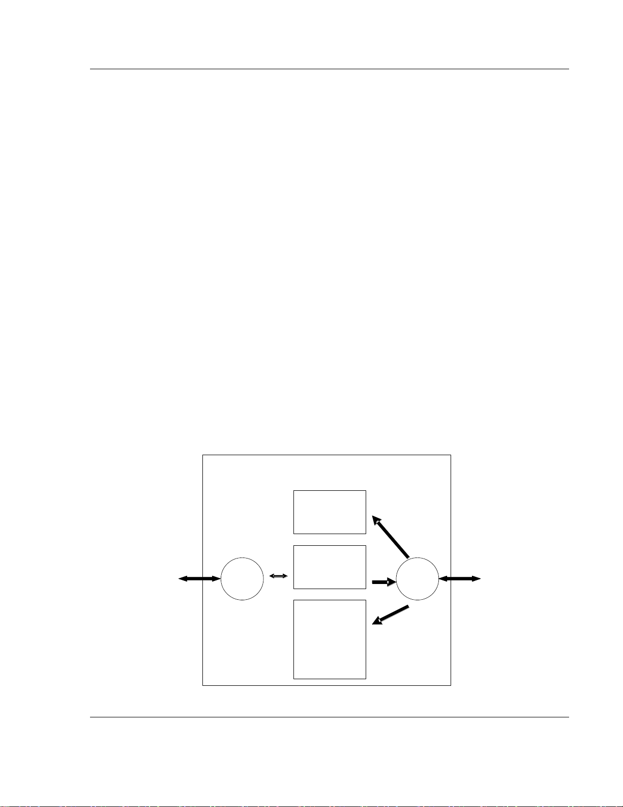
2.5 Module Internal Database
The internal database is central to the functionality of the module. This database
is shared between all the ports on the module and is used as a conduit to pass
information from one device on one network to one or more devices on another
network. This permits data from devices on one communication port/network to
be viewed and controlled by devices on another port/network. In addition to data
from the master port, status and error information generated by the module can
also be mapped into the internal database.
ProSoft Technology, Inc. Page 9 of 70
June 24, 2013
Page 10

Functional Overview PDPM ♦ ProLinx Gateway
Type
Specifications
General Parameters
Internal Database
Up to 4000 registers (words) available.
Communication parameters
Baud Rate: 9.6 kbps to 12 Mbps
PROFIBUS Master
Command List
Read Diag
Global Cmd
Read Cntrs
Reset Cntrs
Status Data
Error codes available on an individual command
basis. In addition, a slave status list is maintained
per active PROFIBUS Master port.
PROFIBUS Master
Node address
0 to 125 (software selectable)
Status Data
Error codes, counters and port status available per
configured slave on the network.
Virtual
Database
Command
List
Other
Driver
PROFIBUS
Driver
Slave
Device
Databases
Other
Protocol
PROFIBUS
Master
PROFIBUS
Slaves
Request
Response
Read
Read for
Write Command
Write for Read
Command
Write
Read
Protocol Manual PROFIBUS DP Master
2.5.1 PROFIBUS Master Port Specifications
2.5.2 PROFIBUS Master Port Access to Database
The Master driver uses the database in two ways:
1 A read command issued to a slave device by the master driver will return the
slave data into the internal database.
2 A write command issued to a slave device by the master driver uses the data
in the internal database to write to the slave device.
Page 10 of 70 ProSoft Technology, Inc.
June 24, 2013
Page 11
PDPM ♦ ProLinx Gateway Functional Overview
ACTIVE
ERR
Port 0
ACTIVE
ERR
Debug
ACTIVE
ERR
Port 0
Config
TKN
ERR RUN
RDY
Profibus Master
PROFIBUS DP Master Protocol Manual
In addition to data from the master port, status and error information generated
by the module can also be mapped into the internal database.
2.6 Master/Slave Communication Phases
The communication between the Master and the slaves takes place in the
following phases:
Parameterization and configuration phase
Usable data transfer phase
Before a DP slave can be integrated into the usable data transfer phase, the
parameterization and configuration phase runs a device identification test that
verifies that the planned configuration matches the actual device configuration for
each slave in the PROFIBUS network. The test verifies that:
The device is actually there
It is the right type of device
The station address set on the device matches the station address in the bus
configuration
The formats, telegram length information, and bus parameters are correct
and
The number of configured inputs and outputs is correct
2.7 Port Physical and Protocol Specifications
The ProLinx module supports the PROFIBUS Master protocol as a Master on
either a Mono-Master or Multi-Master network.
ProSoft Technology, Inc. Page 11 of 70
June 24, 2013
Page 12
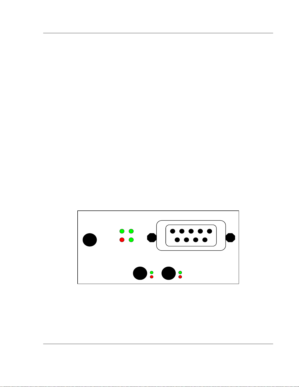
Functional Overview PDPM ♦ ProLinx Gateway
Port Label
Function
Debug
Debug/Configuration
Port 0
Communication Port 0
Config
PROFIBUS Master Configuration Port
PROFIBUS Master
PROFIBUS Master Port
Type
Specifications
Serial Ports
Serial Port Adapter Cables
One Mini DIN to DB-9M adapter cable included for
each configurable serial port
Config Port Connector/ Pinout
DB-9F connector / DTE pinout
Serial Port Isolation
2500V RMS port-to-port isolation per UL 1577.
3000V DC min. port to ground and port to logic
power isolation.
Serial Port Protection
RS-485/422 port interface lines TVS diode protected
at +/- 27V standoff voltage.
RS-232 port interface lines fault protected to +/- 36V
power on, +/- 40V power off.
Protocol Manual PROFIBUS DP Master
The relationship between the port labeling on the front of the ProLinx module and
the application is as follows:
2.7.1 Serial Port Specifications
Note: On all ProLinx modules, data from the application port on the main board, serial Port 0, is not
buffered. Packets go directly to and from the serial chipset to the processor. This has the potential
to cause the serial communications to become erratic at baud rates above 38,400 baud.
ProLinx modules with 4 serial ports have a separate serial interface board for serial Ports 1, 2, and
3. These serial ports are buffered and can handle communications up to 115,200 baud.
Page 12 of 70 ProSoft Technology, Inc.
June 24, 2013
Page 13

PDPM ♦ ProLinx Gateway Configuration
In This Chapter
Using the ProLinx SyCon PROFIBUS Configurator .............................. 13
PROFIBUS DP Master Protocol Manual
3 Configuration
3.1 Using the ProLinx SyCon PROFIBUS Configurator
The ProLinx SyCon PROFIBUS is a PROFIBUS-DP configurator that provides an
automatic means of configuring a PROFIBUS Master Module. All devices are
configured using a single tool which checks dependencies between devices and
thereby only allows configurations that make sense.
In addition, ProLinx SyCon documents the fieldbus system. Detailed
configuration documentation may be printed out that includes details between the
bus topology and the utmost detail of a single device. ProLinx SyCon supports
standardized files that contain information about all features and limitations of the
slave device and uses these files for configuration.
Lastly, the ProLinx SyCon is equipped with a diagnostic mode that allows viewing
of fieldbus status information.
3.1.1 Install ProLinx Sycon Configurator
PROLINX SyCon requires:
A DVDdrive
486 or better CPU
20Mb of free hard disk space
Minimum 16 Mb RAM
Serial (RS232) Communication Port (COM1, COM2, COM3 or COM4)
A screen and graphics card capable of 800x600 resolution
Windows 95, Windows 98, Win NT4 with Service Pack 3 or higher
For Windows 95, minimum Service Pack 1
For Windows NT 4.0, minimum Service Pack 3
3.1.2 Installation
Close all active applications before starting the installation program and perform
the following:
1 Start the installation by running \ProLinx\Utilities\Sycon\SyCon\Setup.exe
from the installation DVD.
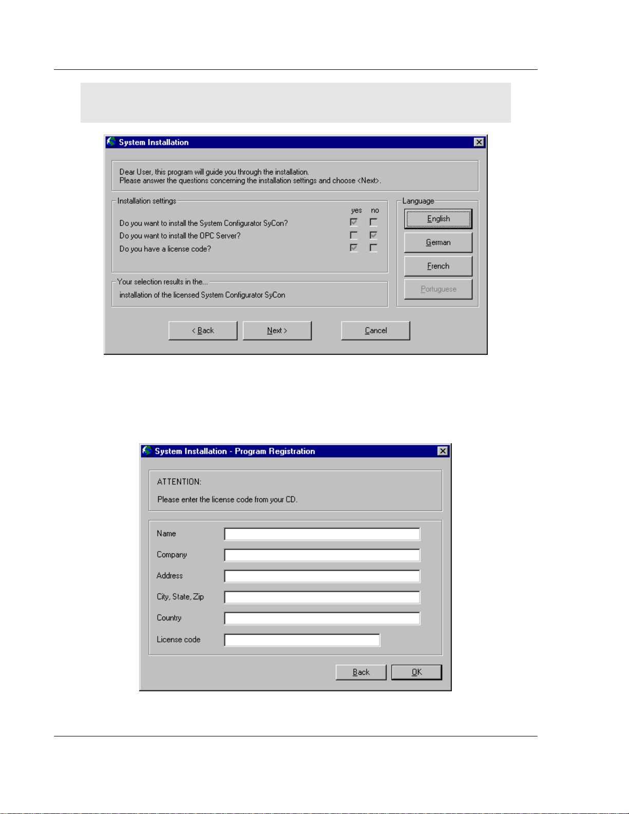
2 As the setup program runs, the program prompts you to make selections as
to what components to install.
3 Select the appropriate components based on the following example.
ProSoft Technology, Inc. Page 13 of 70
June 24, 2013
Page 14
Configuration PDPM ♦ ProLinx Gateway
Protocol Manual PROFIBUS DP Master
Note: ProLinx SyCon does not use the OPC server and a license number must be entered in order
to complete the installation.
4 Enter the license code and company information when prompted. You will
find the license code in E:\ProLinx\Utilities\Sycon\SyCon\LIC_044.TXT
(double-click the filename to open in Notepad.exe)
Page 14 of 70 ProSoft Technology, Inc.
June 24, 2013
Page 15
PDPM ♦ ProLinx Gateway Configuration
PROFIBUS DP Master Protocol Manual
The System Installation program automatically launches the PROLINX SyCon
installation program. When prompted for components to install, choose
Configurator and CIF Device Driver.
GSD Files
Each PROFIBUS-DP manufacturer uses standard device description files to
define the PROFIBUS-DP device functionalities on the network. These definitions
are called GSD files. The set of device description files (GSD files) build the
device database.
PROLINX Devices
The GSD files for PROLINX devices are located on the ProLinx Solutions DVDin
the \ProLinx\Utilities\PDPS_GSD folder.
Refer to E:\ProLinx\Utilities\PDPS_GSD\ProLinx_PDPS\readme.pdf to determine
the correct GSD files to use.
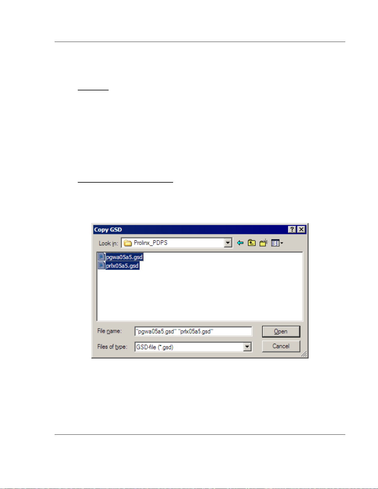
To import the ProLinx GSD files:
1 In SyCon, open the File menu, and choose Copy GSD.
2 In the Copy GSD dialog box, navigate to your DVDdrive, and select the path
\ProLinx\Utilities\PDPS_GSD.
3 Press [Ctrl][A] to select all the GSD files in that folder, and then click Open.
4 You will be prompted to import the BMP files that accompany the GSD files.
Click Open to import each of the selected BMP files.
Other Devices
For other devices, these files should be provided and updated by the device
manufacturer.
ProSoft Technology, Inc. Page 15 of 70
June 24, 2013
Page 16
Configuration PDPM ♦ ProLinx Gateway
Protocol Manual PROFIBUS DP Master
You can also get the GSD files from the homepage of the PROFIBUS user
association:
http://www.PROFIBUS.com (http://www.profibus.com)
For all available configurations, GSD files must be contained in the directory
GSD. During installation of the program PROLINX SyCon, the available files will
be included. If you need another GSD file during PROLINX SyCon runtime you
have to copy this file with the menu item File - Copy GSD.
The GSD directory path is changeable. To modify it from the default to another
path use the menu Settings - Path.
All GSD files have to be present in this directory. The default path for ProLinx
SyCon GSD files is
C:\Program Files\HMS\SyCon\Fieldbus\PROFIBUS\GSD
At program startup, PROLINX SyCon automatically reads in all GSD files that are
present in the GSD directory. Because of this, device names are placed in an
internal list. The device-specific data is taken online directly from the GSD file
during the configuration phase.
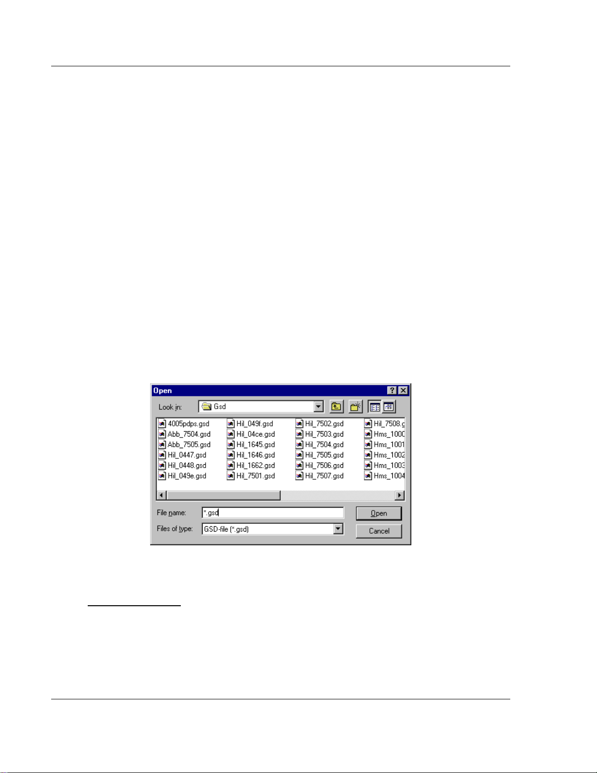
If you must use a GSD file that is not included in the selection list during the
configuration phase, you have to copy the file to the GSD using the File - Copy
GSD command. If you use this option or manually copy a file to the directory
using Windows Explorer, you must activate the Reread command using the
menu Settings - Path and OK acknowledgement.
In the menu Tools - GSD Viewer all GSD files of the directory are shown.
3.1.3 Configuring a PROFIBUS Using PROLINX SyCon
Basic Configuration
ProLinx SyCon configures the PROFIBUS system quickly and easily.
Perform the following procedure to configure the PROFIBUS system.
1 Select File - New from the menu.
2 ProLinx SyCon will start the configuration mode and open the window with
the bus line.
Page 16 of 70 ProSoft Technology, Inc.
June 24, 2013
Page 17
PDPM ♦ ProLinx Gateway Configuration
PROFIBUS DP Master Protocol Manual
3 Insert the master you are defining on the bus.
4 Insert DP slaves and assign them to the master.
5 Configure these DP slaves with the actual I/O modules, parameter data, and
so on. Ensure that the right addressing mode has been selected.
6 If using a multi-master network, look at the dependencies/connections
between the devices by selecting one master after the other as actual master
to check your configuration.
7 Select the baud rate and bus parameters.
8 Set up the device assignment that defines how ProLinx SyCon is to
communicate with the devices.
9 Save the configuration.
10 Select the port to be configured and perform the download process to all
devices.
11 Connect the PROFIBUS cable to the device.
12 Start the debug mode to check the communication.
13 Print out the documentation produced by the PROFIBUS system. If
PROFIBUS is running, start with the installation of the application.
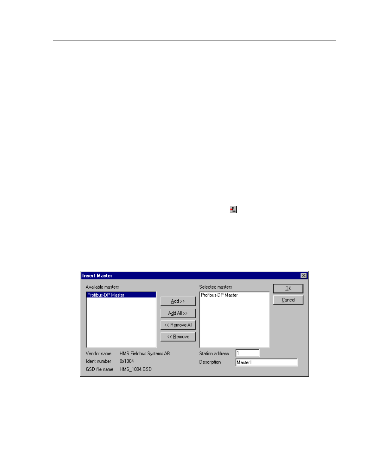
3.1.4 Inserting a Master
To insert a master in the configuration, select the Insert - Master menu to open
the selection dialog box or click the following button:
The mouse cursor changes automatically to the insert master cursor. Click on the
position where you want to insert the new master. A dialog box appears where
you can select one or more masters. You can select different master types
(depending on the vendor brand).
If you chose the ProLinx PROFIBUS Master, the Vendor information is displayed
exactly as shown in the following example:
In this example, a PROFIBUS-DP Master will be added with Station Address 1
and the Description Master 1.
ProSoft Technology, Inc. Page 17 of 70
June 24, 2013
Page 18
Configuration PDPM ♦ ProLinx Gateway
Protocol Manual PROFIBUS DP Master
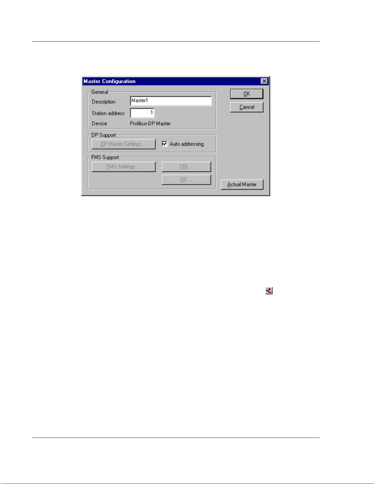
3.1.5 Master Configuration
Double-click the master to configure it. The following dialog box appears.
This configuration window allows you to:
Specify the station address of the master
Specify a (symbolic) description for this master
Set this master as the actual master (to do a download for example)
Activate or deactivate the auto addressing
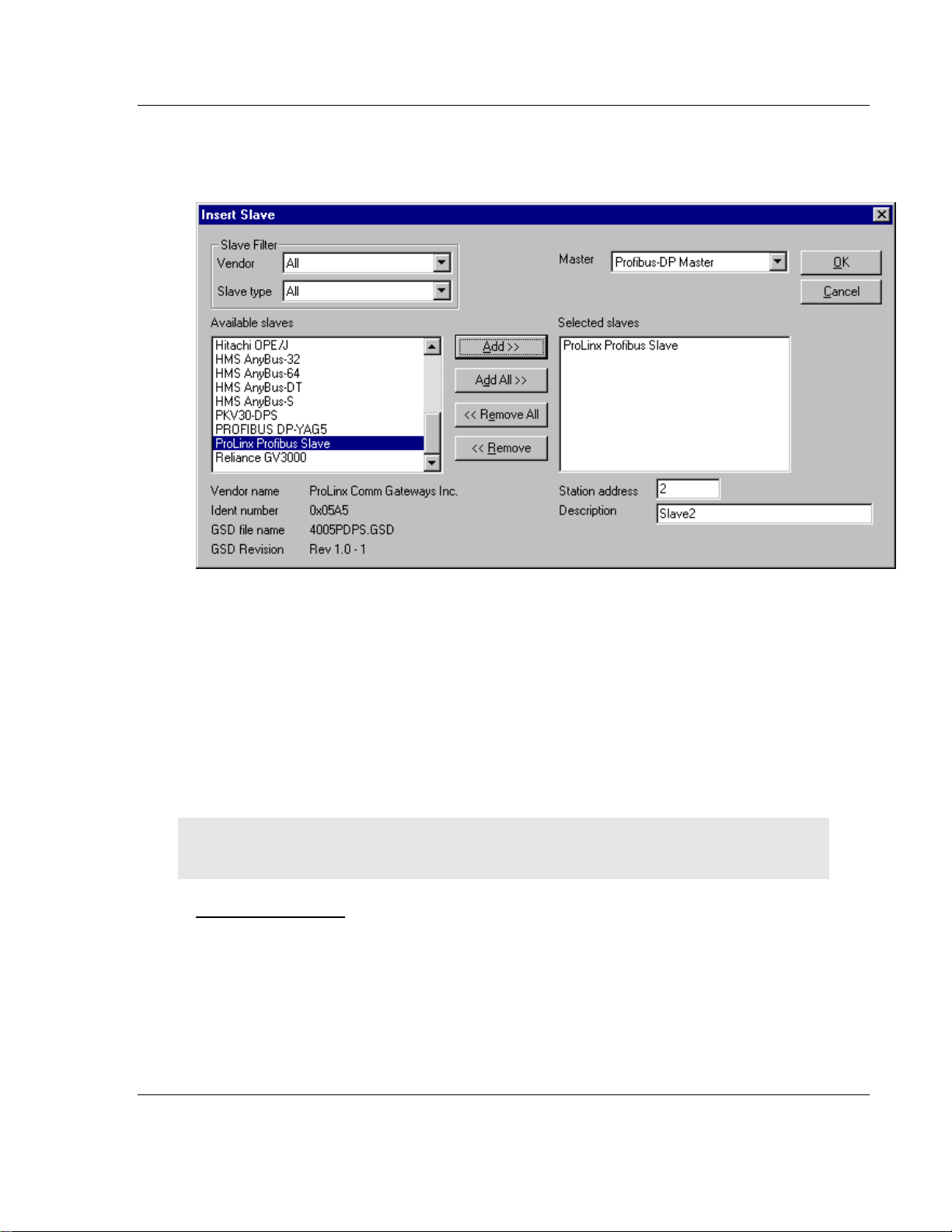
3.1.6 Inserting a Slave Device
To insert new PROFIBUS-DP slaves in the configuration, select the Insert Slave menu to open the selection window or click the following button:
Page 18 of 70 ProSoft Technology, Inc.
June 24, 2013
Page 19
PDPM ♦ ProLinx Gateway Configuration
PROFIBUS DP Master Protocol Manual
The mouse cursor changes automatically to the insert slave cursor. Click on the
position where you want to insert the new slave. A dialog box appears where you
have to select one or more slaves.
The Available slaves list-box displays all slave devices present in the GSD
directory. A filtering feature is available is you want to view by a special slave
family. If a slave is selected, information about that slave appears below the
Available slaves list box..
With a double click or with the button Add, the slave appears in the right list box.
All devices in this box will be connected to the active master displayed in the
Master window. You must select each slave one-by-one. You can also give each
a device a name or a short description in the Description Field.
The Station address field increments with each addition of a new slave. However,
this address may be overwritten.
Note: It is possible to choose one slave several times but each device must have its own station
address to distinguish them on the network.
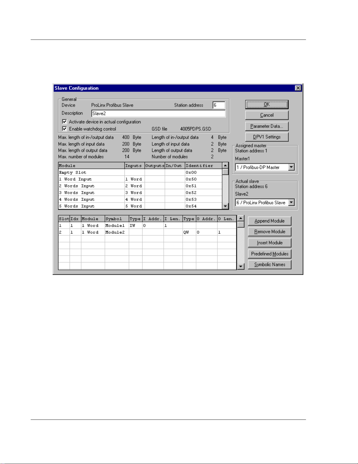
Configuring a Slave
Slave-specific configuration is accomplished using the Slave Configuration dialog
box. Here, modules and associated data are assigned to the address of the
process data image in the master device. These addresses correspond to the
application in the PLC.
Select the menu Settings - DP Slave Configuration or double-click on a slave
to open Slave Configuration dialog box.
ProSoft Technology, Inc. Page 19 of 70
June 24, 2013
Page 20
Configuration PDPM ♦ ProLinx Gateway
Protocol Manual PROFIBUS DP Master
There are two types of DP-slaves; simple and modular. A simple slave has a
fixed data length. A modular slave's data length is configurable. This type of
slave can be understood as an assembly of one or more simple slaves with one
bus address.
The upper table contains all available modules of the slave. In the case of a
simple slave, there is only one module that is automatically copied into the lower
table by ProLinx SyCon. A modular slave must be copied by the user by doubleclicking on the module or selected module in combination with the Append
Module button.
If a module has several inputs or outputs (sub modules), more lines appear in the
configuration table. These additional lines will be signed with a higher index in
the column Idx. The column Slot counts the modules.
Perform the following steps to configure the modules of the slave:
1 If not already present, select all modules from the upper table and insert them
in the lower table to be configurable.
2 The sequence of the modules in the lower list is important and must
correspond to the real physical slave configuration.
Page 20 of 70 ProSoft Technology, Inc.
June 24, 2013
Page 21
PDPM ♦ ProLinx Gateway Configuration
PROFIBUS DP Master Protocol Manual
3 Assign the addresses of the module data in the process image for each
module in the lower table. This is done in the columns Type and Address for
input and output separately.
4 The I/O address can be entered by the user or set automatically by ProLinx
SyCon. Therefore the flag Auto Addressing must be set in the window
Master Settings. If active, ProLinx SyCon will place all I/O data offsets in
physical order. This is done during the download procedure and the assigned
addresses can be checked in the Address Table. If the addresses are
entered manually the default address 0 in the field I Address respectively O
Address must be overwritten.
Note: Offset addresses are entered as a word (16-bit) address.
With the flag Watchdog Control activated it is fixed how the slave will react to
the interruption of the communication with the belonging master. Is this flag
activated and the slave recognized the interrupted communication over the
control interval, the slave will set all outputs to 0 and will set itself into the main
mode.
Caution: If Watchdog Control is switched off, possible set outputs will not be reset by the slave,
although the communication is broken.
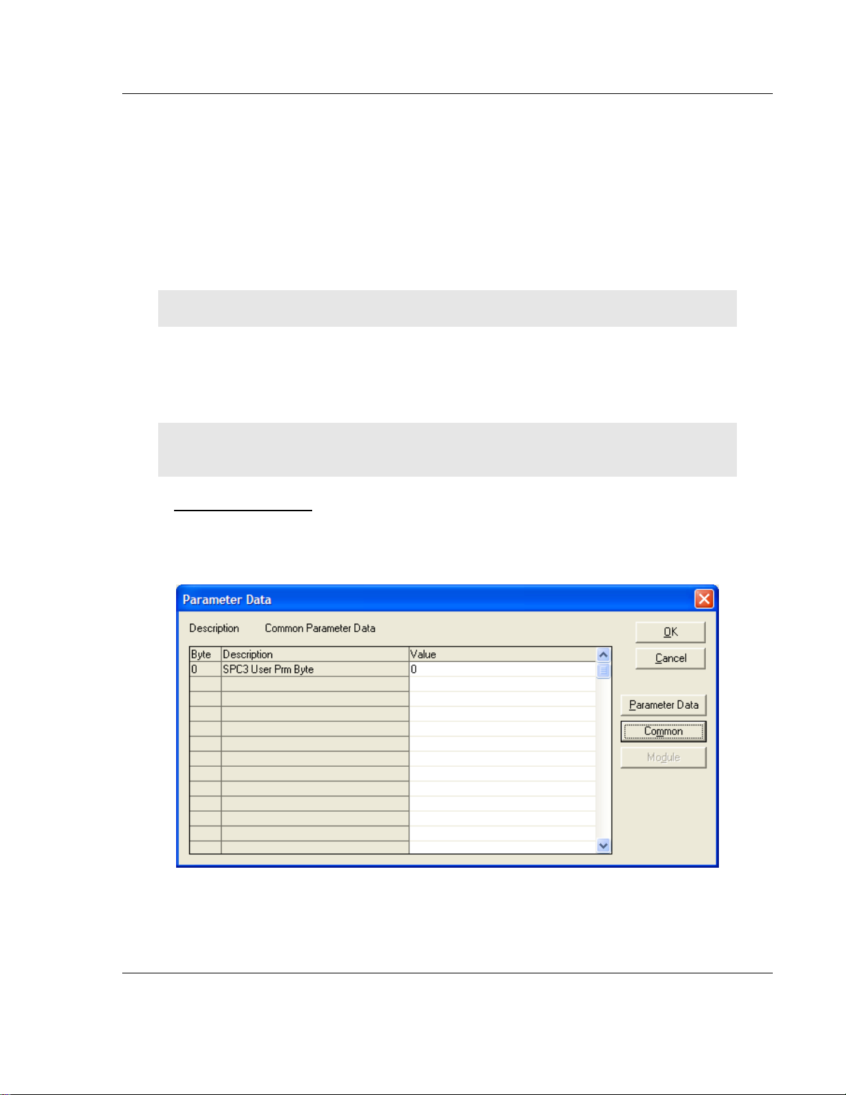
Set_Param (SAP61)
ProSoft PROFIBUS Slave (PDPS) devices have a configurable parameter for
SPC3 User Prm Byte. The following illustration shows the value of this parameter
in Sycon, the configuration tool for ProLinx PROFIBUS Master devices.
ProSoft Technology, Inc. Page 21 of 70
June 24, 2013
Page 22

Configuration PDPM ♦ ProLinx Gateway
Byte
Bit Position
Designation
7 6 5 4 3 2 1 0
0
Lock
Reg
Unio
Req
Sync
Req
Free
Req
WD
on
Res
Res
Res
Station status
1
WD_Fact_1
2
WD_Fact_2
3
MinTSDR
4
Ident_Number_High
5
Ident_Number_Low
6
Group_Ident
7
Spec_User_Prm_Byte
8 to
243
User_Prm_Data
Byte 7
Spec_User_Prm_Byte
Bit
Name
Significance
Default State
0
Dis_Startbit
The start bit monitoring in the
receiver is switched off with
this bit
Dis_Startbit = 1,
That is, start bit monitoring is
switched off.
1
Dis_Stopbit
Stop bit monitoring in the
receiver is switched off with
this bit
Dis_Stopbit = 0
That is, stop bit monitoring is not
switched off.
2
WD_Base
This bit specifies the time
base used to clock the
watchdog.
WD_Base = 0: time base 10
ms
WD_Base = 1: time base 1 ms
WD_Base = 0
That is, the time base is 10 ms.
3 to 4
Res
To be parameterized with 0
0
5
Publisher_Enable
DXB-publisher-functionality of
the SPC3 is activated with this
bit
Publisher_Enable = 0, DXBrequest-telegrams are ignored;
Publisher_Enable = 1, DXBrequest-telegramme are processed
6 to 7
Res
To be parameterized with 0
0
Protocol Manual PROFIBUS DP Master
Parameter Data Structure
SPC3 evaluates the first seven data bytes (without user prm data), or the first
eight data bytes (with user prm data). The first seven bytes are specified
according to the standard. The eighth byte is used for SPC3-specific
communications. The additional bytes are available to the application.
Page 22 of 70 ProSoft Technology, Inc.
June 24, 2013
Page 23

PDPM ♦ ProLinx Gateway Configuration
PROFIBUS DP Master Protocol Manual
3.1.7 Settings
Device Assignment
PROLINX SyCon is able to configure different devices in a PROFIBUS network.
To run the online functions of such a device, it must be defined how PROLINX
SyCon can communicate with it. This is done in the menu item Device
Assignment.
The external connection can be checked with the buttons Connect COM 1 to
Connect COM 4. PROLINX SyCon sends a request on that COM port and asks
for the firmware. If there is a Master device connected, the firmware is displayed
otherwise there will be a timeout error.
Bus Parameter
For a PROFIBUS DP system with one master, the only parameter that must be
selected is the baud rate.
ProSoft Technology, Inc. Page 23 of 70
June 24, 2013
Page 24

Configuration PDPM ♦ ProLinx Gateway
Protocol Manual PROFIBUS DP Master
The baud rate of the PROFIBUS is common for all bus devices. Changing the
baud rate has the consequence that all other parameters will be re-calculated.
The System Configurator checks if the baud rate is supported by all configured
devices on basis of the entries in the GSD file.
If the System Configurator finds at least one device in the configuration that does
not support the selected baud rate, an error message appears. Some parameters
can be changed individually by opening the Edit Bus Parameter dialog box. Use
the Edit button to look at the actual parameters.
Note that if any changes are made in the bus parameters, the parameter for the
field Optimize must be changed from standard to by user.
Caution: Changing the bus parameter individually can force a communication break.
The Highest Station Address is the highest bus address up to which the master
will search for other active master stations to pass the send permission. This
value should not be set below the master address.
DP Master Settings
The current version of PROLINX SyCon does not allow changing of DP-Master
settings. These are the default parameters:
Watchdog time: 1000 ms
Addressing mode: Word addresses
Storage formats: Big Endian
Parameter Data
User parameter data may be edited in the Parameter Data window by choosing
Settings - Parameter Data.
Page 24 of 70 ProSoft Technology, Inc.
June 24, 2013
Page 25

PDPM ♦ ProLinx Gateway Configuration
PROFIBUS DP Master Protocol Manual
If default parameters are configured in the GSD file for this slave, they are
inserted automatically when the menu is chosen the first time.
Some DP-Slave devices need some further parameterization data to change for
example, a measurement limitation or a value range. This data is slave-specific
and the functionality cannot be explained at this point.
The explanation can normally be found in the corresponding slave manual.
This following dialog box shows an example of parameter data for a slave.
A modular PROFIBUS-DP slave station may need parameter data for one or
more modules and for the slave station itself (head station). There are three
selections possible:
Hex: All parameters of the slave are shown in hexadecimal representation
Common: Parameter data of the head station
Module: Parameter data of the separate modules
ProSoft Technology, Inc. Page 25 of 70
June 24, 2013
Page 26

Configuration PDPM ♦ ProLinx Gateway
Protocol Manual PROFIBUS DP Master
After selecting the Common button, the following dialog box appears with the
common parameter data. These parameters are for the head station.
It is possible to change back into the hexadecimal description by selecting the
Hex button.
With a double click on one row of the parameter data, you are able to change the
value using the following dialog box.
Page 26 of 70 ProSoft Technology, Inc.
June 24, 2013
Page 27

PDPM ♦ ProLinx Gateway Configuration
PROFIBUS DP Master Protocol Manual
The description can also be selected by common adjustment.
If there is more than one module configured, the relevant module must be
selected first.
All parameter dialogs are taken from the GSD file. If there is no text dialog, the
input is only possible as a hex value.
Group Membership
After a master is chosen, the slaves can be assigned to 8 different groups. These
groups can be parameterized using the following dialog box.
Choose Settings, then Group Membership from the menu.
Select which group should support the DP-Freeze and DP-Sync command.
The Group Assignment button allows you to assign slaves to with the desired
characteristics.
ProSoft Technology, Inc. Page 27 of 70
June 24, 2013
Page 28

Configuration PDPM ♦ ProLinx Gateway
Protocol Manual PROFIBUS DP Master
The following table shows all configured slave devices from the main editor
window. Use this dialog box to assign slaves to selected groups.
The chosen group selection is transferred to the slaves within their startup
sequence. The group selection serves as a filter for a special DP command
called ´global control´, which can be sent as a broadcast message to selective
groups.
This command is normally used by an application program to send the output
data Sync and the input data Freeze command.
3.1.8 Project Information
Common information regarding the project can be written to the configuration
documentation by choosing Settings, then Project Information from the menu.
This information can be printed or displayed in the window.
Page 28 of 70 ProSoft Technology, Inc.
June 24, 2013
Page 29

PDPM ♦ ProLinx Gateway Configuration
PROFIBUS DP Master Protocol Manual
3.1.9 Path
To view the path of the GSD files, select Settings, then Path from the menu.
3.1.10 Language
Select Settings, then Language to display the Select Language dialog box. Use
this dialog box to specify the appropriate language for the configurator.
Select the desired language, and confirm the entry with the OK button.
A comment appears, and prompts you to restart the application to make the
changes effective. After restart, PROLINX SyCon will be uses the selected
language.
ProSoft Technology, Inc. Page 29 of 70
June 24, 2013
Page 30

Configuration PDPM ♦ ProLinx Gateway
Protocol Manual PROFIBUS DP Master
3.1.11 View the Configuration
View Device Table
Choose View, then Device Table to display the list of present devices.
Address Table
Choose View, then Address Table to display the list of addresses.
Select the master as actual master to display the address table. You can sort the
addresses by station addresses or by data addresses.
Page 30 of 70 ProSoft Technology, Inc.
June 24, 2013
Page 31

PDPM ♦ ProLinx Gateway Configuration
PROFIBUS DP Master Protocol Manual
Select the Address Overview button to display an overview about the addresses
in the input and output area.
1 The Auto Addressing mode must be inactive in order to change address
assignments.
2 Click on a cross and hold down the left mouse button. The pointer changes to
an arrow.
ProSoft Technology, Inc. Page 31 of 70
June 24, 2013
Page 32
Configuration PDPM ♦ ProLinx Gateway
Protocol Manual PROFIBUS DP Master
3 While holding down the left mouse button, move the arrow to the desired new
(still not used) position and release the mouse button.
4 The system prompts you to verify if the change should be executed.
Choose the Slave Configuration menu to select offset assignments.
Overlapped addresses are shown with a red cross (indicating that the same
address is used by more than one module.
View the slave address information by double-clicking on the corresponding
cross. The Byte Information Window opens.
Note: While the addresses are given in bytes (8-bit), a block of data can only be placed on a word
(16-bit) boundary.
3.1.12 Printing the Configuration File
Set up the appropriate printer using the Print Setup menu. Select Print to receive
a printout of the configuration.
3.1.13 Saving the Configuration
Choose Save to save the configuration if the configuration has already been
saved with a filename, otherwise, use the Save as function to assign the
configuration a filename.
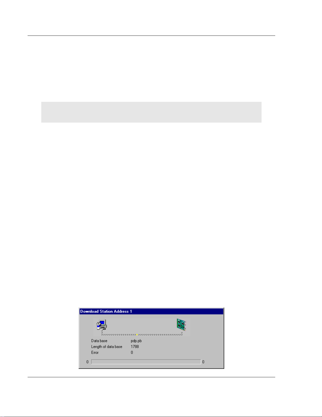
3.1.14 Downloading the Configuration
To enable the configuration and network access, the configuration must be
downloaded to the master. Choose Online, then Download from the menu. This
triggers a warning that the communication on the PROFIBUS will be interrupted.
This has to be confirmed.
Before the download is accomplished, the configurator checks the configuration.
If any error messages appear, the configuration should be checked. The most
common errors are overlapped addresses, which can be located by viewing the
Address Table overview.
If slave addressing is performed automatically, chose Auto addressing from the
Master Configuration window.
The configuration is transmitted to the selected device and stored into FLASH
memory statically. This enables it to be available after the power is switched off
and on in the device.
Page 32 of 70 ProSoft Technology, Inc.
June 24, 2013
Page 33

PDPM ♦ ProLinx Gateway Configuration
PROFIBUS DP Master Protocol Manual
After the download procedure, the device executes an internal restart and begins
with the communication if the start condition in DP Master Settings has been set
to Automatic release of the communication by the device.
3.1.15 Online Functions
Starting Debug Mode
Choose Online, then Start Debug Mode from the menu. The system configurator
cyclically interrogates the status of the network communication on the master
and individual condition of the devices. To end Debug Mode, select Online, then
Debug Mode from the menu.
The Debug Window
When the debug session is started, the Configuration Window changes to the
Debug window. The devices and the line between them are displayed in green or
red color depending on the established network communication.
When the debugger starts, PROLINX SyCon requests the status of all devices
from the master. If there is an error on a device, the bus line to this device is
drawn in red otherwise it is green.
PROLINX SyCon also displays the letters Diag if the device signals diagnostic
information. This information is displayed closer if you click with the mouse onto
the corresponding device in debug mode.
ProSoft Technology, Inc. Page 33 of 70
June 24, 2013
Page 34

Configuration PDPM ♦ ProLinx Gateway
Protocol Manual PROFIBUS DP Master
To activate Debug mode select Online, the Start Debug Mode. The menu
Online - Device Diagnostic activates the PROFIBUS device diagnostic. To end
Debug Mode, select Online, then Stop Debug Mode.
If diagnostic information is available for a specific device, the text Diag appears
next to the device icon in red. To access additional device-specific diagnostic
information, double-click on the device itself, or select the device, then select
Online - Device Diagnostic.
Page 34 of 70 ProSoft Technology, Inc.
June 24, 2013
Page 35

PDPM ♦ ProLinx Gateway Configuration
PROFIBUS DP Master Protocol Manual
Device Diagnostic
The following example shows a diagnostic dialog box.
Device Diagnostic Descriptions
Master_Lock
The slave has already been parameterized by another master and is locked.
Search for another master on the network and delete its assignment to this
slave station, or remove the other assigned master from the network to
enable communication with this slave.
Parameter_Fault
This bit is automatically set by the slave when the parameters sent by the
master contain wrong or insufficient data. On every received parameter
telegram, the slave executes a check routine on the entire parameter
telegram. If the slave detects a faulty parameter value or detects illegal data
during its check, it reports the "parameterization error". During the check
routine, the slave compares its ident_number with the ident_number sent
by the master. If the slave reports this error, compare the real ident_number
shown in the slave diagnostic field in debugger mode with the one read out of
the GSD-File. Use the View/Device Table menu to view this information.
If parameter data is configured in PROLINX SyCon, but the slave does not
support it, reduce the parameter data in PROLINX SyCon to a length of zero.
Invalid_Slave_Response
ProSoft Technology, Inc. Page 35 of 70
June 24, 2013
Page 36

Configuration PDPM ♦ ProLinx Gateway
Protocol Manual PROFIBUS DP Master
This bit is set by the master when the master receives an invalid answer from
the slave. The physical contact to the slave works, but the logical does not or
was interrupted. This may occur if a PROFIBUS-FMS slave is connected to
the DP-master. The slave does not understand the DP-Telegrams and rejects
them. It is handled as "Invalid_Slave_Response".
Not_Supported
This bit is set by the slave when a function should be performed that is not
supported. Newer releases of slave stations normally support the Sync and
Freeze Mode for I/O data. This is set in the GSD file, read by PROLINX
SyCon, and transferred to the slave in the parameter telegram. If
"Not_Supported" is reported, the GSD file declares at least one of these
commands as supported, but the slave does not. Ask the manufacturer of the
slave device for another GSD file or ask if the slave reports "Not_Supported"
on other wrong parameter data.
Extended_Diag
This bit is set by the slave if optional extended diagnostic data are a
containment of the slave diagnostic field. A slave station normally uses
extended diagnostic data if module-specific diagnostic information, for
example, exceeded analog values or low power should be reported to the
master. Click the Extended Diagnostic button to view a Hex-dump of the
reported values.
Configuration_Fault
During the PROFIBUS-DP startup procedure, the slave compares its internal
I/O configuration with the one configured in the master. If the slave detects
differences, it reports the "Cfg_Fault" error. This indicates that the master has
a different I/O module constellation for this slave configured, than the slave
device physically holds down. First compare visually all configured I/O
modules in the configuration data of PROLINX SyCon for this slave with its
real physical constellation. Note that the order of the module is important and
should also be compared. Some slaves need virtual I/O modules to be
configured first or empty slot modules to get an even number of modules to
run. This slave specific I/O module behavior can normally be read out in the
slave documentation. Last help to get the slave module constellation is to
read out its constellation by a PROFIBUS-DP command Compare
Configuration. Click on this button in the diagnostic field and get a HexDump of the real slave configuration data and the configured one (Real
Configuration and PROLINX SyCon Configuration). Note that the DPconfiguration data is coded in bit defined byte arrays to hold the I/O
information very compressed. The DP configuration is coded in a very
compact form. The code for the modules is shown in the slave
configuration.
Station_Not_Ready
When or at which event the slave sets this bit is not defined in the norm
specification. The meaning "Not_Ready" can be seen as not ready to perform
the I/O data exchange. This may indicate several slave specific reasons.
Usually the bit is set in combination with one of the other fault bits.
Station_Non_Existent
Page 36 of 70 ProSoft Technology, Inc.
June 24, 2013
Page 37

PDPM ♦ ProLinx Gateway Configuration
PROFIBUS DP Master Protocol Manual
This bit is automatically set by the master if this slave is not responding on
the bus. If this error occurs, compare the configured station address with the
physical one of the slave. Then ensure that the slave module supports the
configured baud rate. Some old modules only support bps rates up to 1.5
Mbps. Other modules must be jumpered to DP-Norm behavior first, to be
operative with a DP-Norm master. Then check your bus cable. Only the
TX/RX-pins 3<->3 and 8<->8 must be connected to get the contact between
two PROFIBUS components.
Slave_Deactivated
This bit is automatically set by the master if the slave in its parameter set is
marked as inactive, in order to be taken out of cyclic I/O processing.
Sync_Mode
This bit is set by the slave when it has received the sync control command.
Freeze_Mode
This bit is set by the slave when is has received the freeze control command.
Watchdog_ON
This bit is set by the DP-slave when its watchdog control is active to
supervise its corresponding master connection.
Static_Diag
The slave sets this bit to indicate that the master system is not operative for
I/O due to a general error. In a case of a set static diagnostic bit, the master
has to collect diagnostic information as long as this bit is active. On which
events or at what time this bit can be set by a slave device is not defined in
the norm description.
Parameter_Req_used
The slave sets this bit to force the master system to do a new
parameterization. This bit is set as long as new parameterization must be
performed.
Ext_Diag_Overflow
This bit is set if there is more extended diagnostic information to report to the
master than can be given to the master in one DP-diagnostic telegram. The
DP-slave sets this bit, for example, if there is more diagnostic channel
information than the slave can hold down in its diagnostic buffer.
Assigned_Master_Address
In this octet, the address of the DP-master that has done the
parameterization of the slave is entered. If the DP-slave is not parameterized
from any DP-master, the DP-slave puts the address 255 dec here.
Real_Ident_Number
With the Ident_Number, the slave reports its own unchangeable identification
number that was assigned by the PROFIBUS user organization. This
identification code can serve in PROLINX SyCon to compare it with the Ident
code of the GSD file of the configured slave if a parameterization error is
reported.
ProSoft Technology, Inc. Page 37 of 70
June 24, 2013
Page 38

Configuration PDPM ♦ ProLinx Gateway
Protocol Manual PROFIBUS DP Master
Firmware Download
If you want to make a Firmware download, select Online, then Firmware
Download from the menu. The Open window appears. Select the new Firmware
and confirm your entry with the Open button.
Firmware / Reset
Choose Online, then Firmware Reset from the menu to display the name and
version of the firmware of the selected device. The Reset button resets the
device.
Extended Device Diagnostic
The menu item, Online - Extended Device Diagnostic helps to detect possible
bus and configuration faults while trying to get the bus fully operative. When the
normal debugger does not supply any helpful information, use this option to
obtain fault localization information. This menu activates a list of available
structures. The listed structures can be displayed to show the values.
Several task states are available.
Note: All items in this list do not work for this master.
Page 38 of 70 ProSoft Technology, Inc.
June 24, 2013
Page 39

PDPM ♦ ProLinx Gateway Configuration
PROFIBUS DP Master Protocol Manual
Global State Field
Select the menu Online - Global State Field to see information about the global
state field. The first row shows the Online master main state for example,
OPERATE, STOP. The next row shows the collective status bits. An activated bit
is red. Further contents are given:
Collective online error location and corresponding error
Statistic bus information
Device specific status bits: Parameterized Devices, Activated Devices and
Devices with Diagnostic are shown if you click on that button. The activated
addresses are white numbers.
This application updates the status online in the global state field. You can see
the diagnostic by double-clicking at a selected station address of a device. The
meaning of the shortcuts is listed below:
Collective Status Bits
TOUT (TIMEOUT-ERROR) The device has detected an overstepped timeout
supervision time because of rejected PROFIBUS telegrams. This is an
indication for bus short circuits while the master interrupts the
communication. The number of detected timeouts is fixed in the statistic bus
information variable. The bit will be set when the first timeout was detected
and will not be deleted.
ProSoft Technology, Inc. Page 39 of 70
June 24, 2013
Page 40

Configuration PDPM ♦ ProLinx Gateway
Protocol Manual PROFIBUS DP Master
NRDY (HOST-NOT-READY-NOTIFICATION) Indicates if the host program
has set its state to operative or not. If this bit is set the host program is not
ready to communicate.
EVE (EVENT-ERROR) The device has detected bus short circuits. The
number of detected events is fixed in the statistic bus information variable.
The bit will be set when the first event was detected and will not be deleted
any more.
FAT (FATAL-ERROR) Because of a heavy bus error, no further bus
communication is possible.
NEXC (NON-EXCHANGE-ERROR) At least one slave has not reached the
data exchange state and no process data exchange is possible with it.
ACLR (AUTO-CLEAR-ERROR) Device stopped the communication to all
slaves and reached the auto-clear end state.
CTRL (CONTROL-ERROR) Parameterization error.
Live List
If the menu Online - Live List is selected, an overall view of all active devices on
your PROFIBUS network is shown. A green number (the number is the station
address) for the master and a blue number for the slave is norm. The status of
the live list is not automatically updated online.
Click on the Update button after you change your inputs to update this window.
Page 40 of 70 ProSoft Technology, Inc.
June 24, 2013
Page 41

PDPM ♦ ProLinx Gateway Configuration
PROFIBUS DP Master Protocol Manual
If you click on a colored station address you are given the Device type and
Device state.
I/O Monitor
This is a simple tool used to display and enter only the first 32 bytes of the
process image.
Note: The I/O monitor cannot be used with the ProLinx PROFIBUS Master unit.
ProSoft Technology, Inc. Page 41 of 70
June 24, 2013
Page 42

Configuration PDPM ♦ ProLinx Gateway
Protocol Manual PROFIBUS DP Master
Set Slave Address
Select the Online - Set Slave Address menu to change a slave address.
Write the new address in the row New Station Address. If no further changes
shall be allowed, select the field No additional changing. If necessary, add
additional parameters in hex in the field Slave parameter.
Activate the command with the Set Address button.
Start/Stop Communication
Manually start or stop the communication between masters and slaves by
selecting menu Online - Start Communication and Stop Communication
respectively.
Device Info
Select the menu Online - Device Info to see information about the selected
hardware in the configuration.
Page 42 of 70 ProSoft Technology, Inc.
June 24, 2013
Page 43

PDPM ♦ ProLinx Gateway PDPM Protocol Configuration
In This Chapter
[PROFIBUS Master] .............................................................................. 43
[PROFIBUS Master Commands] ........................................................... 45
PROFIBUS DP Master Protocol Manual
4 PDPM Protocol Configuration
The following is excerpted from a configuration file showing typical examples of
the PROFIBUS Master Port and PROFIBUS Master Command sections of a
CFG file for a PDPM port. Shipped with each unit (or available from the web) is a
default configuration file that can easily form the basis for a working solution. This
file can either be downloaded from the ProSoft web site at
www.prosoft-technology.com, or transferred from the module.
# This is the data area for setting the Profibus Master parameters
[Profibus Master]
Swap Input Bytes : No #Swap bytes in input image (yes or no)
Swap Output Bytes : No #Swap bytes in output image (yes or no)
Comm Failure Mode : 1 #0=x-fer on comm fail, 1=no x-fer on fail
Watchdog Register : 1000 #DB register to monitor for change (1=watchdog not used)
Watchdog Timeout : 50 #.1 second intervals for watchdog timeout
Watchdog Reset Value : 255 #Value to set Profibus outputs to on timeout
condition
# This section contains the Profibus Master commands to be processed by the
# module.
[Profibus Master Commands]
# Database Register Poll Command Data
# Enabled Address Count Interval Node Code Length
START
1 600 10 0 3 66 32
1 610 7 0 4 66 32
2 620 0 10 3 254 2
2 0 0 1200 0 254 0
END
4.1 [PROFIBUS Master]
# This is the data area for setting the Profibus Master parameters
[Profibus Master]
Swap Input Bytes : No #Swap bytes in input image (yes or no)
Swap Output Bytes : No #Swap bytes in output image (yes or no)
Comm Failure Mode : 1 #0=x-fer on comm fail, 1=no x-fer on fail
Watchdog Register : 1000 #DB register to monitor for change
ProSoft Technology, Inc. Page 43 of 70
June 24, 2013
Page 44

PDPM Protocol Configuration PDPM ♦ ProLinx Gateway
Protocol Manual PROFIBUS DP Master
#(-1=watchdog not used)
Watchdog Timeout : 50 #.1 second intervals for watchdog timeout
Watchdog Reset Value : 255 #Value to set Profibus outputs to on
#timeout condition
4.1.1 Swap Input Bytes
Yes or No
This parameter specifies if the data in the input data area of the module is to be
byte swapped. If the order of the bytes in the words stored in the database is not
correct, use this option. A value of Yes causes the module’s program to swap the
bytes in each word. A value of No indicates no byte swapping will occur.
4.1.2 Swap Output Bytes
Yes or No
This parameter specifies if the data in the output data area of the module is to be
byte swapped. If the order of the bytes in the words stored in the database is not
correct, use this option. A value of Yes causes the module’s program to swap the
bytes in each word. A value of No indicates no byte swapping will occur.
4.1.3 Comm Failure Mode
0 or 1
This parameter sets the data transfer mode of the module's PROFIBUS input
image to the internal database when a communication failure on the PROFIBUS
interface is detected. If the parameter is set to 0, the input image will continue to
be transferred. If the parameter is set to 1, the input image will not be transferred
and the last values will be retained.
4.1.4 Watchdog Parameters
Watchdog Register : 1000 #DB register to monitor for change
#(-1=watchdog not used)
Watchdog Timeout : 50 #.1 second intervals for watchdog timeout
Watchdog Reset Value : 255 #Value to set Profibus outputs to on
#timeout condition
The watchdog functionality allows the module to set the PROFIBUS output
registers to a pre-defined value once a communication failure occurs. The
watchdog is implemented through the monitoring of a specific database register
(configured through the Watchdog Register parameter). The remote node should
write a new value to this database register faster than the timeout period
(configured through the Watchdog Timeout parameter). If this time period
elapses but no change is detected then the module will force all PROFIBUS
output registers to a specific value (configured through the Watchdog Reset
Value parameter).
In order to disable this functionality set the Watchdog Register to -1.
Page 44 of 70 ProSoft Technology, Inc.
June 24, 2013
Page 45

PDPM ♦ ProLinx Gateway PDPM Protocol Configuration
Column #
1
2
3
4
5
6
7
Function Type
Enabled
Database
Address
Register
Count
Polling
Interval
Node
Address
Command
Code
Data Length
Read Diag
1 or 2
0 to 3999
1 to 122
0 to 65535
0 to126
66
32 or 106
Global Cmd
1 or 2
0 to 3999
0
0 to 65535
0 to126
70
Group
Read Cntrs
1 or 2
0 to 3997
0
0 to 65535
0 to126
254
1 to 40
Reset Cntrs
1 or 2
0 0 0 to 65535
0
254
0
PROFIBUS DP Master Protocol Manual
4.2 [PROFIBUS Master Commands]
The [PROFIBUS MASTER COMMANDS] section of the CFG file sets the
PROFIBUS master port command list. This list polls slave devices attached to a
master port. The module supports three commands. This permits the module to
interface with a wide variety of PROFIBUS slave devices.
The command list is formatted differently than the other sections of the
configuration file. Commands are present in a block between the labels START
and END. These labels inform the program where the list resides. The module's
program will parse all commands after the START label until it reaches the END
label or until the command count entered for the port is reached.
The format of each command in the list is the same with the content dependent
on the operation to perform. The following table describes the format and list of
PROFIBUS Master functions supported:
Command list example:
[PROFIBUS Master Commands]
# Database Register Poll Command Data
# Enabled Address Count Interval Node Code Length
START
1 600 10 0 3 66 32
1 610 7 0 4 66 32
2 620 0 10 3 254 2
2 0 0 1200 0 254 0
END
4.2.1 66 - Read Diag
Execute a station diagnostic command to the specified node placing the
response message at the Database Address specified but only using the number
of registers entered in the Register Count field.
4.2.2 70 - Global Cmd
Execute global command using the value at the specified Database Address to
the Node Address. The Data Length field specifies the Group Select parameter.
ProSoft Technology, Inc. Page 45 of 70
June 24, 2013
Page 46

PDPM Protocol Configuration PDPM ♦ ProLinx Gateway
Bit
Definition
0
Reserved
1
Clear output data
2
Unfreeze input data
3
Freeze input data
4
Neutralize the sync command
5
Freeze output data until sync command is neutralized
6
Reserved
7
Reserved
Bit 2 or 4
Bit 3 or 5
Definition
0 0 No function
0 1 Function will be activated (that is, Freeze input data)
1 0 Function will be inactivated (that is, Unfreeze input data)
1 1 Function will be inactivated (that is, Unfreeze input data)
Protocol Manual PROFIBUS DP Master
4.2.3 254 - Read Cntrs
If the Data Length parameter is set to zero, the command will reset the counters
for all slaves. If the Data Length is specified, it represents the number of slaves
to read the static counter data. The Node Address specifies the first slave node
to consider in the request. The counter data returned is placed at the Database
Address in the command.
4.2.4 Command 70 Control Byte
The Freeze and Sync commands are used for synchronization purposes. The
Freeze command causes a slave to freeze its inputs and the Sync command
causes a slave to hold the outputs.
Page 46 of 70 ProSoft Technology, Inc.
June 24, 2013
Page 47

PDPM ♦ ProLinx Gateway Diagnostics and Troubleshooting
In This Chapter
LED Indicators ....................................................................................... 47
PROFIBUS Master Error and Status Data............................................. 48
PROFIBUS Master: Error and Status Data............................................ 48
Error Numbers ....................................................................................... 51
TKN
ERR RUN
RDY
LED
Color
Description
TKN - Token
Green On
PROFIBUS Master owns token.
PROFIBUS DP Master Protocol Manual
5 Diagnostics and Troubleshooting
The module provides information on diagnostics and troubleshooting in the
following forms:
LED status indicators on the front of the module provide general information
on the module's status.
You can view status data contained in the module through the
Configuration/Debug port or the Ethernet port, using the troubleshooting and
diagnostic capabilities of ProSoft Configuration Builder (PCB).
You can transfer status data values from the module to processor memory
and can monitor them in the processor manually or by customer-created
logic. For details on Status Data values, see Status Data Table.
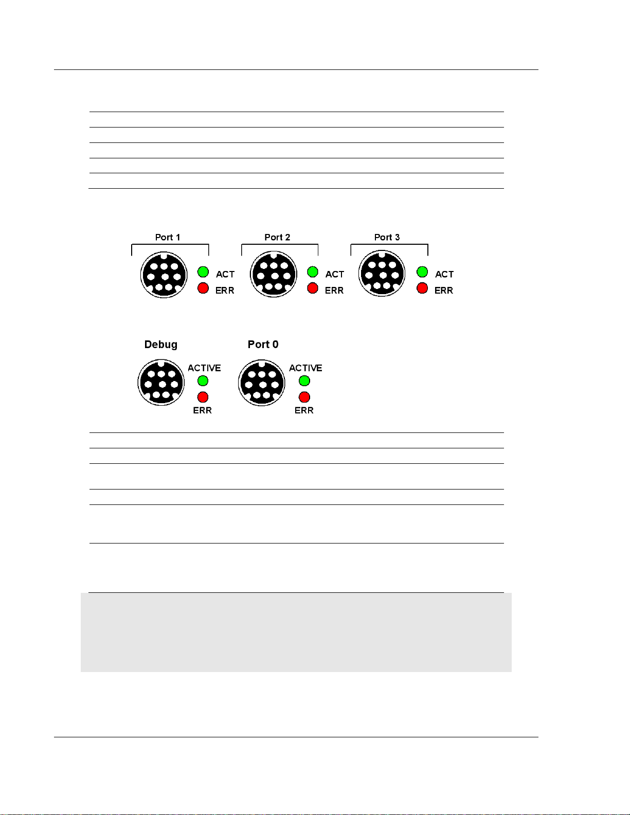
5.1 LED Indicators
Troubleshooting the operation of the PROFIBUS Master ports can be performed
using several methods.
The first and quickest is to scan the LEDs on the module to determine the
existence and possible cause of a problem. This section provides insight into the
operation of the PROFIBUS Master Port status LEDs. Information on the
module’s other LEDs can be found in the ProLinx Reference Guide.
5.1.1 LEDs for the PROFIBUS Master Port
ProSoft Technology, Inc. Page 47 of 70
June 24, 2013
Page 48

Diagnostics and Troubleshooting PDPM ♦ ProLinx Gateway
LED
Color
Description
RDY - Ready
Off
Hardware error.
Green On
Module OK.
Green cyclic flash, approx.
1 Hz.
Flash only contains boot loader, no valid
firmware stored in flash.
Green cyclic flash, approx.
4 Hz.
Hardware or system error or
firmware/configuration database download in
progress.
ERR - Error
Red Off
No errors detected.
Red On
Error on communication line. Shows if a bus
error has occurred, for example, a remote node
was not found.
RUN - Run
Green On
Communication running.
Green cyclic flash, approx.
4 Hz.
Ready for communication.
Green acyclic flash
Configuration error or fatal error.
Protocol Manual PROFIBUS DP Master
5.2 PROFIBUS Master Error and Status Data
The second and most thorough troubleshooting method for debugging the
operation of the PDPM driver (and the module in general) is the powerful Debug
port on the module which provides much more complete access to the internal
operation and status of the module. Accessing the Debug capabilities of the
module is accomplished easily by connecting a PC to the Debug port and loading
a terminal program such as ProSoft Configuration Builder or HyperTerminal.
5.2.1 Viewing Error and Status Data
The following topics list the register addresses that contain error and status data.
Use the Database View option from the ProLinx Main Menu to view the contents
of each register. The ProLinx Reference Guide provides the information on using
this option.
5.3 PROFIBUS Master: Error and Status Data
The PROFIBUS Master Error and Status Data register areas are discussed in
this section.
The data area is initialized with zeros whenever the module is initialized. This
occurs during a cold-start (power-on), reset (reset push-button pressed) or a
warm-boot operation (commanded or loading of new configuration). The format
of this data area is displayed below:
Page 48 of 70 ProSoft Technology, Inc.
June 24, 2013
Page 49

PDPM ♦ ProLinx Gateway Diagnostics and Troubleshooting
Database Address
Offset
Description
10400
0
State
Code Definition
-1 Master not in run or ready mode (restarting)
0 Waiting for initialization
1 Initialized and ready to run or running
10401
1
Mailbox State
10402
2
Scan Counter
10403
3
Mailbox Data Move Counter
10404
4
Mailbox Messages Received Counter
10405
5
Mailbox Message Error Count
10406
6
Global Command Counter
10407
7
Slave Diagnostic Request Counter
10408
8
Slave Counter Request Counter
10409
9
No Valid Data
…
…
10499
Byte
Description
0
Station status 1
1
Station status 2
2
Station status 3
3
Master address
4
Ident number high
5
Ident number low
PROFIBUS DP Master Protocol Manual
5.3.1 General Status
5.3.2 Command Status
Command list errors are located in registers 10500 through 10699.
5.3.3 Standard PROFIBUS Slave Diagnostic Bytes
The diagnostic information consists of 6 bytes of standard diagnostic information
plus any user-related diagnostic information. The standard information is shown
in the tables below.
5.3.4 Byte 0 - Station Status 1 Bits
ProSoft Technology, Inc. Page 49 of 70
June 24, 2013
Page 50

Diagnostics and Troubleshooting PDPM ♦ ProLinx Gateway
Bit
Description
0
Station not existent
1
Station not ready
2
Configuration fault
3
Extended diagnostic data present
4
Not supported
5
Invalid slave response
6
Parameter fault
7
Master lock
Bit
Description
0
Parameter request
1
Static diagnostic
2
Slave device
3
Watchdog on
4
Freeze mode
5
Sync mode
6
Reserved
7
Slave deactivated
Bit
Description
0
Reserved
1
Reserved
2
Reserved
3
Reserved
4
Reserved
5
Reserved
6
Reserved
7
Extended diagnostic overflow
Protocol Manual PROFIBUS DP Master
5.3.5 Byte 1 - Station Status 2 Bits
5.3.6 Byte 2 - Station Status 3 Bits
Page 50 of 70 ProSoft Technology, Inc.
June 24, 2013
Page 51

PDPM ♦ ProLinx Gateway Diagnostics and Troubleshooting
Error
Description
0
No error
14
OS module, firmware download
50
RAM check not OK
53
FLASH PROM checksum not OK
100 to 107
Internal system error
200
Unknown interrupt received
201
Internal watchdog expired
202
Unexpected transmit interrupt from serial channel
203
Unexpected receive interrupt from serial channel
252
Firmware download or database download active
253
Bootstrap loader active, firmware not running
Error
Number
Description
-20
DRIVER: No COM handle found
-21
DRIVER: COM port already opened
-22
DRIVER: Function call into driver failed
-23
DRIVER: Internal driver error
-24
DRIVER: Could not create read thread
-25
DRIVER: Could not create read event
PROFIBUS DP Master Protocol Manual
5.3.7 Byte 3 - Master Address
This byte shows the address of the assigned PROFIBUS Master after
parameterization. If there is an error during the parameterization process, this
byte will display the value FF (hexadecimal).
5.3.8 Byte 4 - Ident Number High
This byte shows the high byte of the specific Ident Number assigned to the
module by the PROFIBUS User Organization.
5.3.9 Byte 5 - Ident Number Low
This byte shows the low byte of the specific Ident Number assigned to the
module by the PROFIBUS User Organization.
5.3.10 Device Error Listing
5.4 Error Numbers
5.4.1 Serial Driver Error Numbers (-20 … -71)
This is the list of error numbers using the serial driver associated with the
PROFIBUS Master Configuration Port.
ProSoft Technology, Inc. Page 51 of 70
June 24, 2013
Page 52

Diagnostics and Troubleshooting PDPM ♦ ProLinx Gateway
Error
Number
Description
-26
DRIVER: Could not create write event
-27
DRIVER: Could not create timer event
-28
DRIVER: Error by writing data
-29
DRIVER: Wrong COM state
-30
DRIVER: Set COM state error
-31
DRIVER: COM buffer setup failed
-32
DRIVER: COM set timeout failed
-33
DRIVER: RX buffer overrun
-34
DRIVER: RX buffer full
-35
DRIVER: TX busy
-36
DRIVER: Error during close driver
-40
USER: COM port not opened
-41
USER: Invalid handle value
-42
USER: Invalid COM number
-43
USER: Size parameter invalid
-44
USER: Size parameter zero
-45
USER: Buffer pointer is NULL
-46
USER: Buffer too short
-47
USER: Setup error
-50
USER: Send message, timeout error
-51
USER: Could not send a message
-52
USER: Send message, no device connected
-53
USER: Error by send message, message receiving
-54
USER: Telegram collision
-55
USER: Telegram, no acknowledgement received
-56
USER: Telegram, noise
-57
USER: Telegram, data overrun
-58
USER: Telegram, parity error
-59
USER: Telegram, framing error
-60
USER: Telegram, unknown error
-70
USER: Timeout by receive a message
-71
USER: No message received
Protocol Manual PROFIBUS DP Master
5.4.2 RCS Error Numbers (4 to 93)
This is the list of error numbers returned by the RCS (Real-time Communication
System), that is the operating system. The error number is returned in an answer
message. Command messages and answer messages communicate between
the application (for example, the system configuration) and the master device.
An example of this communication is the download of a configuration.
Page 52 of 70 ProSoft Technology, Inc.
June 24, 2013
Page 53

PDPM ♦ ProLinx Gateway Diagnostics and Troubleshooting
Error
Number
Description
0
No error
4
Task does not exist
5
Task is not initialized
6
The MCL is locked
7
The MCL rejects a send command because of an error
20
Database not configured
21
Data base segment not configured or not existent
22
Number for message wrong during download
23
Received number of data during download does not match to that in the command
message
24
Sequence identifier wrong during download
25
Checksum after download and checksum in command message does not match
26
Write/Read access of data base segment
27
Download/Upload or erase of configured data base type is not allowed
28
The state of the data base segment indicated an error. Upload not possible
29
The access to the database segment needs the bootstrap loader. The bootstrap
loader is not present
30
Trace buffer overflow
31
Entry into trace buffer too long
37
No or wrong license. The OEM license of the system configuration allows only
communication to devices that have the same license inside
38
The database created by the system configuration and the database expected by the
firmware is not compatible
39
DBM module missing
40
No command free
41
Command unknown
42
Command mode unknown
43
Wrong parameter in the command
44
Message length does not match to the parameters of the command
45
Only a MCL does use this command to the RCS
50
FLASH occupied at the moment
51
Error deleting the FLASH
52
Error writing the FLASH
53
FLASH not configured
54
FLASH timeout error
55
Access protection error while deleting the FLASH
56
FLASH size does not match or not enough FLASH memory
60
Wrong structure type
61
Wrong length of structure
62
Structure does not exist
PROFIBUS DP Master Protocol Manual
ProSoft Technology, Inc. Page 53 of 70
June 24, 2013
Page 54

Diagnostics and Troubleshooting PDPM ♦ ProLinx Gateway
Error
Number
Description
70
No clock on the device
80
Wrong handle for the table (table does not exist)
81
Data length does not match the structure of this table
82
The data set of this number does not exist
83
This table name does not exist
84
Table full. No more entries allowed
85
Other error from DBM
90
The device info (serial number, device number and date) does already exist
91
License code invalid
92
License code does already exist
93
All memory locations for license codes already in use
Error
Number
Description
1001
Invalid handle value
1002
No Driver object found
1003
No dual-port memory driver object found
1004
No serial driver object found
1005
Driver not found
1006
Wrong device ID
1007
Create command error
1008
Command ID not found
1009
Null pointer given by the application
Error
Number
Description
2001
Function ID unknown
2002
Task ID unknown
2003
Wrong timeout value
2004
User function invalid
2005
User function pointer invalid
2006
User data invalid
Protocol Manual PROFIBUS DP Master
5.4.3 Data Server Error Numbers (1001 … 1009)
This is the list of error numbers using the Data Server.
5.4.4 Command Administrator Error Numbers (2001 … 2006)
This is the list of error numbers using the Command Administration.
5.4.5 Converting Functions Error Numbers (4000 … 4098)
The following table lists the error numbers of the converting functions.
Page 54 of 70 ProSoft Technology, Inc.
June 24, 2013
Page 55

PDPM ♦ ProLinx Gateway Diagnostics and Troubleshooting
Error
number
Description
4000
No table existing
4001
Success in compromising
4002
Set not existing
4003
Last respectively first entry reached
4004
Not enough memory
4005
Table directory full
4006
Max number of entries reached
4007
No writing to this table possible, because the table is located in the FLASH
4008
Table name does already exist
4009
File name does not exist
4010
Free RAM length from RCS_CNF.P86 is smaller than E_F_INDEX * 2
4011
Parameter "next" wrong
4012
Not enough free space to copy data set
4013
Set is deleted
4014
Value for Index is wrong
4015
Access not allowed
4016
open_file used before init_file
4034
Length of converting stream is 0
4035
Non equal data set found
4036
Writing of set 0 is no allowed
4037
No entry in this file
4038
Data set has length 0
4039
The function DbmInit has assigned a Zero pointer during RCS initialization
4040
Printer not ready
4041
The data base is used from an other function
4042
New length of data base is smaller than used
4043
Unknown access mode
4044
Old databases has to be converted
4045
Error while converting. Function not known
4046
Unknown type in set 0 found
4047
No float function available
4048
Function not in RCS module
4050
Checksum check failed
4051
More segments are existing in file, than in the structure FILE_INFO_T in
wMaxEintraege
4052
SegLen in structure FILE_INFO_T is smaller then the length in the file. Return of
function dbm_restore_data
4053
The header file holds an other information for a length than in the segment itself
4054
Not enough memory for allocation on the PC
PROFIBUS DP Master Protocol Manual
ProSoft Technology, Inc. Page 55 of 70
June 24, 2013
Page 56

Diagnostics and Troubleshooting PDPM ♦ ProLinx Gateway
Error
number
Description
4055
No index for file handle in structure FLASH_DIR of RCS found
4056
-
4057
File type 2 cannot be printed because of too many definitions
4058
The definitions need too many lines to display them, than in the program available
4059
An unknown format for the parameter. Valid is U, H, or S
4060
Unknown parameter type
4061
The database was transmitted into the FLASH
4062
Set 0 contains no structure definition
4063
Set 0 cannot be deleted
4064
Error during execution of a ODBC data base access
4065
Initializing of DBM through RCS had no success
4066
Passed data length incorrect
4067
Sorting function not linked
4068
Error in function parameter
4069
Error from ODBC table
4070
No free handle available. Too many data base links are already opened
4071
Unknown data type found in the table
4072
Structure of table GLOBAL not correct or no such table existing
4073
No name of an ACCESS database
4074
Download window cannot be created
4075
Download not fully performable
4076
Parameter SourceType of table SourceTab not existing
4077
Parameter Translate of table CreateTab does not exists
4078
Parameter Sourcefile of table CreateTab does not exists
4079
Parameter Sourcetable of table CreateTab does not exists
4080
Parameter Desttable of table CreateTab does not exists
4081
Parameter Special of table CreateTab does not exists
4082
More than 32 tables should be created
4083
No entry in element szSourceFile
4084
ODBC connection initialization not possible. This could happen when in file
ODBCINST.INI in section [Microsoft Access Driver (*.mdb)] is no valid path to
ODBCJT16/32.DLL.
4085
Error in structure in the ACCESS database that is in DBM format
4086
Error in structure in the ACCESS database that is in DBM format
4087
No data in a ODBC table
4088
No entry
4089
ODBC set length not valid
4090
Not enough data sets in ODBC table
4091
Table CreateTab not found
4092
Error in structure of table CreateTab
Protocol Manual PROFIBUS DP Master
Page 56 of 70 ProSoft Technology, Inc.
June 24, 2013
Page 57

PDPM ♦ ProLinx Gateway Diagnostics and Troubleshooting
Error
number
Description
4093
No entry in element szSourceTable
4094
No entry in element szDestTable
4095
Entry in iSourceType of table CreateTab is wrong
4096
Entry in iTranslate of table CreateTab is wrong
4097
Function SQLAllocStmt reports an error
4098
ODBC source table not found
Error
number
Description
5001
Function PackLongToByteShort: Not enough space in pvD (Number of elements
greater than reserved memory)
5002
Function PackLongToByteShort: Not enough space in pvD. Detected during
converting of pvS
5003
Function StringToByte: Not enough space in pvD
5004
Function IntToByte: Not enough space in pvD
5005
Function LongToShort: Not enough space in pvD
5006
Function PackStringDumpToByteArray: Not enough space in pvD
5007
Function PackStringBumpToByteArray: A character was found, which does not
match a HEX value
5008
Function PackStringDumpToByteArray: Number of character odd
PROFIBUS DP Master Protocol Manual
5.4.6 Data Base Functions Error Numbers (5001 … 5008)
The following table lists the error numbers of data base functions DBM32.DLL.
ProSoft Technology, Inc. Page 57 of 70
June 24, 2013
Page 58

PDPM ♦ ProLinx Gateway
Protocol Manual PROFIBUS DP Master
Page 58 of 70 ProSoft Technology, Inc.
June 24, 2013
Page 59

PDPM ♦ ProLinx Gateway Reference
In This Chapter
RS-232 Configuration/Debug Port ......................................................... 59
DB9 to Mini-DIN Adaptor (Cable 09) ..................................................... 60
PROFIBUS Master Port......................................................................... 60
Supported PROFIBUS Services ............................................................ 60
Constructing a Bus Cable for PROFIBUS DP ....................................... 61
PROFIBUS DP Master Protocol Manual
6 Reference
6.1 RS-232 Configuration/Debug Port
This port is physically an eight-pin, Mini-DIN8F connection. A Mini-DIN8M to
DB9M adapter cable is included with the module. This port permits a PC-based
terminal emulation program to view configuration and status data in the module
and to control the module. Here are the cable pinouts for RS-232 communication
on this port.
ProSoft Technology, Inc. Page 59 of 70
June 24, 2013
Page 60

Reference PDPM ♦ ProLinx Gateway
Protocol Manual PROFIBUS DP Master
6.2 DB9 to Mini-DIN Adaptor (Cable 09)
6.3 PROFIBUS Master Port
The following diagram has been imported from the PROFIBUS Master
documentation. Note that the signals to reference are the D-Sub signals in the
table.
6.4 Supported PROFIBUS Services
The following table lists all available services according to the PROFIBUS
specification.
Page 60 of 70 ProSoft Technology, Inc.
June 24, 2013
Page 61

PDPM ♦ ProLinx Gateway Reference
Service
PROFIBUS
Version
Master Class 1
Master Class 2
Request
Response
Request
Response
DDLM_Data-Exchange
DPV0
Yes No
DDLM_Set_Prm
DPV0
Yes No DDLM_Chk_cfg
DPV0
Yes No
DDLM Slave Diag
DPV0
Yes No DDLM_Global_Control
DPV0
Yes No
DDLM_Get_Cfg
DPV0
Yes DDLM_Set_Slave_Add
DPV0
Yes
DDLM_Read_Input
DPV0
No DDLM_Read_Output
DPV0
No
DDLM_Get_Master_Diag
DPV0
Yes
DDLM_Start_Seq
DPV0
No
No
DDLM_Download
DPV0
No
No DDLM_Upload
DPV0
No
No
DDLM_End_Seq
DPV0
No
No DDLM_Act_Param_Brct
DPV0
No
No
DDLM_Act_Param
DPV0
No
No
PROFIBUS DP Master Protocol Manual
6.5 Constructing a Bus Cable for PROFIBUS DP
The bus cable for connecting PROFIBUS DP devices must be constructed by the
user. A special PROFIBUS cable (twisted pair) is required here. This standard
cable is available from various manufacturers and is a Belden part number
3079A.
If you plan to construct your own bus cable, the following part numbers are
provided for your convenience.
PROFIBUS connector: Siemens part number 6ES7972-0BA40-0XA0
PROFIBUS cable: Belden part number 3079A.
To construct the cable, proceed as follows:
1 Cut the cable to the required length.
2 Prepare the cable ends as shown in the illustration (dimensions in mm):
ProSoft Technology, Inc. Page 61 of 70
June 24, 2013
Page 62

Reference PDPM ♦ ProLinx Gateway
Protocol Manual PROFIBUS DP Master
J PVC Jacket
S Braided shielding
3 Remove the PVC jacket J to the indicated length.
4 Wrap the provided copper shielding F around the shield braiding S:
J PVC jacket
S Braided shielding
F Copper foil shielding
Additional foil can be obtained from 3M.
5 Plug the leads of the corresponding cable(s) into the terminals as shown:
o Green leads in terminal A
o Red lead in terminal B
Note: Do not tighten the corresponding screws yet.
Connection terminal assignment on the PROFIBUS DP:
A Incoming cable
B Outgoing cable
Page 62 of 70 ProSoft Technology, Inc.
June 24, 2013
Page 63

PDPM ♦ ProLinx Gateway Reference
PROFIBUS DP Master Protocol Manual
C Connection terminals (only once (B,A))
D Cable cleat for reliving tension
E Bus connector screws
6 Attach the cables with the provided cable cleat to create a robust shielded
connection and to relieve any tension as shown:
J PVC Jacket
S Braided shielding with foil shielding
C Cable cleat
Note: Half of the cable jacket must lie under the cable cleat!
Pay attention to the cable cleat installation instructions.
7 Fasten the individual wires of the PROFIBUS cable to the terminals
8 Close the connector housing.
Note: The shielding of both cables is connected internally with the metal housing of the
connector.
9 Complete the Central Shielding Measures (below) and grounding operations
for the shielding before you connect the cable connector to the module.
10 Plug the PROFIBUS DP connector into the module and secure it with the
screws.
Bus Begin and Bus End
The PROFIBUS connector with termination is required at the beginning and the
end of the bus. These connectors emulate the line impedance.
It is recommended that at least one connector with diagnostics interface is used.
ProSoft Technology, Inc. Page 63 of 70
June 24, 2013
Page 64

Reference PDPM ♦ ProLinx Gateway
Protocol Manual PROFIBUS DP Master
Wiring diagram for a PROFIBUS DP cable
Grounding and Shielding for Systems with Equipotential Bonding
Each cable shield should be galvanically grounded with the earth using FE/PE
grounding clamps immediately after the cable has been connected to the cabinet.
This example indicates the shielding connection from the PROFIBUS cable to the
FE/PE rail.
Note: An equalization current can flow across a shield connected at both ends because of
fluctuations in ground potential. To prevent this, it is imperative that there is potential equalization
between all the attached installation components and devices.
This example indicates the system components and devices in a system with
equipotential bonding.
Page 64 of 70 ProSoft Technology, Inc.
June 24, 2013
Page 65

PDPM ♦ ProLinx Gateway Reference
PROFIBUS DP Master Protocol Manual
Grounding and Shielding for Systems without Equipotential Bonding
Note: Grounding and shielding is to be carried out the same as for systems with equipotential
bonding.
If this is not possible because of system or construction specific reasons
however, use distributed ground with a capacitive coupling of high frequency
interference signals.
This representation shows distributed grounding with capacitive coupling.
ProSoft Technology, Inc. Page 65 of 70
June 24, 2013
Page 66

PDPM ♦ ProLinx Gateway
Protocol Manual PROFIBUS DP Master
Page 66 of 70 ProSoft Technology, Inc.
June 24, 2013
Page 67

PDPM ♦ ProLinx Gateway Support, Service & Warranty
In This Chapter
Contacting Technical Support ............................................................... 67
Warranty Information ............................................................................. 68
PROFIBUS DP Master Protocol Manual
7 Support, Service & Warranty
Contacting Technical Support
ProSoft Technology, Inc. (ProSoft) is committed to providing the most efficient
and effective support possible. Before calling, please gather the following
information to assist in expediting this process:
1 Product Version Number
2 System architecture
3 Network details
If the issue is hardware related, we will also need information regarding:
1 Module configuration and associated ladder files, if any
2 Module operation and any unusual behavior
3 Configuration/Debug status information
4 LED patterns
5 Details about the serial, Ethernet or fieldbus devices interfaced to the module,
if any.
Note: For technical support calls within the United States, an emergency after-hours answering
system allows 24-hour/7-days-a-week pager access to one of our qualified Technical and/or
Application Support Engineers. Detailed contact information for all our worldwide locations is
available on the following page.
ProSoft Technology, Inc. Page 67 of 70
June 24, 2013
Page 68

Support, Service & Warranty PDPM ♦ ProLinx Gateway
Internet
Web Site: www.prosoft-technology.com/support
E-mail address: support@prosoft-technology.com
Asia Pacific
(location in Malaysia)
Tel: +603.7724.2080, E-mail: asiapc@prosoft-technology.com
Languages spoken include: Chinese, English
Asia Pacific
(location in China)
Tel: +86.21.5187.7337 x888, E-mail: asiapc@prosoft-technology.com
Languages spoken include: Chinese, English
Europe
(location in Toulouse,
France)
Tel: +33 (0) 5.34.36.87.20,
E-mail: support.EMEA@prosoft-technology.com
Languages spoken include: French, English
Europe
(location in Dubai, UAE)
Tel: +971-4-214-6911,
E-mail: mea@prosoft-technology.com
Languages spoken include: English, Hindi
North America
(location in California)
Tel: +1.661.716.5100,
E-mail: support@prosoft-technology.com
Languages spoken include: English, Spanish
Latin America
(Oficina Regional)
Tel: +1-281-2989109,
E-Mail: latinam@prosoft-technology.com
Languages spoken include: Spanish, English
Latin America
(location in Puebla, Mexico)
Tel: +52-222-3-99-6565,
E-mail: soporte@prosoft-technology.com
Languages spoken include: Spanish
Brasil
(location in Sao Paulo)
Tel: +55-11-5083-3776,
E-mail: brasil@prosoft-technology.com
Languages spoken include: Portuguese, English
Protocol Manual PROFIBUS DP Master
7.1 Warranty Information
For complete details regarding ProSoft Technology’s TERMS & CONDITIONS
OF SALE, WARRANTY, SUPPORT, SERVICE AND RETURN MATERIAL
AUTHORIZATION INSTRUCTIONS please see the documents on the Product
DVD or go to www.prosoft-technology/warranty
Documentation is subject to change without notice
Page 68 of 70 ProSoft Technology, Inc.
June 24, 2013
Page 69

PDPM ♦ ProLinx Gateway Support, Service & Warranty
PROFIBUS DP Master Protocol Manual
DB9 to Mini-DIN Adaptor (Cable 09) • 60
Device Assignment • 23
Device Diagnostic • 35
Index
[
[PROFIBUS Master Commands] • 45
[PROFIBUS Master] • 43
2
254 - Read Cntrs • 46
6
66 - Read Diag • 45
7
70 - Global Cmd • 45
A
About the PROFIBUS Protocol • 7
Address Table • 30
B
Basic Configuration • 16
Bus Access • 8
Bus Parameter • 23
Byte 0 - Station Status 1 Bits • 49
Byte 1 - Station Status 2 Bits • 50
Byte 2 - Station Status 3 Bits • 50
Byte 3 - Master Address • 51
Byte 4 - Ident Number High • 51
Byte 5 - Ident Number Low • 51
C
Collective Status Bits • 39
Comm Failure Mode • 44
Command 70 Control Byte • 46
Command Administrator Error Numbers (2001 …
2006) • 54
Command Status • 49
Communication Types • 8
Configuration • 13
Configuring a PROFIBUS Using PROLINX SyCon • 16
Configuring a Slave • 19
Constructing a Bus Cable for PROFIBUS DP • 61
Contacting Technical Support • 67
Converting Functions Error Numbers (4000 … 4098) •
54
D
Data Base Functions Error Numbers (5001 … 5008) •
57
Data Server Error Numbers (1001 … 1009) • 54
Device Diagnostic Descriptions • 35
Device Error Listing • 51
Device Info • 42
Diagnostics and Troubleshooting • 47
Downloading the Configuration • 32
DP Master Settings • 24
E
Error Numbers • 51
Extended Device Diagnostic • 38
F
Firmware / Reset • 38
Firmware Download • 38
Functional Overview • 7
G
General Status • 49
Global State Field • 39
Group Membership • 27
GSD Files • 15
I
I/O Monitor • 41
Important Installation Instructions • 2
Inserting a Master • 17
Inserting a Slave Device • 18
Install ProLinx Sycon Configurator • 13
Installation • 13
L
Language • 29
LED Indicators • 47
LEDs for the PROFIBUS Master Port • 47
Live List • 40
M
Markings • 3
Master Configuration • 18
Master/Slave Communication Phases • 9, 11
Master/Slave Polling • 8
Module Internal Database • 9
O
Online Functions • 33
P
Parameter Data • 24
Path • 29
PDPM Protocol Configuration • 43
Pinouts • 2, 60, 61
Port Physical and Protocol Specifications • 11
ProSoft Technology, Inc. Page 69 of 70
June 24, 2013
Page 70

Support, Service & Warranty PDPM ♦ ProLinx Gateway
Protocol Manual PROFIBUS DP Master
Printing the Configuration File • 32
PROFIBUS DP Architecture • 7
PROFIBUS Master
Error and Status Data • 48
PROFIBUS Master Error and Status Data • 48
PROFIBUS Master Port • 60
PROFIBUS Master Port Access to Database • 10
PROFIBUS Master Port Specifications • 10
Project Information • 28
ProLinx Gateways with Ethernet Ports • 3
ProLinx® Products Warnings • 2
R
RCS Error Numbers (4 to 93) • 52
Reference • 59
RS-232 Configuration/Debug Port • 59
S
Saving the Configuration • 32
Serial Driver Error Numbers (-20 … -71) • 51
Serial Port Specifications • 12
Set Slave Address • 42
Set_Param (SAP61) • 21
Settings • 23
Standard PROFIBUS Slave Diagnostic Bytes • 49
Start/Stop Communication • 42
Starting Debug Mode • 33
Support, Service & Warranty • 67
Supported PROFIBUS Services • 60
Swap Input Bytes • 44
Swap Output Bytes • 44
T
The Debug Window • 33
To order a ProLinx Plus gateway with the -WEB option
• 3
To upgrade a previously purchased Series C model • 3
Token Passing • 8
U
Using the ProLinx SyCon PROFIBUS Configurator • 13
V
View Device Table • 30
View the Configuration • 30
Viewing Error and Status Data • 48
W
Warranty Information • 68
Watchdog Parameters • 44
Y
Your Feedback Please • 2
Page 70 of 70 ProSoft Technology, Inc.
June 24, 2013
 Loading...