

Page 1
3170-MBS
Flex Platform
Modbus Slave Interface Module
October 18, 2010
USER MANUAL
Page 2

Your Feedback Please
We always want you to feel that you made the right decision to use our products. If you have suggestions, comments,
compliments or complaints about our products, documentation, or support, please write or call us.
How to Contact Us
ProSoft Technology
5201 Truxtun Ave., 3rd Floor
Bakersfield, CA 93309
+1 (661) 716-5100
+1 (661) 716-5101 (Fax)
www.prosoft-technology.com
support@prosoft-technology.com
Copyright © 2010 ProSoft Technology, Inc., all rights reserved.
3170-MBS User Manual
October 18, 2010
ProSoft Technology ®, ProLinx ®, inRAx ®, ProTalk ®, and RadioLinx ® are Registered Trademarks of ProSoft
Technology, Inc. All other brand or product names are or may be trademarks of, and are used to identify products
and services of, their respective owners.
ProSoft Technology® Product Documentation
In an effort to conserve paper, ProSoft Technology no longer includes printed manuals with our product shipments.
User Manuals, Datasheets, Sample Ladder Files, and Configuration Files are provided on the enclosed CD-ROM,
and are available at no charge from our web site: www.prosoft-technology.com
Printed documentation is available for purchase. Contact ProSoft Technology for pricing and availability.
North America: +1.661.716.5100
Asia Pacific: +603.7724.2080
Europe, Middle East, Africa: +33 (0) 5.3436.87.20
Latin America: +1.281.298.9109
Page 3

Important Installation Instructions
Power, Input, and Output (I/O) wiring must be in accordance with Class I, Division 2 wiring methods, Article 501-4 (b)
of the National Electrical Code, NFPA 70 for installation in the U.S., or as specified in Section 18-1J2 of the Canadian
Electrical Code for installations in Canada, and in accordance with the authority having jurisdiction. The following
warnings must be heeded:
A WARNING - EXPLOSION HAZARD - SUBSTITUTION OF COMPONENTS MAY IMPAIR SUITABILITY FOR
CLASS I, DIV. 2;
B WARNING - EXPLOSION HAZARD - WHEN IN HAZARDOUS LOCATIONS, TURN OFF POWER BEFORE
REPLACING OR WIRING MODULES
C WARNING - EXPLOSION HAZARD - DO NOT DISCONNECT EQUIPMENT UNLESS POWER HAS BEEN
SWITCHED OFF OR THE AREA IS KNOWN TO BE NON-HAZARDOUS.
D THIS DEVICE SHALL BE POWERED BY CLASS 2 OUTPUTS ONLY.
MVI (Multi Vendor Interface) Modules
WARNING - EXPLOSION HAZARD - DO NOT DISCONNECT EQUIPMENT UNLESS POWER HAS BEEN
SWITCHED OFF OR THE AREA IS KNOWN TO BE NON-HAZARDOUS.
AVERTISSEMENT - RISQUE D'EXPLOSION - AVANT DE DÉCONNECTER L'ÉQUIPEMENT, COUPER LE
COURANT OU S'ASSURER QUE L'EMPLACEMENT EST DÉSIGNÉ NON DANGEREUX.
Warnings
North America Warnings
A Warning - Explosion Hazard - Substitution of components may impair suitability for Class I, Division 2.
B Warning - Explosion Hazard - When in Hazardous Locations, turn off power before replacing or rewiring
modules.
Warning - Explosion Hazard - Do not disconnect equipment unless power has been switched off or the area is
known to be nonhazardous.
C Suitable for use in Class I, division 2 Groups A, B, C and D Hazardous Locations or Non-Hazardous Locations.
ATEX Warnings and Conditions of Safe Usage:
Power, Input, and Output (I/O) wiring must be in accordance with the authority having jurisdiction
A Warning - Explosion Hazard - When in hazardous locations, turn off power before replacing or wiring modules.
B Warning - Explosion Hazard - Do not disconnect equipment unless power has been switched off or the area is
known to be non-hazardous.
C These products are intended to be mounted in an IP54 enclosure. The devices shall provide external means to
prevent the rated voltage being exceeded by transient disturbances of more than 40%. This device must be used
only with ATEX certified backplanes.
D DO NOT OPEN WHEN ENERGIZED.
Warning: This module is not hot-swappable! Always remove power from the rack before inserting or removing this
module, or damage may result to the module, the processor, or other connected devices.
Battery Life Advisory
The MVI46, MVI56, MVI56E, MVI69, and MVI71 modules use a rechargeable Lithium Vanadium Pentoxide battery to
backup the real-time clock and CMOS. The battery should last for the life of the module. The module must be
powered for approximately twenty hours before the battery becomes fully charged. After it is fully charged, the battery
provides backup power for the CMOS setup and the real-time clock for approximately 21 days. When the battery is
fully discharged, the module will revert to the default BIOS and clock settings.
Note: The battery is not user replaceable.
Page 4

Markings
Electrical Ratings
Backplane Current Load: 800 mA @ 5 Vdc
Operating Temperature: 0°C to 60°C (32°F to 140°F)
Storage Temperature: -40°C to 85°C (-40°F to 185°F)
Shock: 30g Operational; 50g non-operational; Vibration: 5 g from 10 Hz to 150 Hz
Relative Humidity 5% to 95% (without condensation)
All phase conductor sizes must be at least 1.3 mm(squared) and all earth ground conductors must be at least
4mm(squared).
Label Markings
Agency Approvals and
CertificationsANSI / ISA
CSA/cUL C22.2 No. 213-1987
CSA CB Certified IEC61010
ATEX EN60079-0 Category 3, Zone 2
ISA 12.12.01 Class I Division 2, GPs A, B, C, D
EN60079-15
243333
Page 5

3170-MBS ♦ Flex Platform Contents
Modbus Slave Interface Module User Manual
Contents
Your Feedback Please ........................................................................................................................ 2
How to Contact Us .............................................................................................................................. 2
ProSoft Technology® Product Documentation .................................................................................... 2
Important Installation Instructions ....................................................................................................... 3
MVI (Multi Vendor Interface) Modules ................................................................................................ 3
Warnings ............................................................................................................................................. 3
Battery Life Advisory ........................................................................................................................... 3
Markings .............................................................................................................................................. 4
1 Product Specifications 7
1.1
1.2
General Specifications .............................................................................................. 8
Modbus Specifications .............................................................................................. 9
2 Functional Overview 11
2.1
2.2
Modbus Addressing Concepts ................................................................................ 11
The Data Space in the module ................................................................................ 12
3 Module Configuration and Installation 13
3.1
3.2
3.3
3.4
3.3.1
Mounting on a DIN-rail before installing the terminal base units............................. 14
Mounting (or Replacing) the module on an existing system ................................... 15
Wiring ...................................................................................................................... 16
RS-485 Tip .............................................................................................................. 16
Setting the switches ................................................................................................ 17
4 Module Addressing 19
4.1
4.2
Reading Discrete Inputs .......................................................................................... 20
Writing Discrete Outputs ......................................................................................... 21
5 Status Information 23
5.1
5.2
5.3
5.4
5.5
5.5.1
Adapter Status Word ............................................................................................... 24
Module Status Words .............................................................................................. 25
Module Information .................................................................................................. 26
Modbus Function Counters ..................................................................................... 27
Modbus Status ........................................................................................................ 28
Error Codes ............................................................................................................. 28
6 Diagnostics and Troubleshooting 29
6.1
6.2
LED Indicators ......................................................................................................... 30
Troubleshooting: General ........................................................................................ 31
ProSoft Technology, Inc. Page 5 of 55
October 27, 2010
Page 6

Contents 3170-MBS ♦ Flex Platform
User Manual Modbus Slave Interface Module
7 Example Address Mapping 33
7.1
7.2
7.3
7.4
Application Example ............................................................................................... 34
Address Map ........................................................................................................... 35
Function Code Address Ranges ............................................................................. 37
Work Sheets ........................................................................................................... 38
8 Support, Service & Warranty 45
Contacting Technical Support .......................................................................................................... 45
8.1
8.2
8.1.1
8.1.2
8.1.3
8.2.1
8.2.2
8.2.3
8.2.4
8.2.5
8.2.6
8.2.7
8.2.8
8.2.9
8.2.10
Return Material Authorization (RMA) Policies and Conditions ............................... 47
Returning Any Product ............................................................................................ 47
Returning Units Under Warranty ............................................................................. 48
Returning Units Out of Warranty ............................................................................. 48
LIMITED WARRANTY ............................................................................................ 49
What Is Covered By This Warranty ........................................................................ 49
What Is Not Covered By This Warranty .................................................................. 50
Disclaimer Regarding High Risk Activities .............................................................. 50
Intellectual Property Indemnity ............................................................................... 51
Disclaimer of all Other Warranties .......................................................................... 51
Limitation of Remedies ** ....................................................................................... 52
Time Limit for Bringing Suit ..................................................................................... 52
No Other Warranties ............................................................................................... 52
Allocation of Risks .................................................................................................. 52
Controlling Law and Severability ............................................................................ 53
Index 55
Page 6 of 55 ProSoft Technology, Inc.
October 27, 2010
Page 7

3170-MBS ♦ Flex Platform Product Specifications
Modbus Slave Interface Module User Manual
1 Product Specifications
In This Chapter
General Specifications............................................................................. 8
Modbus Specifications............................................................................. 9
The 3170-MBS Modbus Slave Communication Adapter can interface up to 8
Rockwell Automation FLEX and/or Integra I/O modules directly with any Modbus
Master. The following functionality is available:
Multi-drop on an RS-485 link with other Modbus compatible devices
Interface Analog and/or Discrete I/O directly to a Host
Add FLEX I/O into applications where other manufacturer’s devices are
already in use
The 3170-MBS module is simple to use, requiring only the setting of several dipswitch options. The Flex and Integra module data images are pre-mapped into
Modbus addresses to simplify reading and writing using standard Modbus
commands.
The 3170-MBS has read/write access to all Flex and Integra modules. This
allows a Host system to perform all functions necessary to get all I/O modules
functioning. All register data values can be accessed using Function Codes 3, 4,
6 and 16. Bit level Function Codes 1, 2, and 5 are also supported.
ProSoft Technology, Inc. Page 7 of 55
October 27, 2010
Page 8

Product Specifications 3170-MBS ♦ Flex Platform
User Manual Modbus Slave Interface Module
1.1 General Specifications
I/O Capacity: 8 I/O modules (Flex and/or Integra)
RS-485 Communication port - 3 screw termination
Status LEDs
o
Power / Control Status
o
Serial TX, RX and ERROR Status
Input Voltage: 24 VDC (19.2-31.2 VDC)
Max Input Power: 8.6 W
Max Backplane Output Current: 640 ma @ 5V
Operating Temp.: 0 to 55°C
Storage Temp.: -40 to 85°C
Dimensions: 87x68x69 mm (3.4x2.7x2.7 inches)
UL Class I Div 2 Groups A,B,C,D
Page 8 of 55 ProSoft Technology, Inc.
October 27, 2010
Page 9

3170-MBS ♦ Flex Platform Product Specifications
Modbus Slave Interface Module User Manual
1.2 Modbus Specifications
The 3170-MBS product support the following features:
RTU mode (binary) with CRC-16 error checking
ASCII 7 and 8-bit modes with LRC error checking
Accepts broadcast commands from the Master
Function codes:
1: Read Output Coils (Horizontal addressing only)
2: Read Discrete Inputs (Horizontal addressing only)
3: Read Multiple Holding Registers
4: Read Multiple Input Registers
5: Force (Write) Single Coil (Horizontal addressing only)
6: Preset (Write) Single Holding Register
16: Preset (Write) Multiple Holding Registers
Pre-assigned Modbus memory map
Parameters configured via dip switches:
o
Address: 1 to 247
o
Parity: None, Odd or Even
o
Stop Bits: 1 or 2
o
Baud Rate: 1200, 2400, 4800, 9600, 19200, 38400, 62500
ProSoft Technology, Inc. Page 9 of 55
October 27, 2010
Page 10

Product Specifications 3170-MBS ♦ Flex Platform
User Manual Modbus Slave Interface Module
Page 10 of 55 ProSoft Technology, Inc.
October 27, 2010
Page 11
3170-MBS ♦ Flex Platform Functional Overview
Modbus Slave Interface Module User Manual
2 Functional Overview
2.1 Modbus Addressing Concepts
Modicon developed the Modbus addressing scheme around the data table and
I/O structure in Modicon PLCs. As a result, the Modbus protocol supports access
to the various data spaces in the Modicon PLC.
By far the most common data space used is the 4xxxx space using the Function
Codes 3, 6 and 16. This space is used to transfer 16 bit register values and can
be used to transfer bit mapped data. Using formal Modbus addressing
terminology, this data space actually starts at address 40001.
Access to the different data spaces is determined by the Function Code that is
used. The following chart shows the four different types of data spaces, the
numerical range of these spaces, and the Function Codes that are used to
execute read and write instructions within these data spaces. The following
illustration shows the relationship between the Modbus Function Codes and the
Modbus addressing scheme.
ProSoft Technology, Inc. Page 11 of 55
October 27, 2010
Page 12
Functional Overview 3170-MBS ♦ Flex Platform
User Manual Modbus Slave Interface Module
2.2 The Data Space in the module
One of the concepts, which are important to develop an understanding of, is the
relationship between the data space in the module and how this data can be
moved between the module and the Modbus Master.
Page 12 of 55 ProSoft Technology, Inc.
October 27, 2010
Page 13
3170-MBS ♦ Flex Platform Module Configuration and Installation
Modbus Slave Interface Module User Manual
3 Module Configuration and Installation
In This Chapter
Installation ............................................................................................. 14
Mounting (or Replacing) the module on an existing system .................. 15
Wiring .................................................................................................... 16
Setting the switches .............................................................................. 17
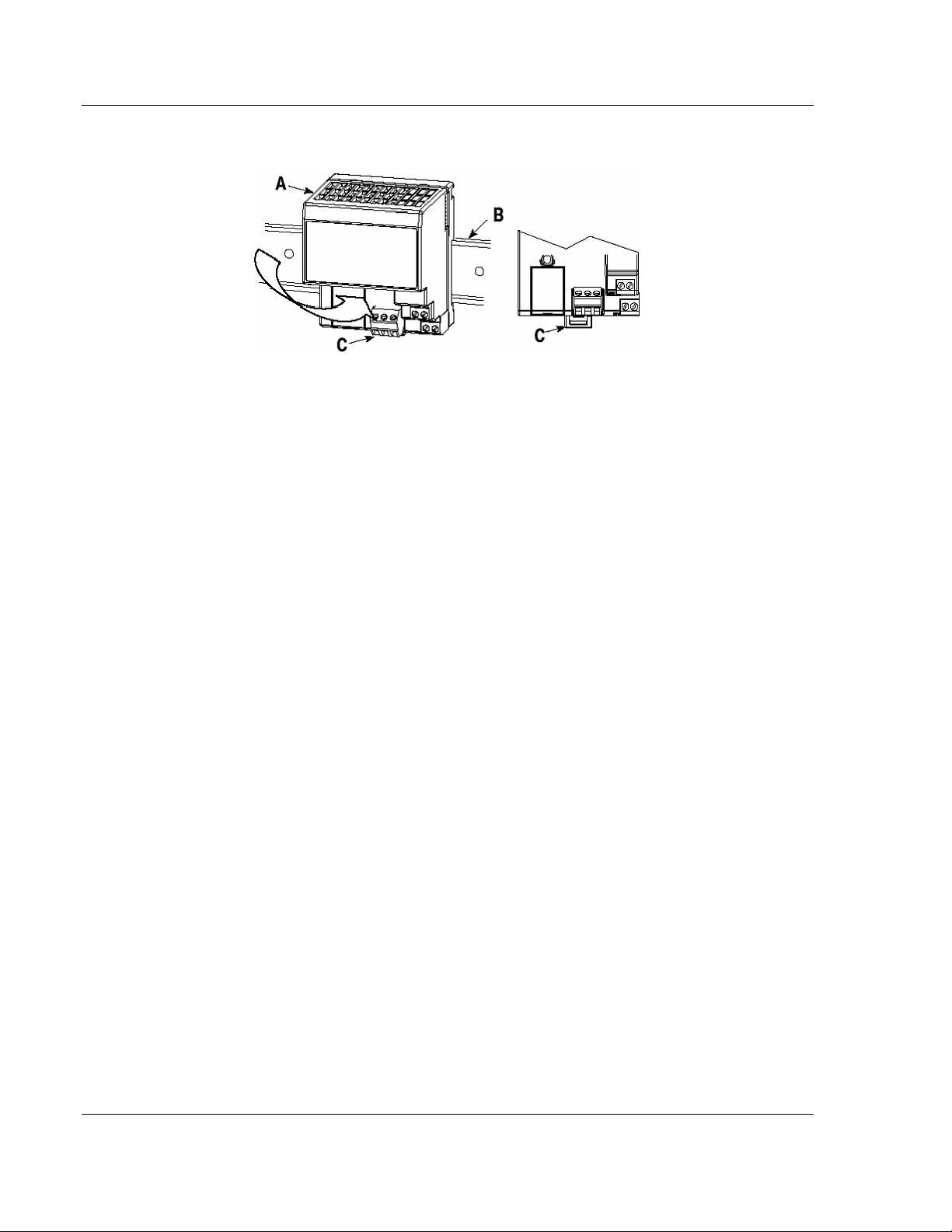
Component Identification
1 Modbus Adapter Module
2 Indicators
3 Communication reset pushbutton (PRL)
4 Access door to switches S1 and S2
5 Switches S1 and S2 (behind access door)
6 Modbus cable connector
7 +24V dc connections
8 24V common connections
9 Flexbus connector
ProSoft Technology, Inc. Page 13 of 55
October 27, 2010
Page 14
Module Configuration and Installation 3170-MBS ♦ Flex Platform
User Manual Modbus Slave Interface Module
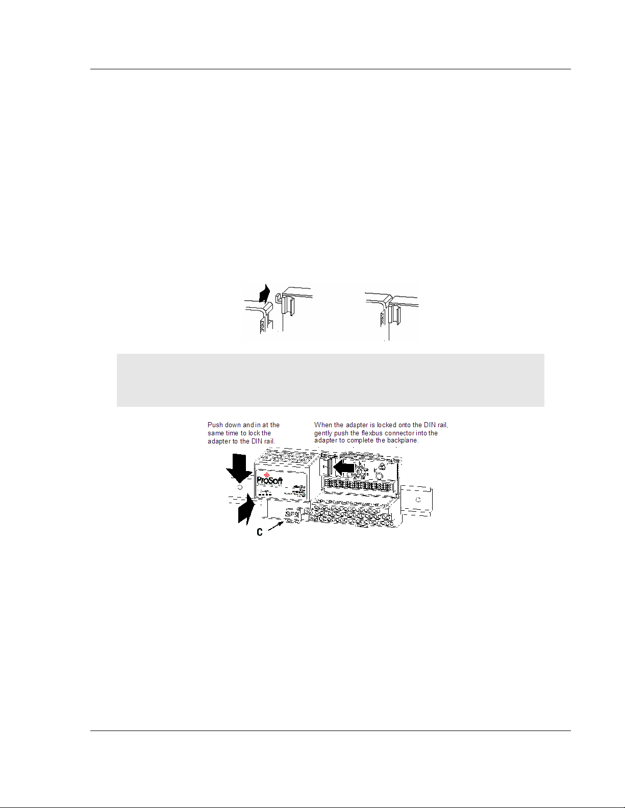
3.1 Mounting on a DIN-rail before installing the terminal base units
1 Position the Modbus adapter module A on a 35 X 7.5mm DIN-rail B
(Rockwell Automation pt. no. 199-DR1: 46277-3; EN 50022) at a slight angle.
2 Hook the lip on the rear of the adapter (A) onto the top of the DIN-rail (B),
and rotate the adapter module onto the rail.
3 Press the adapter module down onto the DIN-rail until flush. Locking tab (C)
will snap into position and lock the adapter module to the DIN-rail.
4 If the adapter module does not lock in place, use a screwdriver or similar
device to move the locking tab down while pressing the adapter module flush
onto the DIN-rail and release the locking tab to lock the adapter module in
place. If necessary, push up on the locking tab to lock.
5 Connect the adapter wiring as shown under "Wiring" later in this document.
Page 14 of 55 ProSoft Technology, Inc.
October 27, 2010
Page 15
3170-MBS ♦ Flex Platform Module Configuration and Installation
Modbus Slave Interface Module User Manual
3.2 Mounting (or Replacing) the module on an existing system
1 Remove the Modbus plug-in connector from the front of the adapter.
2 Disconnect any wiring jumpered to the adjacent terminal base.
3 Using a screwdriver or similar tool, open the lock and remove the module
from the base unit to which the adapter will be attached.
4 Push the flexbus connector toward the right side of the terminal base to
unplug the backplane connection.
5 Release the locking tab and remove the adapter.
6 Before installing the new adapter, notice the notch on the right rear of the
adapter. This notch accepts the hook on the terminal base unit. The notch is
open at the bottom. The hook and adjacent connection point keep the
terminal base and adapter tight together, reducing the possibility of a break in
communication over the backplane.
7 Complete the adapter mounting as shown below.
Attention: Make certain that the hook on the terminal base is properly hooked into the adapter.
Failure to lock the hook into the adjacent base/adapter can result in loss of communication on the
backplane.
8 If the adapter module does not lock in place, use a screwdriver or similar
device to move the locking tab C down while pressing the adapter module
flush onto the DIN-rail. Then release the locking tab to lock the adapter
module in place. If necessary, push up on the locking tab to lock.
9 Reinstall the module into the terminal base unit.
ProSoft Technology, Inc. Page 15 of 55
October 27, 2010
Page 16
Module Configuration and Installation 3170-MBS ♦ Flex Platform
User Manual Modbus Slave Interface Module
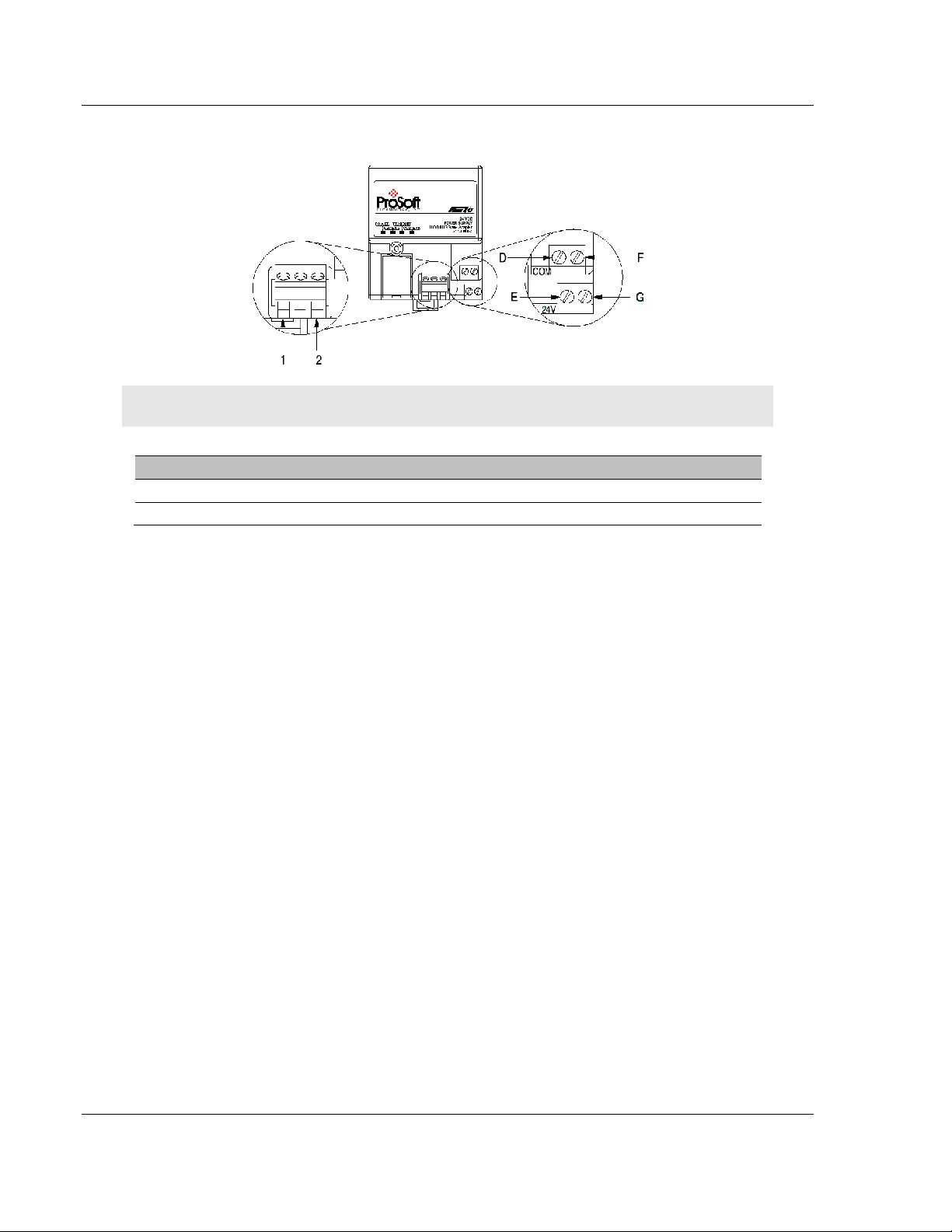
3.3 Wiring
Attention: When connecting wiring, torque terminal screws to 7 to 9 inch-pounds.
Connect To
TxRxD- 1
TxRxD+ 2
1 Connect the Modbus cable to the removable connector.
2 Connect +24V dc input to the left side of the lower connector, terminal E.
3 Connect 24V common to the left side of the upper connector, terminal D.
4 Connections G and F are used to pass 24V dc power (G) and 24V common
(F) to the next module in the series (if required).
3.3.1 RS-485 Tip
If communication in the RS-485 mode does not work at first, despite all attempts,
try switching termination polarities. Some manufacturers interpret + and -, or A
and B, polarities differently.
Page 16 of 55 ProSoft Technology, Inc.
October 27, 2010
Page 17
3170-MBS ♦ Flex Platform Module Configuration and Installation
Modbus Slave Interface Module User Manual
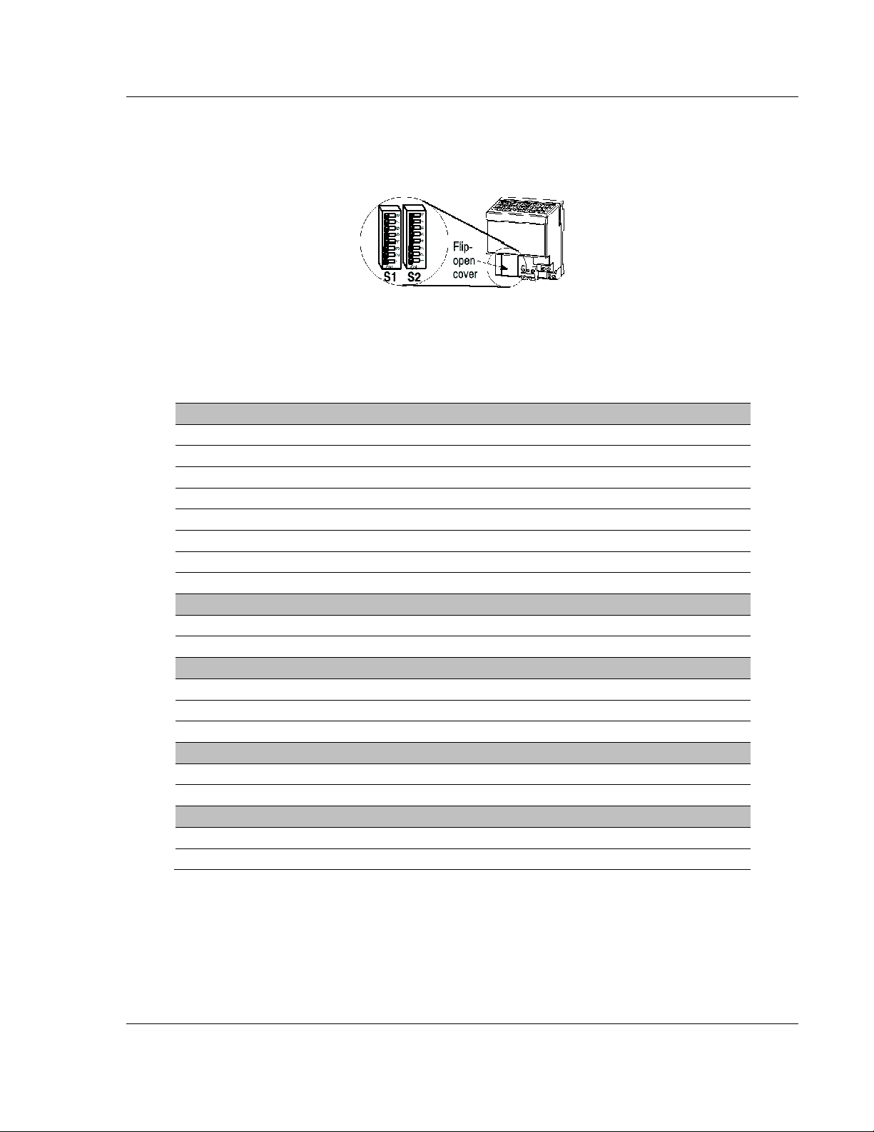
3.4 Setting the switches
The adapter switches are located under a flip-open cover on the front of the
adapter Set the switches as shown below.
1 Lift the hinged switch cover on the front of the adapter to expose the
switches.
2 Set the switches as shown below.
3 Cycle power to the adapter after setting the switches.
Baud Rate S1-1 S1-2 S1-3
1200 OFF OFF OFF
2400 ON OFF OFF
4800 OFF ON OFF
9600 ON ON OFF
19200 OFF OFF ON
38400 ON OFF ON
62.5K OFF ON ON
Undefined(Defaults to 19200) ON ON ON
Stop Bit S1-4
1 OFF
2 ON
Parity S1-5 S1-6
None OFF OFF
Odd ON OFF
Even OFF ON
Data Bits S1-7
8 OFF
7 ON
Modbus Mode S1-8
RTU OFF
ASCII ON
ProSoft Technology, Inc. Page 17 of 55
October 27, 2010
Page 18

Module Configuration and Installation 3170-MBS ♦ Flex Platform
User Manual Modbus Slave Interface Module
Address S2-1 S2-2 S2-3 S2-4 S2-5 S2-6 S2-7
0 OFF OFF OFF OFF OFF OFF OFF
1 ON OFF OFF OFF OFF OFF OFF
2 OFF ON OFF OFF OFF OFF OFF
3 ON ON OFF OFF OFF OFF OFF
4 ON OFF ON OFF OFF OFF OFF
5 OFF ON ON OFF OFF OFF OFF
6 ON ON ON OFF OFF OFF OFF
127 ON ON ON ON ON ON ON
Last State S2-8
Off OFF
Hold ON
Address 0 - Test Mode - Puts unit into a transmit only mode. Connect a terminal
at 19200 baud, 8N1 to view data.
Address 1 to 127 Valid Slave addresses.
Page 18 of 55 ProSoft Technology, Inc.
October 27, 2010
Page 19

3170-MBS ♦ Flex Platform Module Addressing
Modbus Slave Interface Module User Manual
4 Module Addressing
In This Chapter
Reading Discrete Inputs ........................................................................ 20
Writing Discrete Outputs........................................................................ 21
Each Flex or Integra module has 60 words of address space. 30 Input or Read
address and 30 Output or Write addresses. Data is mapped in two ways
Horizontal and Vertical.
With Horizontal addressing the adapter address the first input and output word
for each module incrementally. 40001 for module 0, 40002 for module 1 and so
on.
Vertical addressing increments the words for each module. For example, the
vertical read words for slot 0 start with 41001 and increment to 41015.
ProSoft Technology, Inc. Page 19 of 55
October 27, 2010
Page 20

Module Addressing 3170-MBS ♦ Flex Platform
User Manual Modbus Slave Interface Module
4.1 Reading Discrete Inputs
Each word address consists of 16 bits. These bits can be read as discrete inputs.
Word address 40001 corresponds to discrete inputs 10001 to 10016. 40002
corresponds to discrete inputs 10017 to 10032.
((Address - 40001) X 16) + 10001 This will give you Input address 0 of the
word.
Page 20 of 55 ProSoft Technology, Inc.
October 27, 2010
Page 21

3170-MBS ♦ Flex Platform Module Addressing
Modbus Slave Interface Module User Manual
4.2 Writing Discrete Outputs
Each word address consists of 16 bits. These bits can be written as discrete
outputs. Word address 40201 corresponds to discrete outputs 3201 to 3216.
40202 corresponds to discrete outputs 3217 to 3232.
((Address - 40001) X 16) + 1 This will give you the Output address 0 of the
word.
ProSoft Technology, Inc. Page 21 of 55
October 27, 2010
Page 22

Module Addressing 3170-MBS ♦ Flex Platform
User Manual Modbus Slave Interface Module
Page 22 of 55 ProSoft Technology, Inc.
October 27, 2010
Page 23

3170-MBS ♦ Flex Platform Status Information
Modbus Slave Interface Module User Manual
5 Status Information
In This Chapter
Adapter Status Word ............................................................................. 24
Module Status Words ............................................................................ 25
Module Information ................................................................................ 26
Modbus Function Counters ................................................................... 27
Modbus Status ...................................................................................... 28
ProSoft Technology, Inc. Page 23 of 55
October 27, 2010
Page 24

Status Information 3170-MBS ♦ Flex Platform
User Manual Modbus Slave Interface Module
5.1 Adapter Status Word
Bit: 15 14 13 12 11 10 9 8 7 6 5 4 3 2 1 0 40121
Not
Used
The input status word consists of:
I/O module fault bits - 1 status bit for each slot
I/O Last state Dip Switch S2-8(See 3170-MBS installation manual)
Bit Description Bit Explanation
I/O Module Fault
I/O Last State
0 This bit is set (1) when an error is detected in slot position 0.
1 This bit is set (1) when an error is detected in slot position 1.
2 This bit is set (1) when an error is detected in slot position 2.
3 This bit is set (1) when an error is detected in slot position 3.
4 This bit is set (1) when an error is detected in slot position 4.
5 This bit is set (1) when an error is detected in slot position 5.
6 This bit is set (1) when an error is detected in slot position 6.
7 This bit is set (1) when an error is detected in slot position 7.
8 = 1 for hold last state = 0 for off
9 to 15 Not used set to 0
I/O
Address
Slot 7 Slot 6 Slot 5 Slot 4 Slot 3 Slot 2 Slot 1 Slot 0
State
The adapter input status word bit descriptions are shown in the following table.
Page 24 of 55 ProSoft Technology, Inc.
October 27, 2010
Page 25

3170-MBS ♦ Flex Platform Status Information
Bit:
Modbus Slave Interface Module User Manual
5.2 Module Status Words
Slot Status: indicates the general health of the installed I/O module
Number of Words: either 3 or 15 words indeterminate if slot is empty.
Number of Read Words: the number of words which are to be read from the
I/O module, indeterminate if slot is empty.
15 14 13 12 11 10 9 8 7 6 5 4 3 2 1 0 40122
Status Total
Words
Type ID: a byte when combined with the Number of Words and Number of
Read Words form the Module ID which uniquely identifies a specific module
function, series and revision, indeterminate if slot is empty. Note that all of
bits 0 through 12 should be used in identifying a module.
Bit 15 1 = No answer, empty slot or dead module
Bit 14 1 = Either positive edge of bit 15 or bit 13 detected
Bit 13 1 = Bit failure, bad data on SerBus
Bit 12 1 = Number of words is 15, = 0 number of words is 3
Bits 11 to 8 Value = number of read words
Bits 7 to 0 Value = Type ID
Read
Words
Type
Identity
Address
to 40129
ProSoft Technology, Inc. Page 25 of 55
October 27, 2010
Page 26

Status Information 3170-MBS ♦ Flex Platform
User Manual Modbus Slave Interface Module
5.3 Module Information
3170-MBS Information Address
3170-MBS Product Revision Level 40154
3170-MBS Product Batch Number 40155
Page 26 of 55 ProSoft Technology, Inc.
October 27, 2010
Page 27

3170-MBS ♦ Flex Platform Status Information
Modbus Slave Interface Module User Manual
5.4 Modbus Function Counters
Modbus Port Function Code Counter Address
Function Code 1 40156
Function Code 2 40157
Function Code 3 40158
Function Code 4 40159
Function Code 5 40160
Function Code 6 40161
Reserved 40162
Function Code 16 40163
Modbus Status Address
Modbus Port: Responses to Host 40171
Modbus Port: No Responses to Host 40172
Modbus Port: Last Detected Error Condition 40173
ProSoft Technology, Inc. Page 27 of 55
October 27, 2010
Page 28

Status Information 3170-MBS ♦ Flex Platform
User Manual Modbus Slave Interface Module
5.5 Modbus Status
Responses to Host: This rollover counter increments every time a response is
issued by the 3170-MBS. Note that this counter increments whether the
response is a data response or an error code response.
No Responses to Host: This rollover counter increments every time a command
is seen on the Modbus port, which is not for this slave. This counter may be used
as a network activity counter.
Last Detected Error Condition: This value is the last error code transmitted to the
master by the 3170-MBS.
5.5.1 Error Codes
Code Name Description
0 All OK The port is operating as desired
1 Illegal Function An illegal function code request is being attempted
2 Bad Data Address The address, or the range of addresses, covered by a
3 Bad Data Value The value in the data field of the command from the host
4 Incomplete Response
Detected
10 Buffer Overflow The receive buffer has overflowed and reset the
254 Checksum Error The slave determined that the message checksum was in
request from the host is not within allowed limits
is not allowed.
This error indicates that an incomplete query was
received from a host query. This indicates that the slave
port is timing out too quickly (that is, application may
require some Inter-character Timeout Delay) or that the
host query is getting abbreviated, possibly by the
transmitting modem (last character getting dropped).
character count to 0. If this condition occurs try reading
fewer parameters at one time
error, and therefore discarded the message
Page 28 of 55 ProSoft Technology, Inc.
October 27, 2010
Page 29

3170-MBS ♦ Flex Platform Diagnostics and Troubleshooting
Modbus Slave Interface Module User Manual
6 Diagnostics and Troubleshooting
In This Chapter
LED Indicators ....................................................................................... 30
Troubleshooting: General ...................................................................... 31
The module provides information on diagnostics and troubleshooting in the
following forms:
LED status indicators on the front of the module provide general information
on the module's status.
Several hardware diagnostic capabilities have been implemented using the LED
indicator lights on the front of the adapter module. The following topics explain
the meaning of the individual LEDs and provide some troubleshooting tips.
ProSoft Technology, Inc. Page 29 of 55
October 27, 2010
Page 30

Diagnostics and Troubleshooting 3170-MBS ♦ Flex Platform
User Manual Modbus Slave Interface Module
6.1 LED Indicators
The following explains the operation of the LEDs.
LED Color Status Indication
Power Green On
Transmit Green Blink The Modbus port is transmitting data.
Receive Green Blink The Modbus port is receiving data. LED flashes on any character
COM
ERR
Amber Off
Normal state: The module is operating normally, with
communications being detected on the link
Blink
Modbus Communication Timeout: The port has not detected any
communications on the link for over 1 second. If the HOLD LAST
STATE dip switch is not set, the Input and Output images will be
forced to zero(0).
FLEX Backplane Communications Fail: The communication
adapter either does not detect any I/O modules plugged into the
backplane, or the backplane communications have failed.
activity, valid or invalid.
Normal State: When the error LED is off and the related port is
actively transferring data, there are no communication errors
Blink Periodic communication errors are occurring during data
communications. Error conditions that cause LED to blink include:
Bad Function Code
Invalid Register Address in command
Invalid Count value in command
Insufficient Characters in Modbus Packet
Checksum Error detected in packet
FLEX Backplane Communications Fail: The communication
adapter either does not detect any I/O modules plugged into the
backplane, or the backplane communications have failed
On This LED will stay on under several conditions:
Configuration Error
Recurring communication error
Page 30 of 55 ProSoft Technology, Inc.
October 27, 2010
Page 31

3170-MBS ♦ Flex Platform Diagnostics and Troubleshooting
Modbus Slave Interface Module User Manual
6.2 Troubleshooting: General
In order to assist in the troubleshooting of the adapter, the following table has
been put together. Use the following table to assist in application of the module,
but if additional questions or problems arise, please do not hesitate to contact us.
Problem Description Steps to take
No communications with
Host
RX LED on continuously Verify the polarity of the RS-485 communications connections. Not
COMM ERR LED blinks
periodically
Outputs Toggle Off If the HOLD LAST STATE dip switch is not set, the Output Image
ProSoft Technology, Inc. Page 31 of 55
October 27, 2010
If connected to the host and no communications are occurring, verify
the following:
Polarity of RS-485 cable connections (Either RX LED on
continuously or not toggling at all)
Slave Address: Valid addresses range from 1 to 127. Verify that
the address is encoded into the dip switch correctly
Baud Rate
Stop Bits, Parity, and Modbus Mode. There are valid
combinations of these parameters which are supported by the
adapter hardware. Verify that the configuration is one of the
following:
Modbus RTU and ASCII Modes
8 Data Bits, No Parity, 1 Stop
8 Data Bits, No Parity, 2 Stop
8 Data Bits, Odd Parity, 1 Stop
8 Data Bits, Even Parity, 1 Stop
Modbus ASCII Mode Only:
7 Data Bits, No Parity, 2 Stop
7 Data Bits, Odd Parity, 1 Stop
7 Data Bits, Even Parity, 1 Stop
7 Data Bits, Odd Parity, 2 Stop
7 Data Bits, Even Parity, 2 Stop
Modbus Mode: Verify that the host and the adapter are talking the
same implementation of the protocol, either RTU or ASCII.
all manufacturers adhere to the same +/- and A/B labeling
conventions. Do not be afraid to experiment with swapping the
polarity, no damage will occur to the hardware.
Periodic communication errors are occurring during data
communications. Error conditions which cause LED to blink include:
Bad Function Code
Invalid Register Address in command
Invalid Count value in command
Insufficient Characters in Modbus Packet
Checksum Error detected in packet
FLEX Backplane Communications Fail: The communication
adapter either does not detect any I/O modules plugged into the
backplane, or the backplane communications have failed
(and the Input Image) in the adapter will be forced to zero whenever
communications with the host has not been detected for over 1
second. The Outputs will be re-established by the adapter as soon
as a valid write command is received from the host.
To prevent the Toggling of the outputs, either set the HOLD LAST
STATE dip switch (S2 position 8), and/or assure the reliability of the
communications.
Page 32

Diagnostics and Troubleshooting 3170-MBS ♦ Flex Platform
User Manual Modbus Slave Interface Module
Page 32 of 55 ProSoft Technology, Inc.
October 27, 2010
Page 33

3170-MBS ♦ Flex Platform Example Address Mapping
Modbus Slave Interface Module User Manual
7 Example Address Mapping
In This Chapter
Application Example .............................................................................. 34
Address Map ......................................................................................... 35
Function Code Address Ranges ............................................................ 37
Work Sheets .......................................................................................... 38
ProSoft Technology, Inc. Page 33 of 55
October 27, 2010
Page 34

Example Address Mapping 3170-MBS ♦ Flex Platform
User Manual Modbus Slave Interface Module
7.1 Application Example
Use the information provided with your I/O to fill in the work sheets (page 38).
This will help you to decide the best way to address each I/O block.
In most applications Analog I/O will be addressed using the Vertical method.
Discrete I/O must be addressed using the Horizontal method only.
The Input Data will be read vertically as holding registers
The Underrange bits will be read as inputs
The Configuration Selection bits will be written as coils.
Page 34 of 55 ProSoft Technology, Inc.
October 27, 2010
Page 35

3170-MBS ♦ Flex Platform Example Address Mapping
Modbus Slave Interface Module User Manual
7.2 Address Map
Slot 0-H Slot 0-V Slot 1-H Slot 1-V Slot 2-H Slot 2-V Slot 3-H Slot 3-V
READ 40001 41001 40002 41016 40003 41031 40004 41046
40009 41002 40010 41017 40011 41032 40012 41047
40017 41003 40018 41018 40019 41033 40020 41048
40025 41004 40026 41019 40027 41034 40028 41049
40033 41005 40034 41020 40035 41035 40036 41050
40041 41006 40042 41021 40043 41036 40044 41051
40049 41007 40050 41022 40051 41037 40052 41052
40057 41008 40058 41023 40059 41038 40060 41053
40065 41009 40066 41024 40067 41039 40068 41054
40073 41010 40074 41025 40075 41040 40076 41055
40081 41011 40082 41026 40083 41041 40084 41056
40089 41012 40090 41027 40091 41042 40092 41057
40097 41013 40098 41028 40099 41043 40100 41058
40105 41014 40106 41029 40107 41044 40108 41059
40113 41015 40114 41030 40115 41045 40116 41060
Slot 4-H Slot 4-V Slot 5-H Slot 5-V Slot 6-H Slot 6-V Slot 7-H Slot 7-V
READ 40005 41061 40006 41076 40007 41091 40008 41106
40013 41062 40014 41077 40015 41092 40016 41107
40021 41063 40022 41078 40023 41093 40024 41108
40029 41064 40030 41079 40031 41094 40032 41109
40037 41065 40038 41080 40039 41095 40040 41110
40045 41066 40046 41081 40047 41096 40048 41111
40053 41067 40054 41082 40055 41097 40056 41112
40061 41068 40062 41083 40063 41098 40064 41113
40069 41069 40070 41084 40071 41099 40072 41114
40077 41070 40078 41085 40079 41100 40080 41115
40085 41071 40086 41086 40087 41101 40088 41116
40093 41072 40094 41087 40095 41102 40096 41117
40101 41073 40102 41088 40103 41103 40104 41118
40109 41074 40110 41089 40111 41104 40112 41119
40117 41075 40118 41090 40119 41105 40120 41120
Slot 0-H Slot04-V Slot 1-H Slot 1-V Slot 2-H Slot 2-V Slot 3-H Slot 3-V
ProSoft Technology, Inc. Page 35 of 55
October 27, 2010
Page 36

Example Address Mapping 3170-MBS ♦ Flex Platform
User Manual Modbus Slave Interface Module
Slot 0-H Slot04-V Slot 1-H Slot 1-V Slot 2-H Slot 2-V Slot 3-H Slot 3-V
WRITE 40201 41201 40202 41216 40203 41231 40204 41246
40209 41202 40210 41217 40211 41232 40212 41247
40217 41203 40218 41218 40219 41233 40220 41248
40225 41204 40226 41219 40227 41234 40228 41249
40233 41205 40234 41220 40235 41235 40236 41250
40241 41206 40242 41221 40243 41236 40244 41251
40249 41207 40250 41222 40251 41237 40252 41252
40257 41208 40258 41223 40259 41238 40260 41253
40265 41209 40266 41224 40267 41239 40268 41254
40273 41210 40274 41225 40275 41240 40276 41255
40281 41211 40282 41226 40283 41241 40284 41256
40289 41212 40290 41227 40291 41242 40292 41257
40297 41213 40298 41228 40299 41243 40300 41258
40305 41214 40306 41229 40307 41244 40308 41259
40313 41215 40314 41230 40315 41245 40316 41260
Slot 4-H Slot 4-V Slot 5-H Slot 5-V Slot 6-H Slot 6-V Slot 7-H Slot 7-V
WRITE 40205 41261 40206 41276 40207 41291 40208 41306
40294 41262 40214 41277 40215 41292 40216 41307
40383 41263 40222 41278 40223 41293 40224 41308
40472 41264 40230 41279 40231 41294 40232 41309
40561 41265 40238 41280 40239 41295 40240 41310
40650 41266 40246 41281 40247 41296 40248 41311
40739 41267 40254 41282 40255 41297 40256 41312
40828 41268 40262 41283 40263 41298 40264 41313
40917 41269 40270 41284 40271 41299 40272 41314
41006 41270 40278 41285 40279 41300 40280 41315
41095 41271 40286 41286 40287 41301 40288 41316
41184 41272 40294 41287 40295 41302 40296 41317
41273 41273 40302 41288 40303 41303 40304 41318
41362 41274 40310 41289 40311 41304 40312 41319
41451 41275 40318 41290 40319 41305 40320 41320
Page 36 of 55 ProSoft Technology, Inc.
October 27, 2010
Page 37

3170-MBS ♦ Flex Platform Example Address Mapping
Modbus Slave Interface Module User Manual
7.3 Function Code Address Ranges
Function Address
Type
1 Bit 0 to 1919 40001 to
Bit 3200 to 5119 40200 to
2 Bit 0 to 1919 40001 to
Bit 3200 to 5119 40200 to
3 Register 0 to 119 40001 to
Register 200 to 319 40200 to
4 Register 0 to 119 40001 to
Register 200 to 319 40200 to
5 Bit N/A N/A 3200 to 5119 40201 to
6 Register N/A N/A 200 to 319 40201 to
16 Register N/A N/A 200 to 319 40201 to
Horizontal
Read
Modbus
Address
40120
40320
40120
40320
40120
40320
40120
40320
Horizontal
Write
N/A N/A N/A N/A N/A N/A
N/A N/A N/A N/A N/A N/A
N/A N/A N/A N/A N/A N/A
N/A N/A N/A N/A N/A N/A
N/A N/A 1000 to
N/A N/A 1200 to
N/A N/A 1000 to
N/A N/A 1200 to
Modbus
Address
40320
40320
40320
Vertical
Read
1119
1319
1119
1319
Modbus
Address
41001 to
41120
41201 to
41320
41001 to
41120
41201 to
41320
Vertical
Write
Modbus
Address
N/A N/A
N/A N/A
N/A N/A
N/A N/A
N/A N/A N/A N/A
N/A N/A 1200 to
1319
N/A N/A 1200 to
1319
41201 to
41320
41201 to
41320
ProSoft Technology, Inc. Page 37 of 55
October 27, 2010
Page 38

Example Address Mapping 3170-MBS ♦ Flex Platform
User Manual Modbus Slave Interface Module
7.4 Work Sheets
Slot 0 Module Image Input Data HORIZ VERT
40001 41001
40009 41002
40017 41003
40025 41004
40033 41005
40041 41006
40049 41007
40057 41008
40065 41009
40073 41010
40081 41011
40089 41012
40097 41013
40105 41014
40113 41015
Slot 0 Module Image Output Data HORIZ VERT
40201 41201
40209 41202
40217 41203
40225 41204
40233 41205
40241 41206
40249 41207
40257 41208
40265 41209
40273 41210
40281 41211
40289 41212
40297 41213
40305 41214
40313 41215
Slot 1 Module Image Input Data HORIZ VERT
40002 41016
40010 41017
40018 41018
40026 41019
Page 38 of 55 ProSoft Technology, Inc.
October 27, 2010
Page 39

3170-MBS ♦ Flex Platform Example Address Mapping
Modbus Slave Interface Module User Manual
Slot 1 Module Image Input Data HORIZ VERT
40034 41020
40042 41021
40050 41022
40058 41023
40066 41024
40074 41025
40082 41026
40090 41027
40098 41028
40106 41029
40114 41030
Slot 1 Module Image Output Data HORIZ VERT
40202 41216
40210 41217
40218 41218
40226 41219
40234 41220
40242 41221
40250 41222
40258 41223
40266 41224
40274 41225
40282 41226
40290 41227
40298 41228
40306 41229
40314 41230
Slot 2 Module Image Input Data HORIZ VERT
40003 41031
40011 41032
40019 41033
40027 41034
40035 41035
40043 41036
40051 41037
40059 41038
40067 41039
40075 41040
ProSoft Technology, Inc. Page 39 of 55
October 27, 2010
Page 40

Example Address Mapping 3170-MBS ♦ Flex Platform
User Manual Modbus Slave Interface Module
Slot 2 Module Image Input Data HORIZ VERT
40083 41041
40091 41042
40099 41043
40107 41044
40115 41045
Slot 2 Module Image Output Data HORIZ VERT
40203 41231
40211 41232
40219 41233
40227 41234
40235 41235
40243 41236
40251 41237
40259 41238
40267 41239
40275 41240
40283 41241
40291 41242
40299 41243
40307 41244
40315 41245
Slot 3 Module Image Input Data HORIZ VERT
40004 41046
40012 41047
40020 41048
40028 41049
40036 41050
40044 41051
40052 41052
40060 41053
40068 41054
40076 41055
40084 41056
40092 41057
40100 41058
40108 41059
40116 41060
Page 40 of 55 ProSoft Technology, Inc.
October 27, 2010
Page 41

3170-MBS ♦ Flex Platform Example Address Mapping
Modbus Slave Interface Module User Manual
Slot 3 Module Image Output Data HORIZ VERT
40204 41246
40212 41247
40220 41248
40228 41249
40236 41250
40244 41251
40252 41252
40260 41253
40268 41254
40276 41255
40284 41256
40292 41257
40300 41258
40308 41259
40316 41260
Slot 4 Module Image Input Data HORIZ VERT
40005 41061
40013 41062
40021 41063
40029 41064
40037 41065
40045 41066
40053 41067
40061 41068
40069 41069
40077 41070
40085 41071
40093 41072
40101 41073
40109 41074
40117 41075
Slot 4 Module Image Output Data HORIZ VERT
40205 41261
40213 41262
40221 41263
40229 41264
40237 41265
40245 41266
ProSoft Technology, Inc. Page 41 of 55
October 27, 2010
Page 42

Example Address Mapping 3170-MBS ♦ Flex Platform
User Manual Modbus Slave Interface Module
Slot 4 Module Image Output Data HORIZ VERT
40253 41267
40261 41268
40269 41269
41277 41270
41285 41271
41293 41272
41301 41273
41309 41274
41317 41275
Slot 5 Module Image Input Data HORIZ VERT
40006 41076
40014 41077
40022 41078
40030 41079
40038 41080
40046 41081
40054 41082
40062 41083
40070 41084
40078 41085
40086 41086
40094 41087
40102 41088
40110 41089
40118 41090
Slot 5 Module Image Output Data HORIZ VERT
40206 41276
40214 41277
40222 41278
40230 41279
40238 41280
40246 41281
40254 41282
40262 41283
40270 41284
40278 41285
40286 41286
40294 41287
Page 42 of 55 ProSoft Technology, Inc.
October 27, 2010
Page 43

3170-MBS ♦ Flex Platform Example Address Mapping
Modbus Slave Interface Module User Manual
Slot 5 Module Image Output Data HORIZ VERT
40302 41288
40310 41289
40318 41290
Slot 6 Module Image Input Data HORIZ VERT
40007 41091
40015 41092
40023 41093
40031 41094
40039 41095
40047 41096
40055 41097
40063 41098
40071 41099
40079 41100
40087 41101
40095 41102
40103 41103
40111 41104
40119 41105
Slot 6 Module Image Output Data HORIZ VERT
40207 41291
40215 41292
40223 41293
40231 41294
40239 41295
40247 41296
40255 41297
40263 41298
40271 41299
40279 41300
40287 41301
40295 41302
40303 41303
40311 41304
40319 41305
ProSoft Technology, Inc. Page 43 of 55
October 27, 2010
Page 44

Example Address Mapping 3170-MBS ♦ Flex Platform
User Manual Modbus Slave Interface Module
Slot 7 Module Image Input Data HORIZ VERT
40008 41106
40016 41107
40024 41108
40032 41109
40040 41110
40048 41111
40056 41112
40064 41113
40072 41114
40080 41115
40088 41116
40096 41117
40104 41118
40112 41119
40120 41120
Slot 7 Module Image Output Data HORIZ VERT
40208 41306
40216 41307
40224 41308
40232 41309
40240 41310
40248 41311
40256 41312
40264 41313
40272 41314
40280 41315
40288 41316
40296 41317
40304 41318
40312 41319
40320 41320
Page 44 of 55 ProSoft Technology, Inc.
October 27, 2010
Page 45

3170-MBS ♦ Flex Platform Support, Service & Warranty
Modbus Slave Interface Module User Manual
8 Support, Service & Warranty
In This Chapter
Contacting Technical Support ............................................................... 45
Return Material Authorization (RMA) Policies and Conditions ............... 47
LIMITED WARRANTY ........................................................................... 49
Contacting Technical Support
ProSoft Technology, Inc. (ProSoft) is committed to providing the most efficient
and effective support possible. Before calling, please gather the following
information to assist in expediting this process:
1 Product Version Number
2 System architecture
3 Network details
If the issue is hardware related, we will also need information regarding:
1 Module configuration and associated ladder files, if any
2 Module operation and any unusual behavior
3 Configuration/Debug status information
4 LED patterns
5 Details about the serial, Ethernet or fieldbus devices interfaced to the module,
if any.
Note: For technical support calls within the United States, an after-hours answering system allows
24-hour/7-days-a-week pager access to one of our qualified Technical and/or Application Support
Engineers.
ProSoft Technology, Inc. Page 45 of 55
October 27, 2010
Page 46

Support, Service & Warranty 3170-MBS ♦ Flex Platform
Internet
User Manual Modbus Slave Interface Module
Web Site: www.prosoft-technology.com/support
E-mail address: support@prosoft-technology.com
Asia Pacific
(location in Malaysia)
Asia Pacific
(location in China)
Europe
(location in Toulouse,
France)
Europe
(location in Dubai, UAE)
Tel: +603.7724.2080, E-mail: asiapc@prosoft-technology.com
Languages spoken include: Chinese, English
Tel: +86.21.5187.7337 x888, E-mail: asiapc@prosoft-technology.com
Languages spoken include: Chinese, English
Tel: +33 (0) 5.34.36.87.20,
E-mail: support.EMEA@prosoft-technology.com
Languages spoken include: French, English
Tel: +971-4-214-6911,
E-mail: mea@prosoft-technology.com
Languages spoken include: English, Hindi
North America
(location in California)
Tel: +1.661.716.5100,
E-mail: support@prosoft-technology.com
Languages spoken include: English, Spanish
Latin America
(Oficina Regional)
Tel: +1-281-2989109,
E-Mail: latinam@prosoft-technology.com
Languages spoken include: Spanish, English
Latin America
(location in Puebla, Mexico)
Tel: +52-222-3-99-6565,
E-mail: soporte@prosoft-technology.com
Languages spoken include: Spanish
Brasil
(location in Sao Paulo)
Tel: +55-11-5083-3776,
E-mail: brasil@prosoft-technology.com
Languages spoken include: Portuguese, English
Page 46 of 55 ProSoft Technology, Inc.
October 27, 2010
Page 47

3170-MBS ♦ Flex Platform Support, Service & Warranty
Modbus Slave Interface Module User Manual
8.1 Return Material Authorization (RMA) Policies and Conditions
The following Return Material Authorization (RMA) Policies and Conditions
(collectively, "RMA Policies") apply to any returned product. These RMA Policies
are subject to change by ProSoft Technology, Inc., without notice. For warranty
information, see Limited Warranty (page 49). In the event of any inconsistency
between the RMA Policies and the Warranty, the Warranty shall govern.
8.1.1 Returning Any Product
a) In order to return a Product for repair, exchange, or otherwise, the
Customer must obtain a Return Material Authorization (RMA) number
from ProSoft Technology and comply with ProSoft Technology shipping
instructions.
b) In the event that the Customer experiences a problem with the Product for
any reason, Customer should contact ProSoft Technical Support at one of
the telephone numbers listed above (page 45). A Technical Support
Engineer will request that you perform several tests in an attempt to
isolate the problem. If after completing these tests, the Product is found to
be the source of the problem, we will issue an RMA.
c) All returned Products must be shipped freight prepaid, in the original
shipping container or equivalent, to the location specified by ProSoft
Technology, and be accompanied by proof of purchase and receipt date.
The RMA number is to be prominently marked on the outside of the
shipping box. Customer agrees to insure the Product or assume the risk
of loss or damage in transit. Products shipped to ProSoft Technology
using a shipment method other than that specified by ProSoft Technology,
or shipped without an RMA number will be returned to the Customer,
freight collect. Contact ProSoft Technical Support for further information.
d) A 10% restocking fee applies to all warranty credit returns, whereby a
Customer has an application change, ordered too many, does not need,
etc. Returns for credit require that all accessory parts included in the
original box (i.e.; antennas, cables) be returned. Failure to return these
items will result in a deduction from the total credit due for each missing
item.
ProSoft Technology, Inc. Page 47 of 55
October 27, 2010
Page 48

Support, Service & Warranty 3170-MBS ♦ Flex Platform
User Manual Modbus Slave Interface Module
8.1.2 Returning Units Under Warranty
A Technical Support Engineer must approve the return of Product under ProSoft
Technology’s Warranty:
a) A replacement module will be shipped and invoiced. A purchase order will
be required.
b) Credit for a product under warranty will be issued upon receipt of
authorized product by ProSoft Technology at designated location
referenced on the Return Material Authorization
i. If a defect is found and is determined to be customer generated, or if
the defect is otherwise not covered by ProSoft Technology s warranty,
there will be no credit given. Customer will be contacted and can
request module be returned at their expense;
ii. If defect is customer generated and is repairable, customer can
authorize ProSoft Technology to repair the unit by providing a
purchase order for 30% of the current list price plus freight charges,
duties and taxes as applicable.
8.1.3 Returning Units Out of Warranty
a) Customer sends unit in for evaluation to location specified by ProSoft
Technology, freight prepaid.
b) If no defect is found, Customer will be charged the equivalent of $100
USD, plus freight charges, duties and taxes as applicable. A new
purchase order will be required.
c) If unit is repaired, charge to Customer will be 30% of current list price
(USD) plus freight charges, duties and taxes as applicable. A new
purchase order will be required or authorization to use the purchase order
submitted for evaluation fee.
The following is a list of non-repairable units:
o
3150 - All
o
3750
o
3600 - All
o
3700
o
3170 - All
o
3250
o
1560 - Can be repaired, only if defect is the power supply
o
1550 - Can be repaired, only if defect is the power supply
o
3350
o
3300
o
1500 - All
Page 48 of 55 ProSoft Technology, Inc.
October 27, 2010
Page 49

3170-MBS ♦ Flex Platform Support, Service & Warranty
Modbus Slave Interface Module User Manual
8.2 LIMITED WARRANTY
This Limited Warranty ("Warranty") governs all sales of hardware, software, and
other products (collectively, "Product") manufactured and/or offered for sale by
ProSoft Technology, Incorporated (ProSoft), and all related services provided by
ProSoft, including maintenance, repair, warranty exchange, and service
programs (collectively, "Services"). By purchasing or using the Product or
Services, the individual or entity purchasing or using the Product or Services
("Customer") agrees to all of the terms and provisions (collectively, the "Terms")
of this Limited Warranty. All sales of software or other intellectual property are, in
addition, subject to any license agreement accompanying such software or other
intellectual property.
8.2.1 What Is Covered By This Warranty
a) Warranty On New Products: ProSoft warrants, to the original purchaser,
that the Product that is the subject of the sale will (1) conform to and
perform in accordance with published specifications prepared, approved
and issued by ProSoft, and (2) will be free from defects in material or
workmanship; provided these warranties only cover Product that is sold as
new. This Warranty expires three (3) years from the date of shipment for
Product purchased on or after January 1st, 2008, or one (1) year from the
date of shipment for Product purchased before January 1st, 2008 (the
"Warranty Period"). If the Customer discovers within the Warranty Period
a failure of the Product to conform to specifications, or a defect in material
or workmanship of the Product, the Customer must promptly notify
ProSoft by fax, email or telephone. In no event may that notification be
received by ProSoft later than 39 months from date of original shipment.
Within a reasonable time after notification, ProSoft will correct any failure
of the Product to conform to specifications or any defect in material or
workmanship of the Product, with either new or remanufactured
replacement parts. ProSoft reserves the right, and at its sole discretion,
may replace unrepairable units with new or remanufactured equipment.
All replacement units will be covered under warranty for the 3 year period
commencing from the date of original equipment purchase, not the date of
shipment of the replacement unit. Such repair, including both parts and
labor, will be performed at ProSoft’s expense. All warranty service will be
performed at service centers designated by ProSoft.
b) Warranty On Services: Materials and labor performed by ProSoft to repair
a verified malfunction or defect are warranteed in the terms specified
above for new Product, provided said warranty will be for the period
remaining on the original new equipment warranty or, if the original
warranty is no longer in effect, for a period of 90 days from the date of
repair.
ProSoft Technology, Inc. Page 49 of 55
October 27, 2010
Page 50

Support, Service & Warranty 3170-MBS ♦ Flex Platform
User Manual Modbus Slave Interface Module
8.2.2 What Is Not Covered By This Warranty
a) ProSoft makes no representation or warranty, expressed or implied, that
the operation of software purchased from ProSoft will be uninterrupted or
error free or that the functions contained in the software will meet or
satisfy the purchaser’s intended use or requirements; the Customer
assumes complete responsibility for decisions made or actions taken
based on information obtained using ProSoft software.
b) This Warranty does not cover the failure of the Product to perform
specified functions, or any other non-conformance, defects, losses or
damages caused by or attributable to any of the following: (i) shipping; (ii)
improper installation or other failure of Customer to adhere to ProSoft’s
specifications or instructions; (iii) unauthorized repair or maintenance; (iv)
attachments, equipment, options, parts, software, or user-created
programming (including, but not limited to, programs developed with any
IEC 61131-3, "C" or any variant of "C" programming languages) not
furnished by ProSoft; (v) use of the Product for purposes other than those
for which it was designed; (vi) any other abuse, misapplication, neglect or
misuse by the Customer; (vii) accident, improper testing or causes
external to the Product such as, but not limited to, exposure to extremes
of temperature or humidity, power failure or power surges; or (viii)
disasters such as fire, flood, earthquake, wind and lightning.
c) The information in this Agreement is subject to change without notice.
ProSoft shall not be liable for technical or editorial errors or omissions
made herein; nor for incidental or consequential damages resulting from
the furnishing, performance or use of this material. The user guide
included with your original product purchase from ProSoft contains
information protected by copyright. No part of the guide may be duplicated
or reproduced in any form without prior written consent from ProSoft.
8.2.3 Disclaimer Regarding High Risk Activities
Product manufactured or supplied by ProSoft is not fault tolerant and is not
designed, manufactured or intended for use in hazardous environments requiring
fail-safe performance including and without limitation: the operation of nuclear
facilities, aircraft navigation of communication systems, air traffic control, direct
life support machines or weapons systems in which the failure of the product
could lead directly or indirectly to death, personal injury or severe physical or
environmental damage (collectively, "high risk activities"). ProSoft specifically
disclaims any express or implied warranty of fitness for high risk activities.
Page 50 of 55 ProSoft Technology, Inc.
October 27, 2010
Page 51

3170-MBS ♦ Flex Platform Support, Service & Warranty
Modbus Slave Interface Module User Manual
8.2.4 Intellectual Property Indemnity
Buyer shall indemnify and hold harmless ProSoft and its employees from and
against all liabilities, losses, claims, costs and expenses (including attorney’s
fees and expenses) related to any claim, investigation, litigation or proceeding
(whether or not ProSoft is a party) which arises or is alleged to arise from Buyer’s
acts or omissions under these Terms or in any way with respect to the Products.
Without limiting the foregoing, Buyer (at its own expense) shall indemnify and
hold harmless ProSoft and defend or settle any action brought against such
Companies to the extent based on a claim that any Product made to Buyer
specifications infringed intellectual property rights of another party. ProSoft
makes no warranty that the product is or will be delivered free of any person’s
claiming of patent, trademark, or similar infringement. The Buyer assumes all
risks (including the risk of suit) that the product or any use of the product will
infringe existing or subsequently issued patents, trademarks, or copyrights.
a) Any documentation included with Product purchased from ProSoft is
protected by copyright and may not be duplicated or reproduced in any
form without prior written consent from ProSoft.
b) ProSoft’s technical specifications and documentation that are included
with the Product are subject to editing and modification without notice.
c) Transfer of title shall not operate to convey to Customer any right to make,
or have made, any Product supplied by ProSoft.
d) Customer is granted no right or license to use any software or other
intellectual property in any manner or for any purpose not expressly
permitted by any license agreement accompanying such software or other
intellectual property.
e) Customer agrees that it shall not, and shall not authorize others to, copy
software provided by ProSoft (except as expressly permitted in any
license agreement accompanying such software); transfer software to a
third party separately from the Product; modify, alter, translate, decode,
decompile, disassemble, reverse-engineer or otherwise attempt to derive
the source code of the software or create derivative works based on the
software; export the software or underlying technology in contravention of
applicable US and international export laws and regulations; or use the
software other than as authorized in connection with use of Product.
f) Additional Restrictions Relating To Software And Other Intellectual
Property
In addition to compliance with the Terms of this Warranty, Customers
purchasing software or other intellectual property shall comply with any
license agreement accompanying such software or other intellectual
property. Failure to do so may void this Warranty with respect to such
software and/or other intellectual property.
8.2.5 Disclaimer of all Other Warranties
The Warranty set forth in What Is Covered By This Warranty (page 49) are in lieu
of all other warranties, express or implied, including but not limited to the implied
warranties of merchantability and fitness for a particular purpose.
ProSoft Technology, Inc. Page 51 of 55
October 27, 2010
Page 52

Support, Service & Warranty 3170-MBS ♦ Flex Platform
User Manual Modbus Slave Interface Module
8.2.6 Limitation of Remedies **
In no event will ProSoft or its Dealer be liable for any special, incidental or
consequential damages based on breach of warranty, breach of contract,
negligence, strict tort or any other legal theory. Damages that ProSoft or its
Dealer will not be responsible for include, but are not limited to: Loss of profits;
loss of savings or revenue; loss of use of the product or any associated
equipment; loss of data; cost of capital; cost of any substitute equipment,
facilities, or services; downtime; the claims of third parties including, customers of
the Purchaser; and, injury to property.
** Some areas do not allow time limitations on an implied warranty, or allow the exclusion or
limitation of incidental or consequential damages. In such areas, the above limitations may not
apply. This Warranty gives you specific legal rights, and you may also have other rights which vary
from place to place.
8.2.7 Time Limit for Bringing Suit
Any action for breach of warranty must be commenced within 39 months
following shipment of the Product.
8.2.8 No Other Warranties
Unless modified in writing and signed by both parties, this Warranty is
understood to be the complete and exclusive agreement between the parties,
suspending all oral or written prior agreements and all other communications
between the parties relating to the subject matter of this Warranty, including
statements made by salesperson. No employee of ProSoft or any other party is
authorized to make any warranty in addition to those made in this Warranty. The
Customer is warned, therefore, to check this Warranty carefully to see that it
correctly reflects those terms that are important to the Customer.
8.2.9 Allocation of Risks
This Warranty allocates the risk of product failure between ProSoft and the
Customer. This allocation is recognized by both parties and is reflected in the
price of the goods. The Customer acknowledges that it has read this Warranty,
understands it, and is bound by its Terms.
Page 52 of 55 ProSoft Technology, Inc.
October 27, 2010
Page 53

3170-MBS ♦ Flex Platform Support, Service & Warranty
Modbus Slave Interface Module User Manual
8.2.10 Controlling Law and Severability
This Warranty shall be governed by and construed in accordance with the laws of
the United States and the domestic laws of the State of California, without
reference to its conflicts of law provisions. If for any reason a court of competent
jurisdiction finds any provisions of this Warranty, or a portion thereof, to be
unenforceable, that provision shall be enforced to the maximum extent
permissible and the remainder of this Warranty shall remain in full force and
effect. Any cause of action with respect to the Product or Services must be
instituted in a court of competent jurisdiction in the State of California.
ProSoft Technology, Inc. Page 53 of 55
October 27, 2010
Page 54

Support, Service & Warranty 3170-MBS ♦ Flex Platform
User Manual Modbus Slave Interface Module
Page 54 of 55 ProSoft Technology, Inc.
October 27, 2010
Page 55

3170-MBS ♦ Flex Platform Index
Modbus Slave Interface Module User Manual
Index
A
Adapter Status Word • 24
Address Map • 35
Allocation of Risks • 52
Application Example • 34
B
Battery Life Advisory • 3
C
Contacting Technical Support • 45, 47
Controlling Law and Severability • 53
D
Diagnostics and Troubleshooting • 29
Disclaimer of all Other Warranties • 51
Disclaimer Regarding High Risk Activities • 50
E
Error Codes • 28
Example Address Mapping • 33
F
Function Code Address Ranges • 37
Functional Overview • 11
G
General Specifications • 8
H
How to Contact Us • 2
I
Important Installation Instructions • 3
Installation • 14
Intellectual Property Indemnity • 51
L
LED Indicators • 30
Limitation of Remedies ** • 52
LIMITED WARRANTY • 47, 49
Module Status Words • 25
Mounting (or Replacing) the module on an existing
system • 15
Mounting on a DIN-rail before installing the terminal
base units • 14
MVI (Multi Vendor Interface) Modules • 3
N
No Other Warranties • 52
P
Pinouts • 3, 14, 15, 16
Product Specifications • 7
ProSoft Technology® Product Documentation • 2
R
Reading Discrete Inputs • 20
Return Material Authorization (RMA) Policies and
Conditions • 47
Returning Any Product • 47
Returning Units Out of Warranty • 48
Returning Units Under Warranty • 48
RS-485 and RS-422 Tip • 16
S
Setting the switches • 17
Status Information • 23
Support, Service & Warranty • 45
T
The Data Space in the module • 12
Time Limit for Bringing Suit • 52
Troubleshooting
General • 31
W
Warnings • 3
What Is Covered By This Warranty • 49, 51
What Is Not Covered By This Warranty • 50
Wiring • 16
Work Sheets • 34, 38
Writing Discrete Outputs • 21
Y
Your Feedback Please • 2
M
Markings • 4
Modbus Addressing Concepts • 11
Modbus Function Counters • 27
Modbus Specifications • 9
Modbus Status • 28
Module Addressing • 19
Module Configuration and Installation • 13
Module Information • 26
ProSoft Technology, Inc. Page 55 of 55
October 27, 2010
 Loading...