


ProMar |
Digital |
Performance Charging |
Visit ProMariner online at www.promariner.com, for a complete
selection of quality marine products...
Here are just a few:
ProMite Series - Recreational Grade Waterproof Marine Battery Chargers
ProSport Series - Heavy Duty Recreational Grade Waterproof
Marine Battery Chargers
ProTournament Series - Professional Grade Tournament
Waterproof Marine Battery Chargers
ProIsoCharge Series - Digitally Controlled Zero Loss Charging Isolators
Digital Mobile Charge In-Transit Chargers
Battery Maintainers
AC Plug Holders
Battery Isolators
Isolation Transformers
Galvanic Isolators and Monitored Systems
Corrosion Control Products
Waterproof Marine Binoculars
Gold Plated Fuses and Holders
A Complete Line of Hand Held Test Meters
Online Technical Support and Service Support
Visit frequently, we are always adding new products for your boating enjoyment!
Professional Mariner, LLC
200 International Drive, STE 195 Portsmouth, New Hampshire 03801 TEL: 603-433-4440
FAX: 603-433-4442 www.promariner.com
specifications subject to change without notice |
08/13 A |
ProMar |
Digital |
Performance Charging |
Global AC Input
Power Factor Corrected
100-260VAC50/60Hz
|
|
|
|
A R |
D I |
|
|
|
|
M |
|
G |
I |
|
|
O |
|
|
|
T |
|
R |
|
|
|
A |
|
P |
|
|
|
|
L |
|
|
|
energy |
||||
|
|
|
||||
 saving
technology
|
|
|
BC |
|
|
C |
E |
|
|
D |
™ |
|
C |
E |
|||
|
|
LIST |
|
||
ProNauticP Series Instruction Manual
Models |
Part No. |
Amperage |
Banks |
Volts |
ProNautic1210P |
63110 |
10 Amps |
2 Banks |
12 |
ProNautic1215P |
63115 |
15 Amps |
3 Banks |
12 |
ProNautic1220P |
63120 |
20 Amps |
3 Banks |
12 |
ProNautic1230P |
63130 |
30 Amps |
3 Banks |
12 |
ProNautic1240P |
63140 |
40 Amps |
3 Banks |
12 |
ProNautic1250P |
63150 |
50 Amps |
3 Banks |
12 |
ProNautic1260P |
63160 |
60 Amps |
3 Banks |
12 |
ProNautic2420P |
63170 |
20 Amps |
3 Banks |
24 |
ProNautic2430P |
63180 |
30 Amps |
3 Banks |
24 |
IMPORTANT NOTICE
This manual contains important safety and operating instructions for the ProNauticP Series Chargers. Please save and read all safety, operating and installation instructions before installing or applying AC power to your ProNauticP Charger.
Your Satisfaction is Important to Us!
Do not return this product to retailer or dealer for any service or warranty requirements.
Please call our Customer Care Department at 800-824-0524 from 8:30 am to 5pm Eastern Time for any warranty, service or installation assistance. Thank you - ProMariner Customer Care
PLEASE RECORD YOUR:
Model Number: |
|
Serial Number: |
|
Date of Purchase: |

1
Table of Contents |
|
|
Notes |
Introduction... |
2-3 |
|
|
CAUTIONS, WARNINGS AND SAFETY INSTRUCTIONS… |
4-8 |
|
|
Installation... |
9-12 |
|
|
Setup and Operation… |
13-17 |
|
|
Programming... |
18-19 |
|
|
Troubleshooting... |
20 |
|
|
Maintenance... |
21 |
|
|
Dimensions... |
22-24 |
|
|
Typical Wiring Configuration... |
25-27 |
|
|
Warranty Information... |
28 |
|
|
Unpacking and Inspection:
Thoroughly inspect your ProNauticP unit. The package should contain the following:
1)ProNauticP Charger
2)Parts package including:
a.Owners/Installation manual
b.Warranty Card
c.Temperature Probe
DAMAGE – If any parts are missing or damaged, or the unit has been damaged in shipping contact ProMariner Customer Service at 1-800-824-0524, please do not take it back to place of purchase.
DO NOT attempt to install or operate the unit if it has been damaged in any way.
2
Notes |
|
Introduction |
20
ProNautic12•60 P
Power Factor Corrected & Global AC Input
10 |
|
|
|
|
|
|
|
|
|
|
|
|
|
|
|
|
|
|
|
|
|
|
|
|
|
|
|
|
|
|
|
ProMar |
Digital |
|
|
|
|
|
|
|
|
|
Performance Charging |
|
|
|
|
|
|
|
|
||||||
|
|
|
|
|
|
|
|
SYSTEM |
|
DC |
OUTPUT |
LEVELS |
|
|
|
|
|
|
|
|
|
|
|
|
|
|
|
|
9 |
|
|
|
AC Power |
|
|
|
|
|
|
|
|
|
|
|
|
|
|
|
|
|
|
|
|
|
|
|
|
|
|
|
Auto Temp Control |
|
|
|
|
Volts |
|
|
|
|
|
Amps |
|
|
|
|
|
|
|
|
|
|
|
|
||
|
|
|
|
Active PFC |
|
|
|
|
|
0% |
|
|
|
100% |
|
|
|
|
|
|
|
|
|
|
|
|
||
|
|
|
|
Variable SpeedCooling 1 2 3 |
|
|
|
|
|
Charger |
Output |
|
|
|
|
|
|
|
|
|
|
|
|
|
|
|
||
|
|
|
|
AUTO CONSERVATION |
MODES |
|
|
Standby |
|
|
Battery Health |
Program |
|
|
|
|
|
|
|
|
|
|
|
|
||||
|
|
|
|
Charger Mode |
|
|
Charging |
|
|
Conditioning |
|
|
Auto |
|
Maintain |
|
|
|
|
|
|
|
|
|
|
|||
|
|
|
|
Self Test |
|
Battery |
Profiles |
|
Equalization |
|
Charger |
Conditions |
|
|
|
|
|
|
|
|
|
|
||||||
5 |
|
|
|
OK |
|
Preset-1 |
|
Preset-2 |
Flooded |
|
|
Reverse Polarity |
|
|
|
|
|
|
|
|
|
|
||||||
|
|
|
Fault |
|
Sealed |
|
|
DC Volts Low |
|
|
|
|
|
|
|
|
|
|
||||||||||
|
|
|
|
|
|
|
|
|
|
AGM |
|
|
|
|
DC Volts High |
|
|
|
|
|
|
|
|
|
|
|||
|
|
|
|
|
|
|
|
|
|
GEL |
|
|
|
|
Charger High |
Temp |
|
|
|
|
|
|
|
|
|
|||
|
|
|
|
SETUP |
|
|
|
LiFePO4-Lithium |
|
|
Check Fan |
|
|
|
|
|
|
|
|
|
|
|||||||
|
|
|
|
ENTER |
|
|
|
Calcium/Custom |
|
|
|
|
|
|
|
|
|
|
|
|
|
|
|
|||||
|
|
|
|
|
|
|
|
|
|
|
|
|
|
|
|
|
|
|
|
|
|
|
|
|
||||
|
|
|
|
DISPLAY WAKE UP: Press any key; SELF TEST: Hold all keys |
5 seconds |
|
|
|
|
|
|
|
|
|
|
|
|
|
|
|
|
|
|
|
|
|||
|
|
|
|
AVOID SERIOUS INJURY OR DEATH FROM ELECTRICAL |
SHOCK. |
BEFORE OPENING |
ELECTRICAL BURN AND |
SPARK HAZARD. BEFORE |
OPENING |
|
|
|
|
|
|
|
|
|
||||||||||
|
|
|
|
TURN OFF AC SUPPLY POWER. DO NOT EXPOSE TO |
RAIN OR |
SPRAY. |
|
|
DISCONNECT CHARGER |
CONNECTIONS AT BATTERIES. |
|
|
|
|
|
|
|
|
|
|
||||||||
|
|
|
|
CHOC ELECTRIQUES PEUVENT PROVOQUER LA MORT OU |
DE SERIEUSE BLESSURES. |
(DANGER DE BRULURES |
ELECTRIQUE ET ETINCELLES). AVANT |
D'OUVRIR |
LA |
|
|
|
|
|
|
|
|
|||||||||||
|
|
|
|
AVANTD'OUVRIRLABOITE,COUPERLECOURANT.NEPAS |
EXPOSERAUXINTEMPÉRIES. |
BOITE DECONNECTER LES |
CONNECTIONS ENTRE CHARGEUR |
ET BATTERIE. |
|
|
|
|
|
|
|
|
||||||||||||
|
|
|
|
WARNING: HIGH VOLTAGE |
|
|
WARNING: LOW VOLTAGE |
|
|
|
|
|
|
|
|
|||||||||||||
|
|
|
|
ATTENTION : HAUTE TENSION |
|
|
ATTENTION : BASSE TENSION |
|
|
|
|
|
|
|
|
|||||||||||||
|
|
|
|
|
|
|
|
|
|
|
|
|
|
|
|
|
|
|
|
|
|
|
|
|
|
|
|
|
|
|
|
|
|
|
|
|
|
|
|
|
|
|
|
|
|
|
|
|
|
|
|
|
|
|
|
|
|
|
|
|
|
|
|
|
|
|
|
|
|
|
|
|
|
|
|
|
|
|
|
|
|
|
|
|
|
|
|
|
|
|
|
|
|
|
|
|
|
|
|
|
|
|
|
|
|
|
|
|
|
|
|
|
|
|
|
8 |
7 |
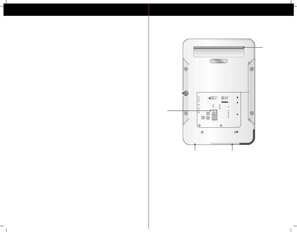
1. Cooling Vent |
6. AC and DC Connection Cover |
2. Amperage Out Display |
7. DC Side Terminations |
3. Percentage of Outputs Used |
8. AC Side Terminations |
4. Faults |
9. Voltage Out Display |
5. Charging Profile Selected |
10. ABYC Recommended Bonding Stud |
1
2
3
4
6
12 Volt Models |
|
24 Volt Models |
|
10 Amps |
PP1210 – 2 Output |
20 Amps |
PP2420 – 3 Outputs |
15 Amps |
PP1215 – 3 Outputs |
30 Amps |
PP2430 – 3 Outputs |
20 Amps |
PP1220 – 3 Outputs |
|
|
30 Amps |
PP1230 – 3 Outputs |
|
|
40 Amps |
PP1240 – 3 Outputs |
|
|
50 Amps |
PP1250 – 3 Outputs |
|
|
60 Amps |
PP1260 – 3 Outputs |
|
|
|
|
|
|

3
Introduction
Thank you from all of us at Professional Mariner, LLC and congratulations on the recent purchase of your ProNauticP Series On-Board Marine Battery Charger. The ProNauticP On-Board Marine Battery Charger is the latest in advanced microprocessor controlled battery charging technology and is ideal for: cuddy, cruiser, sail, house boats, yachts commercial offshore and sport fishing boats.
The ProNauticP Series is designed to be installed in an area where the charger will NOT be subjected to water. Recommended installation is in an engine room or dry compartments where 6 inches of clearance on all sides is available.
The ProNauticP Series On-Board Marine Battery Charger incorporates industry leading technology, delivering fully automatic and sequential multi-stage charging that provides electronically controlled charging, conditioning and maintenance of all batteries and or banks connected.
High Line Features:
Power Factor Correction - This ensures efficient operation of the unit regardless of the quality of the power input.
Automatic Global AC Input - This unit has been designed for 100-240VAC operation at 60Hz (US) and 50Hz. (European & Australia)
Digital Information Center - Displays real-time state of charge, charge mode and voltage/amperage in an easy to read format.
NOTE: During Standby Energy Savings Mode only the Power, Standby and Auto Maintain LED’s will be illuminated
Multiple Battery Type Charging Capability - User selected battery types including new technologies such as Lithium (LiFePO4) as well as a custom setting to manually select the desired voltages.
Selectable Power Level - Adjust amperage draw of the unit to prevent it from competing with other appliances when only a lower amperage shore / station power hookup is available.
|
savingenergy |
Conservation Energy Saver Mode - After fully charging and conditioning batteries, |
||||
|
|
OM |
A R D I |
G |
TI |
|
P |
R |
|
|
|
L |
|
|
|
|
technology |
|
ProNauticP’s Energy Saver Mode will monitor and Auto Maintain batteries only when needed, |
|
|
|
|
BC |
|
|
|
|
|
C |
EC LISTED |
|
||
maintaining a full state of charge. This significantly reduces AC power consumption while lowering operating costs and maximizing reserve power performance.
Standard Features:
Fully Automatic – Charge rates and battery maintenance automatically controlled based on battery chemistry selected. Automatically selects between charge, conditioning and ready.
Stylish and compact on-board marine charger:
Expanded LED operation status center with fault indicators
Easy to navigate 3 button command center
Electronic variable speed cooling
No drip shield required venting design
DC cable organizer
AC cable organizer
ABYC recommended bonding system connection
28
Warranty
WARRANTY CARD CAN BE REGISTERED AT WWW.PROMARINER.COM or the warranty card included in this manual can be completed and sent to ProMariner by mail.
PRONAUTICP SERIES ON-BOARD MARINE BATTERY CHARGER FIVE YEAR WARRANTY
Each ProMariner ProNauticP Series Model is guaranteed against defects in material and workmanship for five full years after purchase. Each serial numbered product has an additional repair adjustment provision after the 5 year limited warranty that limits the maximum charge for repair or replacement to 50% of the current list price, plus shipping and handling.
•Warranty and repair adjustment calculated from manufacture date if not registered or proof of purchase within two weeks of sale.
•Warranty void if unauthorized repairs attempted.
•Water damage not covered under warranty
•Customer is responsible for shipping to ProMariner.
•Cosmetic repairs are done at the owner’s request and expense.
Purchase or other acceptance of the product shall be on the condition and agreement that Professional Mariner, LLC SHALL NOT BE LIABLE FOR INCIDENTAL OR CONSEQUENTIAL DAMAGES OF ANY KIND. (Some states do not allow the exclusion or limitation of incidental or consequential damages, so the above limitations may not apply to you.) This warranty is made in lieu of all other obligations or liabilities on the part of Professional Mariner. Professional Mariner neither assumes nor authorizes any person for any obligation or liability in connection with the sale of this product.
To make a claim under warranty, go to www.promariner.com and click on the support tab and follow the instructions making sure to identify the product and the problem. If you can not use our online warranty claim registration, please feel free to call ProMariner at the toll free number listed below. Professional Mariner will make its best effort to repair or replace the product, if found defective within the terms of the warranty, within 30 days after return of the product to the company. Professional Mariner will ship the repaired or replaced product back to the purchaser. This warranty gives you specific legal rights, and you may also have other rights, which vary from state to state. This warranty is in lieu of all others expressed or implied.
Factory Service Center & Technical Support
Professional Mariner, LLC
200 International Drive, STE 195
Portsmouth, NH 03801.
Tel: 1-800-824-0524
Professional Mariner, LLC
Tel: (603) 433-4440 / Fax: (603) 433-4442

27
Typical Wiring Configurations
Typical Single12 Volt DC Common Ground Installation:
Case Ground |
ProNautic12•60 P |
Power Factor Corrected & Global AC Input |
|
1 Size Smaller than the + |
|
L
N
G
AC Input
Main Grounding Bus to Engine Negative
|
|
|
|
ProMar |
Digital |
|
|
|
|
|
|
Performance Charging |
|
|
|||||
|
|
|
|
|
|
|
|
|
|
|
SYSTEM DC OUTPUT LEVELS |
|
|
|
|
||||
|
|
|
|
AC Power |
|
|
|
|
|
|
|
|
|
|
|
||||
|
|
|
|
Auto Temp Control |
|
|
|
Volts |
|
|
Amps |
|
|
||||||
|
|
|
|
Active PFC |
|
|
|
|
|
|
|
|
|
|
|
|
|||
|
|
|
|
|
|
|
|
|
0% |
|
|
|
|
|
|||||
|
|
|
|
Variable SpeedCooling 1 2 3 |
|
|
|
|
100% |
|
|
|
|||||||
|
|
|
|
|
|
|
|
|
Charger Output |
|
|
||||||||
|
|
|
|
AUTO CONSERVATION |
MODES |
|
Standby |
|
Battery Health Program |
|
|
||||||||
|
|
|
|
Charger Mode |
|
Charging |
|
Conditioning |
Auto Maintain |
|
|
||||||||
|
|
|
|
Self Test |
Battery Profiles |
Equalization |
Charger Conditions |
|
|
||||||||||
|
|
|
|
OK |
Preset-1 |
Preset-2 |
Flooded |
Reverse Polarity |
|
|
|||||||||
|
|
|
|
Fault |
Sealed |
DC Volts Low |
|
|
|||||||||||
|
|
|
|
|
|
|
|
|
|
|
|
|
AGM |
|
|
DC Volts High |
|
|
|
|
|
|
|
|
|
|
|
|
|
|
|
|
GEL |
|
|
Charger High Temp |
|
|
|
|
|
|
|
SETUP |
|
|
|
LiFePO4-Lithium |
Check Fan |
|
|
||||||||
|
|
|
|
ENTER |
|
|
|
Calcium/Custom |
|
|
|
|
|||||||
|
|
|
|
|
|
|
|
|
|
|
|
|
|
|
|
|
|||
|
|
|
|
DISPLAY WAKE UP: Press any key; SELF TEST: Hold all keys 5 seconds |
|
|
|
|
|
|
|
||||||||
|
|
|
|
AVOID SERIOUS INJURY OR DEATH FROM ELECTRICAL SHOCK. BEFORE OPENING |
ELECTRICAL BURN AND SPARK HAZARD. BEFORE OPENING |
|
|
||||||||||||
|
|
|
|
TURN OFF AC SUPPLY POWER. DO NOT EXPOSE TO RAIN OR SPRAY. |
|
DISCONNECT CHARGER CONNECTIONS AT BATTERIES. |
|
|
|||||||||||
|
|
|
|
CHOC ELECTRIQUES PEUVENT PROVOQUER LA MORT OU DE SERIEUSE BLESSURES. |
(DANGER DE BRULURES ELECTRIQUE ET ETINCELLES). AVANT D'OUVRIR LA |
|
|
||||||||||||
|
|
|
|
AVANTD'OUVRIRLABOITE,COUPERLECOURANT.NEPASEXPOSERAUX INTEMPÉRIES. |
BOITE DECONNECTER LES CONNECTIONS ENTRE CHARGEUR ET BATTERIE. |
|
|
||||||||||||
|
|
|
|
WARNING: HIGH VOLTAGE |
|
|
WARNING: LOW VOLTAGE |
|
|
||||||||||
|
|
|
|
ATTENTION : HAUTE TENSION |
|
|
ATTENTION : BASSE TENSION |
|
|
||||||||||
|
|
|
|
|
|
|
|
|
|
|
|
|
|
|
|
|
|
|
|
|
|
|
|
|
|
|
|
|
|
|
|
|
|
|
|
|
|
|
|
|
|
|
|
|
|
|
|
|
|
|
|
|
|
|
|
|
|
|
|
|
|
|
|
|
|
|
|
|
|
|
|
|
|
|
|
|
|
|
|
DC Charger Output
DC Fuse
12V Battery/Battery Bank
4
Warning
DO NOT attempt to install or operate the unit if it has been damaged in any way.
IMPORTANT NOTICE – PLEASE READ AND UNDERSTAND THIS MANUAL BEFORE INSTALLING YOUR PRONAUTIC P SERIES CHARGER.
This manual is written to assist in the installation of your new ProNauticP Series Charger; however, since this is a permanent AC and DC hardwired installation, ProMariner strongly recommends that a Certified Marine Electrical Technician® trained by the American Boat and Yacht Council (ABYC) perform the installation. The ProNauticP Series unit you have purchased was constructed to the safety standards of the ABYC to prevent fire and electrocution; the installation must conform to these same industry standards. For more information on ABYC, their Standards and Technical Information reports for Small Craft and to find a certified technician near you, visit www.abyc.com.
 CAUTION: To preclude a safety hazard, all existing AC and DC electrical components (e.g. wire, fuses, circuit breakers, battery switches, and connections) must be inspected for proper condition prior to installation. Failure to confirm adequate condition and proper installation to ABYC standard E-11 AC & DC electrical systems on board boats may result in a dangerous condition and/or premature failure of this or other installed electrical components. Any and all areas of the existing system that are found not in compliance with ABYC E-11 must be replaced prior to installation.
 CAUTION: If you are replacing an existing battery charger please disconnect the battery charger output cables from the existing charger AND the battery(s). Do not use existing cables if they are not in compliance with the sizes detailed in this manual. If you have any doubt about your ability to fuse and wire this unit correctly PLEASE refer to www.abyc.com for a list of certified electricians in your area that are qualified to perform this installation to the ABYC standards.
Important Notice: FCC Class B Notification & International Standards Compliance
NOTE: This equipment has been tested and found to comply with the limits for a class B digital device, pursuant to Part 15 of the FCC Rules. These limits are designed to provide reasonable protection against harmful interference when the equipment is operated in a commercial environment. This equipment generates, uses, and can radiate radio frequency energy and, if not installed and used in accordance with the instruction manual, may cause harmful interference to radio communications.
Designed, Constructed and Tested to:
UL 1236 SB, CSA C22.2-107.2, FCC Class B and CEC EN60335-1/2-29, EN60335-2-29, EN61000-3-2, EN61000-3-3
Complies w/ ABYC A-31, AC Input Power Factor Corrected, Meets EN61000-302:2000 + A2:2005
Safety Certified by:
To Standards:
UL 1236 SB
CSA C22.2-107.2
BC
 Loading...