


LT Series
User Manual
Digital Electronics Corporation

Preface
Thank you for purchasing the Pro-face Graphic Logic Controller LogiTouch
(hereby referred to as “LT” or “LT unit”).
Please read this manual carefully; it explains, step by step, how to use the LT
correctly and safely .
< Note >
1. It is forbidden to copy the contents of this manual, in whole or in part,
except for the user’s personal use, without the express permission of Digital
Electronics Corporation of Japan.
2. The information provided in this manual is subject to change without notice.
3. This manual has been written with care and attention to detail; however,
should you find any errors or omissions, please contact Digital Electronics
Corporation and inform us of your findings.
4. Please be aware that Digital Electronics Corporation shall not be held liable
by the user for any damages, losses, or third party claims arising from any
uses of this product.
All Company/Manufacturer names used in this manual are the registered trademarks of those companies.
© Copyright 2004, Digital Electronics Corporation
LT Series User Manual 1

Table of Contents
Preface........................................................................................................................ 1
Essential Safety Precautions ................................................................................... 5
General Safety Precautions ................................................................................... 11
About LT Series Models ........................................................................................ 13
Package Contents ................................................................................................... 13
UL/c-UL Application Notes .................................................................................... 14
CE Marking Notes................................................................................................ 15
CNS Notes ............................................................................................................... 15
Documentation Conventions .................................................................................. 16
Software Compatibility List ................................................................................... 17
CHAPTER 1 INTRODUCTION
1.1 Prior to Operating the LT ...................................................................1-1
1.2 System Design..................................................................................... 1-2
1.2.1 System Design .......................................................................1-2
1.2.2 Product Lineup ......................................................................1-5
1.3 Accessories .......................................................................................... 1-8
CHAPTER 2 SPECIFICATIONS
2.1 General Specifications ........................................................................2-1
2.1.1 Electrical................................................................................2-1
2.1.2 Environmental ........................................................................2-2
2.1.3 Structural...............................................................................2-2
2.2 Functional Specifications.................................................................... 2-3
2.2.1 Display ..................................................................................2-3
2.2.2 Memory.................................................................................2-4
2.2.3 Control Memory....................................................................2-4
2.2.4 Clock.....................................................................................2-4
2.2.5 External Interfaces.................................................................2-4
2.3 Interface Specifications ...................................................................... 2-7
2.3.1 Serial Interface (Type C).......................................................2-7
2.3.2 Flex Network Interface (T ype B/T ype B+/Type C) ..............2-9
2.3.3 Input/Output Connector Interface
(T ype A1/T ype A2/T ype B+) .............................................2-10
2.4 Part Names and Functions................................................................ 2-19
LT Series User Manual2

2.5 Dimensions .........................................................................................2-23
2.5.1 LT External Dimensions .....................................................2-23
2.5.2 Installation Fasteners...........................................................2-25
2.5.3 Panel Cut Dimensions..........................................................2-25
CHAPTER 3 INSTALLATION AND WIRING
3.1 Installation ...........................................................................................3-1
3.1.1 Installation Procedures ..........................................................3-1
3.2 Wiring Cautions ................................................................................... 3-6
3.2.1 Connecting the Power Cord..................................................3-6
3.2.2 Grounding..............................................................................3-8
3.2.3 Flex Network Communication Cable....................................3-9
3.2.4 I/O Signal Line Cautions .......................................................3-9
3.2.5 Installation Cautions ...........................................................3-10
3.3 Tool Connector...................................................................................3-13
3.3.1 Serial Printer Connection ....................................................3-13
CHAPTER 4 DATA TRANSFER
4.1 Data Transfer Cable ........................................................................... 4-1
4.2 Transferring Screen Data...................................................................4-2
CHAPTER 5 OFFLINE MODE
5.1 Entering OFFLINE Mode ................................................................. 5-1
5.1.1 After Plugging in the Power Cord .........................................5-2
5.1.2 From the Menu Bar...............................................................5-2
5.2 OFFLINE Mode - Main Menu .......................................................... 5-4
5.3 INITIALIZATION...............................................................................5-5
5.4 SELF-DIAGNOSIS .............................................................................5-7
CHAPTER 6 INITIALIZING THE LT
6.1 Initialization Screen............................................................................ 6–1
6.2 Initialization Items............................................................................. 6–2
6.3 SYSTEM ENVIRONMENT SETUP ............................................... 6–3
6.3.1 SYSTEM SETUP ................................................................ 6–3
6.3.2 CHARACTER STRING DATA SETUP.............................. 6–4
6.4 SET UP I/O .......................................................................................... 6–7
6.4.1 SET UP SIO ........................................................................ 6–7
6.4.2 COMMUNICATION SETUP............................................. 6–8
LT Series User Manual 3

6.4.3 SET UP TOUCH PANEL.................................................... 6–9
6.4.4 DISPLA Y SETUP.............................................................. 6–12
6.5 OPERATION ENVIRONMENT SETUP ...................................... 6–13
6.5.1 SET UP OPERATION ENVIRONMENT........................ 6–13
6.5.2 CONTROLLER SETTINGS............................................. 6–14
6.6 INITIALIZE INTERNAL MEMORY ......................................... 6–16
6.7 SET UP TIME...................................................................................6–16
6.8 SET UP SCREEN ............................................................................. 6–17
6.9 FONT SETTING.............................................................................. 6–18
CHAPTER 7 RUN MODE AND ERRORS
7.1 RUN Mode ......................................................................................... 7–1
7.1.1 After Connecting the Power Cord ....................................... 7–1
7.1.2 Via OFFLINE Mode ........................................................... 7–2
7.2 Troubleshooting .................................................................................. 7–3
7.2.1 Possible Problems ................................................................ 7–3
7.2.2 No Display ........................................................................... 7–4
7.2.3 No LT / Host Communication .............................................. 7–7
7.2.4 T ouch Panel Does Not Respond.......................................... 7–9
7.2.5 Cannot Execute Logic Program ......................................... 7–10
7.2.6 Clock Settings Cannot be Entered ..................................... 7–10
7.2.7 Error Screens..................................................................... 7–10
7.3 SELF-DIAGNOSIS .......................................................................... 7–11
7.3.1 SELF-DIAGNOSIS ITEM LIST ...................................... 7–11
7.3.2 SELF-DIAGNOSIS - Details............................................ 7–12
7.3.3 CONTROLLER SELF-DIAGNOSIS.............................. 7–14
7.4 Error Messages................................................................................ 7–15
7.4.1 Error Message List ............................................................. 7–15
7.4.2 Error Messages - Details.................................................... 7–17
CHAPTER 8 MAINTENANCE
8.1 Regular Cleaning................................................................................ 8–1
INDEX
8.1.1 Cleaning the Display ............................................................. 8–1
8.1.2 Installation Gasket Check / Replacement............................. 8–1
8.2 Periodic Check Points ........................................................................ 8–3
8.3 Replacing the Backlight .................................................................... 8–3
LT Series User Manual4

Preface
Essential Safety Precautions
This user manual contains a variety of safety markings for safe and correct operation of the LT unit. Please read this and any related manuals carefully to fully
understand the correct and safe usage of the LT and its features.
Safety Symbols
Please pay attention to the following safety symbols and their meanings:
Indicates situations that will definitely
DANGER
WARNING
result in severe bodily injury, death, or
major machine damage if the instructions
are not followed.
Indicates situations that may result in severe
bodily injury, death, or major machine
damage if the instructions are not followed.
Indicates situations that may result in minor
CAUTION
bodily injury or damage to the machinery if
the instructions are not followed.
DANGERS
When Designing your LT System:
• Be sure to design your LT control system so that, in the
event of a main power supply failure or an LT accident, the
user system’s overall safety integrity will be maintained. If
this is not done, incorrect output signals or an LT malfunction may cause an accident.
(1) Interlock and other circuits designed to interrupt or op-
pose normal machine movement (such as Emergency
Stop, General Protection, and forward and reverse rotation), as well as those designed to prevent machine damage (such as upper , lower, and traverse movement limit
positioning) should all be designed to be located outside of the LT.
LT Series User Manual 5
Preface
DANGERS
(2) When the LT generates a “Watchdog Timer Error,” LT
operation will halt. Also, when Errors occur in Input/
Output control areas that the LT cannot detect, unexpected movement may occur in those areas. Therefore,
and to prevent unsafe machine movement, a “Failsafe
Circuit” should be created which is completely external
to the LT.
Section 3.2.5 – “Installation Cautions”
(3) If a problem arises with an external unit’s relay or tran-
sistor that causes an output (coil) to remain either ON
or OFF, a major accident can occur. To prevent this, be
sure to set up external watchdog circuits that will monitor vital output signals.
• Design a circuit that will supply power to the LT unit’s
I/O unit before starting up the LT. If the LT unit’s internal
program enters RUN mode prior to the I/O unit’s load control power turning ON, an incorrect output (signal) or malfunction could cause an accident.
• Design a user program that ensures the safety of the user’s
system, in the event of an LT display or control error, or
either a data transmission error or power failure between
the LT and a connected unit. These types of problems can
lead to an incorrect output (signal) or malfunction, resulting in an accident.
• Do NOT use the LT as a warning device for critical alarms
that can cause serious operator injury, machine damage,
or production stoppage. Use stand-alone hardware and/or
mechanical interlocks to design alarm indicators and their
control/activator units.
• Do NOT use LT touch panel switches to perform operator
safety-related or important accident-prevention operations.
These operations should be performed by separate hardware switches to prevent operator injury and machine damage.
6
LT Series User Manual
Preface
DANGERS
• Design your system so that equipment will not malfunction
due to a communication fault between the LT and its host
controller . This is to prevent any possibility of bodily injury
or material damage.
• The LT is not appropriate for use with aircraft control de-
vices, medical life-support equipment, central trunk data
transmission (communication) devices, or nuclear power
control devices, due to their inherent requirements of extremely high levels of safety and reliability.
• When using the LT with transportation vehicles (trains, cars,
and ships), disaster and crime prevention devices, various
types of safety equipment, and medical devices that are
not life-support related, use redundant and/or failsafe system designs to ensure the proper degree of reliability and
safety.
WARNINGS
• Unlike the LT unit’ s “Standby Mode,” after the L T unit’ s back-
light burns out, the touch panel is still active. If the operator fails to notice that the backlight is burned out and
touches the panel, a potentially dangerous machine operation error can occur. Your backlight is burned out if:
• your L T is not set to “Standby Mode” and the screen has
gone blank
• your LT is set to “Standby Mode,” but touching the screen
does not cause the display to reappear
To prevent an accidental machine operation error, Pro-face
recommends that you use the L T unit’s “USE T OUCH P ANEL
AFTER BACKLIGHT BURNOUT” feature, to automatically
detect a burnout and disable the touch screen.
Section 6.4.3 – “Set Up Touch Panel”
LT Series User Manual 7

Preface
WARNINGS
Installation Warnings:
• High voltage runs through the LT. To prevent an electrical
shock, do NOT disassemble the LT for any reason other
than to replace the backlight.
• Do NOT modify the LT unit. Doing so may cause a fire or an
electrical shock.
• Do NOT use the LT in an environment where flammable
gases are present. Doing so may cause an explosion.
Wiring Warnings:
• To prevent electrical shock or equipment damage, unplug
the LT unit’s power cord from the power supply prior to
installing or wiring the LT.
• After completing any LT wiring work, be sure the terminal
block’s protective plastic cover is reattached. If this cover
is not reattached, an electrical shock could easily occur.
• High voltage runs through the LT. Except for changing the
backlight, do NOT attempt to open the LT, since there is a
possibility of an electrical shock.
• Do NOT use power levels with the LT that are higher or
lower than the LT unit’s specified power range. Doing so
may cause a fire, electrical shock, or LT damage.
• Do NOT operate or store the LT in areas where flammable
gases are present and may cause an explosion.
Operation and Maintenance Warnings:
• NEVER touch a live power terminal. Doing so could cause
an electrical shock or a machine malfunction.
• To prevent an electrical shock, unplug the LT unit’s power
cord before either cleaning the LT or attaching/detaching
the power terminal attachment screws.
• When replacing the LT unit’s backlight, be sure to unplug
the unit’s power cord to prevent an electrical shock, and
wear safety gloves to prevent burns.
8
LT Series User Manual

Preface
WARNINGS
• The LT uses a lithium battery to back up its internal clock
and to control memory data. If the battery is incorrectly replaced (reversed positive [+] and negative [-] ends), the battery may explode. Therefore, Pro-face recommends that you
contact your local LT distributor for instructions before replacing or changing the battery.
• Do not attempt to modify the L T unit’s internal parts or wir-
ing in any way , since this may lead to either electrical shock
or fire.
CAUTIONS
Wiring Layout Cautions:
• To prevent an LT unit malfunction due to excessive noise,
isolate all LT input/output signal lines from all power wiring or power cables via a separate wiring duct.
Installation Cautions:
• To reduce the risk of incorrect input or output signals, be
sure that any data cables attached to the LT unit’s connector make full contact with the connector pins.
General Wiring Cautions
• To prevent electrical shocks or malfunctions, be sure the
LT unit’s FG (earth) wire is grounded as follows:
(1) maximum grounding resistance: 100
(2) minimum grounding wire diameter: 2mm
• The L T unit’ s wiring should be checked to confirm that both
ΩΩ
Ω
ΩΩ
2
the operating voltage and wiring terminal locations are correct. If either the voltage or the wiring terminal location is
incorrect, it can cause a fire or accident.
• Be sure to secure all wiring terminal screws with the des-
ignated torque. Screws and terminals that become loose
can cause a short circuit, fire, or accident.
LT Series User Manual 9
Preface
CAUTIONS
• Be sure that metal filings or wiring remnants do not fall
inside the LT, since they can cause a fire, accident, or malfunction.
LT Operation and Maintenance Cautions
• Be sure to read the LT unit’s manual and online help information carefully before performing program changes, entering forced output, or using the RUN, STOP, or PAUSE
commands while the LT is in operation. Mistakes concerning the use of these items can cause a machine accident or
damage.
• The liquid crystal panel contains a powerful irritant. If, for
any reason, the panel is damaged and this liquid enters
your eyes, flush your eyes for 15 minutes with running water
and contact a physician immediately.
LT Unit Disposal Cautions
• The L T unit should be disposed of in a manner appropriate
to, and in accordance with, the user country’s industrial
machinery disposal standards.
10
LT Series User Manual

Preface
General Safety Precautions
• Do NOT strike the touch panel with a hard or pointed object, or press on
the touch panel with too much force, since it may damage the touch
panel or the display.
• Do NOT install the LT where the ambient temperature can exceed the
allowed range. Doing so may cause the L T to malfunction or shorten its
operation life.
• Do NOT restrict or limit the LT unit’s naturally-occurring, rear-face ventilation, and do NOT store or use the LT in overheated areas.
• Do NOT store or use the LT unit in areas where large, sudden temperature changes can occur. These changes can cause condensation to form
inside the unit, which can cause possible unit malfunctions.
• Do NOT allow water, liquids, metals, or charged particles to enter inside
the LT unit’s outer casing, since they can cause either an LT malfunction or an electrical shock.
• Do NOT store or use the L T in direct sunlight, or in excessively dusty or
dirty environments.
• Do NOT store or use the LT in an environment where shaking or excessive vibration can occur.
• Do NOT store or use the LT where chemicals (such as organic solvents
and acids) can evaporate, or in environments where chemicals and acids are present in the air.
Corrosive chemicals: acids, alkalines, liquids containing salt
Flammable chemicals: organic solvents
• Do NOT use paint thinner or organic solvents to clean the LT.
• Do NOT store or operate the LCD display in areas that receive direct
sunlight, since the sun’s ultraviolet (UV) rays may cause the quality of
the LCD to deteriorate.
• Storing this unit in areas at temperatures that are lower than is recommended in this manual’s specifications may cause the LCD panel’s liquid to congeal, which may damage the panel. Conversely , if the storage
area’s temperature becomes higher than the allowed level, the LCD
panel’s liquid will become isotropic, causing irreversible damage to the
LCD. Therefore, be sure to store the panel only in areas where temperatures are within the ranges specified in this manual.
• Due to the possibility of unexpected accidents, be sure to back up the
LT unit’s screen data regularly.
LT Series User Manual 11

Preface
About the LT Unit’s Display Panel
• The data that is currently displayed on the L T unit's screen, the screen’ s
brightness, and the LT unit’s voltage
of
Contouring — a wavelike pattern that is created when some parts of
the screen are brighter than others.
• The minute, dark and light grid-points on the display panel’s surface is
part of the LT unit’s design and are not defects.
• Extended shadows, or “Crosstalk”, may appear on the sides of screen
images. This is normal for an LCD panel.
• Sometimes the display area may look as if the display colors have
changed.
• Displaying a single image for long periods of time can cause an afterimage to remain when the screen display is changed.
This is a common attribute of LCDs and is not a defect.
*1
each affect the screen’s intensity
To prevent this effect:
Use the LT unit’s “Standby Mode,” which automatically turns the
screen OFF when no input is entered within a specified period of
time.
Section 6.3.1 – “System Setup”
• Write “FFFFh” to the System Data Area’s “Screen Display Off” address
to turn the screen display OFF when the following actions are not performed within the user-specified period of time.
• Change Screen
• Touch Screen
• Alarm Display
Do NOT display any single screen for a long period of time. Try to
change the screen display periodically.
1 Operating the LT unit in the lower range of its allowable operating voltage may
affect the intensity of contouring.
2 The following addresses assume all System Data Area settings are entered. If they
are
not all entered, the correct word address may be different, since the following
addresses are relative, not fixed, addresses.
With the Direct Access Method — use System Data Area word address +9
With the Memory Link Method — use System Data Area word address +12
*2
12
LT Editor Device Connection Manual (included with the LT Editor software)/GP-PRO/PBIII Device/PLC Connection Manual
(included with the C-Package software)
LT Series User Manual

About LT Series Models
The LT Series refers to the following LT model numbers:
LT Se ries
Name Model Description
Preface
LT Type A1 GLC150-BG41-XY32SK-24V
LTC Type A1 GLC150-SC41-XY32SK-24V
LT Type A2 GLC150-BG41-XY32SC-24V
LT Type B GLC150-BG41-FLEX-24V Flex Network I/F
LT Type B+ GLC150-BG41-XY32KF-24V
LTC Type B+ GLC150-SC 41-XY32KF-24V
LT Type C GLC150-BG41-RSFL-24V Flex Network I/F and SIO I/F
16-point Input Sink/Source and 16-point transistor
Output Sink type
16-point Input Sink/Source and 16-point transistor
Output Source ty pe
16-point Input Sink/Source and 16-point transistor
Output Sink, and Flex Network I/F type
Package Contents
Please verify that the LT unit’s packing box contains all the items listed below.
LT Unit (1)
Installation Gasket (1)
Installation Guide (1)
Installation
Guide
Installation Fasteners
*1
(4/set)
Flex Network I/F Connector (1)
(Included with LT Type B/B+/C/LTC
Type B+ units only)
Special care and attention have been given to the packaging of this LT unit. However, if any of the items are damaged or missing, please contact your local LT
distributor immediately for prompt service.
1 The LT Series User Manual (this manual) is sold separately.
LT Series User Manual 13

Preface
UL/c-UL Application Notes
The GLC150-**41-****-24V units are UL/c-UL listed products. (UL file No. E214883),
however the GLC150-BG41-XY32KF-24V/GLC150-SC41-XY32KF-24V are listed with
file no. E182139.
These units conform as products to the following standards:
UL 508, Industrial Control Equipment
UL 1604, Electrical Equipment for use in Class 1 & 2 – Division 2, or Class 3
Hazardous Locations.
CAN/CSA-C22.2, No. 1010-1
(Safety requirements for electrical equipment for measurement, control and laboratory use)
GLC150-BG41-XY32SK-24V (UL Registration Model: 2980036-01)
GLC150-SC41-XY32SK-24V (UL Registration Model: 3280027-11)
GLC150-BG41-FLEX-24V (UL Registration Model: 2980036-02)
GLC150-BG41-RSFL-24V (UL Registration Model: 2980036-03)
GLC150-BG41-XY32SC-24V (UL Registration Model: 2980036-04)
GLC150-BG41-XY32KF-24V (UL Registration Model: 3080060)
GLC150-SC41-XY32KF-24V (UL Registration Model: 3280027-12)
<Cautions>
• The LT unit must be used as a built-in component of an end-use product.
• The LT unit must be installed with the front face facing outwards.
• If this unit is installed so as to cool itself naturally, be sure to install it in a
vertical panel. Also, be sure that the LT unit is mounted at least 100 mm away
from any adjacent structures or equipment. If these requirements are not met,
the heat generated by the LT unit's internal components may cause the unit to
fail to meet UL/c-UL standard requirements.
• Separate the LT unit's power and signal lines from the main power supply via
double or reinforced insulation.
UL1604 Conditions of Acceptability and Handling Cautions:
1. Power, input and output (I/O) wiring must be in accordance with Class I,
Division 2 wiring methods - Article 501- 4(b) of the National Electrical Code,
NFPA 70 within the United States, and in accordance with Section 18-152 of
the Canadian Electrical Code for units installed within Canada.
2. Suitable for use in Class I, Division 2, Groups A, B, C and D, Hazardous
Locations.
14
3. WARNING: Explosion hazard - substitution of components may impair suitability for Class I, Division 2.
4. WARNING: Explosion hazard - when in hazardous locations, turn power OFF
before replacing or wiring modules.
5. WARNING: Explosion hazard - do not disconnect equipment unless power has
been switched OFF, or the area is known to be free of hazards.
LT Series User Manual
Preface
CE Marking Notes
The GLC150-**41-****-24V units are CE marked products that conform to EMC
directives EN55011 class A and EN61000-6-2.
Conformance Standards to EMC Directives
The EN61000-6-2 standard requires that products connected to an unprotected DC
line have 500V resistance (normal mode/common mode) in accordance with the
61000-4-5 surge test.
However, note that the power supply for the DIO of the LT unit is designed on the
assumption that it is connected to a protected DC power-supply line. Therefore,
the surge test included in this specification is inapplicable.
This LT unit’s 24V Power Input for DIO is not equipped with protection against
lightning surges. Therefore, it is not lightning surge resistant. To make your LT
unit or system compliant with EMC directives, connect the LT unit to surge
protected power, and set up sur ge resistance for your LT unit or overall system.
For example, when an LT unit mounted to a control panel is supplied DC24V
power in accordance with the EMC directive, this LT unit’s input side is protected
from power surges.
CNS Notes
The GLC150-BG41-****-24V units comply with the following CNS standards:
• CNS 13438 (Class A)
<Caution>
The LT is an Industrial Device (Class A Device). Home use of this device may
cause radio wave interference with nearby devices. If interference does occur,
please try a variety of countermeasures to solve the problem.
LT Series User Manual 15

Preface
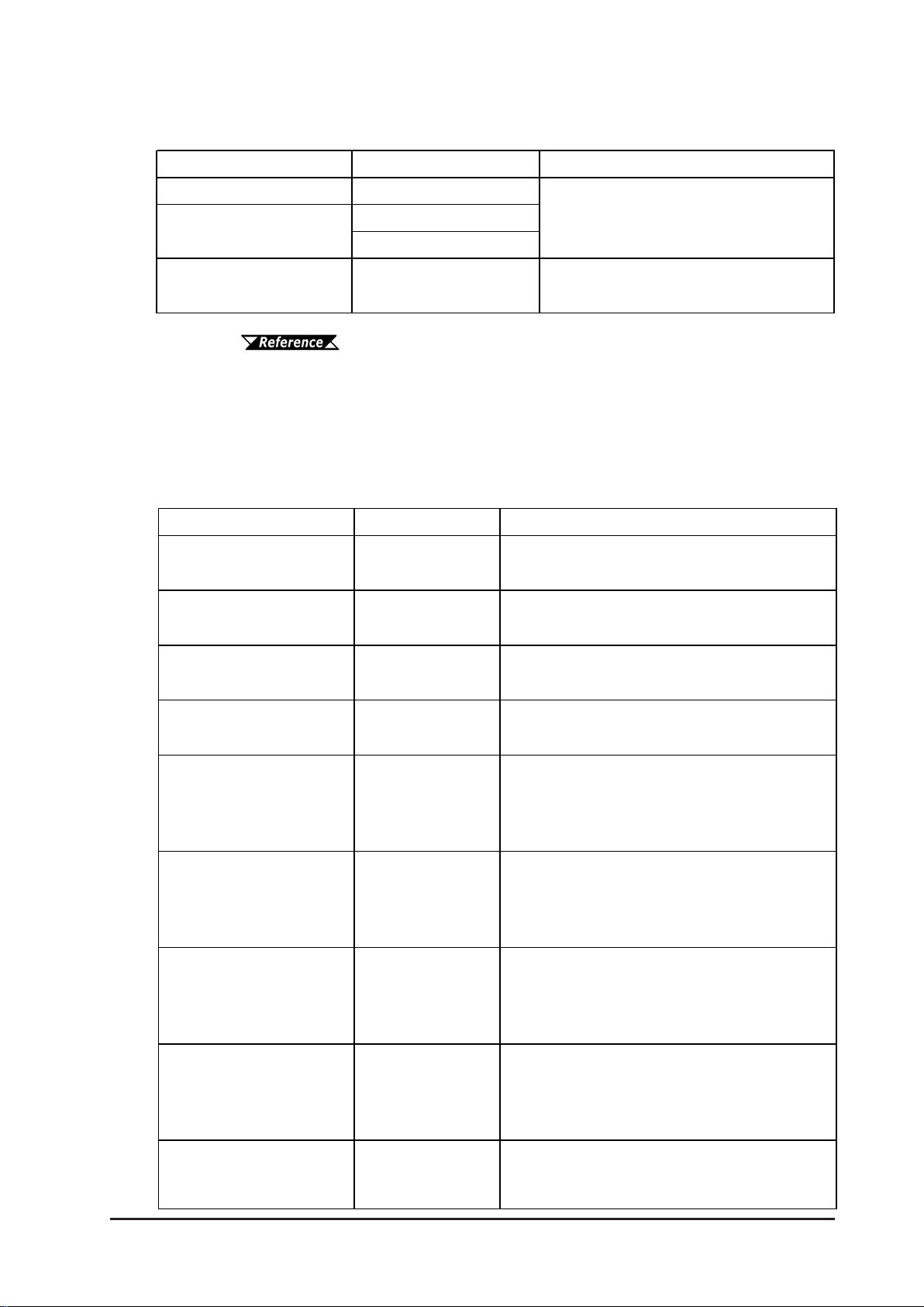
Documentation Conventions
The list below describes the documentation conventions used in this manual.
Symbol Meaning
Indicates important information or procedures that must be
followed for correct and risk-free software/device operation.
LT or
LT unit
LT Editor
C-Package
External
Dev ice
*1
LT Type A1/Type A2/Type B/Type B+/Type C,
LTC Type A1/Type B+
Indicates the LT Editor software.
Indicates Screen Creation software GP-PRO/PBIII and Logic
Program Development software Pro-Control Editor.
Indicates peripheral devices (such as Temperature Controllers,
Inverters, etc.), but does not include Flex Network and DIO units.
Provides useful or important supplemental information.
Provides useful or important supplemental information.
Cross-references to useful or important supplemental
information.
16
LT Series User Manual

Preface
Software Compatibility List
The LT Series of operator interfaces can use either of the following software
packages to create both screens and logic programs.
• GP-PRO/PBIII C-Package03 or later
• LT Editor
However, the LT color-type operator interfaces must use the GP-PRO/PBIII C-
Package03 or later software. LT Editor software cannot be used.
Also, for LT Type B+ Series units, the LT Editor version must be 1.04 or higher.
Please be sure to read the following table prior to creating your screens and logic
programs, as the software that can be used will vary depending on the type of unit.
Model Number LT Editor C-Package 03 or la ter
GLC150-BG41-XY32SK-24V
GLC150-SC41-XY32SK-24V
GLC150-BG41-XY32SC-24V
GLC150-BG41-FLEX-24V
GLC150-BG41-XY32KF-24V
GLC150-SC41-XY32KF-24V
GLC150-BG41-RSFL-24V
OO
XO
OO
OO
O
(Version 1.04 or later)
XO
OO
O
LT Series User Manual 17

Preface
Memo
18
LT Series User Manual

1. Prior to Operating the LT
2. System Design
3. Accessories
Chapter
1 Introduction
1.1 Prior to Operating the LT
Use the following steps when creating projects for the LT unit.
1. Preparation – Before using the LT, be sure that you have all required hard-
ware, and have read all specification, wiring, and installation
information.
Chapter 2 – “Specifications” and Chapter 3 – “Installation and
Wiring”
2. Design – Design your LT screens and create a logic program.
3. Install the LT Editor/C-Package – Install the LT Editor/C-Package software
in your PC.
LT Editor CD Jacket, C-Package CD Jacket
4. Develop Logic Program – Use the LT Editor/C-Package software to develop a
logic program and set the operation mode.
LT Editor Operation Manual – Logic Programming Guide, ProControl Editor Operation Manual/User Manual (included with the
C-Package software)
5. Create Screen / Run Screen Setup – Use the LT Editor software to set up the
screen and parts according to your screen design.
LT Editor Operation Manual – Screen Creation Guide, GP-PRO/
PBIII Operation Manual (included with the C-Package software)
6. Transfer Screen Data and Logic Pr ogram – Use the LT Editor/C-Package
software to transfer your screen data and logic program to the LT
unit.
LT Editor Operation Manual – Screen Creation Guide, GP-PRO/
PBIII Operation Manual (included with the C-Package software)
7. Monitor Logic Program – Use the LT Editor/C-Package software's monitor
feature to check that your logic program operates correctly.
LT Editor Operation Manual – Logic Programming Guide, ProControl Editor Operation Manual (included with the C-Package
software)
8. Initialize – Set up the LT unit's Initial Settings according to your operation needs.
Chapter 5 – “Initializing the LT”, LT Editor Device Connection
Manual and GP-PRO/PBIII Device/PLC Connection Manual
(included with the C-Package software)
9. Operation – Connect the LT to an external device and begin operation.
LT Editor Device Connection Manual, GP-PRO/PBIII Device/
PLC Connection Manual (included with the C-Package software)
Each LT Editor/C-Package manual referenced above is included with the LT Editor
software, and is also available as a PDF file on the CD-ROM.
LT Series User Manual 1–1

Chapter 1 – Introduction
1.2 System Design
1.2.1 System Design
There are five (5) L T series unit types: T ype A1, Type A2, T ype B, T ype B+ and T ype C.
LT Se ries
Name Model Description
LT Type A1 GLC150-BG41-XY32SK-24V
LTC Type A1 GLC150-SC41-XY32SK-24V
LT Type A2 GLC150-BG41-XY32SC-24V
LT Type B GLC150-BG41-FLEX-24V Flex Network I/F
LT Type B+ GLC150-BG41-XY32KF-24V
LTC Type B+ GLC150-SC 41-XY32KF-24V
LT Type C GLC150-BG41-RSFL-24V Flex Network I/F and SIO I/F
Stand-alone 32 point I/O System (Type A1/Type A2)
16-point Input Sink/Source and 16-point transistor
Output Sink type
16-point Input Sink/Source and 16-point transistor
Output Source ty pe
16-point Input Sink/Source and 16-point transistor
Output Sink, and Flex Network I/F type
The LT can independently control up to 32 external I/O units (DC 24V 16-point
Input/16-point Output).
LT
I/O Units
Flex Network System (Type B)
Connecting Flex Network units to the LT unit allows you to use the L T to control
remote I/O.
Flex Network I/O units are connected to the LT via the Flex Network I/F unit,
which is equipped with 2 channels — CH1 and CH2. Through these channels, the
LT can send identical communication data. Y ou can select either one of these
channels, or both, when sending communication data to the external I/O units.
Using a single channel enables you to send communication data to 31 I/O units via
one channel, and to 32 I/O units via the other channel. Therefore, using both
channels, the LT can communicate with a total of 63 Flex Network I/O units.
LT Series User Manual1–2

Chapter 1 – Introduction
LT
CH1
CH2
Flex
Network
Flex
Network
Units
For detailed information about the Flex Network, refer to
the Flex Network User Manual.
32 Point I/O + Flex Network System Design (Type B+)
The LT unit can independently control up to 32 I/O units. (DC24V Input 16 points/
Output 16 points Sink)
Connecting Flex Network I/O units to the LT allows the LT to control any remote I/O
unit. When connecting the I/O unit, two channels are available — CH1 and CH2. Each
channel outputs the same data and can be used for data communication.
When using a single channel, the maximum number of I/O units that can be
connected is 30, and when using a second channel, the number increases by 32,
for a total of 62 I/O units.
Since this unit’s 32 point I/O occupies one of the units in the Flex Network system, the total number of units available on Channel 1 is 31, and on Channel 2 is
32, for a total of 63 units.
Flex Network
LT
I/O Units
CH1
CH2
Flex Network
For detailed information about the Flex Network, refer to the Flex
Network User Manual.
LT Series User Manual 1–3

Chapter 1 – Introduction
Flex Network / SIO System Design (Type C)
Connecting Flex Network I/O units to the LT allows the LT to control any remote I/O
unit. When connecting the I/O unit, two channels are available — CH1 and CH2. Each
channel outputs the same data and can be used for data communication.
When using a single channel, the maximum number of I/O units that can be
connected is 31, and when using a second channel, the number increases by 32,
for a total of 63 I/O units.
The LT unit's serial interface allows you to connect to external devices such as
temperature controllers or inverters.
SIO
LT
Flex Network
CH1
CH2
Flex Network
Temperature Controller,
Inverter, etc.
For detailed information about the Flex Network, refer to the Flex
Network User Manual.
For information about external devices, refer to the LT Editor Device Connection Manual (included with the LT Editor softwar e), GPPRO/PBIII Device/PLC Connection Manual (included with the C-
Package software) .
LT Series User Manual1–4

Chapter 1 – Introduction
1.2.2 Product Lineup
The following diagram represents the main selection of devices connectable to the
LT.
Screen Editing Environment
LT Operating Environment
c
Data Transfer Cable
GPW-CB02
USB Data
Transfer Cable
GPW-CB03
Bar Code Reader
(limited to tested types)
DIO Connector
GLC100-DIOCN01
d
DIO Connector
GLC-DIOCN02
*3
*4
LT Editor Integrated
Development Software
Personal
Computer
*1
Conversion Cable
(user-created)
DIO Cable
Flat Cable
*2
Printer
(Commercially available
type)
i
I/O Units,
Lamps,
LEDs,
Sensors,
Switches,
etc.
f
DIO Cable (w/connector)
CGP070-ID11-M (3.5m)
GLC000-DIOCB11-MS (3.5m)
e
Flex Network Communication Cable
FN-CABLE2010-31-MS (10m)
FN-CABLE2050-31-MS (50m)
FN-CABLE2200-31-MS (200m)
RS-422 Connector
Terminal Adapter
GP070-CN10-0
RS-232C Cable
GP410-IS00-0
RS-422 Cable
GP230-IS11-0
GP230-IS12-0
(for Multi-link cable)
*5
*5
*5
*5
h
Flex Network
units (I/O,
Analog, etc.)
g
External Devices
(Temperature
Controllers,
Inverters, etc.)
*6
LT Series User Manual 1–5

Chapter 1 – Introduction
1 For the range of compatible PCs, refer to the
2 The software that can be used will vary depending on the type of unit.
3 Software version limitations apply.
4 See Page 1-7 for recommended units.
5 Certain types and models of external devices cannot be connected.
6 For information about compatible external device types, refer to the
LT Editor CD Jacket (included with the LT Editor software),
C-Package CD Jacket
Software Compatibility List
For details, USB Data Transfer Cable Installation Guide.
LT Editor Device Connection Manual (included with the LT Editor
software), GP-PRO/PBIII Device/PLC Connection Manual (in-
cluded with the C-Package software)
LT Editor Device Connection Manual (included with the LT Editor
software), GP-PRO/PBIII Device/PLC Connection Manual (included with the C-Package software)
LT Interfaces
c Tool Connector
d I/O Connector (Type A1/Type A2/Type B+)
e Flex Network Interface (Type B/Type B+/Type C)
f Serial Interface (Type C)
External Device Interface (for Temperature Controllers, Inverters, etc.)
g RS-232C Port
h RS-422 Port
Personal Computer Interfaces
i Printer Interface
LT Series User Manual1–6

Chapter 1 – Introduction
Recommended Units
The following tables list I/O devices that have been confirmed to be compatible
with the LT. If you connect a device other than those listed below, be sure to
confirm that the connection functions correctly using an actual unit.
Recommended units are subject to change without notice.
Bar code readers (Connected to Tool Connector)
NEC Infrontia
*1 Be sure to use the Y cable included with the unit and connect it between the LT unit
and a bar code reader. Data cannot be read correctly, if a non-"Y" cable is used, or if
the bar code reader is connected directly to the LT unit.
*2 The following settings must be entered prior to using the bar code reader with a LT
unit.
1) Set the CAPS.
2) Add the Carriage Return (CR) in the Postamble's settings.
For the details about these settings, please refer to the Installation Guide included
with the bar code reader unit.
BCK5435-S TA Touch Scanner (Read Widt h: 56mm)
BCK5535-S TA Touch Scanner (Read Widt h: 85mm)
*1*2
*1*2
LT Series User Manual 1–7

Chapter 1 – Introduction
Power/Common: AWG#22/Approved for 7A current (green)
wire marking cover in the description.
1.3 Accessories
The following items are optional LT products (sold separately).
Available Software*
Product Nam e Mode l No. Description
LT Editor
C-Package 03 or later
GLCLT-ED01W-V**
GPPRO-CNT03W-P03
1
Sof t ware us ed t o creat e t he LT unit’s screen data and t o
dev elop a logic program.
1 The software that can be used will vary depending on the type of unit.
Software Compatibility List
Tool Connector
Product Name Model No. Description
Data Transfer Cable
USB Data Transfer
*1
Cable
GPW-CB02
GPW-CB03
Connects the LT to a PC; t rans f er s screen dat a and user
program(s).
1 Software version limitations apply.
For details, USB Data Transfer Cable Installation Guide.
I/O Interfaces (Type A1/Type A2/Type B+)
Product Name Model No. Description
Connector (must be soldered) and connector cover, including five
GLC100-DIOCN01
DIO Conne ctor
GLC-DIOCN02
CGP070-ID11-M
DIO Cable
GLC000-DIOCB11-MS
Flex Network Interface (Type B/Type B+/Type C)
Product Name Model No. De scription
pieces of FCN-361J040-AU (connector) and FCN-360C040-B
(connector cover). Manufactured by Fujitsu Component Corp.
Crimp connector for ribbon cable. (5/set)
Fujitsu Component Ltd.
FCN-367J040-AU/F
3.5m cable that includes Fujitsu Component Ltd.'s pre-attached
connector (FCN- 361J040-AU) and connector cover FCN360C040-B.
Power/Common: AWG#22/Approved for 7A current (red/black)
I/O Signal: AWG#24/Approved for 5A current (yellow/green)
Includes wire ma rking cover ( n o t terminated)
3.5m cable that includes Fujitsu Component Ltd.'s pre-attached
connector (FCN- 361J040-AU) and connector cover FCN360C040-B.
I/O Signal: AWG#24/Approved for 5A current (green)
Includes wire ma rking cover ( n o t terminated)
The same reference number as the connector No. is used for the
Flex Network
Communication Cable
FA -CABLE2010- 31-MS (10m)
FN-CABLE2050-31-MS (50m)
FN-CABLE2200-31-MS (200m)
Connect GLC/LT units wit h Flex Net wor k units.
LT Series User Manual1–8
Chapter 1 – Introduction
Serial Interfaces (Type C)
Product Name Model No. Description
RS-232C ca b l e
RS-422 ca b le
RS-422 ca b le Connector
Term inal Block Conversi on
Adapter
*1
*1
*1
1 For detailed information about the range of connectable external
Flex Network I/O Units (Type B/Type B+/Type C)
GP410-IS00-0
GP230-IS11-0
GP230-I S12- 0 ( f or Multi-link )
GP070-CN10-0
Int er f ace cable between the external device and
the LT.
Conversion adapter conv er ts serial data to the RS422 for mat.
devices, refer to the LT Editor Device Connection Manual (included
with the LT Editor software) and the GP-PRO/PBIII Device/PLC
Connection Manual (included with the C-Package software).
Product Name Model No. Description
Flex Network 16- P oint Input
Sink Source Type I/O Unit
Flex Network 32- P oint Input
Sink Source Type I/O Unit
Flex Netw ork 16-Point Output
Sink Ty pe I/O Unit
Flex Netw ork 16-Point Output
Sourc e Ty pe I/O Unit
Flex Network 8-P oint Input
Sink Source / 8-Point
Transis t or Out put Sink Type
I/ O U nit
Flex Network 16- P oint Input
Sink Source / 16 - Point
Transis t or Out put Sink Type
I/ O U nit
Flex Network 16- P oint Input
Sink Source/16-Point
Transis t or Out put Sink Type
I/ O U nit
FN-X16T S41
FN-X32T S41
FN-Y16SK41 16-point output sink I/O Unit.
FN-Y16SC41 16-point output source I/ O Unit .
FN-XY08TS41
FN-XY16SK41
FN-XY16SC41
16-point s ink/source shared I/O Unit . DC24V input signal
can be connected.
32-point s ink- s ource shared I /O Unit. DC24V input signal
can be connected.
8-point input sink-source and 8-point t r ansis t or out put sink
mixed I/O unit . Both DC24V input signals and DC24V
output ( load current: 200mA max. ) devices can be
connected.
16-point input sink-source and 16-point t r ans ist or out put
sink mixed I/ O unit . B ot h DC24V input signals and DC24V
output ( load current: 200mA max. / 1. 6A/common) dev ices
can be connected.
16-point input sink-source and 16-point t r ans ist or out put
source mixed I/O unit . B ot h DC24V input signals and
DC24V output (load current: 200mA max./ 1.6A/ common)
dev ices can be connected.
Flex Network 32- P oint Input
Sink Source / 32 - Point
Transis t or Out put Sink Type
I/ O U nit
Flex Netw ork 8-Point Relay
Output / 1 Common Ty pe I/O
Unit
FN-XY32SKS41
FN-Y08RL41
32-point input sink-source and 32-point t r ans ist or out put
sink mixed I/ O unit . B ot h DC24V input signals and DC24V
output ( load current: 200mA max. / 1. 6A/common) dev ices
can be connected.
8-point r elay output ( 1 common)I/O Unit. Up to AC240V (1A)
load current can be connected.
LT Series User Manual 1–9

Chapter 1 – Introduction
Flex Network
Single-Ax is Motor Driver
Connects the Flex Net wor k single- axis positioning unit and
Installation Fastener
s
Single Ax is Teaching Loader
Connects the S ingle- Axis Positioning unit to the S ingle-
DIO Conne c t or
Connectors (terminal screws) for " FN-X Y32SKS41", "FN-
Flex Netw ork 2-Channel
Conv er t s 2- channnel analog signals to digit al s ignals at
Flex Netw ork 2-Channel
Conv er t s 2channel 12-bit digit al s ignal t o analog signal
Flex Netw ork 4-Channel
Conv er t s 4- channnel analog signals to digit al s ignals at
Flex Netw ork 4-Channel
Conv er t s 4- channel 12-bit digit al signal to analog signal
Analog Units
Product Name Model No. Description
Analog/Digital Conv e r s ion
Digita l/Analog Conve rs ion
Analog/Digital Conv e r s ion
Digita l/Analog Conve rs ion
Positioning Units
Product Name Model No. Description
Single-Axis Positioning Unit
Flex Network
Teaching Loader for SingleAxis Posit ioning Unit
High-Speed Counter Unit
Product Name Model No. Description
Flex Network
High Spe e d Counter Unit
FN-AD02AH41
FN-DA02AH41
FN-AD04AH11
FN-DA04AH11
FN-PC10SK41
FN-PC10LD41
FN-HC10SK41
12-bit r es olut ion.
and sends output.
12-bit r es olut ion.
and sends output.
Both of this unit and GLC/LT can store positioni ng data. Motor
driver connection cable(FN-PC10CB01) is required.
Programmer for Single-Axis Positioning Uni t. Allows entry, editing
and operation checking of high-precision positioning data
(5m cable included)
High performance High-Speed counter that can easily
change counter input t ypes. Can create bot h a wide range
of dat a and cam output.
Optional Items
Item M ode l No. Description
Screen Protection Sheet
(5 sheet s / s et )
Connec t ion C a ble
Optional Maintenance Items
GP37W2-DF00
FN-PC10CB01 (1m)
The following items are included in the L T unit’s packing box, and are also sold separately .
Product Name Model No. Description
(4 fas t ener s / s et )
Installation Gasket GP37W2-WP00-MS
Flex Network
Comm unic a t ion C a ble
Connector
GP070-AT01 Fasteners to attach the LT to a panel.
FN-IFCN01
Disposable protective and dirt-res istant sheet for the LT
unit' s s creen. The LT unit's t ouch panel can be used with
this cov er s heet attached.
the ser vo and stepping dr ivers.
Provides a moisture- res is t ant s eal when ins t alling t he LT.
Same as the seal included in the LT unit's or iginal
equipment package.
Connector is at t ached to t he Flex Net wor k I / F unit . E nable
the connection of t he Flex Network Communication
Cable.
Cable
(S pr ing Type )
FN-LD10CBL (5m)
GLC-DIOCN03
A x is Teaching Loader.
XY32SCS41" unit s . E as y-to-us e s pring- clamp ty pe.
LT Series User Manual1–10
1. General Specifications
2. Functional Specifications
3. Interface Specifications
Chapter
2 Specifications
2.1 General Specifications
2.1.1 Electrical
4. Part Names and Functions
5. Dimensions
Rated Voltage
Voltage Supply Range
Allowable Voltage Drop
Power Consumption
In-Rush Current
Voltage Endurance
Insula tion Resista nce
DC 24V
DC 20.4V to DC 28.8V
10 ms or less
20 W or less
30 A or less
A C 1000V at 10 mA for 1 minute (between VCC and FG terminals)
DC 500V at 20 MΩ or higher (between V CC and FG terminals)
2–1LT Series User Manual
 Loading...