

Page 1

/77070
,QVWDOODWLRQ*XLGH
/77070
ඞହછ
Page 2

English
The information provided in this documentation contains general descriptions and/or
technical characteristics of the performance of the products contained herein. This
documentation is not intended as a substitute for and is not to be used for determining
suitability or reliability of these products for specific user applications. It is the duty of any
such user or integrator to perform the appropriate and complete risk analysis, evaluation
and testing of the products with respect to the relevant specific application or use thereof.
Neither Pro-face nor any of its affiliates or subsidiaries shall be responsible or liable for
misuse of the information that is contained herein. If you have any suggestions for
improvements or amendments or have found errors in this publication, please notify us.
No part of this document may be reproduced in any form or by any means, electronic or
mechanical, including photocopying, without express written permission of Pro-face.
All pertinent state, regional, and local safety regulations must be observed when installing
and using this product. For reasons of safety and to help ensure compliance with
documented system data, only the manufacturer should perform repairs to components.
When devices are used for applications with technical safety requirements, the relevant
instructions must be followed.
Failure to use Pro-face software or approved software with our hardware products may
result in injury, harm, or improper operating results.
Failure to observe this information can result in injury or equipment damage.
Copyright © 2013.12 Digital Electronics Corporation. All Rights Reserved.
2
Page 3

LT-4201TM/4301TM Installation Guide
Safety Information
Important Information
NOTICE
Read these instructions carefully, and look at the equipment to become familiar with the
device before trying to install, operate, or maintain it. The following special messages may
appear throughout this documentation or on the equipment to warn of potential hazards or
to call attention to information that clarifies or simplifies a procedure.
!
English
3
Page 4

PLEASE NOTE
English
Electrical equipment should be installed, operated, serviced, and maintained only by
qualified personnel. No responsibility is assumed by Pro-face for any consequences arising
out of the use of this material.
A qualified person is one who has skills and knowledge related to the construction and
operation of electrical equipment and its installation, and has received safety training to
recognize and avoid the hazards involved.
4
Page 5

LT-4201TM/4301TM Installation Guide
About the Book
Document Scope
Thank you for purchasing Pro-face's LT4000 Series Graphic Logic Controller Interface
(Hereafter referred to as the "LT").
Document Scope
This guide describes how to install the LT-4201TM/4301TM. For more detailed information,
refer to the manuals indicated below.
Global Code
A global code is assigned to every Pro-face product as a universal model number.
For more information on product models and their matching global codes, please refer to
the following URL:
http://www.pro-face.com/product/globalcode.html
Validity Note
This documentation is valid for GP-Pro EX V4.0 or later.
The characteristics presented in this manual should be the same as those that appear
online. In line with our policy of constant improvement we may revise content over time to
improve clarity and accuracy. In the event that you see a difference between the manual
and online information, use the online information as your reference.
English
Related Documents
Title of Documentation Reference Number
GP-Pro EX Reference Manual
Maintenance/Troubleshooting Guide
GP-Pro EX Device/PLC Connection Manual System configuration of connected devices (PLCs
LT-4201TM/4301TM Hardware Manual Specifications, dimensions, accessories, system
• Troubleshooting
Help for solving problems.
• Maintenance
Details on the LT unit’s Offline Mode
and other devices), communication settings
examples, connection wiring diagram, and other
details.
design, standards, and other details.
You can download these technical publications and other technical information from our
website "Otasuke Pro!" at http://www.pro-face.com/otasuke/.
5
Page 6

Product Related Information
English
DANGER
HAZARD OF ELECTRIC SHOCK, EXPLOSION OR ARC FLASH
Disconnect all power from all equipment including connected devices prior to
removing any covers or doors, or installing or removing any accessories, hardware,
cables, or wires except under the specific conditions specified in the appropriate
hardware guide for this equipment.
Always use a properly rated voltage sensing device to confirm the power is off where
and when indicated.
Replace and secure all covers, accessories, hardware, cables, and wires and confirm
that a proper ground connection exists before applying power to the unit.
Use only the specified voltage when operating this equipment and any associated
products.
Failure to follow these instructions will result in death or serious injury.
This equipment has been designed to operate outside of any hazardous location. Only
install this equipment in zones known to be free of a hazardous atmosphere.
DANGER
POTENTIAL FOR EXPLOSION
Install and use this equipment in non-hazardous locations only.
Failure to follow these instructions will result in death or serious injury.
6
Page 7

LT-4201TM/4301TM Installation Guide
WARNING
LOSS OF CONTROL
Consider the potential failure modes of control paths in the machine control system
design, such as:
The possibility of backlight failure,
Unanticipated link transmission delays or failures,
The operator being unable to control the machine,
The operator making errors in the control of the machine.
Design outside the LT operations such as emergency stop, safety circuits, interlocks
that operate with opposing actions such as clockwise/counterclockwise rotation, and
circuits that prevent machine damage with positioning limits on top, bottom, and
movement.
For important operations handled by switches, design your system to use a separate
hardware device. This is to reduce the occurrence of incorrect outputs or malfunctions.
Observe all accident prevention regulations and local safety guidelines.
Test individually and thoroughly each implementation of the equipment for correct
operation before service.
Failure to follow these instructions can result in death, serious injury, or equipment
damage.
1
For additional information, refer to NEMA ICS 1.1 (latest edition), "Safety Guidelines for
the Application, Installation, and Maintenance of Solid State Control" and to NEMA ICS 7.1
(latest edition), "Safety Standards for Construction and Guide for Selection, Installation and
Operation of Adjustable-Speed Drive Systems" or their equivalent governing your particular
location.
1
English
7
Page 8

English
8
Page 9

LT-4201TM/4301TM Ins tallation Guide
LT-4201TM/4301TM
LT-4201TM/4301TM Installation Guide
LT-4201TM/4301TM of P anels
LT-4201TM/4301TM of Panels
LT Range
Thank you for purchasing Pro-face’s LT4000 Series unit (hereafter referred to as the “LT”):
English
Series Model Names Models Digital
Input
LT4000
Series
LT-4201TM
(Modular Type
DIO)
LT-4301TM
(Modular Type
DIO)
LT-4000M
(Modular Type
PFXLM4201TADDC
PFXLM4201TADDK
PFXLM4301TADDC
PFXLM4301TADDK
PFXLM4B01DDC
PFXLM4B01DDK
20 Points
Standard
Input
(2 Points
for Fast
Input)
Digital
Output
10 Points
Standard
Output
and
2 Points
Fast
Output
Analog Input Analog
Output
None None 3.5 in.
DIO)
LT-4201TM
(Modular Type
Analog)
LT-4301TM
(Modular Type
Analog)
LT-4000M
(Modular Type
PFXLM4201TADAC
PFXLM4201TADAK
PFXLM4301TADAC
PFXLM4301TADAK
PFXLM4B01DAC
PFXLM4B01DAK
12 Points
Standard
Input
(2 Points
for Fast
Input)
6 Points
Standard
Output
and
2 Points
Fast
Output
2 ch analog
inputs (13-bit)
and 2 ch
analog inputs
(16-bit) for
Thermocouple
2ch
analog
outputs
(12-bit)
Analog)
3.5 inch
PFXXM4200TP None 3.5 in.
display
module
5.7 inch
PFXXM4300TP None 5.7 in.
display
module
NOTE: Fast Input and Fast Output are generic terms for the following functions:
Fast Input: High-speed Counter Input and Pulse Catch Input.
Fast Output: Pulse Output, PWM Output and High-speed Counter Synchronize Output.
Screen
Size
5.7 in.
None
3.5 in.
5.7 in.
None
9
Page 10

LT-4201TM/4301TM
Display Module/Rear Module Separation Cable Range
English
Reference Cable Length
PFXZXMADSM31 3 m (9.84 ft.)
PFXZXMADSM51 5 m (14.40 ft.)
NOTE: The outer diameter of the cable is 8 mm (0.13 in.). To assemble this product, you need 20 mm
(0.78 in.) more space to bend the cable in the end of the rubber.
Agency Certifications for LT Unit
For information on Standards and Regulations, such as certified models and certificates,
see the marking on the product or the following link:
http://www.pro-face.com/worldwide.html
LT unit is manufactured in accordance with UL 508 and CSA C22.2 n° 142 for industrial
control equipment.
For use on a flat surface of a Type 1, Type 4X (indoor use only) enclosure.
Hazardous Substances
This product is a device for use in factory systems. When using this product in a system,
the system should comply with the following standards in regards to the installation
environment and handling:
WEEE, Directive 2012/19/EU
RoHS, Directives 2011/65/EU
RoHS China, Standard SJ/T 11363-2006
REACH regulation EC 1907/2006
CE Markings
This product conforms to the necessary requirements of the following Directives for
applying the CE label:
2006/95/EC Low Voltage Directive
2004/108/EC EMC Directive
This conformity is based on compliance with IEC61131-2.
10
Page 11

LT-4201TM/4301TM Installation Guide
CAUTION
ENVIRONMENTAL HAZARDS TO THE EQUIPMENT
Allow the device to reach the surrounding air temperature, not exceeding 50 ° C
(122 ° F), before turning the device on.
Do not turn on the device if condensation has occurred inside the device. After it is
completely dry again, the device may be turned on.
Do not expose the device to direct sunlight.
Do not obstruct the vents in the device casing.
Remove any dust from the device before turning it on.
Ensure that the cable installation fasteners are not damaged. Replace them, if
necessary.
Mount the device into an enclosure that meets the IP65 level of protection.
Failure to follow these instructions can result in injury or equipment damage.
WARNING
RISK OF EXPLOSION IN HAZARDOUS LOCATIONS
Verify that the power, input, and output (I/O) wiring are in accordance with Class I,
Division 2 wiring methods.
Do not substitute components that may impair compliance to Class I, Division 2.
Do not connect or disconnect equipment unless power has been switched off or the
area is known to be non-hazardous.
Securely lock externally connected units and each interface before turning on the
power supply.
Do not, connect, or disconnect USB cable unless area is known to be non-hazardous.
Potential electrostatic charging hazard: wipe the front panel of the terminal with a
damp cloth before turning ON.
Failure to follow these instructions can result in death, serious injury, or equipment
damage.
English
Interfaces are: COM1, Ethernet, USB1 and USB2.
WARNING
RISK OF EXPLOSION IN HAZARDOUS LOCATIONS
Do not disconnect while circuit is live.
Potential electrostatic charging hazard: wipe the front panel of the terminal with a
damp cloth before turning ON.
Failure to follow these instructions can result in death, serious injury, or equipment
damage.
11
Page 12

LT-4201TM/4301TM
Package Contents
English
Verify that all items shown in the figure are present in your package:
Legend Description Package Type
LT Unit Display Module Rear Module
1 Display module Yes Yes No
2 Rear module Yes No Yes
3 Display installation nut
(attached to the display
module)
4 Anti-rotation tee Yes Yes No
5 Socket wrench Yes No No
6 USB clamp type A Yes No Yes
7 DC power supply connector Yes No Yes
8 I/O connector 15-pin 2 No 2
9 I/O connector 6-pin 2 No 2
10 LT-4201TM/4301TM
Installation Guide
11 Warning / Caution
information
Yes Yes No
Yes No Yes
Yes
12
Page 13

Handling the LCD
LT-4201TM/4301TM Installation Guide
CAUTION
SERIOUS EYE AND SKIN INJURY
The liquid present in the LCD contains an irritant:
Avoid direct skin contact with the liquid.
Wear gloves when you handle a broken or leaking unit.
Do not use sharp objects or tools in the vicinity of the LCD touch panel.
Handle the Panel carefully to prevent puncture, bursting, or cracking of the Panel
material.
Failure to follow these instructions can result in injury or equipment damage.
If the Panel is damaged and any liquid comes in contact with your skin, immediately rinse
the area with running water for at least 15 min.
If the liquid gets in your eyes, immediately rinse your eyes with running water for at least
15 minutes and consult a doctor.
Product Label Sticker
You can identify the product version (PV) and the revision level (RL) from the product label
on the panel.
The following diagram is a representation of a typical label:
English
LT4200/4300 Series model which unit’s version number (PV ) is 02 or later can also be used
as Rear Module.
13
Page 14
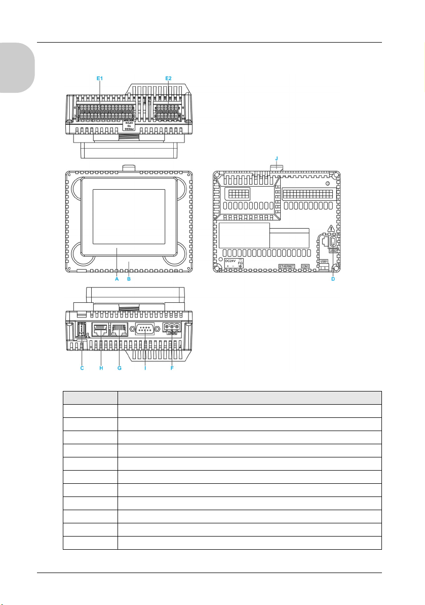
LT-4201TM/4301TM
LT-4201TM/4301TM and Rear Module Parts Identification:
English
Part Description
A Display module
B Rear module
C USB (type A) interface connector (USB1)
D USB (mini B) interface connector (USB2)
E1 I/O terminal block 1
E2 I/O terminal block 2
F DC power supply connector
G Ethernet interface
H Serial link (RS-232C/485)
I CANopen interface
J Yellow button lock
14
Page 15

LT-4201TM/4301TM Ins tallation Guide
LT-4201TM/4301TM Installation Guide
Installation
Installation
Inserting the Display Module with an Anti-Rotation Tee
Create a panel cut-out and insert the display module into the panel from the front. The figure
shows the panel cut-out:
English
Dimensions
A B (1) B (2) C D
22.50
(0.88
0/-0.30
0/-0.01
mm
in.)
1.5...6 mm
(0.06...0.23 in.)
3...6 mm
(0.11...0.23 in.)
0/-0.20
30
(1.18
mm
0/-0.0007
in.)
0/-0.20
4
(0.15
mm
0/-0.007
in.)
(1) Steel sheet
(2) Glass fiber reinforced plastics (minimum GF30)
NOTE: The display module supports a rotating torque of 6 N•m (53.10 lb-in).
Without the tee option, the display module supports a rotating torque of 2.5 N•m (22.12 lbin).
15
Page 16
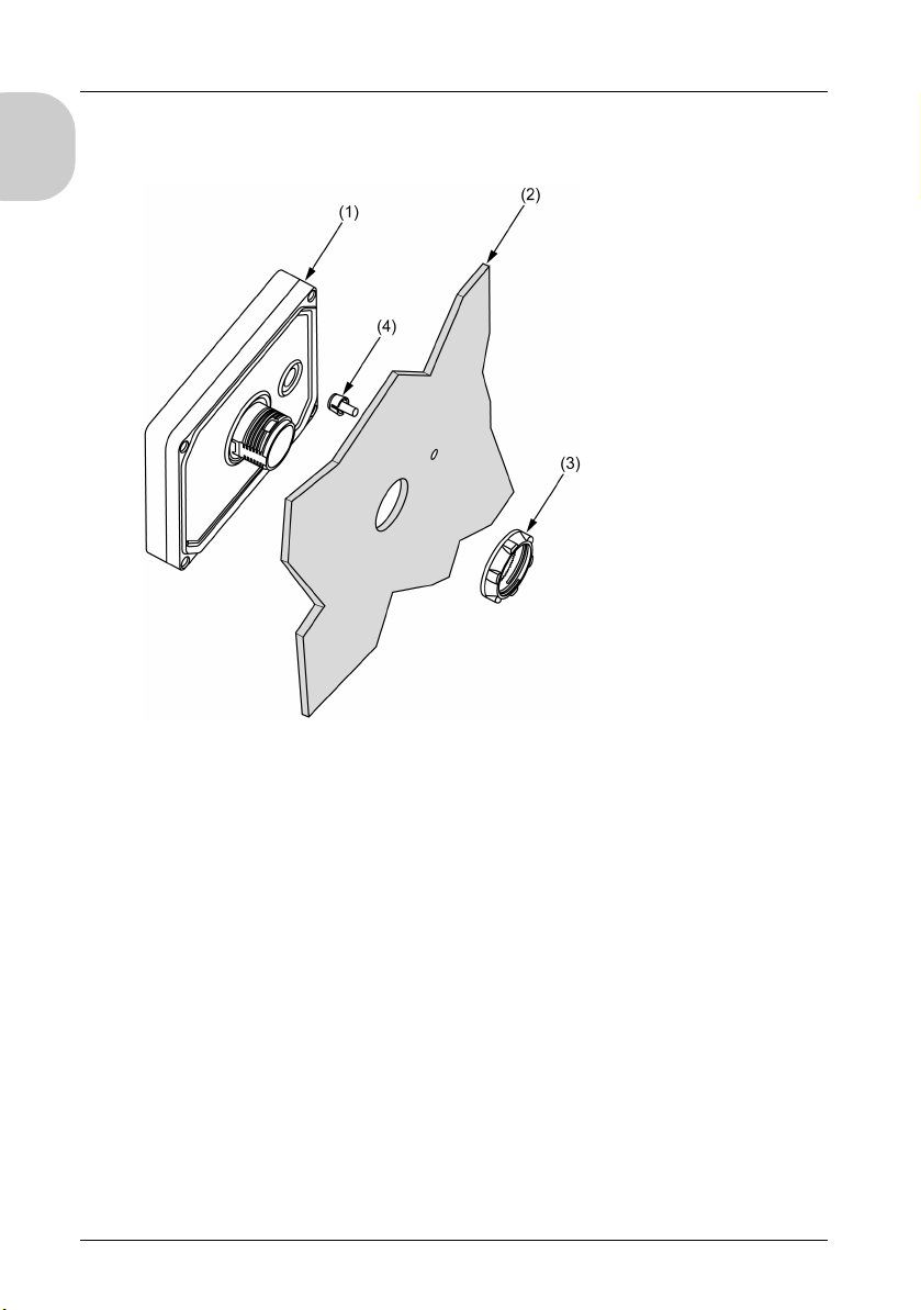
Installing the LT Display
The figure shows the assembly:
English
(1) Display module
(2) Panel
(3) Display installation nut
(4) Anti-rotation tee
Installing the LT Display Module with Spacer
The spacer supplied in the accessory kit PFXZGMAK1 (sold separately), allows mounting
the product on a:
steel sheet support with a thickness between 1 and 1.5 mm (0.039 in. and 0.059 in.)
plastic support with a thickness between 1 and 3 mm (0.039 in. and 0.118 in.)
glass fiber reinforced plastic with a thickness between 2 and 3 mm (0.078 in. and
0.118 in.)
16
Page 17
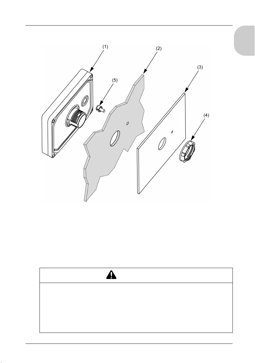
The figure shows the assembly with the Panel spacer:
LT-4201TM/4301TM Installation Guide
English
(1) Display module
(2) Panel
(3) Spacer
(4) Display installation nut
(5) Anti-rotation tee
Installation of the LT Unit
In order to correctly run an application on the LT, both the display module and the rear
module must be connected.
WARNING
EXPLOSION HAZARD
Do not connect or disconnect while circuit is live.
Potential electrostatic charging hazard: wipe the front panel of the terminal with a
damp cloth before turning ON.
Refer to Hardware Manual for instructions
Failure to follow these instructions can result in death, serious injury, or equipment
damage.
17
Page 18
English
If you power up the rear module without connecting the display module, the logic controller
does not start and all outputs remain in the initial state. The power must be off when you
connect the 2 modules.
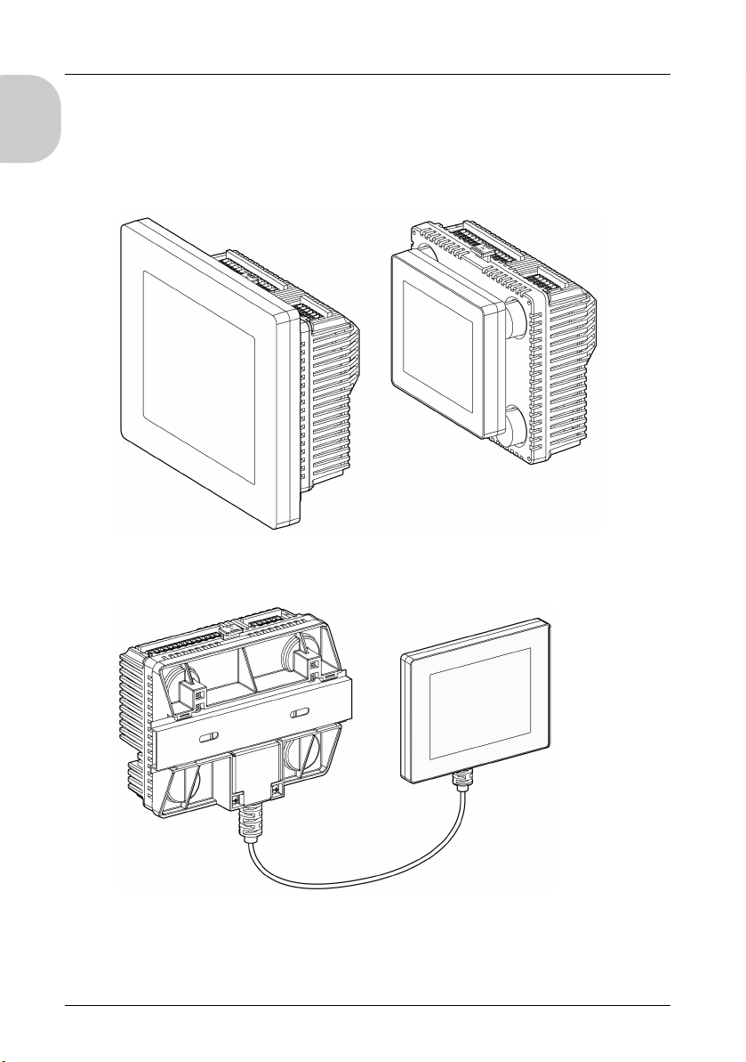
There are 2 ways to install the LT.
Installing the LT on the panel:
Installing the rear module on a DIN rail with a display module/rear module separation
cable:
18
Page 19
LT-4201TM/4301TM Installation Guide
Setup Procedure
Mount the unit in an enclosure that provides a clean, dry, robust, and controlled
environment (IP65 enclosure or UL508 4x if indoors).
Before installing the LT Unit verify that:
The installation panel or cabinet surface is flat (planarity tolerance: 0.5 mm (0.019 in.)),
in good condition and has no jagged edges. Metal reinforcing strips may be attached to
the inside of the panel, near the panel cut-out, to increase the rigidity.
The panel should be designed to avoid any induced vibration resonance on the rear
module exceeding a punctual factor of 10 and to avoid any induced permanent vibration
resonance.
To reduce the resonance use the panel adaptor accessory.
The ambient operating temperature and the ambient humidity are within their specified
ranges:
Horizontal installation: 0...50 ° C (32...122 ° F)
Vertical installation:0...40 ° C (32...104 ° F)
Relative humidity: 5...85% w/o condensation (non-condensing, wet bulb
Temperature 39 ° C (102.2 °F) or less)
The heat from surrounding equipment does not cause the unit to exceed its specified
operating temperature.
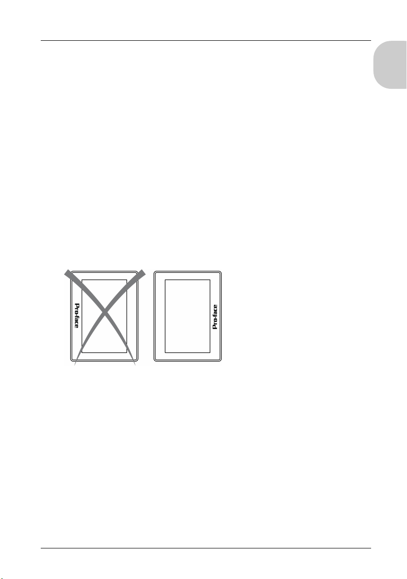
When installing the display in a vertical position (portrait view), the logo on the display
face must be on the right side to keep the power connector at the top:
English
NOTE: For use in Pollution Degree 2 environments.
19
Page 20
English
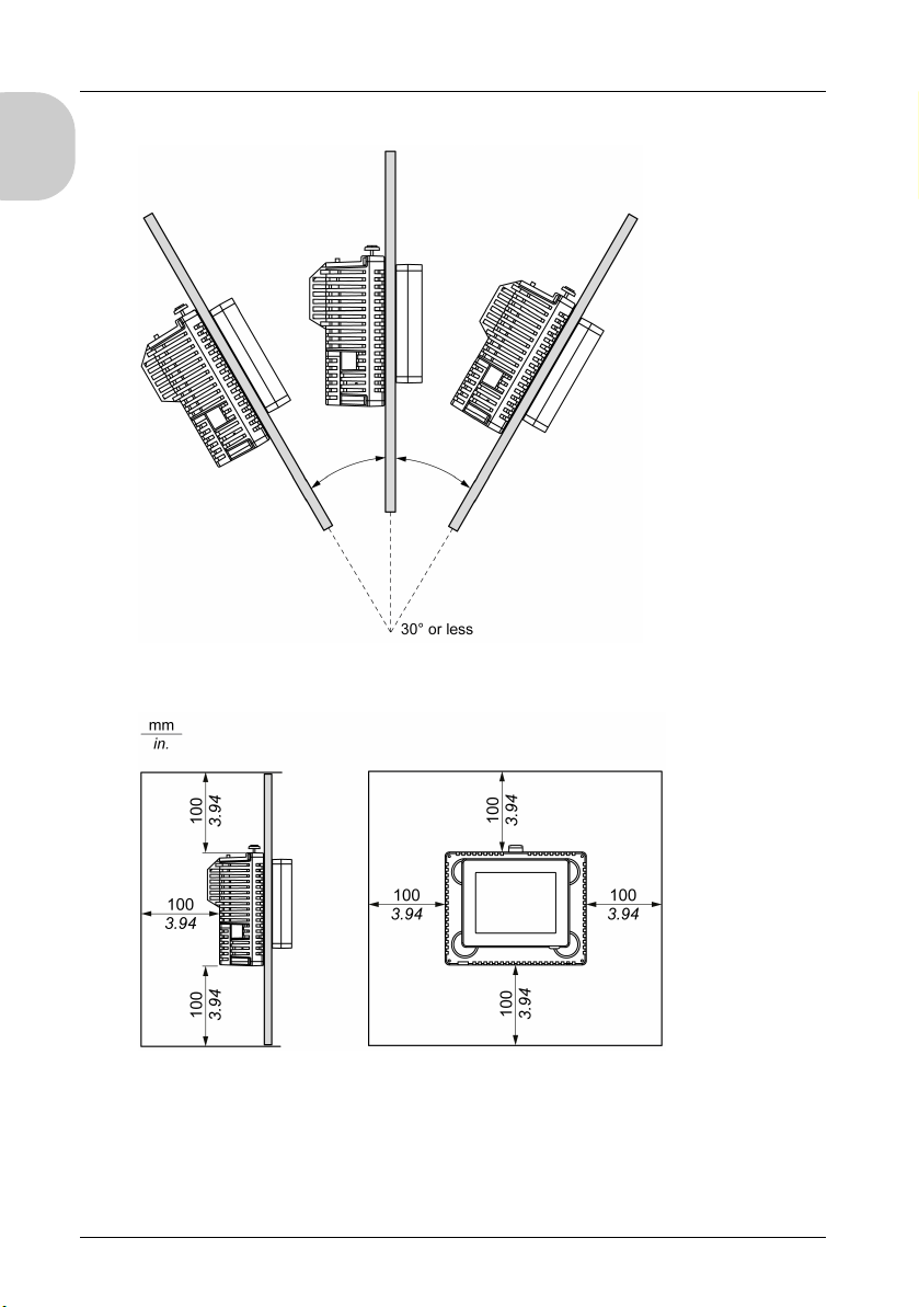
The panel face is not inclined more than 30° when installing the unit in a slanted panel:
The power plug is positioned vertically when the unit is vertically installed.
The unit is at least 100 mm (3.94 in.) away from adjacent structures and other
equipment for easier maintenance, operation, and improved ventilation:
20
Page 21
LT-4201TM/4301TM Installation Guide
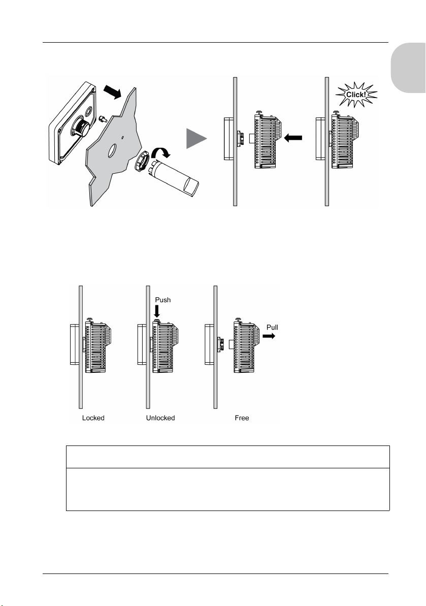
The figure shows how to install the panel with the rear module:
1 Create the correct sized holes required to install the unit, using the panel cut-out dimension.
2 Insert the display module (with the tee, if required) into the panel hole (use a torque between 1.2
and 2 N•m (10.62 lb-in and 17.70 lb-in) to screw the nut with the tightening wrench).
3 Insert and push the rear module until it locks into place.
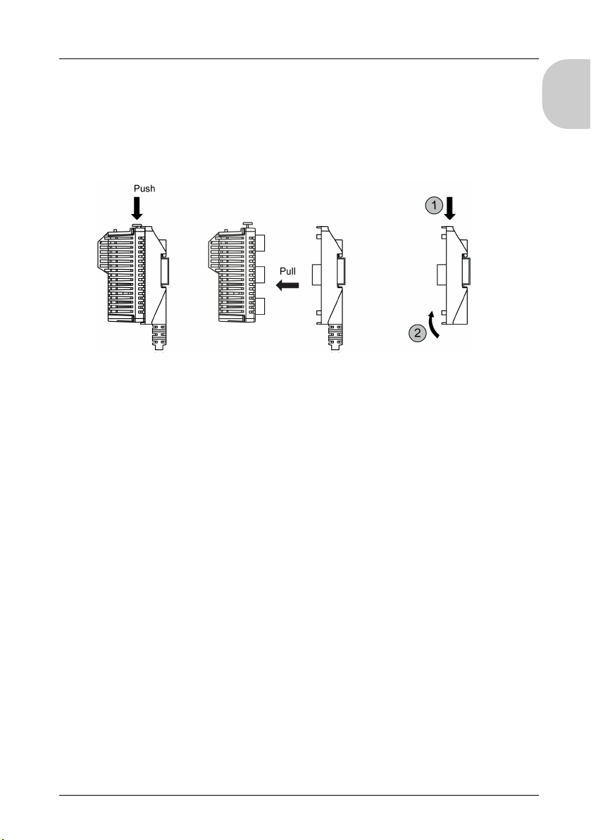
To remove the rear module, push the yellow button to unlock it, and then pull out the rear
module:
English
NOTICE
EQUIPMENT DAMAGE
Be sure to remove the rear module from the display module without twisting.
Failure to follow these instructions can result in equipment damage.
21
Page 22
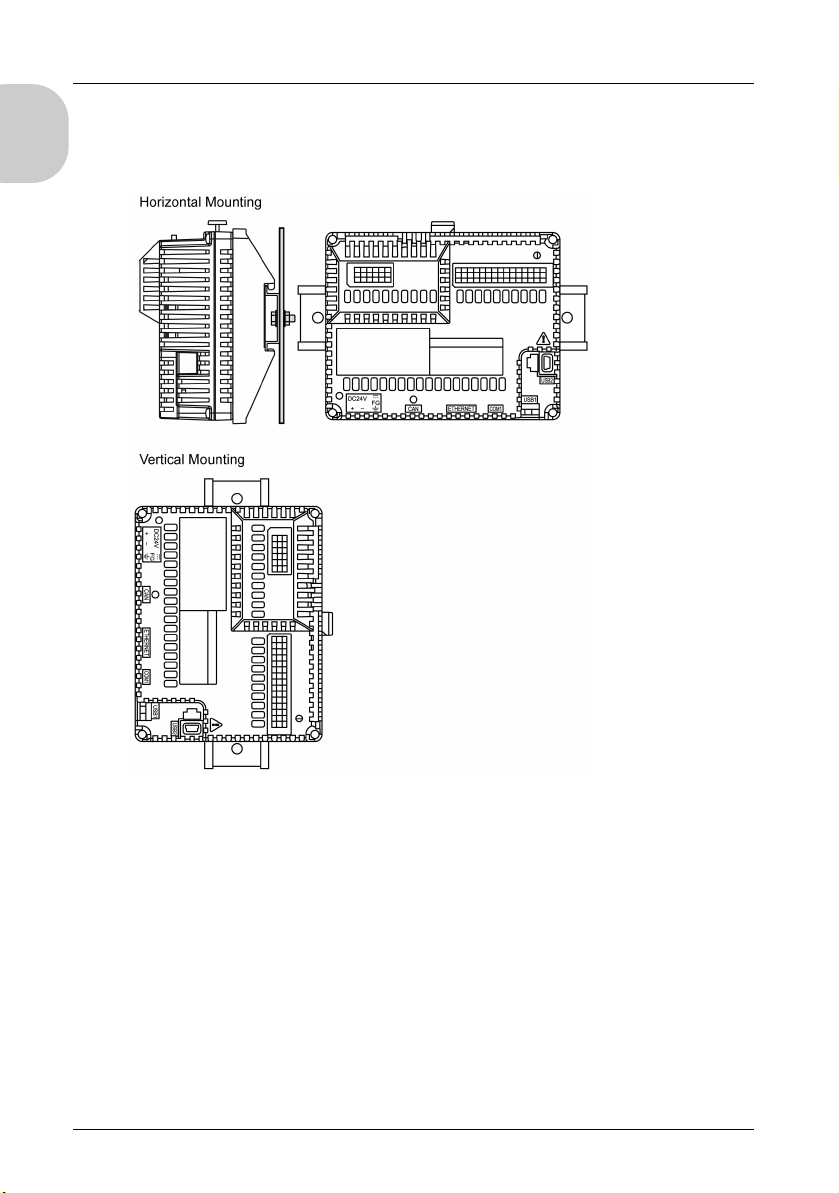
Correct Mounting Position
English
The rear module must be mounted with steel sheet horizontally or vertically plane as
shown in the figure:
NOTE: Keep adequate spacing for proper ventilation to maintain an ambient temperature
between 0...50 ° C (32...122 ° F) for horizontal installation and 0...40 ° C (32...104 ° F) for
vertical installation.
22
Page 23
LT-4201TM/4301TM Installation Guide
Incorrect Mounting Position
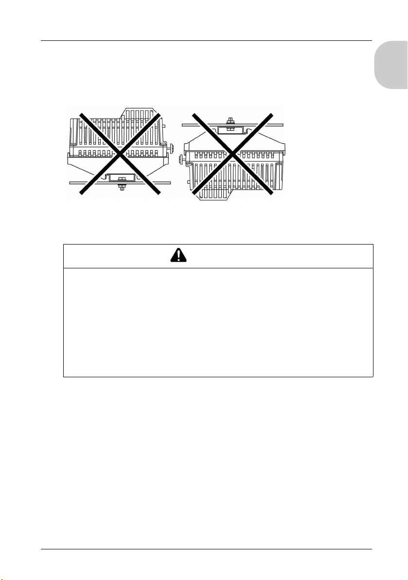
The rear module should only be positioned in correct mounting position to help ensure an
adequate air flow through the product.
The figures show the incorrect mounting positions:
Minimum Clearance When Installing the Rear Module on a DIN Rail
WARNING
UNINTENDED EQUIPMENT OPERATION
Place devices dissipating the most heat at the top of the cabinet and ensure adequate
ventilation.
Avoid placing this equipment next to or above devices that might cause overheating.
Install the equipment in a location providing the minimum clearances from all adjacent
structures and equipment as directed in this document.
Install all equipment in accordance with the specifications in the related
documentation.
Failure to follow these instructions can result in death, serious injury, or equipment
damage.
English
The rear module has been designed as an IP20 product and must be installed in an
enclosure. The clearances must be respected when installing the product:
Distance and separation between the rear module and the front installation panel.
Distance and separation between the rear module and wiring ducts.
Distance and separation between the rear module and peripherals.
23
Page 24
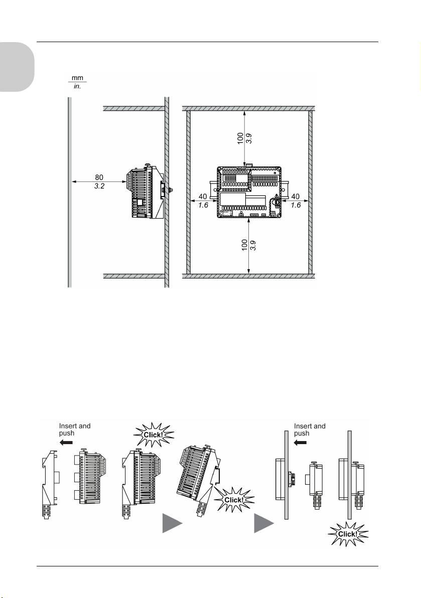
The figure shows the minimum clearance for the rear module:
English
Installing the Rear Module on a DIN Rail
The following procedure describes how to install the rear module on a DIN rail:
Fasten the DIN rail to a panel surface using screws.
Affix the display module/rear module separation cable to the rear module.
Position the top groove of the rear module on the top edge of the DIN rail and press the
assembly against the DIN rail until you hear the DIN rail clip click into place.
Install the display module onto the cabinet.
Affix the display module/rear module separation cable to the display.
The figure shows how to install the rear module on a DIN rail:
24
Page 25
LT-4201TM/4301TM Installation Guide
Removing the Rear Module from a DIN Rail
The following procedure describes how to remove the rear module from a DIN rail:
Push down the yellow lock button of the rear module and remove it from the display
module/rear module separation cable.
Push down the display module/rear module separation cable from the DIN rail.
The figure shows how to remove the rear module from a DIN rail:
English
25
Page 26

English
26
Page 27
LT-4201TM/4301TM Ins tallation Guide
LT-4201TM/4301TM Installation Guide
Wiring Principles
Wiring Principles
Wiring Rules and Recommendations
There are several rules that must be followed when wiring the LT system.
Wiring Guidelines
DANGER
HAZARD OF ELECTRIC SHOCK, EXPLOSION OR ARC FLASH
Disconnect all power from all equipment including connected devices prior to removing
any covers or doors, or installing or removing any accessories, hardware, cables, or
wires except under the specific conditions specified in the appropriate hardware guide
for this equipment.
Always use a properly rated voltage sensing device to confirm the power is off where
and when indicated.
Replace and secure all covers, accessories, hardware, cables, and wires and confirm
that a proper ground connection exists before applying power to the unit.
Use only the specified voltage when operating this equipment and any associated
products.
Failure to follow these instructions will result in death or serious injury.
English
The following rules must be applied when wiring a LT system:
I/O and communication wiring must be kept separate from the power wiring. Route these
2 types of wiring in separate cable ducting.
Verify that the operating conditions and environment are within specification.
Use proper wire sizes to meet voltage and current requirements.
Use copper conductors.
Use twisted-pair, shielded cables for analog, and/or fast I/O.
Use twisted-pair, shielded cables for networks, and fieldbus.
For the power connector, refer to DC power supply wiring diagram.
When terminals A2 and B2 (signal name: Q1, Q0) are wired to external I/O, use the
same power source for external I/O and the LT. Refer to Power Supply Connections.
If you use a temperature sensor with thermocouple inputs, make sure you use the
compensation cable.
Prevent temperature changes to the thermocouple connection terminal. Correct
temperature measurement may not be possible if the thermocouple cold junction (LT’s
thermocouple compensation wiring to the connection terminal) experiences
temperature changes.
27
Page 28
English
Terminal Block
WARNING
IMPROPER GROUNDING CAN CAUSE UNINTENDED EQUIPMENT OPERATION
Use cables with insulated shielded jackets for analog I/O, fast I/O and communication
signals.
Ground shielded cables for analog I/O, fast I/O and communication signals at a single
Always comply with local wiring requirements regarding grounding of cable shields.
Failure to follow these instructions can result in death, serious injury, or
equipment damage.
1
Multipoint grounding is permissible if connections are made to an equipotential ground
plane dimensioned to help avoid shielded cable damage in the event of power system
short circuit currents.
For more details, refer to Grounding Shielded Cables.
The wire sizes to use with the removable terminal blocks is 0.20 to 0.81 mm
18).
point
1
.
2
(AWG 24 to
DANGER
FIRE HAZARD
Use only the recommended wire sizes for I/O channels and power supplies.
Failure to follow these instructions will result in death or serious injury.
Not plugging the terminal block into rear module correctly can cause an electric shock or
unintended operation of the application and/or can damage the rear module.
DANGER
UNINTENDED EQUIPMENT OPERATION OR ELECTRIC SHOCK
Be sure to connect the terminal blocks to their designated location.
Failure to follow these instructions will result in death or serious injury.
NOTE: When installing the terminal blocks to the rear module, please keep the display
module unmounted.
NOTE: To help prevent a terminal block from being inserted incorrectly, clearly and
uniquely code and label each terminal block and rear module.
28
Page 29
LT-4201TM/4301TM Installation Guide
Avoid temperature changes on the thermocouple’s connection terminal. Temperature
measurements may not be accurate due to temperature changes in the cold junction (LT
connection terminal for the thermocouple compensation cable).
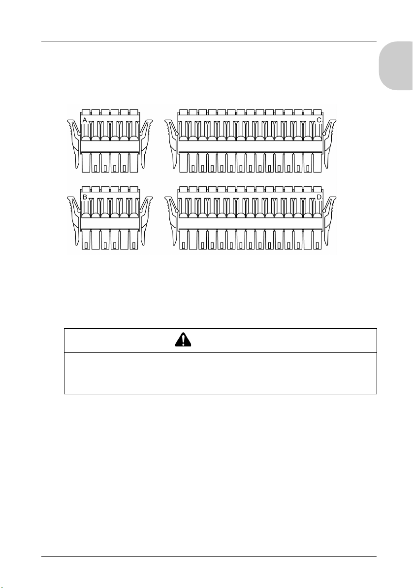
The figure shows the labels on each terminal block:
NOTE: Appearance of the connectors are the same but are different. Check the label and
pin position of each connector before connecting.
Wiring to the DIO Terminal Block
English
CAUTION
EQUIPMENT DAMAGE
Be sure to remove the terminal blocks from the equipment prior to wiring.
Failure to follow these instructions can result in injury or equipment damage.
Screwdriver Required to Wire Terminal Blocks
Recommended type: 1891348-1 (Tyco electronics AMP)
If another manufacturer, be sure that the part has the following dimensions:
point depth: 1.5 mm (0.06 in)
point height: 2.4 mm (0.09 in)
Point shape must be DIN5264A and meet standard DN EN60900.
29
Page 30
English
Procedure
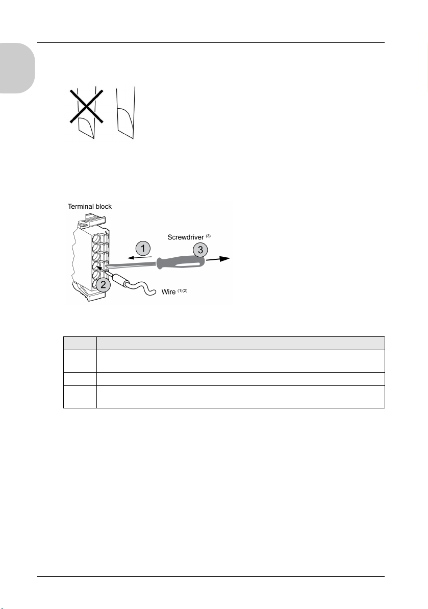
Also, the screwdriver tip must be flat, as indicated, to access the narrow hole of the
terminal block:
The terminal blocks are a spring clamp type.
Use the following procedure to connect the wires to the terminal blocks:
Step Action
1 Insert the screwdriver into the square-shaped hole.
This will open the wire’s round-shaped hole.
2 Hold the screwdriver and insert the wire into the wire’s round-shaped hole.
3 Take out the screwdriver from the square-shaped hole.
The round-shaped hole will then close, and the wire will be held securely in place.
NOTE: To remove the wire, reinsert the screwdriver into the square-shaped hole and when
the wire’s spring clamp releases, pull out the wire.
(1)
Wire should be 0.20...0.81 mm2 (AWG 24...18), with the end twisted. Applicable wire
style are UL1015 and UL1007.
(2)
Strip 7.0 mm (0.28 in) of jacket from the wire. Strip only the amount of jacket required.
If too much jacket is removed, the ends may short against each other or against the
terminals, which can create an electric short. If not enough jacket is removed, the wire may
not make sufficient contact with the terminal.
Insert each wire completely into its opening. Improper insertion can lead to a loss of unit
power or short circuit, either against the wire filaments or against the terminals, or to over
heating of the wire and terminal.
30
Page 31
LT-4201TM/4301TM Installation Guide
(3)
Do not rotate the point of the screwdriver inside the square-shaped opening. It may
damage the equipment.
WARNING
IMPROPER WIRING PRACTICES CAN MAKE EQUIPMENT INOPERABLE
Use only the specified wire sizes for I/O channels and power supplies.
Prepare wires and make connections as specified in this documentation.
Do not connect more than one wire per terminal block connector.
Failure to follow these instructions can result in death, serious injury, or equipment
damage.
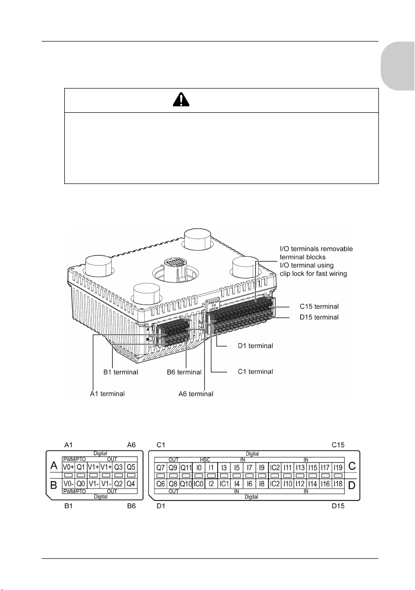
Terminal Blocks
The figure shows the terminal blocks:
English
The figure shows the pin assignment of the LT-4201TM (Modular Type DIO), LT-4301TM
(Modular Type DIO) and LT-4000M (Modular Type DIO) terminal blocks:
NOTE: Confirm the connector label ABCD and the stamp ABCD on the unit before wiring.
31
Page 32
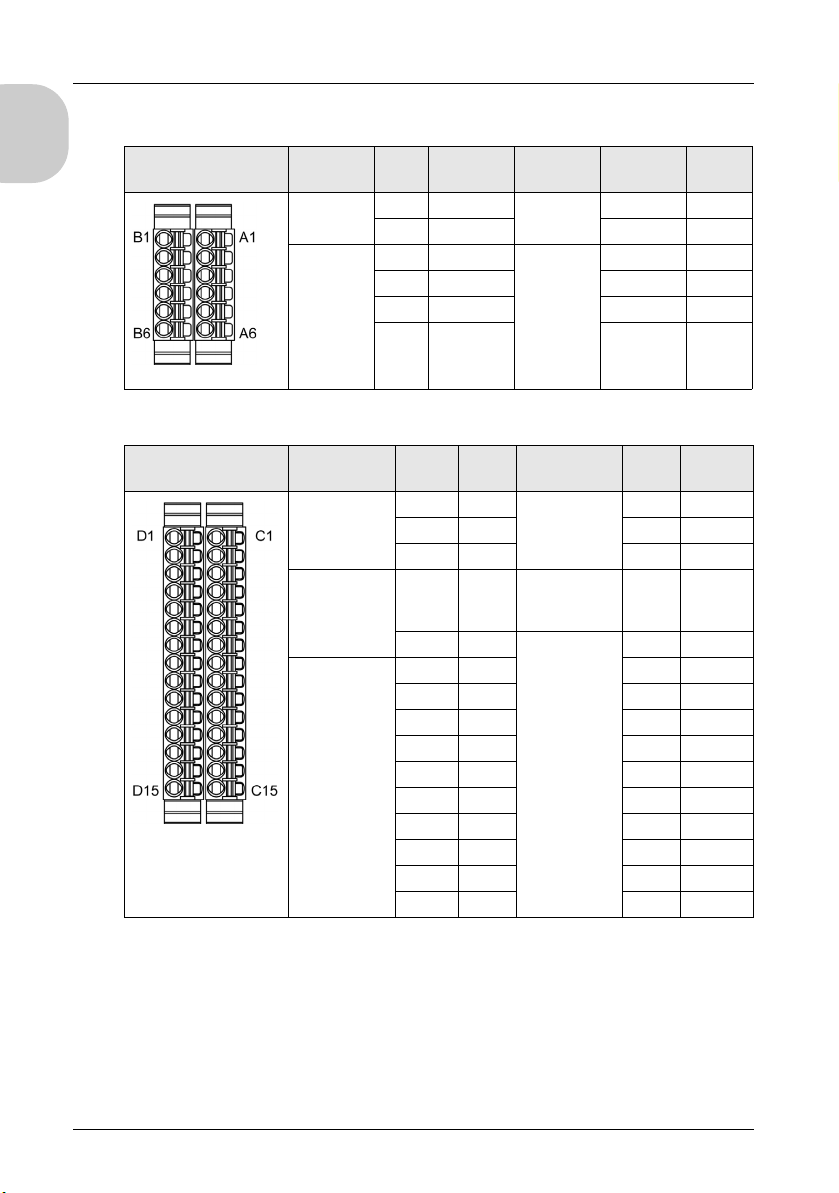
The figure shows the groups and the signal names of the terminal blocks:
English
Pin Arrangement Group Pin Signal
Fast Output A1 V0+ Fast Output B1 V0-
Standard
Output
Name
A2 Q1 B2 Q0
A3 V1+ Standard
A4 V1+ B4 V1-
A5 Q3 B5 Q2
A6 Q5 B6 Q4
Group Pin Signal
B3 V1-
Output
The figure shows the groups and the signal names of the terminal blocks:
Pin Arrangement Group Pin Signal
Standard
Output
Fast
Input/Standard
Input
Standard Input C6 I3 D6 IC1
C1 Q7 Standard
C2 Q9 D2 Q8
C3 Q11 D3 Q10
C4 I0 Fast
C5 I1 Standard Input D5 I2
C7 I5 D7 I4
C8 I7 D8 I6
C9 I9 D9 I8
C10 IC2 D10 IC2
C11 I11 D11 I10
C12 I13 D12 I12
C13 I15 D13 I14
C14 I17 D14 I16
C15 I19 D15 I18
Group Pin Signal
Name
Output
Input/Standard
Input
Name
Name
D1 Q6
D4 IC0
32
Page 33
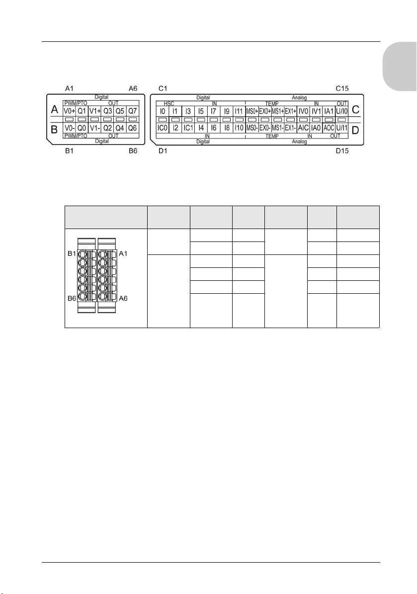
LT-4201TM/4301TM Installation Guide
The figure shows the pin assignment of the LT-4201TM (Modular Type Analog), LT4301TM (Modular Type Analog) and LT-4000M (Modular Type Analog) terminal blocks:
NOTE: Confirm the connector label ABCD and the stamp ABCD on the unit before wiring.
The figure shows the group and the signal names of the terminal blocks:
English
Pin Arrangement Group Pin Signal
Name
Fast Output A1 V0+ Fast Output B1 V0-
A2 Q1 B2 Q0
Standard
Output
A3 V1+ Standard
A4 Q3 B4 Q2
A5 Q5 B5 Q4
A6 Q7 B6 Q6
Group Pin Signal
Name
B3 V1-
Output
33
Page 34
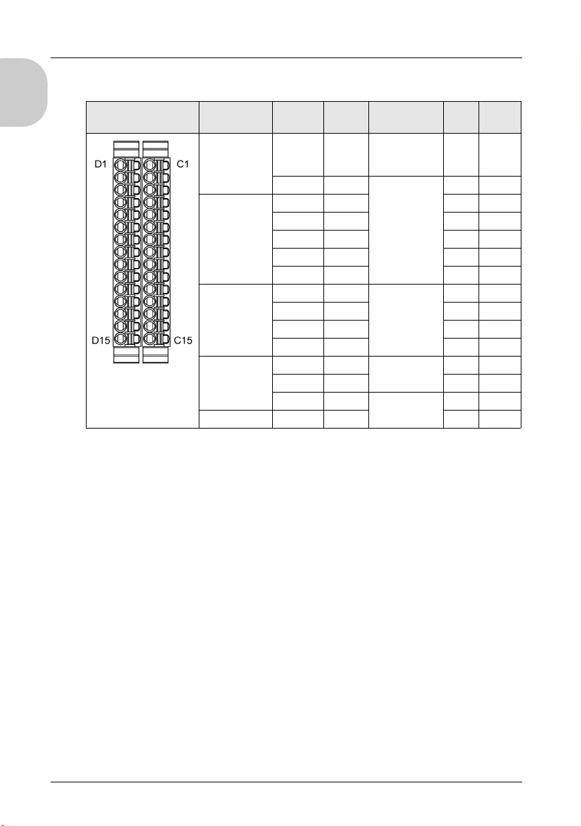
The figure shows the group and the signal names of the terminal blocks:
English
Pin Arrangement Group Pin Signal
Connecting the Power Cord
Follow these instructions when supplying power to the unit:
When the frame ground (FG) terminal is connected, verify the wire is grounded. Not
grounding the unit can result in excessive Electromagnetic Interference (EMI).
Grounding is required to meet EMC level immunity.
The shield ground (SG) and FG terminals are connected internally in the unit.
Remove power before wiring to the power terminals of the unit.
The unit uses 24 Vdc power. Using any other level of power can damage both the
power supply and the unit.
Since the unit is not equipped with a power switch, connect a power switch to the unit’s
power supply.
Field wiring terminal marking for wire type (75° C (167F) copper conductors only).
Name
Fast
Input/Standard
Input
Standard Input C3 I3 D3 IC1
Temperature
Input
Analog Input C12 IV0 Analog Input D12 AIC
Analog Output C15 U/I0 D15 U/I1
C1 I0 Fast
C2 I1 Standard Input D2 I2
C4 I5 D4 I4
C5 I7 D5 I6
C6 I9 D6 I8
C7 I11 D7 I10
C8 MS0+ Temperature
C9 EX0+ D9 EX0-
C10 MS1+ D10 MS1-
C11 EX1+ D11 EX1-
C13 IV1 D13 IA0
C14 IA1 Analog Output D14 AOC
Group Pin Signal
Name
D1 IC0
Input/Standard
Input
D8 MS0Input
34
Page 35
LT-4201TM/4301TM Installation Guide
Power Cord Preparation
Before using your power cord:
Verify that the ground wire is the same gauge or heavier than the power wires.
Do not use aluminum wires for the power supply’s power cord.
If the conductor end (individual) wires are not twisted correctly, the end wires may either
short loop to each other or against an electrode. To avoid this, use D25CE/AZ5CE cable
ends.
Use wires that are 0.75 to 2.5 mm
2
(18 to 12 AWG) for the power cord, and twist the wire
ends before attaching the terminals.
The conductor type is solid or stranded wire.
To reduce electromagnetic noise, make the power cord as short as possible.
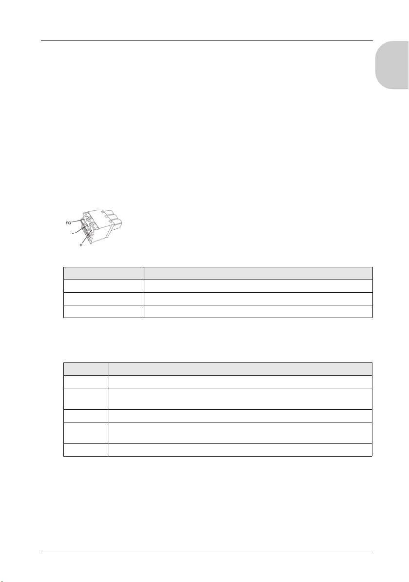
Power Plug Illustration
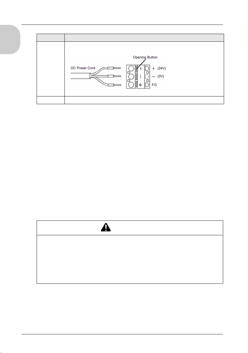
Connection Wire
+24Vdc
-0Vdc
FG Grounded terminal connected to the unit chassis
English
Connecting the Power Cord
The table explains how to connect the power plug:
Step Action
1 Confirm the power cord is not connected to the power supply.
2 Check the rated voltage and remove the "DC24V" sticker on the DC power supply
connector.
3 Remove 10 mm (0.39 in.) of the vinyl membrane off the ends of the power code wires.
4 If using stranded wire, twist the ends. Tinning the ends with solder reduces risk of
fraying and ensures good electrical transfer.
5 Push the Opening button with a small and flat screwdriver to open the desired pin hole.
35
Page 36
English
Step Action
6 Insert each pin terminal into its corresponding hole. Release the Opening button to
clamp the pin in place.
7 After inserting all three pins, insert the power plug into the power connector on the LT.
NOTE:
Do not solder the wire directly to the power receptacle pin.
The power supply cord must meet the specification shown above. Twist the power
cords together, up to the power plug, for EMC compliance.
Use field wiring terminal marking for wire type (75 ° C (167 ° F) copper conductors only).
Precautions:
Connect the power cord to the power connector on the rear module using the power
plug.
Use a regulated power supply with a Class 2 power supply between the line and the
ground.
Do not bundle the power supply cord with, or keep close to, main circuit lines (high
voltage, high current), or I/O signal lines.
Connect a lightning surge absorber to handle power surges.
Excessive stress on the power connection or attempting to install the rear module with the
power cables connected may disconnect, or cause damage, to the power connections.
This can cause short circuits, fire, or unintended equipment operation.
WARNING
SHORT CIRCUITS, FIRE, OR UNINTENDED EQUIPMENT OPERATION
Securely attach power cables to the panel or cabinet.
Secure the power plug of the rear module.
Install and fasten the rear module on the installation panel or cabinet prior to
connecting power supply and communication lines.
Failure to follow these instructions can result in death, serious injury, or
equipment damage.
36
Page 37
LT-4201TM/4301TM Installation Guide
Power Supply Connections
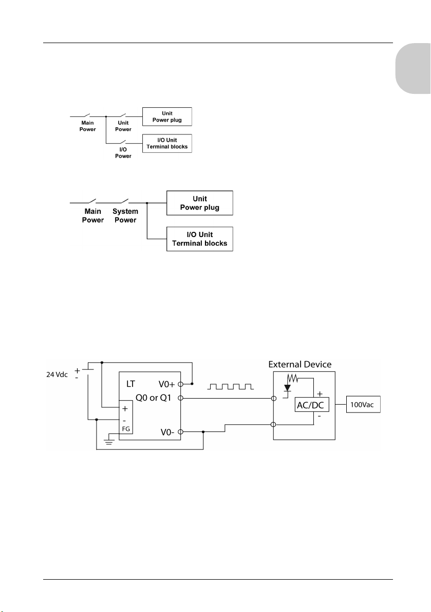
For maintenance purpose, use the following connection diagram to set up your power
supply connections. However, when terminals A2 and B2 (signal name: Q1, Q0) are wired
to external I/O, use the same power source for external I/O and the LT:
When wiring terminals A2 and B2 (signal name: Q1, Q0) to external I/O:
NOTE:
When connector A2 and B2 (Signal Name: Q1, Q0) are wired to external I/O, turn on the
LT before turning on the external device. Otherwise the wrong signal for Pulse Output,
PWM Output and High-speed Counter (Synchronize Output) will be output. When
transferring a program that turns off or resets the LT, first turn off the external device.
When using a system with multiple power supplies, please note there is also a power
supply in the external device.
English
Ground the surge absorber separately from the rear module.
Select a surge absorber that has a maximum circuit voltage greater than the peak
voltage of the power supply.
37
Page 38
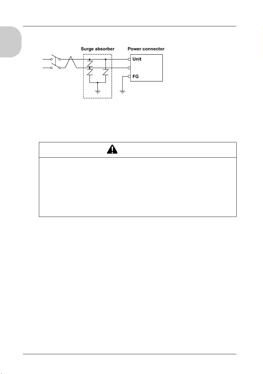
The diagram illustrates a lightning surge absorber connection:
English
Grounding the System
To minimize the effects of electromagnetic interference, cables carrying the fast I/O,
analog I/O, and Serial communication signals must be shielded.
IMPROPER GROUNDING CAN CAUSE UNINTENDED EQUIPMENT OPERATION
Use cables with insulated shielded jackets for analog I/O, fast I/O and communication
Ground shielded cables for analog I/O, fast I/O and communication signals at a single
Always comply with local wiring requirements regarding grounding of cable shields.
Failure to follow these instructions can result in death, serious injury, or
equipment damage.
signals.
point
WARNING
1
.
1
To avoid damage to the shielded cable when there is a short circuit in the power line, set
up a multi-point frame ground (FG) each with the same electric potential.
The use of shielded cables requires compliance with the following wiring rules:
When there is no protective earth ground, you can use metal conduit or cable duct
shield as a part of the protective earth ground. The functional ground (FE) shield must
attenuate electromagnetic interference and must be shielded the length of the cable. If
the purpose is for both functional and protective grounding, as is often the case for
communication cables, the cable must have continuous shielding.
Wherever possible, keep cables carrying one type of signal separate from the cables
carrying other types of signals or power.
Protective Earth Ground on the Backplane
For protective grounding, connect braided copper cable (that can withstand the maximum
voltage/current allowed by the system) to the conductive backplane.
38
Page 39
LT-4201TM/4301TM Installation Guide
Functional Ground on the DIN Rail
The DIN rail for your LT system is common with the functional ground plane and must be
mounted on a conductive backplane.
WARNING
UNINTENDED EQUIPMENT OPERATION
When connecting DIN rails, connect the DIN rails to functional ground (FE).
Failure to follow these instructions can result in death, serious injury, or equipment
damage.
Shielded Cable Connections
Cables carrying the fast I/O, analog I/O, and Serial communication signals must be
shielded. The shielding must be securely connected to ground. The fast I/O and analog I/O
shields may be connected either to the functional ground (FE) or to the protective earth
ground (PE) of your LT.
WARNING
ACCIDENTAL DISCONNECTION FROM PROTECTIVE GROUND (PE)
Do not use the grounding bar to provide a protective earth ground (PE).
Use the grounding bar only to provide a functional ground (FE).
Failure to follow these instructions can result in death, serious injury, or equipment
damage.
English
DANGER
HAZARD OF ELECTRIC SHOCK
Make sure that CANopen and Modbus cables are securely connected to the protective
earth ground (PE).
Failure to follow these instructions will result in death or serious injury.
NOTE: The functional ground of the Ethernet connection is internal.
39
Page 40
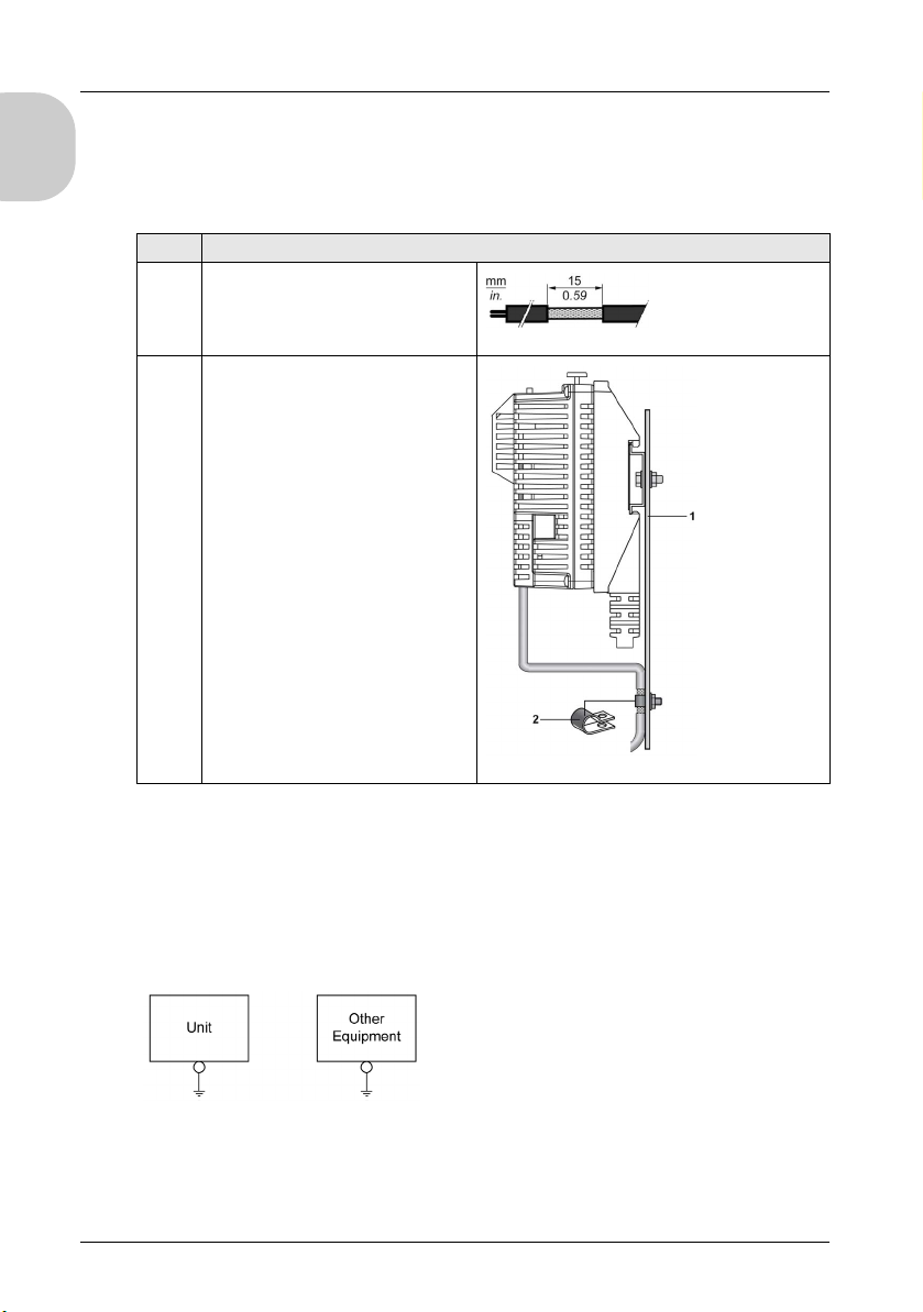
Protective Earth Ground (PE) Cable Shielding
The following shows the steps when using shield cables for grounding the LT power
English
supply, Standard I/O, High-speed I/O, Analog I/O, Temperature Input, Communication
cable so on.
Step Description
1 Strip the shielding for a length of
15 mm (0.59 in.).
2 Use the metal grounding clamp(2) to
attach the cable to the backplane plate
(1) as close as possible to the LT.
NOTE: The shielding must be clamped securely to the conductive backplane to ensure
good contact.
Exclusive Grounding
Connect the frame ground (FG) terminal on the power plug to an exclusive ground. When
supplying power to the LT unit, be sure to separate the input, output and power lines, as
shown:
40
Page 41
LT-4201TM/4301TM Installation Guide
Common Grounding
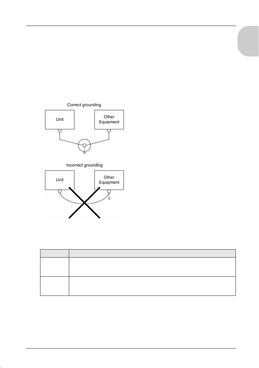
If exclusive grounding is not possible, use a common grounding point. Use grounding
resistance of 10 Ω or less, wire thickness of 2.6 mm or more, or your country’s applicable
standard for the grounding point.
Precautions:
Do not use common grounding, since it can lead to accidents and machine breakdown.
If the equipment does not function properly when grounded, disconnect the ground wire
from the FG terminal.
If exclusive grounding is not possible, use a common connection point.
English
Grounding Procedure
Step Action
1 Check that the grounding resistance is less than 100 Ω.
(Grounding resistance of 100 Ω or less, wire thickness of 1.6 mm or more, or your
country’s applicable standard.)
2 Create the connection point as close to the unit as possible, and make the wire as short
as possible. When using a long grounding wire, replace the thin wire with a thicker wire,
and place it in a duct.
NOTE: FG and SG terminals are internally connected in the LT. When connecting an
external device to the LT using the SG terminal, be sure to check that no short-circuit loop
is created when you setup the system.
41
Page 42

English
42
Page 43
LT-4201TM/4301TM Ins tallation Guide
Communication Interfaces
LT-4201TM/4301TM Installation Guide
Communication Interfaces
Communication Interfaces
USB Device
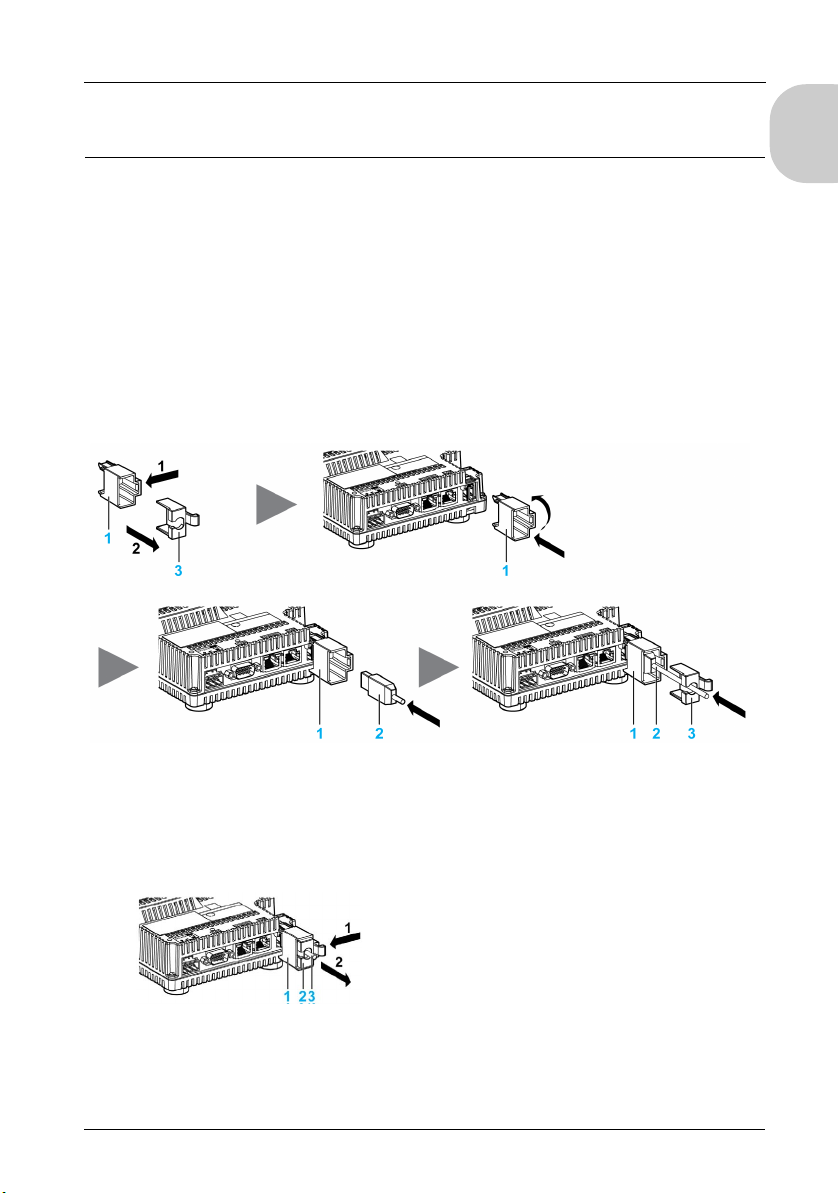
When using a USB device, you can attach a USB holder to the USB interface on the side
of the unit to prevent the USB cable from being disconnected.
Attaching the USB Type A Holder
Hook the upper pick of the USB holder to the attachment hole and insert the lower pick to
fix the USB holder in place.
English
1 USB holder
2 USB cable
3 USB cover
Removing the USB Type A Holder
Push down the tab of the USB holder and then remove the USB cover.
1 USB holder
2 USB cover
3 USB cable
43
Page 44
Communication Interfaces
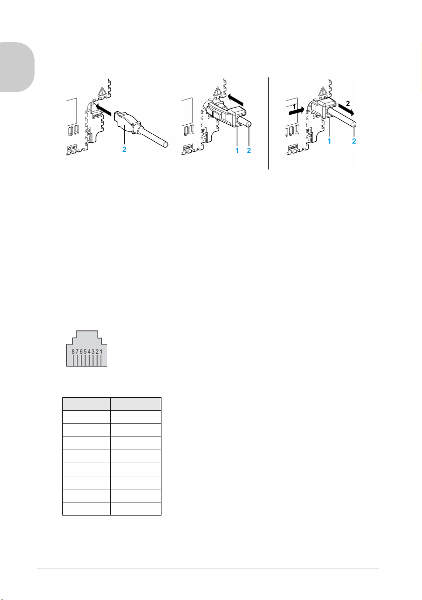
Attaching and Removing the USB Mini-B Holder
English
1 USB holder
2 USB cable
NOTE: The USB holder is supplied in the accessory kit PFXZGMAK1 (sold separately).
Ethernet Interface
Do not confuse the RJ45 Ethernet connector with the RJ45 interface.
NOTE: Ethernet networks should be installed by a trained and qualified person.
When you use a 1:1 connection to connect to a device such as PC, you can use a cross
cable, but we recommend using a hub.
Ethernet Interface Pin Assignment
The figure shows the RJ45 Ethernet connector pin assignment:
The table describes the RJ45 Ethernet connector pins:
Pin Signal
1TD+
2TD-
3 RD+
4–
5–
6 RD-
7–
8–
NOTE: The LT supports the MDI/MDIX auto-crossover cable function. You do not have to
use special Ethernet crossover cables to connect devices directly to this interface
(connections without an Ethernet hub or switch).
44
Page 45
LT-4201TM/4301TM Installation Guide
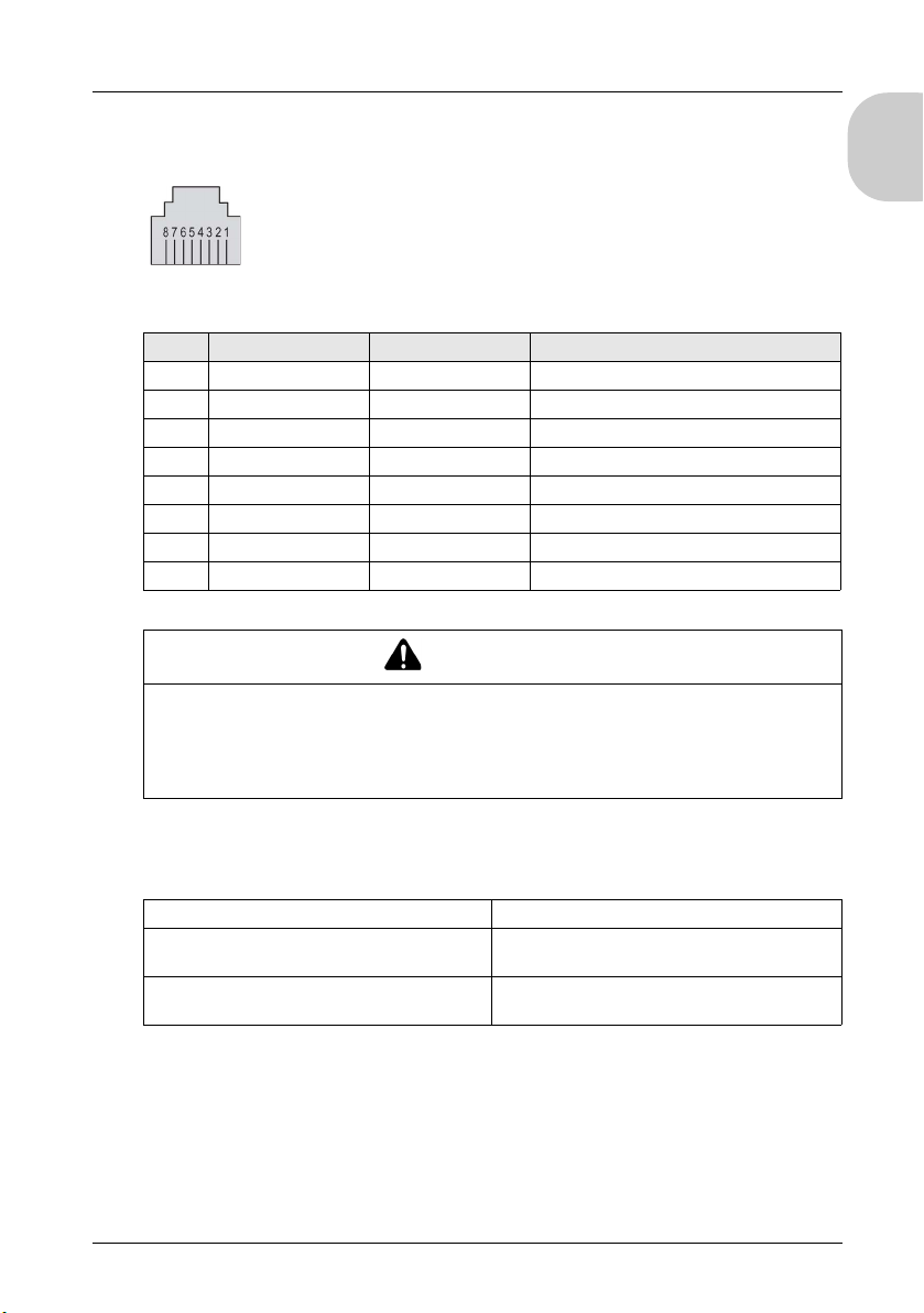
Serial Interface Pin Assignment COM1
The figure shows the pins of the RJ45 connector when viewed from LT:
The table describes the pin assignment of the RJ45 connector:
Pin RS-232C RS-485 Description
1 RxD N.C. Received data (RS-232C)
2 TxD N.C. Transmitted data (RS-232C)
3 N.C. N.C. Not connected
4 N.C. D1+ Differential data (RS-485)
5 N.C. D0- Differential data (RS-485)
6 N.C. N.C. Not connected
7 N.C. N.C. Not connected
8 GND GND Signal ground
WARNING
UNINTENDED EQUIPMENT OPERATION
Do not connect wires to unused terminals or terminals marked “Not Connected (N.C.)”.
Failure to follow these instructions can result in death, serious injury, or equipment
damage.
English
CANopen Capabilities
The LT CANopen master has the following features:
Maximum number of slaves on the bus 16 CANopen slave devices
Maximum length of CANopen fieldbus cables According to the CAN specification (see cable
Maximum number of PDOs managed by the
master
length and transmission speed).
32 TPDOs + 32 RPDOs
For each additional CANopen slave:
The application size increases by an average of 10 KB that can result in a memory size
overload.
The configuration initialization time at startup increases, which can lead to a watchdog
condition.
45
Page 46
Communication Interfaces
Although LT does not restrict you from doing so, we recommend that you not exceed
16 CANopen slave modules (and/or 32 TPDOs and 32 RPDOs) for sufficient performance
English
tolerance and to avoid performance degradation.
UNINTENDED EQUIPMENT OPERATION
Do not connect more than 16 CANopen slave devices to the LT.
Failure to follow these instructions can result in death, serious injury, or
equipment damage.
DEGRADATION OF PERFORMANCE
Do not exceed 32 TPDOs and 32 RPDOs for the LT.
Failure to follow these instructions can result in equipment damage.
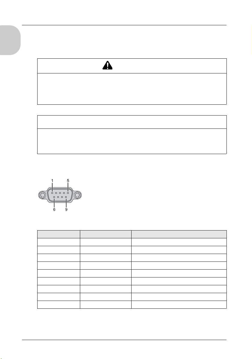
CANopen Interface Pin Assignment
The graphic describes the pins of the CANopen interface:
WARNING
NOTICE
The table describes the pins of the CANopen interface:
Pin Signal Description
1 N.C. Reserved
2 CAN_L CAN_L bus line (Low)
3 CAN_GND CAN 0 Vdc
4 N.C. Reserved
5CAN_SHLDN.C.
6GND 0Vdc
7 CAN_H CAN_H bus line (High)
8 N.C. Reserved
9 N.C. Reserved
The shield is connected to pin 6, the 0 Vdc pin.
NOTE: Pin 9 is not connected internally. The controller does not provide power on
CAN_V+.
46
Page 47
LT-4201TM/4301TM Installation Guide
WARNING
UNINTENDED EQUIPMENT OPERATION
Do not connect wires to unused terminals or terminals marked “Not Connected (N.C.)”.
Failure to follow these instructions can result in death, serious injury, or equipment
damage.
System LED Display
NOTE:
Ethernet LEDs are mounted next to the I/O terminal block.
CANopen LED is mounted alongside the cover.
System LED Description
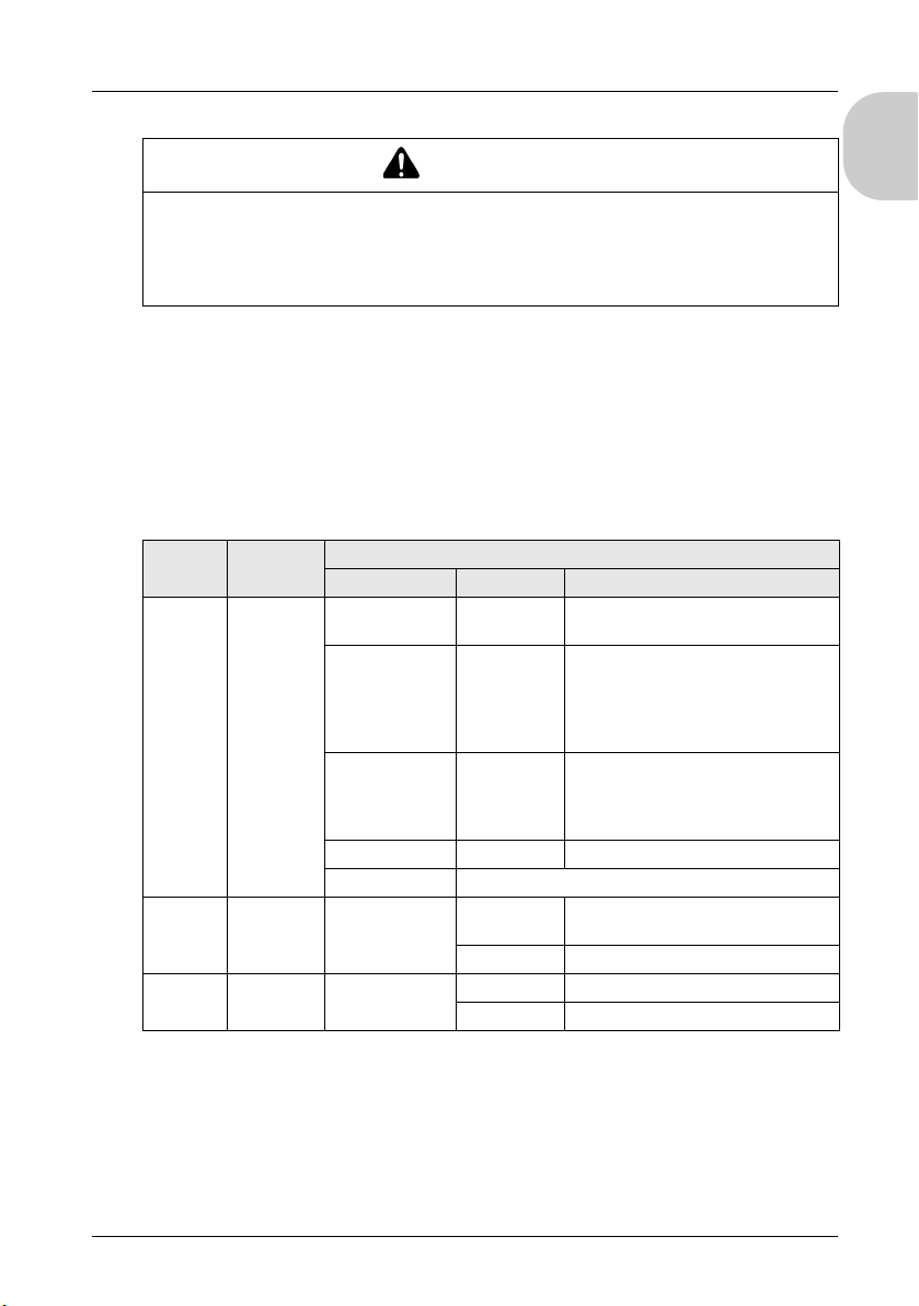
The table describes the status LEDs operations:
Label Description LED
Color Status Description
CAN STS CANopen
status
IND1 Ethernet
status
IND2 Ethernet
activity
OFF No CANopen
Single flash red /
with green ON
Double flash red /
with green ON
Red ON Bus off The CANopen bus is stopped.
Green ON The CANopen bus is operational.
Green Off No connection or subsequent
Green Off No data transmission.
configured
Acceptable
detected error
limit threshold
has been
reached
Node
Guarding or
Heartbeat
event
On Data transmission is available.
On Data transmission is occurring.
CANopen is not active in the
application.
The controller has detected that the
maximum number of error frames has
been reached or exceeded.
The controller has detected either a
Node Guarding or Heartbeat exception
for the CANopen master or slave
device.
transmission failure.
English
47
 Loading...