


 Loading...
Preface
Thank you for purchasing Pro-face’s LT3000 Series Graphic Logic Controller Interface (Hereafter referred to as the “LT unit”).
Before operating your LT unit, be sure to read this manual to familiarize yourself with the LT unit’s operation procedures and features.
NOTICE
1.Copying this manual’s contents, either in whole or in part, is prohibited without the express permission of Digital Electronics Corporation, Japan.
2.The information contained in this manual is subject to change without notice.
3.If you should you find any errors or omissions in this document, please contact Digital Electronics Corporation to report your findings.
4.Please be aware that Digital Electronics Corporation shall not be held liable by the user for any damages, losses, or third party claims arising from the uses of this product.
Copyright ©2012.11 Digital Electronics Corporation. All Rights Reserved.
Product names used in this manual are the trademarks / registered trademarks of their respective owners.
1
Essential Safety Precautions
All safety-related procedures stated in this document must be followed to operate the LT correctly and safely. Be sure to read this and any related documents thoroughly to understand the correct operation and functions of the LT unit.
Safety Icons
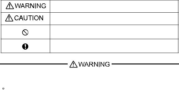
Throughout this manual, these icons provide essential safety information for LT operation procedures requiring special attention. These icons indicate the following levels of danger:
Indicates situations where severe bodily injury, death or major equipment damage can occur.
Indicates situations where slight bodily injury or minor equipment damage can occur.
Indicates actions or procedures that should NOT be performed.
Indicates actions or procedures that MUST be performed to ensure correct unit operation.
System Design
 Be sure to design your LT control system so that, in the event of a main power supply failure or a LT accident, the user system’s overall safety integrity will be maintained. If this is not done, incorrect output signals or a LT malfunction may cause an accident.
1)Interlock and other circuits designed to interrupt or oppose normal machine movement (such as Emergency Stop, General Protection, and forward and reverse rotation), as well as those designed to prevent machine damage (such as upper, lower, and traverse movement limit positioning) should all be designed to be located outside of the LT.
2)When the LT generates a “Watchdog Timer Error,” during logic program operating, the logic program operation will halt. Also, when Errors occur in Input/Output control areas that the LT cannot detect, unexpected movement may occur in those areas. Therefore, and to prevent unsafe machine movement, a “Failsafe Circuit” should be created which is completely external to the LT.
For a failsafe circuit, refer to “4.2.5 Installation Precautions” (page 4-13).
3)If a problem arises with an external unit’s relay or transistor, causing an output (coil) to remain either ON or OFF, a major accident can occur. To prevent this, be sure to set up external watchdog circuits that will monitor vital output signals.
2

 Design a circuit that will supply power to the LT unit’s I/O before starting up the LT. If the LT unit’s internal program enters RUN mode prior to the I/O unit’s load control power turning ON, an incorrect output (signal) or malfunction could cause an accident.
 Design a user program that ensures the safety of the user’s system, in the event of a LT display or control error, or either a data transmission error or power failure between the LT and a connected unit. These types of problems can lead to an incorrect output (signal) or malfunction, resulting in an accident.
 Do not make switches using the switches on the touch panels which may cause operator injury and machine damage. An output may remain either ON or OFF and a major accident can occur. To prevent this, set up circuits such as limiters that will monitor vital output signals. Design switches for important operations to be performed by separate devices. An incorrect output or malfunction can occur and thereby cause an accident.
 Do not create LT touch panel switches to control machine safety operations, such as an emergency stop switch. Install these switches as separate hardware switches, otherwise severe bodily injury or equipment damage can occur.
 When using the LT with transportation vehicles (trains, cars, and ships), disaster and crime prevention devices, various types of safety equipment, and medical devices that are not life-support related, use redundant and/or failsafe system designs to ensure proper reliability and safety.
 Do not use the LT as a warning device for critical alarms that can cause serious operator injury, machine damage or can halt system operation. Critical alarm indicators and their control/activator units must be designed using stand-alone hardware and/or mechanical interlocks.
 Do not use the LT with aircraft control devices, aerospace equipment, central trunk data transmission (communication) devices, nuclear power control devices, or medical life support equipment, due to these devices’ inherent requirements of extremely high levels of safety and reliability.
 When using the LT with transportation vehicles (trains, cars, and ships), disaster and crime prevention devices, various types of safety equipment, and medical devices that are not life-support related, use redundant and/or failsafe system designs to ensure proper reliability and safety.
 After the LT unit’s backlight burns out the touch panel is still active, unlike the LT unit’s “Standby Mode”. If the operator fails to notice that the backlight is burned out and touches the panel, a potentially dangerous machine operation error can occur. Therefore, do not create LT unit touch panel switches that may cause injury and/or equipment damage. If your LT unit’s backlight suddenly turns OFF, use the following steps to determine if the backlight is actually burned out.
1)If the LT unit’s “Backlight Control” is not set and the screen has gone blank, your backlight is burned out.
2)If the LT unit’s “Backlight Control” is set to Standby Mode and the screen has gone blank, and touching the screen or performing another input operation does not cause the display to reappear, your backlight is burned out.
3

Handling
 Do not disassemble or modify the LT unit. Doing so may cause a fire or an electric shock.
 Do not operate the LT in an environment where flammable gases are present, since it may cause an explosion.
Wiring
 To prevent electrical shock or equipment damage, unplug the LT unit’s power cord from the power supply prior to installing or wiring the LT.
 To prevent an electric shock be sure to disconnect your LT unit’s power cord from the power supply before wiring the LT.
 Do not use the voltage not specified in the manual. Doing so may cause a fire or an electric shock.
 The cables connected to the LT should be secured by cable clamps to prevent weight or tension of the cables added to the connectors or terminals.
 The LT unit’s wiring should be checked to confirm that both the operating voltage and wiring terminal locations are correct. If either the voltage or the wiring terminal location is incorrect, it can cause a fire or accident.
Maintenance
 NEVER touch a live power terminal. Doing so could cause an electrical shock or a machine malfunction.
 To prevent an electrical shock, unplug the LT unit’s power cord before either cleaning the LT or attaching/ detaching the power terminal attachment screws.
 Do not connect or disconnect Host and LT unit communication cables while the LT is turned ON.
 Do not replace the LT unit’s battery yourself. The LT uses a lithium battery for backing up its internal clock data and the battery may explode if it is replaced incorrectly. When replacement is required, please contact your local LT distributor.
Wiring Layout Precautions
 To prevent a LT unit malfunction due to excessive noise, isolate all LT input/output signal lines from all power wiring or power cables via a separate wiring duct.
Installation
 Be sure all cable connectors are securely attached to the LT unit. A loose connection may cause incorrect input or output signals.
4

Wiring
 Be sure to ground the LT unit’s FG wire separately from other equipment FG lines. Also, be sure to use a grounding resistance of 100Ω or less and a 2mm2 [0.0062inch2] or thicker wire, or your country’s applicable standard. Otherwise, electric shock or malfunctions may result.
 Be sure to use only the designated torque to tighten the LT unit’s terminal block screws. If these screws are not tightened firmly, it may cause a short-circuit, fire or incorrect unit operation.
 Be sure that metal particles and wiring debris do not fall inside the LT unit. They can cause a fire, malfunction or incorrect unit operation.
Maintenance
 Be sure to read the LT unit’s manual carefully before performing program changes, entering forced output, or using the RUN, STOP, or PAUSE commands while the LT is operating. Mistakes made when using these items can cause machine accidents or damage.
 Be sure the electricity is turned OFF before attaching or detaching an I/O unit. If the electricity is ON when an I/O unit is attached or detached, damage or malfunction to the I/O unit may occur.
Unit Disposal
 When the product is disposed of, it should be disposed of in a manner appropriate to, and in accordance with, the user country's industrial machinery disposal/recycling standards.
General Safety Precautions
 Do not press on the LT unit’s display with excessive force or with a hard object, since it can damage the display. Also, do not press on the touch panel with a pointed object, such as the tip of a mechanical pencil or a screwdriver, since doing so can damage the touch panel.
 Do not install the LT where the ambient temperature exceeds the specified range. Doing so may cause a unit malfunction.
 To prevent abnormally high temperatures from occurring inside the LT, do not restrict or block the LT unit’s rear-face ventilation slots.
 Do not operate the LT in areas where large, sudden temperature changes can occur. These changes can cause condensation to form inside the LT, possibly causing it to malfunction.
 Do not allow water, liquids or metal fragments to enter inside the LT unit’s case, since they can cause either a malfunction or an electric shock. The allowable pollution degree is 2.
 Do not operate or store the LT in locations where it can be exposed to direct sunlight, high temperatures, excessive dust, moisture or vibration.
 Do not operate or store the LT where chemicals evaporate, or where chemicals are present in the air. Corrosive chemicals: Acids, alkalines, liquids containing salt
Flammable chemicals: Organic Solvents
5

 Do not use paint thinner or organic solvents to remove dirt or oil from the LT unit’s surface. Instead, use a soft cloth moistened with a diluted neutral detergent.
 Do not use or store the LT in areas with direct sunlight, since the sun’s ultraviolet rays may cause the LCD’s quality to deteriorate.
 Do not store the LT in an area where the temperature is lower than that recommended in the LT unit’s specifications. Doing so may cause the LCD display’s liquid to congeal, which can damage the LCD. Also, if the storage area’s temperature becomes higher than the specified level, the LCD’s liquid may become isotropic, causing irreversible damage to the LCD. Therefore, only store the LT in areas where temperatures are within the LT unit’s specifications.
 After turning OFF the LT, be sure to wait for 5 seconds before turning it ON again. The LT may not operate correctly if it is restarted too quickly.
 Be sure to back up the LT screen data and logic programs in case they are lost accidentally.
LCD Panel Usage Precautions
•The LCD panel’s liquid contains an irritant. If the panel is damaged and any of this liquid contacts your skin, immediately rinse the area with running water for at least 15 minutes. If the liquid gets in your eyes, immediately rinse your eyes with running water for at least 15 minutes and consult a doctor.
•The LT unit’s LCD screen may flicker or show unevenness in the brightness of certain images or at some contrast settings. This is an LCD characteristics and not a product defect.
•There’s an individual difference in brightness and tone of LCD screen. Please be aware of this difference before using the lined-up plural units.
•Depending on the ambient temperature, LCD displays may sometimes look whitish (at high temperatures) or blackish (at low temperatures). This is an LCD characteristic and not a product defect.
•Some of LT unit's LCD screens may contain light or dark pixels. This is an LCD characteristic and not a product defect.
•Extended shadows, or “Crosstalk” may appear on the sides of screen images. This is an LCD characteristic and not a product defect.
•The color displayed on the LT unit’s LCD screen may appear different when seen from outside the specified viewing angle. This is an LCD characteristic and not a product defect.
•When the same image is displayed on the LT unit’s screen for a long period, an afterimage may appear when the image is changed. This is an LCD characteristic and not a product defect.
•To prevent an afterimage:
*Set the LT unit’s display OFF feature when you plan to display the same screen image for a long period of time.
*Change the screen image periodically and try to not display the same image for a long period of time.
•Please be aware that characteristics of the LT unit's LCD screen with a white LED backlight may change gradually owing to the deterioration of the backlight LED and the LCD display may look bluish.
6

|
|
|
|
|
|
Information Symbols |
This manual uses the following icons: |
||||||
|
|
|
|
|
|
|
|
|
|
|
|
|
Indicates a warning or a product limitation. Be sure to follow the instructions given with |
|
|
|
|
|
|
|
|
|
|
|
|
|
this icon to ensure the safe operation of the LT. |
|
|
|
|
|
|
|
|
|
|
|
|
|
|
|
Screen Editor |
Indicates the GP-Pro EX software. |
||||
|
|
|
|
|
|
|
|
|
|
PLC |
Abbreviation for Programmable Logic Controller. |
||
|
|
|
|
|
|
|
|
Logic program |
Indicates a ladder program created with the GP-Pro EX. |
||||
|
|
|
|
|
|
|
* |
|
|
Indicates useful or important supplemental information. |
|||
|
|
|
|
|
|
|
|
|
|
|
|
|
Contains additional or useful information. |
|
|
|
|
|
|
|
|
|
|
|
|
|
|
|
|
|
|
|
|
|
|
SEE |
Indicates pages containing related information. |
||||
|
|
|
|
|
|
|
About the Manuals
For the detailed information on LT3000 Series, refer to the following manuals.
•Maintenance/Troubleshooting
For the Offline Settings, see Maintenance/Troubleshooting (Offline Settings Guide).
•GP-Pro EX Device/PLC Connection Manual
•GP-Pro EX Reference Manual
• LT specifications may change when optional items are used. Check the optional item installation guides’ specifications for variances, if any.
The manuals can be downloaded from Pro-face Home Page, “Otasuke Pro!”.
“Otasuke Pro!” URL http://www.pro-face.com/otasuke/
7
LT3000 Series Model Name Indication
Model name
LT 3 * ** - * 1 - *** - *
A B C |
D |
E |
||
|
|
|
|
|
A |
|
2 |
|
LT-3200 series (3.8-inch): QVGA (320 x 240 dots) |
|
|
|
|
|
|
3 |
|
LT-3300 series (5.7-inch): QVGA (320 x 240 dots) |
|
|
|
|
||
|
|
|
|
|
B |
|
00 |
|
Standard machine |
|
|
|
|
|
|
01 |
|
Low-cost machine |
|
|
|
|
||
|
|
|
|
|
|
|
A |
|
Monochrome Amber/ Red LCD |
|
|
|
|
|
C |
|
L |
|
Monochrome LCD |
|
|
|
|
|
|
S |
|
STN color LCD |
|
|
|
|
||
|
|
|
|
|
|
|
T |
|
TFT color LCD |
|
|
|
|
|
D |
|
D24 |
|
DC type power supply is used. |
|
|
|
|
|
E |
|
K |
|
Sink output type |
|
|
|
|
|
|
C |
|
Source output type |
|
|
|
|
||
|
|
|
|
|
LT3000 Series Model Names
The term “LT3000” Series refers to the following LT model numbers:
|
Series |
Model |
Product No. |
|
LT3000 series |
|
LT-3200 series |
LT-3201A |
LT3201-A1-D24-K |
|
LT3201-A1-D24-C |
|||
|
|
|
|
|
|
|
|
LT-3300L |
LT3300-L1-D24-K |
|
|
|
LT3300-L1-D24-C |
|
|
|
|
|
|
|
|
|
LT-3300S |
LT3300-S1-D24-K |
|
|
LT-3300 series |
LT3300-S1-D24-C |
|
|
|
|
||
|
|
LT-3300T |
LT3300-T1-D24-K |
|
|
|
|
||
|
|
|
LT3300-T1-D24-C |
|
|
|
|
|
|
|
|
|
LT-3301L |
LT3301-L1-D24-K |
|
|
|
LT3301-L1-D24-C |
|
|
|
|
|
|
Global Code
A global code is assigned to every Pro-face product as a universal model number.
For more information on product models and their matching global codes, please refer to the following URL. http://www.pro-face.com/product/globalcode.html
8

Package Contents
The following items are included in the LT unit’s package. Before using the LT, please check that all items listed here are present.
LT Unit: 1 |
• |
Installation Guides |
Installation Gasket: 1 |
Installation Fasteners: 4 |
|
|
(Set of Japanese/Set |
(Attached to the LT unit) |
per set |
|
|
of English) |
|
|
|
• |
Warning/Caution |
|
|
|
|
Information (1) |
|
|
|
• |
EX Module Hardware |
|
|
|
|
Manual (in Japanese/ |
|
|
|
|
in English) (1)*1 |
|
|
|
|
DC Power Connector: 1 |
|
|
|
|
USB Cable Clamp: 1 set |
|
|
|
|
Holder: 1, Cover: 1 |
|
|
|
(LT-3200 series) |
(LT-3300 series) |
||
DIO Connector 1
(LT-3200 series) |
(LT-3300 series) |
EX Module*1 Securing Hook (LT-3300 series only) 1
*1 The EX module can be used as an expansion I/O unit for the LT3000 series or as a remote I/O unit (supported by the CANopen board type unit of the GP3000 series). Read the included manual before using the EX module.
This unit has been carefully packed, with special attention to quality. However, should you find anything damaged or missing, please contact your local LT distributor immediately.
9
Installation prerequisites for standards
• |
UL listed products |
|
|
|
|
|
|
|
|
|
|
||
|
|
|
|
|
|
|
|
|
|
|
|
|
|
|
|
Industrial Control Equipment |
|
refer to UL508 |
|
|
|
see [a] in the |
|||||
|
|
|
|
|
|
“Product List“ |
|||||||
|
|
|
|
|
|
|
|
|
|
|
|||
|
|
|
|
|
|
|
|
|
|
|
|
|
|
|
|
Suitable for use in Class I, Division 2, |
|
|
|
|
|
|
|
|
|
||
|
|
Groups A, B, C, and D Hazardous (clas- |
|
refer to |
|
|
|
see [b] in the |
|||||
|
|
sified) locations, or Non-Hazardous |
|
ANSI/ISA-12.12.01 |
|
“Product List“ |
|||||||
|
|
Locations. |
|
|
|
|
|
|
|
|
|
|
|
|
|
|
|
|
|
|
|
|
|
|
|
|
|
• c-UL listed products |
|
|
|
|
|
|
|
|
|
|
|||
|
|
|
|
|
|
|
|
|
|
|
|
|
|
|
|
Standard for Process Control Equip- |
|
refer to |
|
|
|
see [c] in the |
|||||
|
|
ment |
|
|
CSA-C22.2 No.142 |
|
“Product List“ |
||||||
|
|
|
|
|
|
|
|
|
|
|
|
|
|
|
|
Suitable for use in Class I, Division 2, |
|
|
|
|
|
|
|
|
|
||
|
|
Groups A, B, C, and D Hazardous (clas- |
|
refer to |
|
|
|
see [d] in the |
|||||
|
|
sified) locations, or Non-Hazardous |
|
CSA-C22.2 No.213 |
|
“Product List“ |
|||||||
|
|
Locations. |
|
|
|
|
|
|
|
|
|
|
|
|
|
|
|
|
|
|
|
|
|
|
|
|
|
• |
Product List |
|
|
|
|
|
|
|
|
|
|
||
|
|
|
|
|
|
|
|
|
|
|
|
|
|
|
|
|
Product Model No. |
Registration |
|
UL |
|
|
|
c-UL |
|
||
|
|
|
|
|
|
|
|
|
|
|
|
||
|
|
|
Model No. |
|
|
|
|
|
|
|
|
|
|
|
|
|
|
[a] |
|
[b] |
|
[c] |
|
[d] |
|
||
|
|
|
|
|
|
|
|
|
|||||
|
|
|
|
|
|
|
|
|
|
||||
|
|
|
|
|
|
|
|
|
|
|
|
|
|
|
|
|
LT3201-A1-D24-K |
3481401-01 |
|
9 |
|
9*1 |
|
9 |
|
91 |
|
|
|
|
LT3201-A1-D24-C |
3481401-02 |
|
9 |
|
91 |
|
9 |
|
91 |
|
|
|
|
LT3300-T1-D24-K |
3583401-01 |
|
9 |
|
9 |
|
9 |
|
9 |
|
|
|
|
|
|
|
|
|
|
|
|
|
|
|
|
|
|
LT3300-T1-D24-C |
3583401-02 |
|
9 |
|
9 |
|
9 |
|
9 |
|
|
|
|
|
|
|
|
|
|
|
|
|
|
|
|
|
|
LT3300-S1-D24-K |
3583401-01 |
|
9 |
|
9*2 |
|
9 |
|
92 |
|
|
|
|
LT3300-S1-D24-C |
3583401-02 |
|
9 |
|
92 |
|
9 |
|
92 |
|
|
|
|
LT3300-L1-D24-K |
3583401-11 |
|
9 |
|
92 |
|
9 |
|
92 |
|
|
|
|
LT3300-L1-D24-C |
3583401-12 |
|
9 |
|
92 |
|
9 |
|
92 |
|
|
|
|
LT3301-L1-D24-K |
3583401-13 |
|
9 |
|
92 |
|
9 |
|
92 |
|
|
|
|
LT3301-S1-D24-C |
3583401-14 |
|
9 |
|
92 |
|
9 |
|
92 |
|
*1 This unit with revision code "B" or later are all compliant this standard. *2 This unit with revision code "1" or later are all compliant this standard.
UL/c-UL File No.E220851, E210412
For the detailed certification's information, refer to the Pro-face Home page.
10

<Cautions>
Be aware of the following items when building the LT into an end-use product:
•The LT unit’s rear face is not approved as an enclosure. When building the LT unit into an end-use product, be sure to use an enclosure that satisfies standards as the end-use product’s overall enclosure.
•The LT unit must be used indoors only.
•Install and operate the LT with its front panel facing outwards.
•If the LT is mounted so as to cool itself naturally, be sure to install it in a vertical panel. Also, it’s recommended that the LT should be mounted at least 100 mm away from any other adjacent structures or machine parts. The temperature must be checked on the final product in which the LT is installed.
•For use on a flat surface of a Type 4X (Indoor Use Only) and/or Type 13 Enclosure.
<Hazardous Locations - Compliance and Handling Cautions*1>
(1)Suitable for use in Class I, Division 2, Groups A, B, C, and D Hazardous Locations, or Non-Hazardous Locations.
(2)WARNING: Explosion hazard-substitution of any components may impair compliance to Class I, Division 2.
(3)WARNING: Explosion hazard-when in hazardous locations, turn the power OFF before replacing or wiring modules.
(4)WARNING: Explosion hazard-do not disconnect equipment unless power has been switched off or the area is known to be Non-Hazardous.
(5)In the case of use in Hazardous Locations, be sure to check that the externally connected unit and each interface have been fixed with screws and locked. In Hazardous Locations, it’s impossible to insert or pull the cable from the applicable port. Be sure to check that the location is Non-Hazardous before inserting or pulling it.
The safety certificate can be downloaded from Pro-face Home Page.
Home Page URL
http://www.pro-face.com/
*1The compliant Rev. with Hazardous Locations are as follows. LT-3300T : all Rev.
LT-3300S, LT-3300L, LT-3301L : Rev.1
SEE About Revision (page 12)
11
CE Marking
The following units are CE marked products complying with the EMC Directive.
LT3201-A1-D24-K |
LT3201-A1-D24-C |
LT3300-S1-D24-K |
LT3300-S1-D24-C |
LT3300-T1-D24-K |
LT3300-T1-D24-C |
LT3300-L1-D24-K |
LT3300-L1-D24-C |
LT3301-L1-D24-K |
LT3301-L1-D24-C |
For the detailed information on CE Marked, be downloaded and refer the Declaration of Conformity from Pro-face Home Page.
Home Page URL http://www.pro-face.com/
KC Markings
G
G
G G G |
G |
G |
G |
G |
G G |
GG
h G |
G |
|
G |
|
G |
Oh |
PG |
|
G |
G |
G |
|
O |
G |
PG |
G |
G |
|
G |
SG |
G |
G |
|
G |
G |
G |
|
|
|
G |
|
UG |
|
|
|
|
|
|
|
|
|
G |
|
|
|
|
|
|
|
|
|
|
|
|
G |
|
|
|
|
|
|
|
|
|
G |
|
|
|
|
|
|
|
|
|
|
|
|
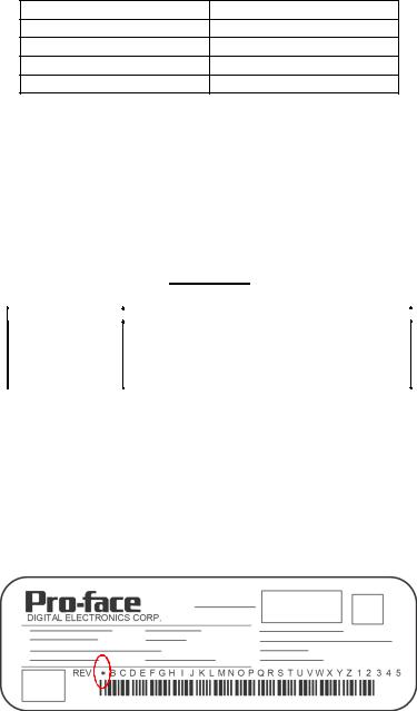
About Revision
The nameplate on the LT has the revision number of the LT. In the example below, the asterisk, which is placed at the “A”
position, shows that the revision number is “A”.
12
|
Contents |
|
Preface...................................................................................................................... |
1 |
|
Essential Safety Precautions..................................................................................... |
2 |
|
Information Symbols.................................................................................................. |
7 |
|
About the Manuals .................................................................................................... |
7 |
|
LT3000 Series Model Name Indication ..................................................................... |
8 |
|
LT3000 Series Model Names .................................................................................... |
8 |
|
Global Code .............................................................................................................. |
8 |
|
Package Contents ..................................................................................................... |
9 |
|
Installation prerequisites for standards.................................................................... |
10 |
|
CE Marking.............................................................................................................. |
12 |
|
KC Markings............................................................................................................ |
12 |
|
About Revision ........................................................................................................ |
12 |
|
Contents ................................................................................................................. |
13 |
|
Chapter 1 Overview |
|
|
1.1 |
System Design................................................................................................ |
1-2 |
|
1.1.1 LT-3200 Series...................................................................................................... |
1-2 |
|
1.1.2 LT-3300 Series...................................................................................................... |
1-4 |
1.2 |
Accessories .................................................................................................... |
1-6 |
|
1.2.1 USB Host Interface ............................................................................................... |
1-6 |
|
1.2.2 Serial Interface Item.............................................................................................. |
1-6 |
|
1.2.3 Option Items ......................................................................................................... |
1-7 |
|
1.2.4 Maintenance Items ............................................................................................... |
1-7 |
|
1.2.5 EX Module ............................................................................................................ |
1-8 |
1.3 Part Names and Functions ........................................................................... |
1-10 |
|
|
1.3.1 LT-3200 Series.................................................................................................... |
1-10 |
|
1.3.2 LT-3300 Series.................................................................................................... |
1-11 |
Chapter 2 Specifications |
|
|
2.1 |
LT-3200 Series................................................................................................ |
2-2 |
|
2.1.1 General Specifications .......................................................................................... |
2-2 |
|
2.1.2 Performance Specifications .................................................................................. |
2-4 |
|
2.1.3 Interface Specifications......................................................................................... |
2-6 |
|
2.1.4 Wiring to the DIO Connector............................................................................... |
2-12 |
|
2.1.5 Dimensions ......................................................................................................... |
2-14 |
2.2 |
LT-3300 Series.............................................................................................. |
2-17 |
|
2.2.1 General Specifications ........................................................................................ |
2-17 |
13
|
2.2.2 Performance Specifications ................................................................................ |
2-19 |
|
2.2.3 Interface Specifications....................................................................................... |
2-21 |
|
2.2.4 Wiring to the DIO Connector............................................................................... |
2-30 |
|
2.2.5 Dimensions ......................................................................................................... |
2-32 |
Chapter 3 Sample of the Circuit Diagrams |
|
|
3.1 |
Examples of Particular I/O Connections ......................................................... |
3-2 |
|
3.1.1 Connection to Pulse Motor Amplifier (CW/CCW type).......................................... |
3-2 |
|
3.1.2 Connection to Pulse Motor Amplifier (Clock Up/Down System) ........................... |
3-4 |
|
3.1.3 Connection to a Rotary Encoder........................................................................... |
3-6 |
Chapter 4 Installation and Wiring |
|
|
4.1 |
Installation....................................................................................................... |
4-2 |
4.2 |
Wiring Precautions.......................................................................................... |
4-7 |
|
4.2.1 Connecting the Power Cord.................................................................................. |
4-7 |
|
4.2.2 Connecting the Power Supply............................................................................. |
4-10 |
|
4.2.3 Grounding ........................................................................................................... |
4-11 |
|
4.2.4 Wiring Precautions.............................................................................................. |
4-12 |
|
4.2.5 Installation Precautions....................................................................................... |
4-13 |
4.3 |
USB Cable Clamp Attachment/Removal ...................................................... |
4-16 |
|
4.3.1 LT-3200 Series.................................................................................................... |
4-16 |
|
4.3.2 LT-3300 Series.................................................................................................... |
4-17 |
Chapter 5 Maintenance |
|
|
5.1 |
Cleaning the Display....................................................................................... |
5-2 |
5.2 |
Periodic Check Points..................................................................................... |
5-3 |
5.3 |
Replacing the Installation Gasket ................................................................... |
5-4 |
5.4 |
Replacing the Backlight .................................................................................. |
5-6 |
14

1 Overview
1.System Design
2.Accessories
3.Part Names and Functions
This chapter describes peripheral devices that can be connected to LT Series units along with the name and
functions of each part.
1-1

LT3000 Series Hardware Manual
1.1 System Design
1.1.1LT-3200 Series
The following diagram illustrates the standard range of items that can be connected to LT-3200 Series units.
LT RUN Mode Peripherals
LT Unit
(1)
|
Bar-Code Reader*1 |
USB-Serial (RS-232C) Conversion Cable |
(Commercial type) |
|
|
CA6-USB232-01 |
|
|
Bar-Code Reader*1 |
|
(Commercial type) |
USB-to-IEEE1284 |
Printer *1 |
Conversion Cable |
|
(Commercial type) |
(Commercial type) |
USB Cable |
|
FP-US00 or |
|
commercial type |
|
USB Front Cable |
|
(CA5-USBEXT-01) |
|
USB Hub (Commercial type) |
USB Memory Strage *1 |
|
(Commercial type) |
(2)
EX Module
(Up to two EX modules can be connected to the rear side of the LT-3201A.)
(3)
Various types of I/O equipment
Indicators, LEDs, sensors, switches, and so on
LT Interfaces
(1)USB Host Interface
(2)EX Module Interface
(3)DIO Interface
*1 For supported models, refer to Pro-face’s support site “Otasuke Pro!” (http://www.pro-face.com/otasuke/).
You can connect to this site by clicking the GP-Pro EX’s [Help (H)] menu – [Connect to Support Site- “Otasuke Pro!” (O)] command.
1-2
Chapter 1 Overview
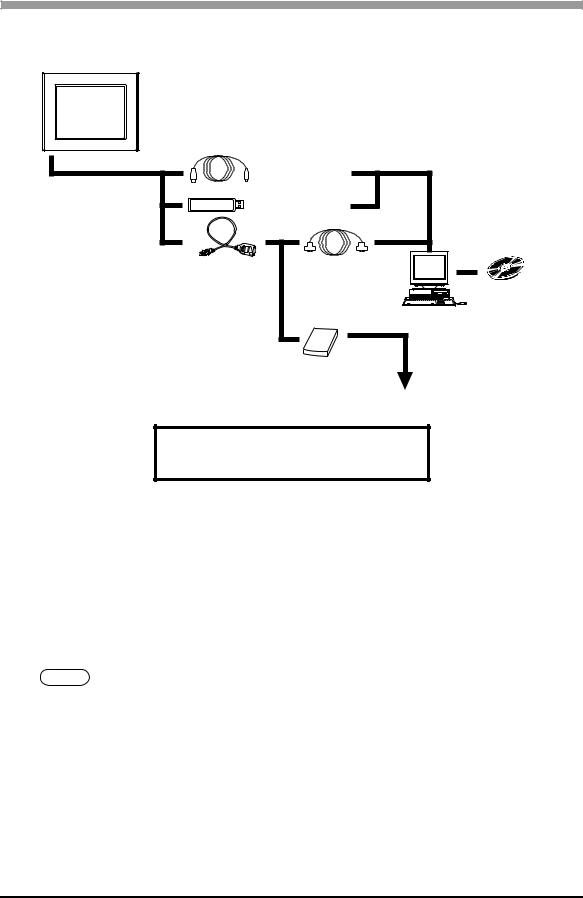
Edit Mode Peripherals
LT Unit
(1) |
USB Transfer Cable |
USB Port |
|
|
|
|
CA3-USBCB-01 |
|
|
USB Memory Strage *1 |
|
|
(Commercial type) |
|
|
|
Serial Port |
USB-Serial (RS-232C) |
RS-232C Cable*2 |
Conversion Cable |
(Prepared by user) |
CA6-USB232-01 |
|
Personal Computer *3 (Commercial type)
Modem*1 (Commercial type)
Telephone lines
Screen Editor
Software
GP-Pro EX
LT Interfaces
(1) USB Host Interface
*1 For supported models, refer to Pro-face’s support site “Otasuke Pro!” (http://www.pro-face.com/otasuke/).
You can connect to this site by clicking the GP-Pro EX’s [Help (H)] menu – [Connect to Support Site- “Otasuke Pro!” (O)] command.
*2 For details regarding connection methods, be sure to read “Transferring Projects and Data” under “ COM Transfer Connections” in the GP-Pro EX Reference Manual.
*3 Certain types and models of PCs cannot be used
SEE GP-Pro EX Reference Manual
1-3
LT3000 Series Hardware Manual
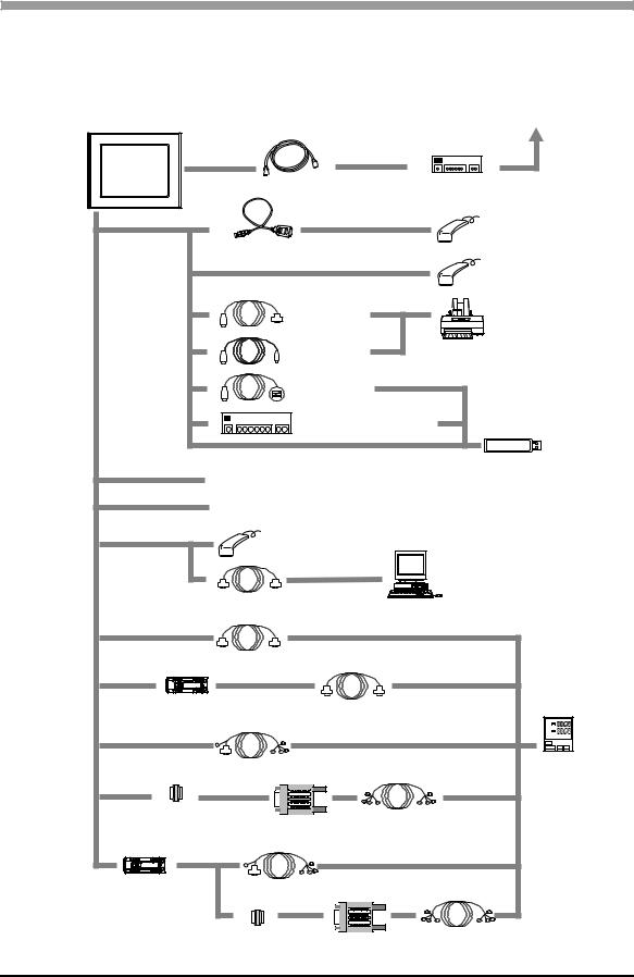
1.1.2LT-3300 Series
The following diagram illustrates the standard range of items that can be connected to LT-3300 Series units.
LT RUN Mode Peripherals
LT Unit |
|
|
|
|
|
To an Ethernet Network |
|
(1) |
|
|
|
|
|
|
|
Ethernet Cable(commercial type) |
|
Hub |
||
|
|
(commercial type) |
||||
|
|
|
|
|
||
(2) |
|
|
|
|
|
Bar-Code Reader*1 |
|
USB-Serial (RS-232C) Conversion Cable |
|
(Commercial type) |
|||
|
|
|
||||
|
CA6-USB232-01 |
|
|
|
Bar-Code Reader*1 |
|
|
|
|
|
|
|
|
|
|
|
|
|
|
(Commercial type) |
|
|
USB-to-IEEE1284 |
|
|
Printer *1 |
|
|
|
Conversion Cable |
|
|
||
|
|
(Commercial type) |
|
|
(Commercial type) |
|
|
|
|
|
|
||
|
|
USB Cable |
|
|
|
|
|
|
FP-US00 or |
|
|
|
|
|
|
commercial type |
|
|
|
|
|
|
USB Front Cable |
|
|
|
|
|
|
(CA5-USBEXT-01) |
|
|
|
|
|
|
USB Hub (Commercial type) |
USB Memory Strage *1 |
|||
|
|
(Commercial type) |
||||
|
|
|
|
|
|
|
(3) |
EX Module |
|
|
|
|
|
|
|
|
|
|
||
(4) |
(Up to 3 EX modules can be connected to the rear side of the LT-3300 series) |
|||||
Various types of I/O equipment |
|
|
|
|||
|
|
|
|
|||
|
Indicators, LEDs, sensors, switches, and so on |
|
|
|||
(5) |
|
Bar-Code Reader*1 |
|
|
|
|
|
|
|
|
|
||
|
|
(Commercial type) |
|
|
|
|
|
|
|
|
|
|
Mouse Emulator |
|
|
|
|
|
|
(Commercial type) |
|
RS-232C Cable |
|
|
|
|
|
|
CA3-CBL232/5M-01 |
|
|
|
|
|
(5) |
|
|
|
|
|
(7) |
|
RS-232C Cable |
|
|
|
|
|
(5) |
CA3-CBL232/5M-01 |
|
|
|
(7) |
|
|
|
|
|
|
||
|
RS-232C Isolation Unit |
RS-232C Cable |
|
|
||
|
CA3-ISO232-01 |
|
|
|
||
|
|
CA3-CBL232/5M-01 |
|
|
||
|
Switch setting:RS-232C |
|
|
|||
(6) |
|
|
|
(8) |
||
|
|
|
|
|
||
|
RS-422 Cable |
|
|
|
Temperature Controllers |
|
|
|
|
|
Various Boards, such as |
||
|
CA3-CBL422/5M-01 |
|
|
|
||
(6) |
|
|
|
(8) Memory Link |
||
|
|
|
|
|
||
|
COM Port |
|
|
RS-422 Cable |
|
|
|
Conversion Adapter |
Terminal Block |
|
|||
|
CA3-ADPCOM-01 |
Conversion Adapter |
(Prepared by user) |
|||
|
|
|
|
|||
|
|
CA3-ADPTRM-01 |
|
|
|
|
(6) |
|
|
|
|
|
(8) |
RS-232C Isolation Unit |
RS-422 Cable |
|
|
|
|
|
CA3-ISO232-01*2,*3 |
|
|
|
|
||
CA3-CBL422/5M-01 |
|
|
|
|||
Switch setting:RS-422 |
|
|
(8) |
|||
|
|
|
|
|||
|
|
COM Port |
Terminal Block |
RS-422 Cable |
||
|
|
Conversion Adapter |
||||
|
|
CA3-ADPCOM-01 |
Conversion Adapter |
(Prepared by user) |
||
CA3-ADPTRM-01
1-4

|
|
|
Chapter 1 Overview |
|
|
|
|
|
|
|
|
|
|
|
|
LT Interfaces |
Temperature Controller (etc.) Interfaces |
|
|
|
(1) |
Ethernet Interface |
(7) RS-232C Port |
|
|
|
(10BASE-T/100BASE-TX) |
(8) RS-422 Port |
|
|
|
Not available with LT-3301L units |
|
|
|
(2) |
USB Host Interface |
|
|
|
(3) |
EX Module Interface |
|
|
|
(4) |
DIO Interface |
|
|
|
(5) |
Serial Interface (COM1) |
|
|
|
|
(RS-232C mode) |
|
|
|
(6) |
Serial Interface (COM1) |
|
|
|
|
(RS-422 mode) |
|
|
*1 For supported models, refer to Pro-face’s support site “Otasuke Pro!” (http://www.pro-face.com/otasuke/).
You can connect to this site by clicking the GP-Pro EX’s [Help (H)] menu – [Connect to Support Site- “Otasuke Pro!” (O)] command.
*2 The RS-232C Isolation Unit does not correspond to RS-422/485 (2 wire) communication. *3 The RS-232C Isolation Unit does not correspond to Serial Multilink communication.
Edit Mode Peripherals
LT Unit |
To an Ethernet Network |
(1) |
(2) |
USB Transfer Cable |
USB Port |
|
|
|
|
CA3-USBCB-01 |
|
|
USB Memory Strage *1 |
|
|
(Commercial type) |
|
|
|
Serial Port |
RS-232C Cable*2
USB-Serial (RS-232C) (Prepared by user)
Conversion Cable
CA6-USB232-01
Personal Computer *3 (Commercial type)
Modem*1 (Commercial type)
Telephone lines
Screen Editor
Software
GP-Pro EX
LT Interfaces
(1)Ethernet Interface (10BASE-T/100BASE-TX)
Not available with LT-3301L units
(2)USB Host Interface
*1 For supported models, refer to Pro-face’s support site “Otasuke Pro!” (http://www.pro-face.com/otasuke/).
You can connect to this site by clicking the GP-Pro EX’s [Help (H)] menu – [Connect to Support Site- “Otasuke Pro!” (O)] command.
*2 For details regarding connection methods, be sure to read “Transferring Projects and Data” under “ COM Transfer Connections” in the GP-Pro EX Reference Manual.
*3 Certain types and models of PCs cannot be used
SEE GP-Pro EX Reference Manual
1-5
LT3000 Series Hardware Manual
1.2 Accessories
All accessories listed here are produced by Digital Electronics Corporation.
1.2.1USB Host Interface
Product Name |
Model No. |
Description |
|
|
|
|
|
USB Transfer Cable |
CA3-USBCB-01 (2m) |
Downloads project data created with the |
|
Screen Editor via the LT unit’s USB I/F. |
|||
|
|
||
|
|
|
|
USB Cable |
FP-US00 (5m) |
Connects a USB printer. (TYPE-B) |
|
|
|
|
|
USB Front Cable |
CA5-USBEXT-01 (1m) |
Extension cable attaching USB port to |
|
front panel. |
|||
|
|
||
|
|
|
|
|
|
Cable for converting a LT unit's USB |
|
|
|
interface into a serial interface (RS-232C). |
|
USB-Serial (RS-232C) |
|
Allows connection to modems*1 or |
|
CA6-USB232-01 (0.5m) |
barcode readers*1 that support RS-232C. |
||
Conversion Cable |
|||
|
Can be used to transfer project data |
||
|
|
||
|
|
created with the Screen Editor via a serial |
|
|
|
interface.*2 |
*1 For supported models, refer to Pro-face’s support site “Otasuke Pro!” (http://www.pro-face.com/otasuke/).
You can connect to this site by clicking the GP-Pro EX’s [Help (H)] menu - [Connect to Support Site “Otasuke Pro!” (O)] command.
*2 Requires an RS-232C cable (prepared by user) for connection. For details regarding system design, refer to Edit Mode Peripherals (page-3) if using LT-3200; refer to Edit Mode Peripherals (page-5) if using LT-3300.
For instructions on how to connect between USB-Serial (RS-232C) Conversion Cable and your PC, always refer to the "GP-Pro EX Reference Manual -> Transferring Projects and Data -> COM Transfer Connections".
1.2.2Serial Interface Item
Product Name |
Model No. |
Description |
|
|
|
|
|
|
|
Interface cable for communication between a |
|
RS-232C Cable |
CA3-CBL232/5M-01 (5m) |
temperature controller/various boards and the |
|
|
|
LT-3300 series via RS-232C. |
|
|
|
|
|
|
|
Interface cable for communication between a |
|
RS-422 Cable |
CA3-CBL422/5M-01 (5m) |
temperature controller/various boards and the |
|
|
|
LT-3300 series via RS-422. (Socket Type) |
|
|
|
|
|
|
|
Interface cable for communication between a |
|
RS-422 Cable |
CA3-CBL422-01 (5m) |
temperature controller/various boards and the |
|
|
|
LT-3300 series via RS-422. (Plug Type) |
|
|
|
|
|
|
|
Unit for providing isolated connection between a |
|
RS232C |
CA3-ISO232-01 |
temperature controller/various boards and the |
|
Isolation Unit |
LT-3300 series. |
||
|
|||
|
|
RS-232C and RS-422 are switchable. |
|
|
|
|
|
COM Port Conversion |
CA3-ADPCOM-01 |
Connects optional RS-422 communication items |
|
Adapter |
|
to LT-3300 series unit’s COM1 port. |
|
Terminal Block |
CA3-ADPTRM-01 |
Connects output from a serial interface with an |
|
Conversion Adapter |
RS-422 terminal block. |
||
|
|||
|
|
|
1-6

|
|
|
|
Chapter 1 Overview |
|
|
|
|
|
1.2.3 |
Option Items |
|
|
|
|
|
|
|
|
|
Product Name |
Model No. |
Corresponding LT |
Description |
|
|
|
|
|
|
Screen Protection |
CA6-DFS4-01 |
LT-3200 Series |
Disposable, dirt-resistant sheet |
|
|
|
for the LT unit’s screen. |
|
|
Sheet |
CA3-DFS6-01 |
LT-3300 Series |
|
|
(5 sheets/set) (Hard type) |
|||
|
|
|
|
|
|
|
|
|
|
|
|
|
|
The installation of the cover is |
|
|
|
|
to protect Display from leaking |
|
Proective Cover |
CA4-DCMDL-01 |
LT-3300 Series |
liquid and raise resistant |
|
|
|
|
performance against chemical |
|
|
|
|
substance (5 sheets) |
|
|
|
|
|
1.2.4Maintenance Items
Product Name |
Model No. |
Corresponding LT |
Description |
|
|
|
|
|
|
Installation |
CA3-ATFALL-01 |
LT3000 Series |
Used to install the LT into a solid |
|
Fastener |
panel. |
|||
|
|
|||
|
|
|
|
|
Installation Gasket |
ST400-WP01 |
LT-3200 Series |
Provides dust and moisture resistance |
|
|
|
when LT is installed into a solid panel. |
||
CA3-WPG6-01 |
LT-3300 Series |
|||
|
||||
|
|
|
|
|
|
CA6-DIOCN4-01 |
LT-3200 Series |
Connector attached to the DIO |
|
DIO Connector |
|
|
interface. Connects an external I/O |
|
CA7-DIOCN5-01 |
LT-3300 Series |
|||
|
device. (Set of 5 connectors) |
|||
|
|
|
|
|
USB Cable Clamp |
CA5-USBATL-01 |
LT-3200 Series |
USB Cable clamp to prevent |
|
|
|
disconnection. |
||
CA7-USBAT6-01 |
LT-3300 Series |
|||
|
||||
|
|
|
|
|
DC Power Supply |
|
|
Connector for attaching power supply |
|
Connector for |
CA5-DCCNM-01 |
LT3000 Series |
||
to medium-sized units. |
||||
Medium-sized Units |
|
|
||
|
|
|
||
|
|
|
|
|
EX Module |
CA7-FIXEXM-01 |
LT-3300 Series |
Hook for securing three EX modules |
|
Securing Hook |
to the LT-3300 Series. |
|||
|
|
|||
|
|
|
|
|
Panel Cutout |
CA4-ATM5-01 |
LT-3300 Series |
Panel cutout adapter for mounting LT- |
|
Adapter |
3300 Series in cutout of LT Series. |
|||
|
|
|||
|
|
|
|
1-7

LT3000 Series Hardware Manual
1.2.5EX Module
(Expanded I/O Unit for LT3000 Series use)
Up to two EX modules can be connected to the rear side of the LT-3200 series.
Up to three EX modules can be connected to the rear side of the LT-3300 series.
• As for EXM-DMM24DRF and EXM-ARI8LT, only one EX module can be connected to an LT.
For the details, please read “EX Module Hardware Manual” downloaded from Pro-face's support
site “Otasuke Pro!” (http://www.pro-face.com/otasuke/).
Standard Input Module
Product Name |
Model No. |
Description |
|
|
|
|
|
EX module (8-point input module) |
EXM-DDI8DT |
8-point sink/source shared I/O Unit. |
|
DC24V input signal can be connected. |
|||
|
|
||
|
|
|
|
EX module (16-point input module) |
EXM-DDI16DT |
16-point sink/source shared I/O Unit. |
|
DC24V input signal can be connected. |
|||
|
|
||
|
|
|
Standard Output Module
Product Name |
Model No. |
Description |
|
|
|
|
|
EX module |
EXM-DRA8RT |
8-point relay output/2 common type |
|
(8-point relay-output module) |
I/O Unit. |
||
|
|||
|
|
|
|
EX module |
EXM-DRA16RT |
16-point relay output/2 common type |
|
(16-point relay-output module) |
I/O Unit. |
||
|
|||
|
|
|
|
EX module |
EXM-DDO8UT |
8-point transistor output sink I/O Unit. |
|
(8-point sink-output module) |
|||
|
|
||
|
|
|
|
EX module |
EXM-DDO8TT |
8-point transistor output source I/O |
|
(8-point source-output module) |
Unit. |
||
|
|||
|
|
|
|
EX module |
EXM-DDO16UK |
16-point transistor output sink I/O Unit. |
|
(16-point sink-output module) |
|||
|
|
||
|
|
|
|
EX module |
EXM-DDO16TK |
16-point transistor output source I/O |
|
(16-point source-output module) |
Unit. |
||
|
|||
|
|
|
Standard I/O Module
Product Name |
Model No. |
Description |
|
|
|
|
|
EX module (4-point inputs/4-point |
EXM-DMM8DRT |
4-point input sink-source/4-point relay- |
|
relay-output module) |
output/1 common type I/O Unit. |
||
|
|||
|
|
|
|
EX module (16-point inputs/8-point |
EXM-DMM24DRF |
16-point input sink-source/8-point |
|
relay-output module) |
relay-output/1 common type I/O Unit. |
||
|
|||
|
|
|
1-8

|
|
|
Chapter 1 Overview |
|
|
|
|
|
Analog Input Module |
|
|
|
|
|
|
|
Product Name |
Model No. |
Description |
|
|
|
|
|
EX module |
|
2-ch analogue Input Unit. |
|
EXM-AMI2HT |
(Voltage DC0 to 10V / Current DC4 to |
|
|
(2-ch analogue-input module) |
||
|
|
20mA) |
|
|
|
|
|
|
|
|
|
|
EX module |
|
4-ch temperature Input Unit. |
|
|
(Voltage DC0 to 10V / Current DC4 to |
|
|
(4-ch Analog input / Temperature input |
EXM-AMI4LT |
|
|
20mA) |
||
|
module) |
|
|
|
|
Pt100/Pt1000/Ni100/Ni1000 |
|
|
|
|
|
|
|
|
|
|
EX module |
EXM-ARI8LT |
8-ch temperature Input Unit. |
|
(8-ch Pt100/Pt1000 input module) |
Pt100/Pt1000 |
|
|
|
||
|
|
|
|
|
Analog Output Module |
|
|
|
|
|
|
|
Product Name |
Model No. |
Description |
|
|
|
|
|
EX module |
|
1-ch analogue Output Unit. |
|
EXM-AMO1HT |
(Voltage DC0 to 10V / Current DC4 to |
|
|
(1-ch analogue-output module) |
||
|
|
20mA) |
|
|
|
|
|
|
|
|
|
|
EX module |
EXM-AVO2HT |
2-ch analogue Output Unit. |
|
(2-ch analogue-output module) |
(Voltage DC-10 to +10V ) |
|
|
|
||
|
|
|
|
|
Analog I/O Module |
|
|
|
|
|
|
|
Product Name |
Model No. |
Description |
|
|
|
|
|
|
|
2-ch temperature Input/1-ch analogue |
|
EX module (Thermocouple Pt100 |
|
Output Unit. |
|
EXM-ALM3LT |
Pt100 Input |
|
|
input/1-ch analogue-output module) |
||
|
|
(Voltage Output DC0 to 10V / Current |
|
|
|
|
|
|
|
|
Output DC4 to 20mA) |
|
|
|
|
|
|
|
2-ch analogue Input/1-ch analogue |
|
EX module (2-ch analogue-input/1-ch |
EXM-AMM3HT |
Output Unit. |
|
analogue-output module) |
(Voltage I/O DC0 to 10V / Current I/O |
|
|
|
||
|
|
|
DC4 to 20mA) |
|
|
|
|
|
|
|
4-ch analogue Input/2-ch analogue |
|
EX module (4-ch analogue-input/2-ch |
EXM-AMM6HT |
Output Unit. |
|
analogue-output module) |
(Voltage I/O DC0 to 10V / Current I/O |
|
|
|
||
|
|
|
DC4 to 20mA) |
|
|
|
|
1-9

LT3000 Series Hardware Manual
1.3 Part Names and Functions
1.3.1LT-3200 Series
A
Front
B C
Back
E F
D
Bottom
A: Status LED
This LED indicates the LT’s status, e.g. power input, firmware RUN status or backlight condition. Also, indicates the status of logic program execution.
|
|
Operation |
Logic execu- |
|
|
|
tion mode |
||
Color |
Indicator |
Mode |
||
(when logic is |
||||
|
|
(Drawing) |
||
|
|
enabled) |
||
|
|
|
||
|
|
|
|
|
|
|
OFFLINE |
- |
|
|
ON |
|
|
|
|
In |
RUN |
||
Green |
|
operation |
||
|
|
|||
|
|
|
|
|
|
Flashing |
In |
STOP |
|
|
operation |
|||
|
|
|
||
|
|
|
|
|
|
ON |
When power |
is turned on. |
|
Red |
|
|
|
|
Flashing |
In |
Major Error |
||
|
operation |
|||
|
|
|
||
|
|
|
|
|
Orange |
ON |
Backlight |
burnout |
|
|
|
|
||
Flashing |
During software startup |
|||
|
||||
|
|
|
|
|
B:AUX Unit Interface/Expansion Unit (EXT2)
Interface where additional units such as communication devices can be connected.
C:EX Module Interface (EXT1)
This is the interface to mount the Pro-face’s EX module.
D:Power Plug Connector
E:USB Host Interface (USB)
Conforms to USB1.1. (TYPE-A conn.) Power Supply Voltage: DC5V ± 5% Output Current: 500mA (at maximum)
Connects a data transfer cable or USB-compatible printer. The maximum communication distance is 5m.
F:DIO Interface (DIO)
This is the interface to mount external I/O equipment using the DIO connector.
1-10
Chapter 1 Overview
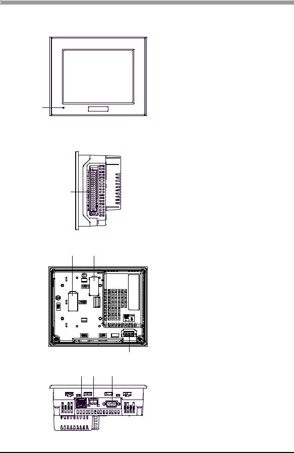
1.3.2LT-3300 Series
A
Front
B
Right side
C D
E |
Back |
F G H
Bottom
A: Status LED
This LED indicates the LT’s status, e.g. power input, firmware RUN status or backlight condition. Also, indicates the status of logic program execution.
|
|
Operation |
Logic execu- |
|
|
|
tion mode |
||
Color |
Indicator |
Mode |
||
(when logic is |
||||
|
|
(Drawing) |
||
|
|
enabled) |
||
|
|
|
||
|
|
|
|
|
|
|
OFFLINE |
- |
|
|
ON |
|
|
|
|
In |
RUN |
||
Green |
|
operation |
||
|
|
|||
|
|
|
|
|
|
Flashing |
In |
STOP |
|
|
operation |
|||
|
|
|
||
|
|
|
|
|
|
ON |
When power |
is turned on. |
|
Red |
|
|
|
|
Flashing |
In |
Major Error |
||
|
operation |
|||
|
|
|
||
|
|
|
|
|
Orange |
ON |
Backlight |
burnout |
|
|
|
|
||
Flashing |
During software startup |
|||
|
||||
|
|
|
|
|
B: DIO Interface (DIO)
This is the interface to mount external I/O equipment using the DIO connector.
C:AUX Unit Interface/Expansion Unit (EXT2)
Interface where additional units such as communication devices can be connected.
D:EX Module Interface (EXT1)
This is the interface to mount the Pro-face’s EX module.
E:Power Plug Connector
F:Ethernet Interface (10BASE-T/100BASE-TX)
The Ethernet transmission interface (10BASE-T/ 100BASE-TX). An RJ-45 type modular jack connector (8-pole) is used. The LED turns on or off to indicate the current status.
LED |
Indicates |
|
Green ON |
Data transmission available |
|
|
|
|
Green OFF |
No connection or subsequent |
|
transmission failure |
||
|
||
Yellow ON |
Data transmission is |
|
occurring. |
||
|
||
Yellow OFF |
No data transmission |
|
|
|
G:USB Host Interface (USB)
Conforms to USB1.1. (TYPE-A conn.) Power Supply Voltage: DC5V ± 5% Output Current: 500mA (at maximum)
Connects a data transfer cable or USB-compatible printer. The maximum communication distance is 5m.
H:Serial Interface (COM1)
RS232C/RS422/RS485 serial interface. D-sub 9- pin plug type connector. Communication method is switched via software.
1-11

LT3000 Series Hardware Manual
1-12

2 Specifications
1.LT-3200 Series
2.LT-3300 Series
This chapter describes the general, functional and interface specifications of the LT as well as its part names
and dimensions.
2-1
Loading...