

Page 1

*36HULHV
+DUGZDUH0DQXDO
Page 2

Preface
Thank you for purchasing Pro-face’s GP-4100 Series Programmable Operator Interface (Hereafter referred to as the “GP
unit”).
Before operating your GP unit, be sure to read this manual to familiarize yourself with the GP unit’s operation procedures
and features.
NOTICE
1. Copying this manual’s contents, either in whole or in part, is prohibited wi thout the express permission of Digital
Electronics Corporation, Japan.
2. The information contained in this manual is subject to change without notice.
3. If you should you find any errors or omissions in this document, please contact Digital Electronics Corporation to
report your findings.
4. Regardless of Clause 3 above, Digital Electronics Corporation shall not be held responsible for any damages,
losses or third-party damages resulting from the use of this product.
Copyright
Product names used in this manual are the trademarks / registered trademarks of their respective owners.
© 2012.11 Digital Electronics Corporation. All Rights Reserved.
1
Page 3

Essential Safety Precautions
All safety-related procedures stated in this document must be followed to operate the GP correctly and safely. Be sure to
read this and any related documents thoroughly to understand the correct operation and functions of the GP unit.
Safety Icons
Throughout this manual, these icons provide essential safety information for GP operation procedures requiring special
attention. These icons indicate the following levels of danger:
DANGER
DANGER indicates an imminently hazardous situation which, if not avoided,
will result in death or serious injury.
WARNING
WARNING indicates a potentially hazardous situation which, if not avoided,
can result in death or serious injury.
CAUTION
CAUTION indicates a potentially hazardous situation which, if not avoided,
can result in minor or moderate injury.
CAUTION
CAUTION, used without the safety alert symbol, indicates a potentially haz-
ardous situation which, if not avoided, can result in equipment damage.
2
Page 4

WARNING
HAZARD OF ELECTRIC SHOCK, EXPLOSION OR ARC FLASH
• NEVER touch a live power terminal. Doing so could cause an electrical shock or a machine malfunction.
• Do not use voltage beyond the GP unit's specified range. Doing so may cause a fire or an electric shock.
• Do not disassemble or modify the GP unit. Doing so may cause a fire or an electric shock.
• Do not operate the GP in an environment where flammable gases are present since it may cause an
explosion.
• Do not allow water, liquids or metal fragments to enter inside the GP unit’s case, since they can cause
either a malfunction or an electric shock. The allowable pollution degree is 2.
• To prevent electrical shock or equipment damage, unplug the GP unit's power cord from the power supply
prior to installing or wiring the GP.
• The GP unit's wiring should be checked to confirm that both the operating voltage and wiring terminal
locations are correct. If either the voltage or the wiring terminal location is incorrect, it can cause a fire or
accident.
• Be sure to use only the designated torque to tighten the GP unit's terminal block screws. If these screws
are not tightened firmly, it may cause a short-circuit, fire or incorrect unit operation.
• Be sure that metal particles and wiring debris do not fall inside the GP unit. They can cause a fire, malfunction or incorrect unit operation.
• To prevent an electric shock, be sure to disconnect your GP unit's power cord from the power supply
before wiring the GP.
• Be sure to ground the GP unit's FG wire separately from other equipment FG lines. Also, be sure to use a
2
grounding resistance of 100Ω or less and a 2mm
standard. Otherwise, electric shock or malfunctions may result.
• To prevent an electrical shock, unplug the GP unit's power cord before either cleaning the GP or attaching/
detaching the power terminal attachment screws.
• Do not connect or disconnect Host and GP unit communication cab les while the GP is turned ON.
Failure to follow these instructions will result in death or serious injury, or unintended equipment
damage.
(14 AWG) or thicker wire, or your country’s applicable
3
Page 5

WARNING
UNINTENDED EQUIPMENT OPERATION OR LOSS OF CONTROL
• Do not make switches using the switches on the touch panels which may cause operator injury and
machine damage. An output may remain either ON or OFF and a major accident can occur. To prevent
this, set up circuits such as limiters that will monitor vital output signals. Design switches for important
operations to be performed by separate devices. An incorrect output or malfunction can occur and thereby
cause an accident.
• Do not create GP touch panel switches to control machine safety operations, such as an emergency stop
switch. Install these switches as separate hardware switches, otherwise severe bodily injury or equipment
damage can occur.
• Do not use the GP as a warning device for critical alarms that can cause serious operator injury, machine
damage or can halt system operation. Critical alarm indicators and their control/activator units must be
designed using stand-alone hardware and/or mechanical interlocks.
• Be sure to design your system so that a communication interruption between the GP and its host controller
will not cause equipment to malfunction. This is to prevent any possibil ity of bodily injury or equipment
damage.
• Do not use the GP with aircraft control devices, aerospace equipment, central trunk data transmission
(communication) devices, nuclear power control devices, or medical life support equipment, due to these
devices' inherent requirements of extremely high levels of safety and reliability.
• When using the GP with transportation vehicles (trains, cars, and ships), disaster and crime prevention
devices, various types of safety equipment, and medical devices that are not life-support related, use
redundant and/or failsafe system designs to ensure proper reliability and safety.
• After the GP unit's backlight burns out the touch panel is still active, unlike the GP unit's "Standby Mode".
If the operator fails to notice that the backlight is burned out and touches the panel, a potentially dangerous machine operation error can occur. Therefore, do not create GP unit touch panel switches that may
cause injury and/or equipment damage. If your GP unit's backlight suddenly turns OFF, use the following
steps to determine if the backlight is actually burned out.
1) If the GP unit's "Backlight Control" is not set and the screen has gone blank, your backlight is
burned out.
2) If the GP unit's "Backlight Control" is set to Standby Mode and the screen has gone blank, and
touching the screen or performing another input operation does not cause the display to reappear,
your backlight is burned out.
• To prevent a GP unit malfunction due to excessive noise, isolate all GP input/output signal lines from all
power wiring or power cables via a separate wiring duct.
Failure to follow these instructions will result in death or serious injury, or unintended equipment
damage.
4
Page 6

WARNING
UNINTENDED EQUIPMENT OPERATION OR LOSS OF CONTROL
• The cables connected to the GP should be secured by cable clamps to prevent weight or tension of the
cables added to the connectors or terminals.
• Be sure all cable connectors are securely attached to the GP unit. A loose connection may cause incorrect input or output signals.
• Do not press on the GP unit’s display with excessive force or with a hard object, since it can damage the
display. Also, do not press on the touch panel with a pointed object, such as the tip of a mechanical pencil
or a screwdriver, since doing so can damage the touch panel.
• Do not install the GP where the ambient temperature exceeds the specified range. Doing so may cause a
unit malfunction.
• To prevent abnormally high temperatures from occurring inside the GP, do not restrict or block the GP
unit's rear-face ventilation slots.
• Do not operate the GP in areas where large, sudden temperature changes can occur. These changes can
cause condensation to form inside the GP, possibly causing it to malfunction.
• Do not operate or store the GP in locations where it can be exposed to direct sunlight, high temperatures,
excessive dust, moisture or vibration.
• Do not operate or store the GP where chemicals evaporate, or where chemicals are present in the air.
Corrosive chemicals: Acids, alkalines, liquids containing salt
Flammable chemicals: Organic Solvents
• Do not use paint thinner or organic solvents to remove dirt or oil from the GP unit's surface. Instead, use a
soft cloth moistened with a diluted neutral detergent.
• Do not use or store the GP in areas with direct sunlight, since the sun's ultraviolet rays may cause the
LCD's quality to deteriorate.
• Do not store the GP in an area where the temperature is lower than that recommended in the GP unit's
specifications. Doing so may cause the LCD display's liquid to congeal, which can damage the LCD.
Also, if the storage area's temperature becomes higher than the specified level, the LCD's liquid may
become isotropic, causing irreversible damage to the LCD. Therefore, only store the GP in areas where
temperatures are within the GP unit's specifications.
• After turning OFF the GP, be sure to wait a few seconds before turning it ON again. The GP may not operate correctly if it is restarted too quickly.
Failure to follow these instructions will result in death or serious injury, or unintended equipment
damage.
5
Page 7

CAUTION
EYE IRRITANT
• The unit's liquid crystal panel contains a powerful irritant. If, for any reason, the panel is damaged and this
liquid enters your eyes, flush your eyes for 15 minutes with running water and contact a physician immediately.
Failure to follow the instruction can result in injury.
CAUTION
LOSS OF DATA
• Be sure to back up the GP screen data in case they are lost accidentally.
Failure to follow the instruction can result in loss of data.
CAUTION
PROPER EQUIPMENT DISPOSAL REQUIREMENTS
• The unit should be disposed of in a manner appropriate to, and in accordance with, the user country's
industrial machinery disposal standards.
Failure to follow the instruction can result in equipment or environment damage.
6
Page 8

LCD Panel Usage Precautions
• The LCD panel’s liquid contains an irritant. If the panel is damaged and any of this liquid contacts your skin,
immediately rinse the area with running water for at least 15 minutes. If the liquid gets in your eyes, immediately
rinseyour eyes with running water for at least 15 minutes and consult a doctor.
• The GP unit’s LCD screen may flicker or show unevenness in the brightness of certain images or at some contrast
settings. This is an LCD characteristic and not a product defect.
• There’s an individual dif ference in brightness and tone of LCD screen. Please be aware of this difference before using
the lined-up plural units.
• Depending on the ambient temperature, LCD displays may sometimes look whitish (at high temperatures) or blackish
(at low temperatures). This is an LCD characteristic and not a product defect.
• Some of GP unit’s LCD screens may contain light or dark pixels. This is an LCD characteristic and not a product
defect.
• Extended shadows, or “Crosstalk” may appear on the sides of screen images. This is an LCD characteristic and not a
product defect.
• The color displayed on the GP unit’s LCD screen may appear different when seen from outside the specified viewing
angle. This is an LCD characteristic and not a product defect.
• When the same image is displayed on the GP unit’s screen for a long period, an afterimage may appear when the image
is changed. This is an LCD characteristic and not a product defect.
• To prevent an afterimage:
* Set the GP unit’s display OFF feature when you plan to display the same screen image for a long period of time.
* Change the screen image periodically and try to not display the same image for a long period of time.
• Please be aware that characteristics of the GP unit’s LCD screen with a white/red LED backlight may change gradually
owing to the deterioration of the backlight LED. The white LCD display may look bluish when it turns on.
7
Page 9

About the Manuals
For the detailed information on GP-4100 Series, refer to the following manuals.
• Maintenance/Troubleshooting
For the Offline Settings, see Maintenance/Troubleshooting (Offline Settings Guide).
• GP-Pro EX Device/PLC Connection Manual
• GP-Pro EX Reference Manual
The manuals can be downloaded from Pro-face Home Page “Otasuke Pro!”.
URL “Otasuke Pro!”
http://www.pro-face.com/otasuke/
Information Symbols
This manual uses the following icons:
Indicates a warning or a product limitation. Be sure to follow the instructions given with
this icon to ensure the safe operation of the GP.
Screen Editor Indicates the GP-Pro EX software.
PLC Abbreviation for Programmable Logic Controller.
* Indicates useful or importan t supplemental information.
Contains additional or useful information.
SEE
Indicates pages containing related information.
8
Page 10

Model name
GP-4100 Series Model Name Indication
G P 41
A 1 GP-4100 Series (3.4-inch, 200 x 80 dots)
B 0 Normal resolution
C
D
E D DC24V type power supply is used.
0 * * 1
ABC ED
4 Ethernet type
5 RS-232C type
6 RS-422/485 type
7 RS-485 (isolation) type
G STN Monochrome Green/Orange/Red
W STN Monochrome White/Pink/Red
D
GP-4100 Series Model Names
Series Names Models
GP-4104
GP4104G1D
GP4104W1D
GP-4105
GP4000 Series GP-4100 Series
GP-4106
GP-4107
GP4105G1D
GP4105W1D
GP4106G1D
GP4106W1D
GP4107G1D
GP4107W1D
Global Code
A global code is assigned to every Pro-face product as a universal model number.
For more information on product models and their matching global codes, please refer to the following URL.
http://www.pro-face.com/product/globalcode.html
9
Page 11

Package Contents
The following items are included in the GP unit’s package . Before using t he GP, please check that all items listed her e are
present.
GP Unit: 1
COM I/F Connector (1)
(For RS-232C and
RS-422/485 types)
(Attached to the GP unit)
*1 Not included with models that have the following type of power connector.
• English and
Japanese Installation
Guide (1)
• Warning/Caution
Information (1)
DC Power Supply
Connector (1)
(For the Ethernet
type and a portion of
models
(Attached to the GP
unit)
*1
)
Installation Gasket: 1
(Attached to the GP unit)
Installation Fasteners:
Set of 2
This unit has been carefully packed, with special attention to quality. However, should you find anything damaged or
missing, please contact your local GP distributor immediately .
10
Page 12

• UL listed products
UL/c-UL Approval
Industrial Control Equipment refer to UL508
Suitable for use in Class I, Division 2,
Groups A, B, C, and D Hazardous
(classified) locations, or NonHazardous Locations.
• c-UL listed products
Process Control Equipment
Suitable for use in Class I, Division 2,
Groups A, B, C, and D Hazardous
(classified) locations, or NonHazardous Locations.
• Product List
Product Model No.
GP4104G1D 3910017-11 9999
GP4104W1D 3910017-12 9999
GP4105G1D 3910017-01 9 - 9 -
GP4105W1D 3910017-02 9 - 9 -
GP4106G1D 3910017-03 9 - 9 -
GP4106W1D 3910017-04 9 - 9 -
GP4107G1D 3910017-05 9 - 9 -
GP4107W1D 3910017-06 9 - 9 -
Registration Model
No.
ANSI/ISA12.12.01
refer to CSA-C22.2
No.142
refer to CSA-C22.2
No.213
UL c-UL
[a] [b] [c] [d]
see [a] in the
“Product List“
see [b] in the
“Product List“
see [c] in the
“Product List“
see [d] in the
“Product List“
UL/c-UL File No.: E220851, E210412
<Cautions>
Be aware of the following items when building the GP into an end-use product:
• For use on a flat surface of a Type 4X (Indoor Use Only) and/or Type 13 Enclosure.
<Compliance and Handling Cautions in Hazardous Locations>
(1) Suitable for use in Class I, Division 2, Groups A, B, C, and D Hazardous Locations, or Non-Hazardous
Locations Only.
(2) W ARNING: Explosion hazard-substitution of any components may impair suitability for Class I, Division 2
(3) WARNING: Explosion hazard-do not disconnect equipment while the circuit is live or unless the area is
known to be free of ignitable concentrations.
11
Page 13
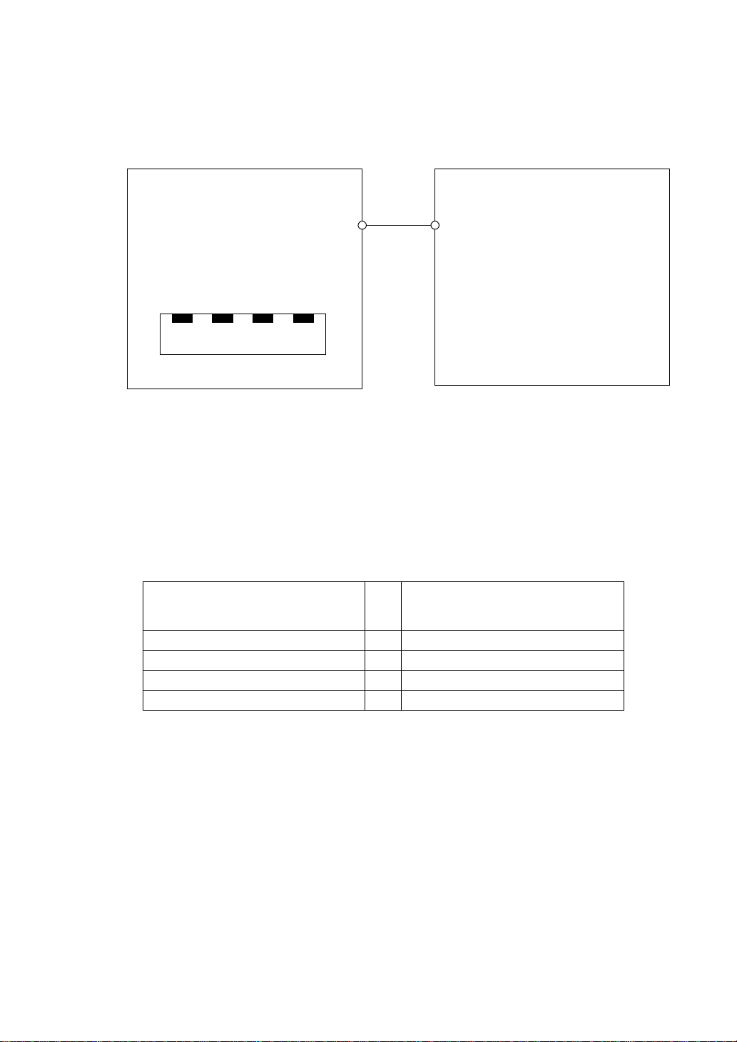
(4) Control Drawing of USB (Type A) Interface (USB1)
The information below concerns the use of the USB interface used in Class I, Division 2, Groups A, B, C,
and D hazardous locations (from Doc No. 3910017-USB).
USB Pin Description
1. Vcc
2. D-
3. D+
4. GND
(See Note 1 for details)
Shield GND
1 2 3 4
Notes:
1. Nonincendive Circuit Parameters:
USB interface:
Voc = 5.25 V
Isc = 0.7 A
Ca = 16 µF
La = 10 µH
2. Selected Associated Nonincendive Field Wiring Apparatus shall satisfy the following:
Associated Nonincendive Field
Wiring Apparatus for USB (Type A)
interface of the GP-4100 Series
Voc ≤ Vmax
Isc ≤ lmax
Ca
La
-
≥ Ci + C cable
≥ Li + L cable
Nonincendive Field Wiring
Nonincendive Field
Wiring Apparatus
Apparatus
12
3. If the electrical parameters of the cable are unknown, the following values may be used:
Capacitance = 60 pF/ft
Inductive = 0.20 µH/ft
4. Nonincendive Field Wiring must be installed in accordance with article 501.10(B) of the National
Electrical Code ANSI/NFPA 70.
5. Nonincendive Field Wiring Apparatus shall not contain or be connected to another source of power.
(5) USB (mini-B) Interface (USB2) is for temporary connection only during maintenance and setup of the
device. Do not use, connect, or disconnect unless area is known to be non-hazardous. Connection or
disconnection in an explosive atmosphere could result in an explosion.
Page 14
CE Marking
The following units are CE marked products complying with the EMC Directive.
They comply with EN61000-6-2, EN61000-6-4. and EN61131-2
GP4104G1D GP4104W1D
GP4105G1D GP4105W1D
GP4106G1D GP4106W1D
GP4107G1D GP4107W1D
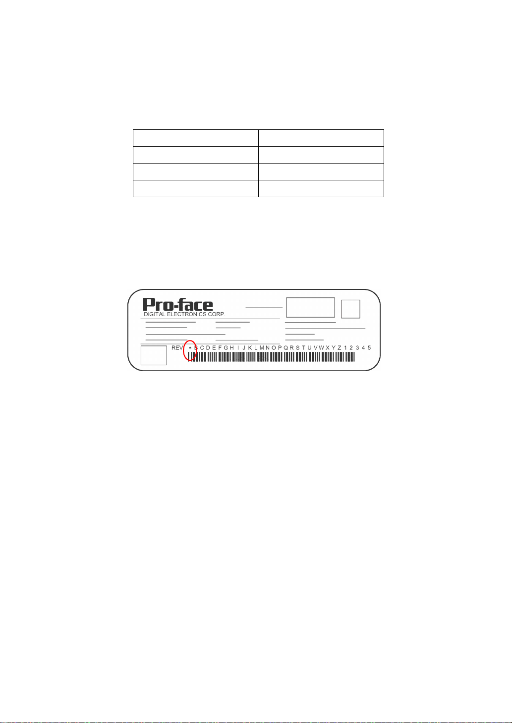
About Revision
The nameplate on the GP has the revision number of the GP . In the example below , the asterisk, which is placed at the “A”
position, shows that the revision number is “A”.
13
Page 15

Contents
Preface ...................................................................................................................... 1
Essential Safety Precautions .................................................................................... 2
About the Manuals.................................................................................................... 8
Information Symbols ................................................................................................. 8
GP-4100 Series Model Name Indication................................................................... 9
GP-4100 Series Model Names ................................................................................. 9
Global Code.............................................................................................................. 9
Package Contents................................................................................................... 10
UL/c-UL Approval.....................................................................................................11
CE Marking ............................................................................................................. 13
About Revision........................................................................................................ 13
Contents.................................................................................................................. 14
Chapter 1 Accessories/System Design
1.1 Accessories ....................................................................................................1-2
1.1.1 Serial Interface Item....................................................................... ... ... ... .... ... ... ....1-2
1.1.2 USB (Type A) Interface.........................................................................................1-2
1.1.3 USB (mini-B) Interface............................................ ... .... ... ... ... .... ..........................1-2
1.1.4 Option Items............................... ....................................... ... ... .... ... ... ....................1-2
1.1.5 Maintenance Items................................................................................................1-3
1.2 System design ................................................................................................ 1-4
1.2.1 GP RUN Mode Peripherals.................................. ... ... .... ... ....................................1-4
1.2.2 Edit Mode Peripherals...........................................................................................1-7
Chapter 2 Part Names and Functions
2.1 GP-4100 Series .............................................................................................. 2-2
Chapter 3 Specifications
3.1 GP-4100 Series .............................................................................................. 3-2
3.1.1 General Specifications............................................................ .... ... ... ... .................3-2
3.1.2 Performance Specifications.......................... .... ... ... ... ....................................... ... .3-4
3.1.3 Serial Interface . ....................................... ... ... .... ... ... ....................................... ... ... .3-7
3.1.4 Dimensions................................... .... ... ... ... ....................................... ... ... .... ... ... ..3-10
Chapter 4 Installation and Wiring
4.1 Installation....................................................................................................... 4-2
14
Page 16

4.2 Wiring Precautions..........................................................................................4-7
4.2.1 Connecting the Power Cord..................................................................................4-7
4.2.2 Connecting the Power Supply ............................................................................4-12
4.2.3 Grounding...........................................................................................................4-13
4.2.4 Wiring Precautions..............................................................................................4-14
4.3 USB Cable Clamp Attachment/Removal ......................................................4-15
4.3.1 USB (Type A) Interface.......................................................................................4-15
4.3.2 USB (mini-B) Interface........................................................................................4-17
Chapter 5 Maintenance
5.1 Cleaning the Display.......................................................................................5-2
5.2 Periodic Check Points.....................................................................................5-3
5.3 Replacing the Installation Gasket ...................................................................5-4
5.4 Replacing the Backlight ..................................................................................5-6
15
Page 17

16
Page 18

1 Accessories/
System Design
1. Accessories
2. System design
1-1
Page 19

GP-4100 Series Hardware Manual
1.1 Accessories
All accessories listed here are produced by Pro-face.
1.1.1
Serial Interface Item
Product Name Model No. Description
Mitsubishi PLC A-Series
Cable (5 m)
Mitsubishi PLC Q-Series
CPU I/F Cable (3 m)
Mitsubishi PLC FX-Series
CPU I/F Cable (1 m)
Mitsubishi PLC FX-Series
CPU I/F Cable (5 m)
Panasonic Electric Works
PLC FP Series CPU Cable
(2 m)
MPICable
ZC9CBA51
ZC9CBQ31
ZC9CBFX1 1
ZC9CBFX51
ZC9CBFP21
CA3-MPI-PGN-PFE
(3.5m)
CA3-MPI-PG1-PFE
(3.5m)
1.1.2 USB (Type A) Interface
Connects the GP directly to the CPU
programming port on the Mitsubishi Electric
PLC A/QnA series. (3.4 inch)
Connects the GP directly to the CPU
programming port on the Mitsubishi Electric
PLC Q series. (3.4 inch)
Connect the GP directly to the CPU
programming port on the Mitsubishi Electric
PLC FX series. (3.4 inch)
Connects the GP directly to the CPU port on
the Panasonic Electric Works PLC FP series.
(3.4 inch)
Connects a host controller to the GP-4107 for
MPI communication.
Product Name Model No. Description
USB Panel-mount Extension
Cable (USB Type A) (1 m)
USB-Serial (RS-232C)
Conversion Cable (0.5 m)
1.1.3 USB (mini-B) Interface
Product Name Model No. Description
USB Transfer Cable
(USB A/mini-B) (1.8 m)
USB Panel-mount Extension
Cable (USB mini-B) (1 m)
1.1.4 Option Items
Product Name Model No. Description
3.4-inch Screen Protection
Sheet
CA5-USBEXT-01
CA6-USB232-01
ZC9USCBMB1
ZC9USEXMB1
ZC9DS31
Extension cable attaching to the USB (Type
A) port on the front side of the operation
panel.
Cable for converting a GP unit’s USB
interface (Type A) into a serial interface (RS232C). Only available for communication
using the Screen Creation Softw a re ’s
Expanded SIO Feature.
Cable for transferring screen data from a PC
(USB A) to the GP (USB mini-B).
Extension cable attaching to the USB (mini-B)
port on the front side of the operation panel.
Disposable, dirt-resistant sheet for the GP
unit’s screen. (5 sheets/set) (Hard type)
1-2
Page 20

1.1.5 Maintenance Items
Product Name Model No. Description
3.4-inch Installation
Fastener
3.4-inch Installation Gasket ZC9WG31
USB Clamp Type A
(1 port)
USB Clamp Type mini-B
(1port)
3.4-inch COM I/F Connector ZC9CMC1
3.4-inch DC Power Supply
Connector
ZC9AF31
ZC9USCL1
ZC9USCLMB1
ZCACNDCS1
Chapter 1 Accessories/System Design
Used to install the GP into a solid panel.
(2 pieces/set)
Provides dust and moisture resistance
when GP is installed into a so li d panel.
(1 gasket)
USB (Type A) Cable clamp for 1 port
products to prevent disconnection.
(5 clamps/set)
USB (mini-B) Cable clamp for 1 port
products to prevent disconnection.
(5 clamps/set)
Connector for Serial I/F
(3.4-inch, 1 connector)
Connector for attaching power supply to
3.4-inch GP units. (Set of 5 connectors)
Limited to models using the DC power
supply connector pictured below.
1-3
Page 21

GP-4100 Series Hardware Manual
1.2
System design
The following diagram illustrates the standard range of items that can be connected to GP-4100 Series units.
For host controller (PLC, etc.) connection information, refer to the “GP-Pro EX Device/PLC Connection
Manual”.
1.2.1 GP RUN Mode Peripherals Serial Communication
GP-4100 Series
For instructions on how to connect to other devices,
always refer to the “GP-Pro EX Device/PLC Connection Manual”.
Serial Interface
(COM1)
Mitsubishi PLC Q Series CPU I/F Cable
ZC9CBQ31
Panasonic Electoric Works PLC FP Series CPU Cable
ZC9CBFP21
RS-232C Cable
(Prepared by user)
Mitsubishi PLC A Series Cable
ZC9CBA51
Mitsubishi PLC FX Series CPU I/F Cable
ZC9CBFX51
ZC9CBFX11
RS-422 Cable
(Prepared by user)
PROFIBUS Cable
(Prepared by user)
MPI Cable
CA3-MPI-PG1-PFE
CA3-MPI-PGN-PFE
RS-232C Port
RS-422/485 Port
RS-485 (isolation) Port
RS-232C type
RS-422/485 type
RS-485 Cable
(Prepared by user)
RS-485(isolation) type
Programming
Console Port
1-4
RS-232C Cable
(Prepared by user)
+
Siemens TTY Converter Cable
CA6-CBLTTY/5M-01
RS-422 Cable
(Prepared by user)
+
Mitsubishi PLC A, QnA, FX Series’s Port Adapter II
GP070-MD11
RS-232C type
Programming
Console Port
RS-422/485 type
Host Controller
PLC etc.
Page 22
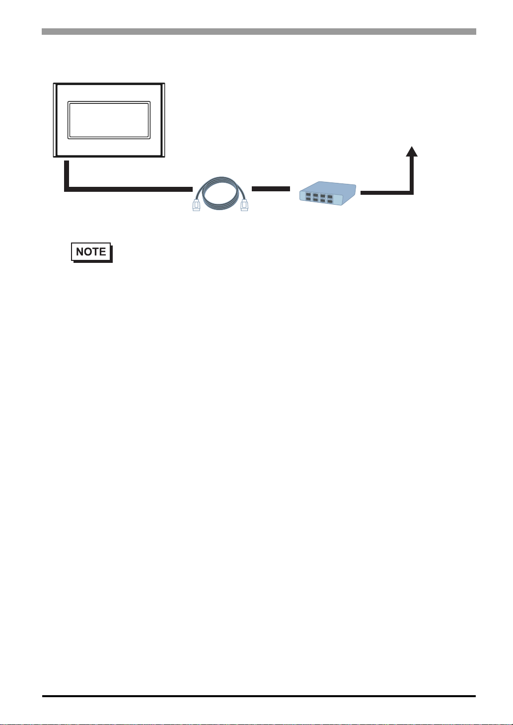
Ethernet communication
GP4104
Ethernet Interface
(10BASE-T/100BASE-TX)
Chapter 1 Accessories/System Design
To an Ethernet Network
Twisted Pair Cable
(commercial type)
• Only GP-4104 supports Ethernet communication.
Hub
(commercial type)
1-5
Page 23
GP-4100 Series Hardware Manual
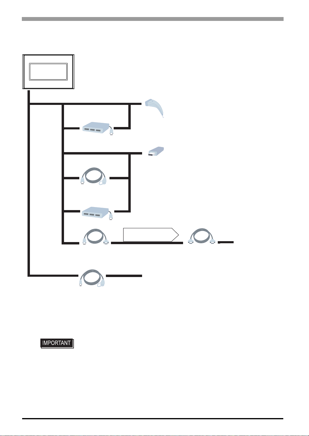
USB (Type A)/ USB (mini-B) Interface
GP-4100 Series
USB (Type A) Interface
(USB1)
Bar-Code Reader
(Commercial type)
USB Hub
(Commercial type)
USB Memory Strage
(Commercial type)
USB Panel-mount
Extension Cable
(USB Type A)
CA5-USBEXT-01
USB Hub
(Commercial type)
USB-Serial (RS-232C)
Conversion Cable
CA6-USB232-01
USB (mini-B) Interface
(USB2)
USB Panel-mount
Extension Cable
(USB mini-B)
*1
For supported models, refer to Pro-face’s support site “Otasuke Pro!”
(http://www.pro-face.com/otasuke/).
You can connect to this site by clicking the GP-Pro EX’s [Help (H)] menu[Connect to Support Site “Otasuke Pro!” (C)] command.
ZC9USEXMB1
Communication using
the Screen Creation Software’s
Extended SIO Feature
*1
*1
RS-232C Cable
(Prepared by user)
Microcomputer Board, etc...
1-6
• If connecting a bar code reader to the GP, be sure to supply power from an external
source (such as a self-powered hub). If you supply power from the GP, the GP may
reset itself because the GP cannot supply enough power.
Page 24
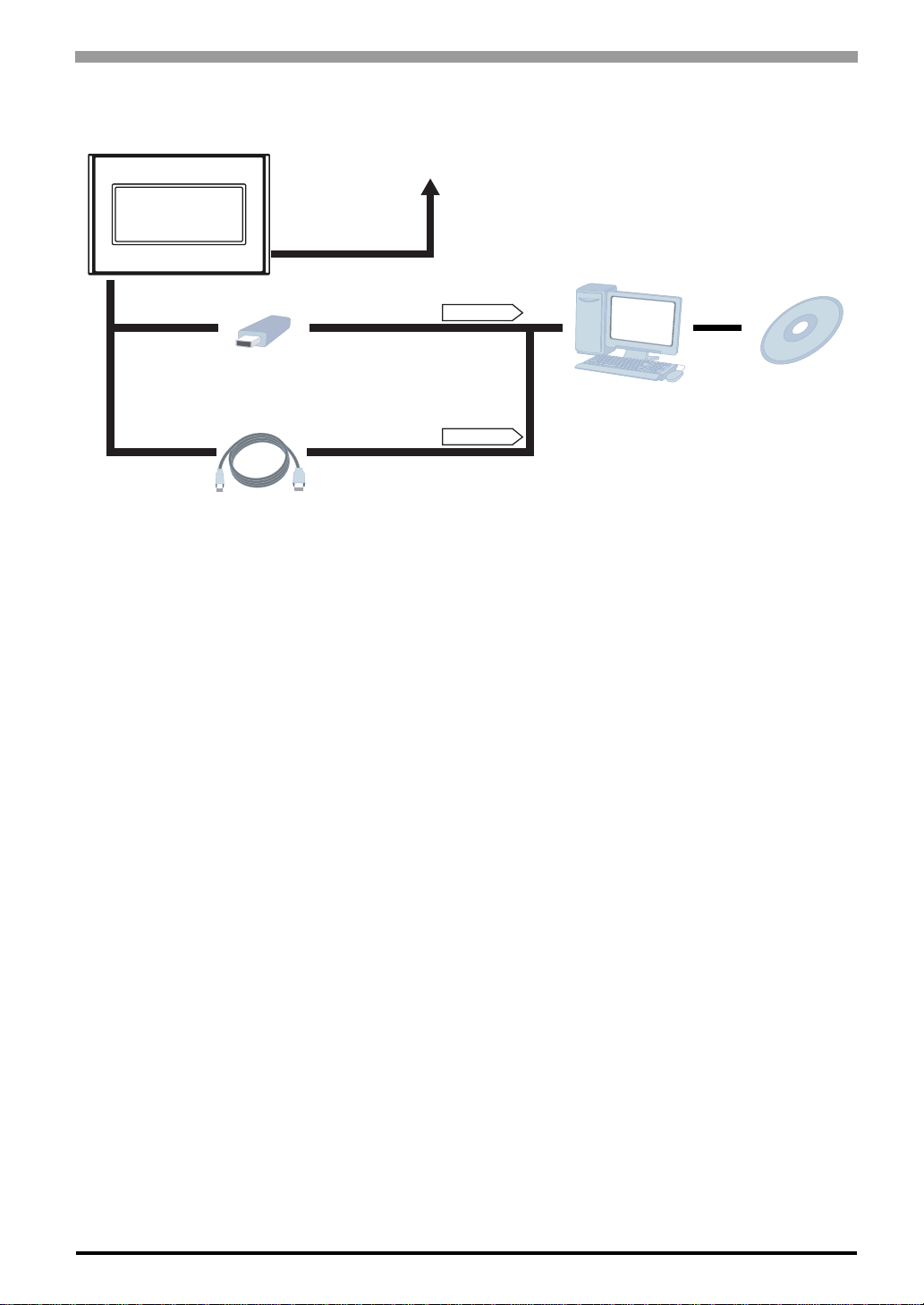
1.2.2 Edit Mode Peripherals
GP-4100 Series
Ethernet Interface
(10BASE-T/100BASE-TX)
Only for GP4104
Chapter 1 Accessories/System Design
To an Ethernet Network
USB (Type A) Interface
(USB1)
USB Memory Strage
(Commercial type)
USB (mini B) Interface
(USB2)
USB Data Transfer Cable
(USB A/mini-B)
ZC9USCBMB1
*1
For supported models, refer to Pro-face’s support site
“Otasuke Pro!” (http://www.pro-face.com/otasuke/).
You can connect to this site by clicking the GP-Pro EX’s [Help (H)] menu[Connect to Support Site“Otasuke Pro!” (C)] command.
*2
Certain types and models of PCs cannot be used.
Please refere to GP-Pro EX Reference Manual
for the software's operating environment requirements.
*1
USB Port
USB Port
Personal Computer
(Commercial type)
*2
Screen Editor
Software
GP-Pro EX
1-7
Page 25

GP-4100 Series Hardware Manual
1-8
Page 26

2 Part Names and
Functions
1. GP-4100 Series
This chapter describes the GP’s part name and functions of each part.
2-1
Page 27
GP-4100 Series Hardware Manual
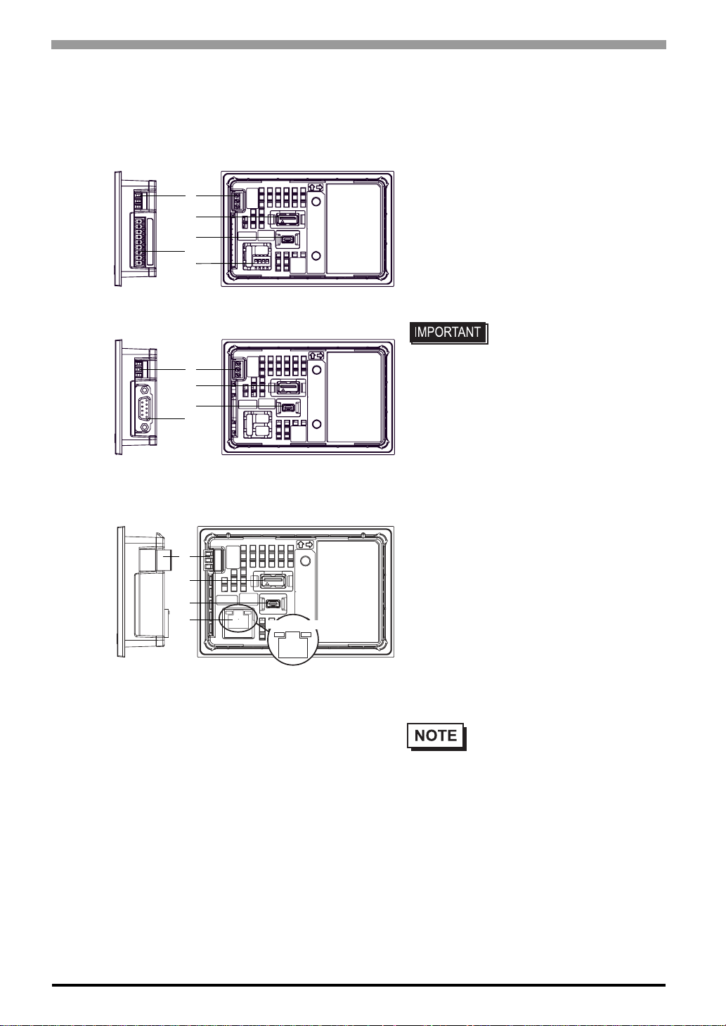
2.1 GP-4100 Series
RS-232C and RS-422/485 Types
(GP-4105, and GP-4106)
A
C
D
B
E
Right side
RS-485 (isolation) Type (GP-4107)
A
C
D
B
Right side Rear
Ethernet Type (GP-4104)
Rear (RS-422/485 Type)
A: Power Connector
B: Serial Interface (COM1)
RS-232C and RS-422/485 Types: 9-pin, 2-piece
terminal block
RS-485(isolation) T ype: D-Sub 9 pin (socket)
C: USB (Type A) Interface (USB1)
Complies with USB 2.0, Uses a “TYPE-A”
connector. Po wer supply voltage: DC5±5%,
The maximum communication distance: 5 m.
• If connecting a bar code
reader to the GP, be sure
to supply power from an
external source (such as a
self-powered hub). If you
supply power from the GP,
the GP may reset itself
because the GP cannot
supply enough power.
A
C
D
F
Right side Rear
ACT LED
D: USB (mini-B) Interface (USB2)
Conforms to USB2.0 (mini-B) x 1
Communication Distance: 5 m or less
LINK LED
E: DIP Switch (SW1)
A terminating resistor can be inserted using the
DIP Switch (4-bit) on the rear of the RS-422/485
type. Factory default settings are all set to “OFF”
(no terminating resistor).
• Check the terminating resistor
required for connection to the
connected device (PLC) and
install if necessary . For detailed
information, refer to the GP-Pro
EX Device/PLC Connection
Manual.
2-2
Page 28
Chapter 2 Part Names and Functions
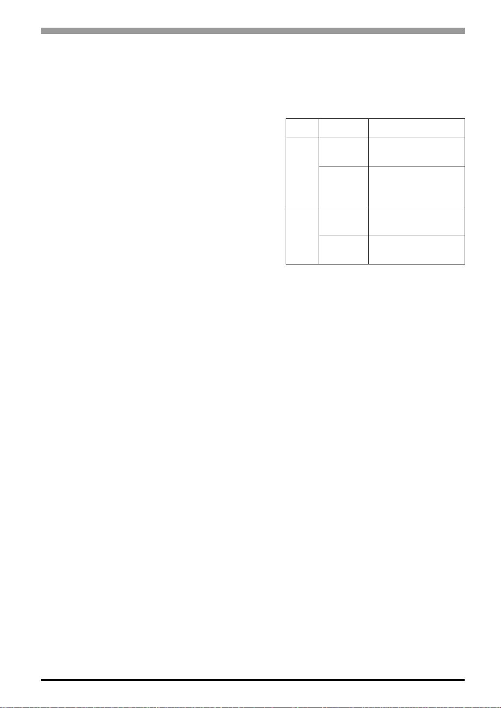
F: Ethernet Interface
The Ethernet transmission interface (10BASE-T/
100BASE-TX). An RJ-45 type modular jack
connector (8-pole) is used. The LED turns on or off
to indicate the current status.
LED Status Indicates
LINK
ACT
Green
ON
Green
OFF
Green
ON
Green
OFF
Data transmission
available
No connection or
subsequent
transmission failure
Data transmission is
occurring.
No data transmission
2-3
Page 29

GP-4100 Series Hardware Manual
2-4
Page 30

3 Specifications
1. GP-4100 Series
This chapter describes the general, functional and interface specifications of the GP as well as its dimensions.
3-1
Page 31
GP-4100 Series Hardware Manual
3.1 GP-4100 Series
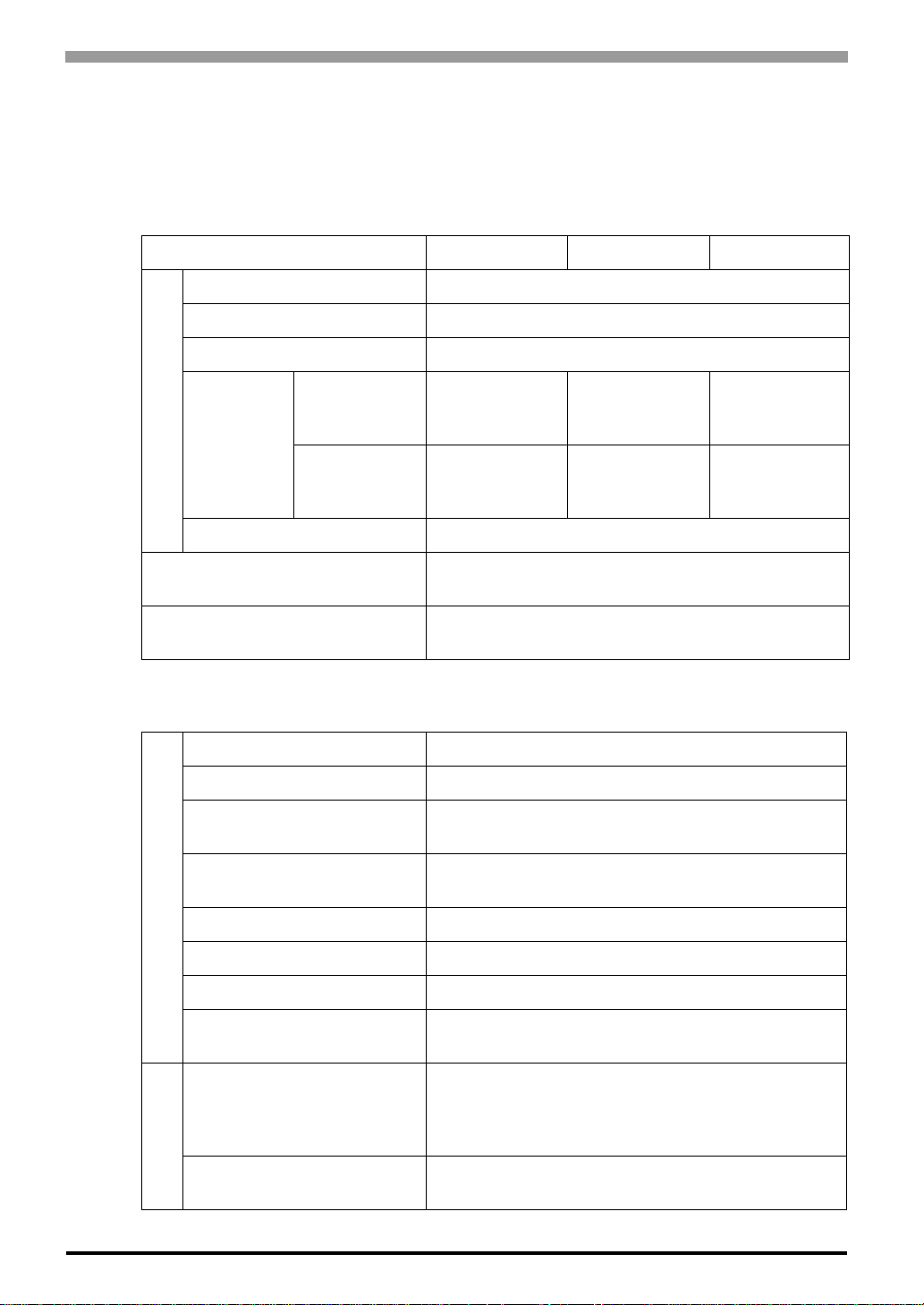
3.1.1 General Specifications Electrical Specifications
Input Voltage DC 24 V
Rated Voltage DC 19.2 to 28.8 V
Allowable Voltage Drop 3 ms or less
When power is
not supplied to
Power
Consumption
Power Supply
In-Rush Current 30 A or less
USB devices
When power is
supplied to
USB devices
GP4104/4105 GP4106 GP4107
2.7 W or less 3.0 W or less 3.4 W or less
6.0 W or less 6.2 W or less 6.5 W or less
Voltage Endurance
Insulation Resistance
Environmental Specifications
Surrounding Air Temperature 0 to 50°C
Storage Temperature -20 to +60°C
Ambient Humidity
Storage Humidity
Physical
Dust 0.1 mg/m
Pollution Degree For use in Pollution Degree 2 environment
Atmosphere Free of corrosive gases
Air Pressure Vibration Resistance
(altitude range)
Vibration Resistance
AC 1,000 V , 20 mA for 1 min (between charging and FG
terminals)
DC 500 V, 10MΩ or more (between charging and FG
terminals)
*1
10 to 90 % RH
(Wet bulb temperature: 39°C or less - no condensation.)
10 to 90 % RH
(Wet bulb temperature: 39°C or less - no condensation.)
3
or less (non-conductive levels)
800 to 1,114 hPa
(2,000 m above sea level or less)
IEC/EN61131-2 compliant
5 to 9 Hz Single amplitude 3.5 mm [0.14 in.]
9 to 150 Hz Fixed acceleration: 9.8 m/s
X, Y, Z directions for 10 cycles (100 min)
2
3-2
Mechanical
Concussion Resistance
IEC/EN61131-2 compliant
147 m/s
2
, X, Y, Z directions for 3 times
Page 32
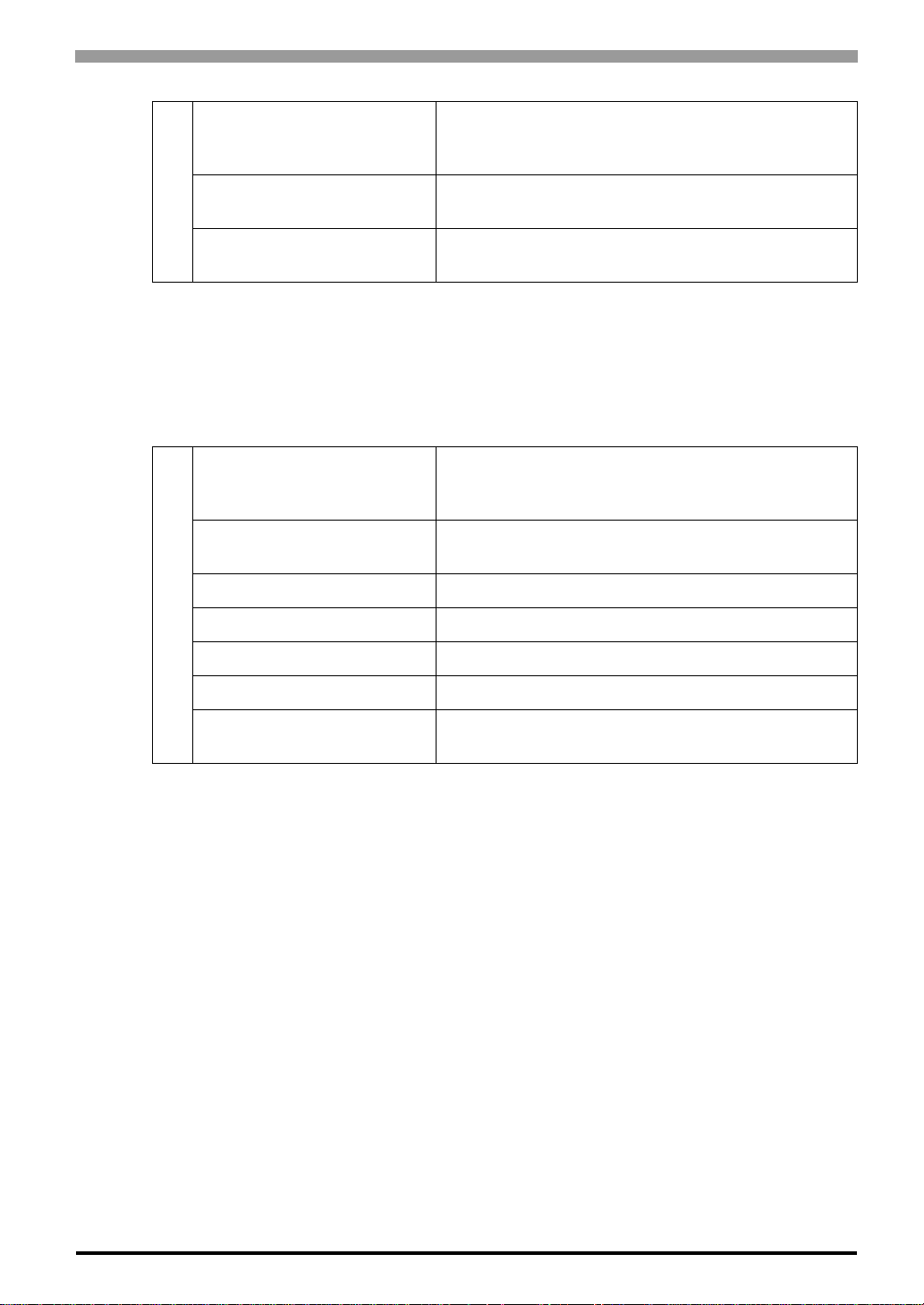
Noise Immunity
Chapter 3 Specifications
Noise Voltage: 1,000 Vp-p
Pulse Duration: 1 µs
Rise Time: 1 ns, (via noise simulator)
Noise Immunity
(Fast Transient Burst Noise)
Electrical
Electrostatic Discharge
Immunity
*1 When using in an environment where the temperature becomes or exceeds 40°C for an
extended period of time, the screen contrast level may decrease from its original level of
brightness.
Structural Specifications
Grounding
Structure
Installation Configuration Embedded panel
Cooling Method Natural air circulation
Installation
Weight Approx. 0.2 kg [0.4 lb] or less (display unit only)
External Dimensions W116.5 x H77.5 x D28 mm [W4.59 x H3.05 x D1.1 in.]
Panel Cut Dimensions
*1
Power Line: 2 kV (IEC/EN61000-4-4)
COM Port (Excluding GP4104): 1 kV (IEC/EN61000-4-4)
Contact Discharge Method: 6 kV/Air Discharge Method: 8 kV
(IEC/EN61000-4-2 Level 3)
Functional grounding:Grounding resistance of 100, 2mm
(14 AWG) or thicker wire, or your country’s applicable
standard.
(Same for FG and SG terminals)
IP65f NEMA #250 TYPE 4X/13
(on the front panel when properly installed in an enclosure)
W105 x H66 mm [W4.13 x H2.6 in.]
Panel thickness area: 1 to 5 mm [0.04 to 0.2 in.]
*2
*3
2
*1 The front face of the GP unit, installed in a solid panel, has been tested using, conditions
equivalent to the standards shown in the specification. Even though the, GP unit’s level of
resistance is equivalent to these standards, oils that should have, no effect on the GP can
possibly harm the unit. This can occur in areas where either, vaporized oils are present, or
where low viscosity cutting oils are allowed to adhere, to the unit for long periods of time. If
the GP’s front face protection sheet becomes, peeled off, these conditions can lead to the
ingress of oil into the GP and separate, protection measures are suggested.
Also, if non-approved oils are present, it may cause deformation or corrosion of the, front
panel’s plastic cover. Therefore, prior to installing the GP be sure to confirm the, type of
conditions that will be present in the GP’s operating environment.
If the installation gasket is used for a long period of time, or if the unit and its gasket, are
removed from the panel, the original level of the protection cannot be guaranteed. To
maintain the original protection level, be sure to replace the installation gasket regularly.
*2 Regarding dimensional tolerance, everything +1/-0 mm [+0.04/-0 in.] and R in angle are
below R3 [R0.12 in.].
*3 Even if panel thickness is within recommend range for “Panel Cut Dimensions”, the panel
could warp, depending on panel’s material, size, and installation location of GP or other
devices. To prevent panel warpage, the installation surface may need to be strengthened.
3-3
Page 33
GP-4100 Series Hardware Manual
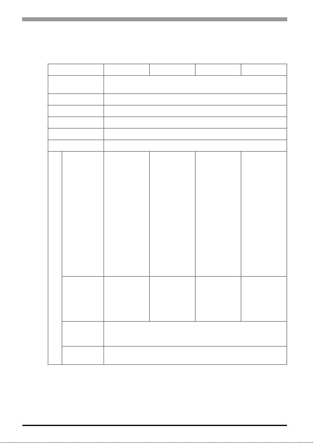
3.1.2 Performance Specifications Performance Specifications
GP4104 GP4105 GP4106 GP4107
Application
Memory
*1
FLASH EPROM 2.2 MB
Logic Program Area None
Font Area None
Data Backup FLASH EPROM 128KB
*2
Variable Area None
Clock Accuracy Uses the clock of an external device
RS-232C
Asynchronous
Transmission
Data Length: 7
or 8 bit
Parity: none,
Odd or Even
Stop Bit: 1 or 2
Serial (COM1)
–
bit
Data
Transmission
Speed: 2,400
bps to 115.2
kbps
Connector: 2piece terminal
Interface
block 9 pin
*3
RS-422/485,
Asynchronous
Transmission
Data Length: 7
or 8 bit
Parity: none,
Odd or Even
Stop Bit: 1 or 2
bit
Data
Transmission
Speed: 2,400
bps to 115.2
kbps
Connector: 2piece terminal
block 9 pin
RS-485
(isolation)
Asynchronous
Transmission
Data Length: 7
or 8 bit
Parity: none,
Odd or Even
Stop Bit: 1 or 2
bit
Data
Transmission
Speed: 2,400
bps to 115.2
kbps, 187.5
kbps (MPI)
Connector: DSub9 (socket)
3-4
IEEE802.3u,
10BASE-T/
Ethernet
100BASE-TX,
Connector:
–––
Modular jack
(RJ-45) x 1
USB
(Type-A)
*4
USB (mini-B)
Conforms to USB2.0 (TYPE-A) x 1
Power Supply Voltage: DC5V ±5%
Communication Distance: 5 m or less
Conforms to USB2.0 (mini-B) x 1
Communication Distance: 5 m or less
*1 Capacity available for user application.
*2 Stores the Alarm History Data, Recipe Data, and Brightness/Contrast Control Settings.
*3 Set up the “Clock Updates“ feature with the Editor software. Please refer to the GP-Pro EX
Reference Manual “Common” - “Clock Update Settings” for details.
*4 If connecting a bar code reader to the GP, be sure to supply power from an external source
(such as a self-powered hub). If you supply power from the GP, the GP may reset itself
because the GP cannot supply enough power.
Page 34
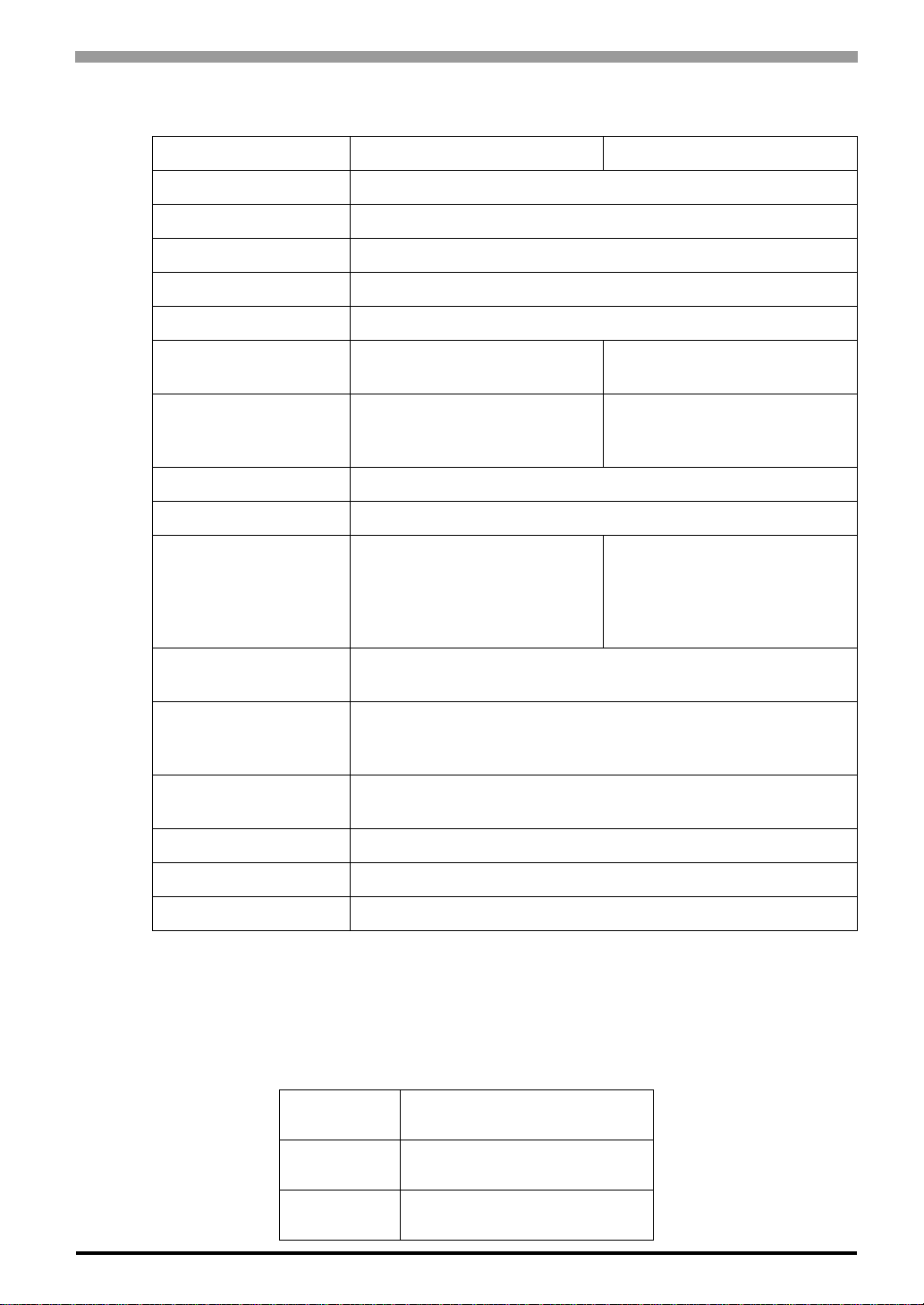
Display Specifications
Chapter 3 Specifications
GP4104G/4105G/4106G/4107G
Display Type STN Monochrome LCD
Display Size 3.4"
Resolution 200 x 80 pixels
Dot pitch W0.4 x H0.4 mm [W0.02 x H0.02 in.]
Effective Display Area 79.985 x 31.985 mm
Display Colors
Backlight
Brightness Control 16 Levels (Adjusted with the touch panel)
Contrast Control 8 Levels (Adjusted with the touch panel)
Backlight Service Life
Language Fonts
*1
*2
Monochrome Green/Red/Orange
(16 Levels)
Green/Red LED
(User nonreplaceable parts.
Factory replacement required.)
Green: 50,000 hrs. or more, Red
10,000 hrs. or more (each in
continuous operation at 25°C
before backlight brightness
decreases to 50%)
Japanese, ASCII, Chinese (Simplified), Chinese (Traditional),
Korean, Cyrillic, Thai
GP4104W/4105W/4106W/4107W
Monochrome White/Red/Pink
(16 Levels)
White/Red LED
(User nonreplaceable parts.
Factory replacement required.)
White: 50,000 hrs. or more, Red
10,000 hrs. or more (each in
continuous operation at 25°C
before backlight brightness
decreases to 50%)
Standard font: 8 x 8, 8 x 16, 16 x 16 and 32 x 32 pixel fonts
Character Sizes
Font Sizes
Text 8 X 16 pixels 25 char. x 5 rows
Text 16 X 16 pixels 12 char. x 5 rows
Text 32 X 32 pixels 6 char. x 2 rows
*1 The backlight burnout detection function is not supported.
*2
Please refer to the GP-Pro EX Reference Manual for details on font types and character codes.
*3 Other font sizes can be set up with the Editor software.
Stroke font: 6 to 80 pixel fonts
Image font: 8 to 72 pixel fonts
Standard font: Width can be expanded up to 8 times. Height can be
expanded up to 8 times.
Touch Panel Specifications
Tou ch Panel
Type
Tou ch Panel
Resolution
Tou ch Panel
Service Life
*3
Resistive Film (analog)
1,024 x 1,024
1,000,000 times or more
3-5
Page 35
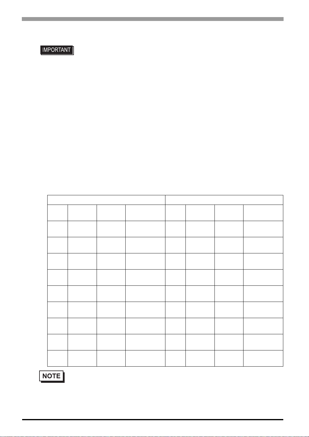
GP-4100 Series Hardware Manual
3.1.3 Serial Interface
• For instructions on how to connect to other devices, always refer to the “GP-Pro EX
Device/PLC Connection Manual”.
• The serial interface of the RS-232C and RS-422/485 types is not isolated. Always
connect the SG (Signal Ground) of the GP unit to the connected device, especially if
the connected device is also not isolated. Failure to do so may damage the RS232C/RS-422/RS-485 circuit.
• An SG (Signal Ground) and FG (Frame Ground) are connected internally in the RS232C and RS-422/485 types. When connecting an external device to the GP using
the SG terminal, be sure to check that no short-circuit loop is created when you
setup the system.
RS-232C and RS-422/485 Types (GP4105/GP4106)
Included COM I/F connector
(9-pin, 2-piece terminal block)
RS-232C type RS-422/485 type
Label
CI CI(RI) Input
CD CD Input Carrier Detect CSA CSA Input
CS CS(CTS) Input
RS RS(RTS) Output
SG SG –
DR DR(DSR) Input
ER ER(DTR) Output
RD RD(RXD) Input Receive Data SDB SDB Output
SD SD(TXD) Output Send Data SDA SDA Output
Signal
Name
Direction Meaning Label
Called status
display
Send
Possible
Request to
Send
Signal
Ground
Data Set
Ready
Data T erminal
Ready
CSB CSB Input
ERB ERB Output
ERA ERA Output
SG SG –
RDB RDB Input
RDA RDA Input
Signal
Name
Direction Meaning
Send
Possible B (-)
Send
Possible A (+)
Data T erminal
Ready B (-)
Data T erminal
Ready A (+)
Signal
Ground
Receive Data
B (-)
Receive Data
A (+)
Send Data B
(-)
Send Data A
(+)
3-6
• A terminating resistor can be inserted using the DIP Switch (4-bit) on the rear of the RS-422/485
type. Factory default settings are all set to “OFF” (no terminating resistor). Check the terminating
resistor required for connection to the connected device (PLC) and install if necessary. For
detailed information, refer to the GP-Pro EX Device/PLC Connection Manual.
Page 36
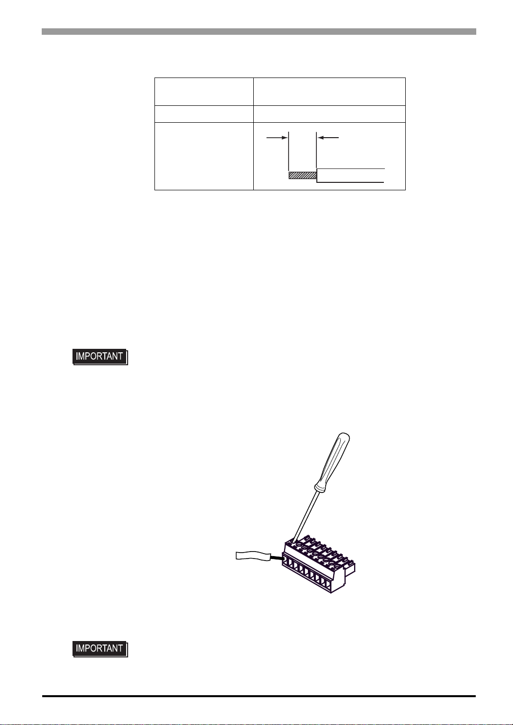
Communications Cable Specifications
Chapter 3 Specifications
Communications
Cable Diameter
Conductor Type Simple or Stranded Wire
Conductor Length
*1 When inserting two wires into one terminal connec-
tor, the simple wire diameter is 0.08 to 0.5mm2 (28 22 AWG), and the stranded wire diameter is 0.08 to
0.75mm
*2 If the Conductor ’s end (individual) wires are not
twisted correctly, the end wires may either short
against each other, or against an electrode.
Wiring the COM Interface Connector
• Always ensure that the connector has been removed from the GP unit before wiring
*1
2
(28 - 20 A WG).
0.14 to 1.5mm
(28 - 16 AWG)
2
*2
7 mm
[0.28 in]
the connector. Failure to do so may result in electric shock.
(1) Remove the COM I/F connector from the GP.
(2) Use a flat-blade screwdriver (Size 0.4 x 2.5) to loosen the terminal screws.
(3) Strip the communications cable, and attach it to the terminal co nnector.
(2)
Use a flat-blade
screwdriver to loosen
the terminal screws.
(4)
Use a flat-blade
screwdriver to tighten
the terminal screws.
(3)
Insert the wire into the
terminal connector.
Terminal Connector
(4) Use a flat-blade screwdriver to tighten the appropriate terminal screws on the terminal connector from
step 3.
• The torque required to tighten these screws is 0.196N•m (1.735[Lb•in]).
(5) Insert the connector into the GP unit’s serial interface.
3-7
Page 37
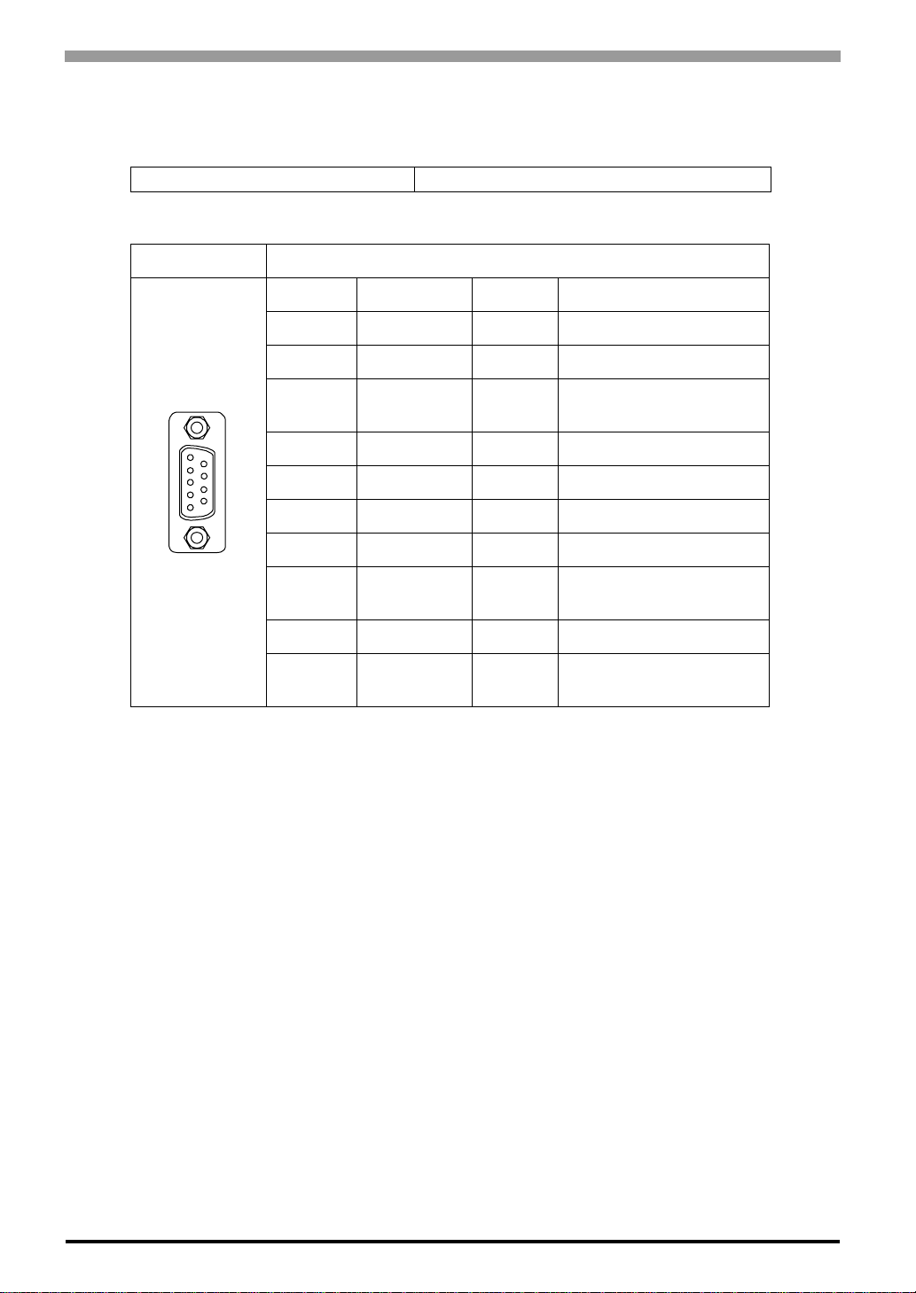
GP-4100 Series Hardware Manual
RS-485 (isolation) type (GP4107)
<GP unit side>
Interfit Bracket #4-40 inch screws are used.
D-Sub 9-pin socket type connector
Pin Connection RS-485 (isolation) type
PIN # Signal Name Direction Meaning
1NC – –
2NC – –
1
5
6
9
(GP unit side)
*1 The SG and FG terminals are isolated.
*2 When providing power of terminating resistor via the Siemens Co.'s PROFIBUS,
*3 The 5V output for Pin # 6 is not protected against overcurrent.
3LINE(+)
Input/
Output
4 RS(RTS) Output Request to Send
5SG
65V
*1
*2 *3
– Signal Ground
– 5V External Output
7NC – –
8 LINE(-)
Input/
Output
9NC – –
Shell FG
*1
–
power cannot be connected to the Device/PLC.
LINE(+)
LINE(-)
Frame Ground
(Common with SG)
3-8
Page 38
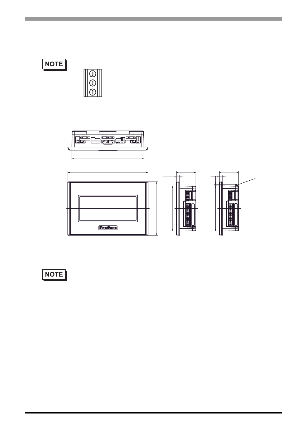
3.1.4 Dimensions External Dimensions (1)
• The dimensions for models with the following type of power connector are shown next.
Unit: mm[in.]
Chapter 3 Specifications
Top
104.5[4.11]
1 16.5[4.59]
Front
• GP unit has two projections*1 on the top to prevent falling during installation. Please insert the
GP unit into the panel at an angle to avoid hitting the projections.
*1 GP units with Rev.1 or higher have projections. More information about revisions, please
read " About Revision " ( page 13).
4.5[0.18]
77.5[3.05]
28[1.10]
65.5[2.58]
4.5
[0.18]
Side
28[1.10]
2.2
[0.09]
65.5[2.58]
projections
(RS-422/485 Type)
3-9
Page 39
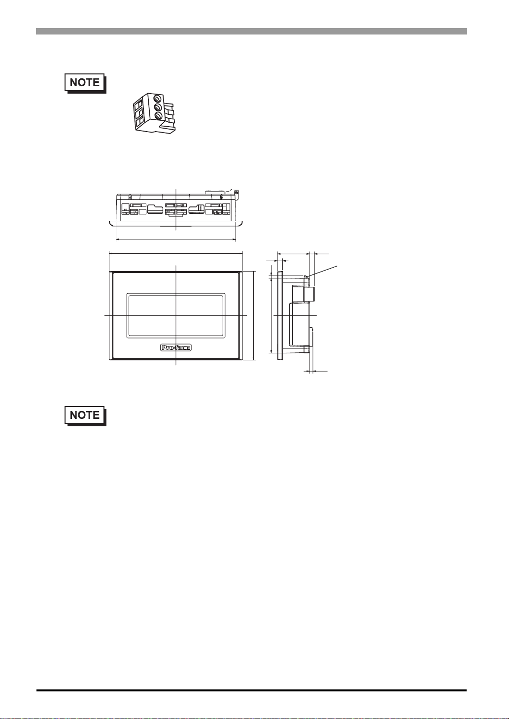
GP-4100 Series Hardware Manual
External Dimensions (2)
• The dimensions for models with the following type of power connector are shown next.
Unit: mm[in.]
Top
104.5[4.11]
116.5[4.59]
77.5[3.05]
Front
• GP unit has two projections*1 on the top to prevent falling during installation. Please insert the
GP unit into the panel at an angle to avoid hitting the projections.
*1 GP units with Rev.1 or higher have projections. More information about revisions, please
read " About Revision " ( page 13).
4.5
[0.18]
2.2
[0.09]
65.5[2.58]
28
[1.10]
Side
4.2
[0.17]
projections
2.9
[0.11]
3-10
Page 40
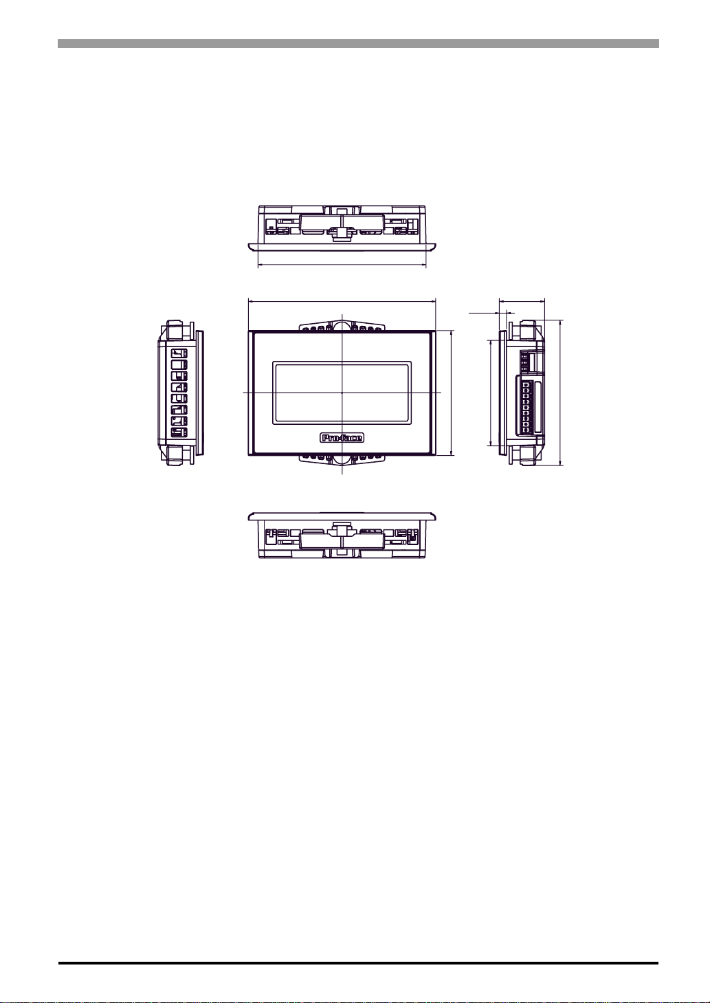
Chapter 3 Specifications
Installation Fasteners Attached Dimensions
The figure shows the RS-422/485 type (GP4106), but all dimensions are common with the GP-4100 Series.
Unit: mm[in.]
Top
104.5[4.11]
Left side
1 16.5[4.59]
Front Right side
Bottom
4.5[0.18]
77.5[3.05]
28[1.10]
65.5[2.58]
(RS-422/485 Type)
90[3.54]
3-11
Page 41
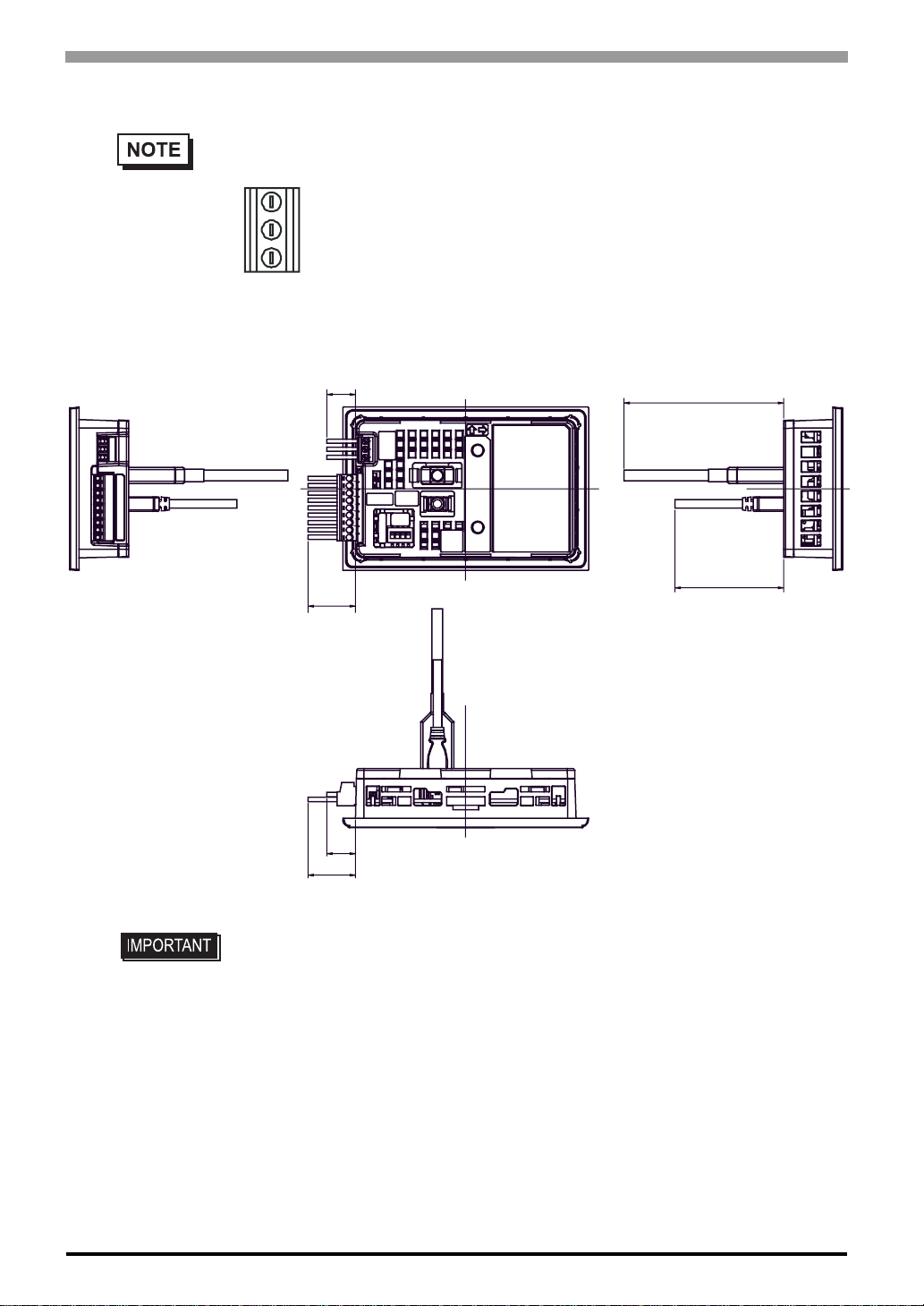
GP-4100 Series Hardware Manual
Cable Attached Dimensions
• For models with the following type of power connector, the dimensions for the RS-232C type
(GP4105) and RS-422/485 type (GP4106) are shown next.
Unit: mm[in.]
Left side
14[0.55]
23
[0.91]
14 [0.55]
23
[0.91]
76[2.99]
51[2.01]
Rear Right side
Bottom
Bottom (RS-422/485 Type)
3-12
• All the above values are designed in case of cable bending. The dimensions given
here are representative values depending on the type of connection cable used.
Therefore, they are all intended for reference only.
Page 42
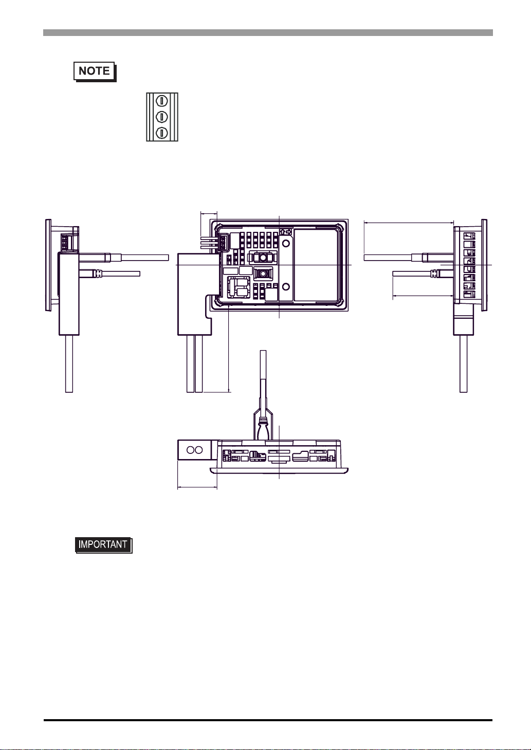
• For models with the following type of power connector, the dimensions for the RS-485
Unit: mm[in.]
Chapter 3 Specifications
(isolation) type (GP4107) are shown next.
14[0.55]
76[2.99]
51[2.01]
Left side
Rear Right side
74[2.91]
33
[1.30]
Bottom
• All the above values are designed in case of cable bending. The dimensions given
here are representative values depending on the type of connection cable used.
Therefore, they are all intended for reference only.
3-13
Page 43
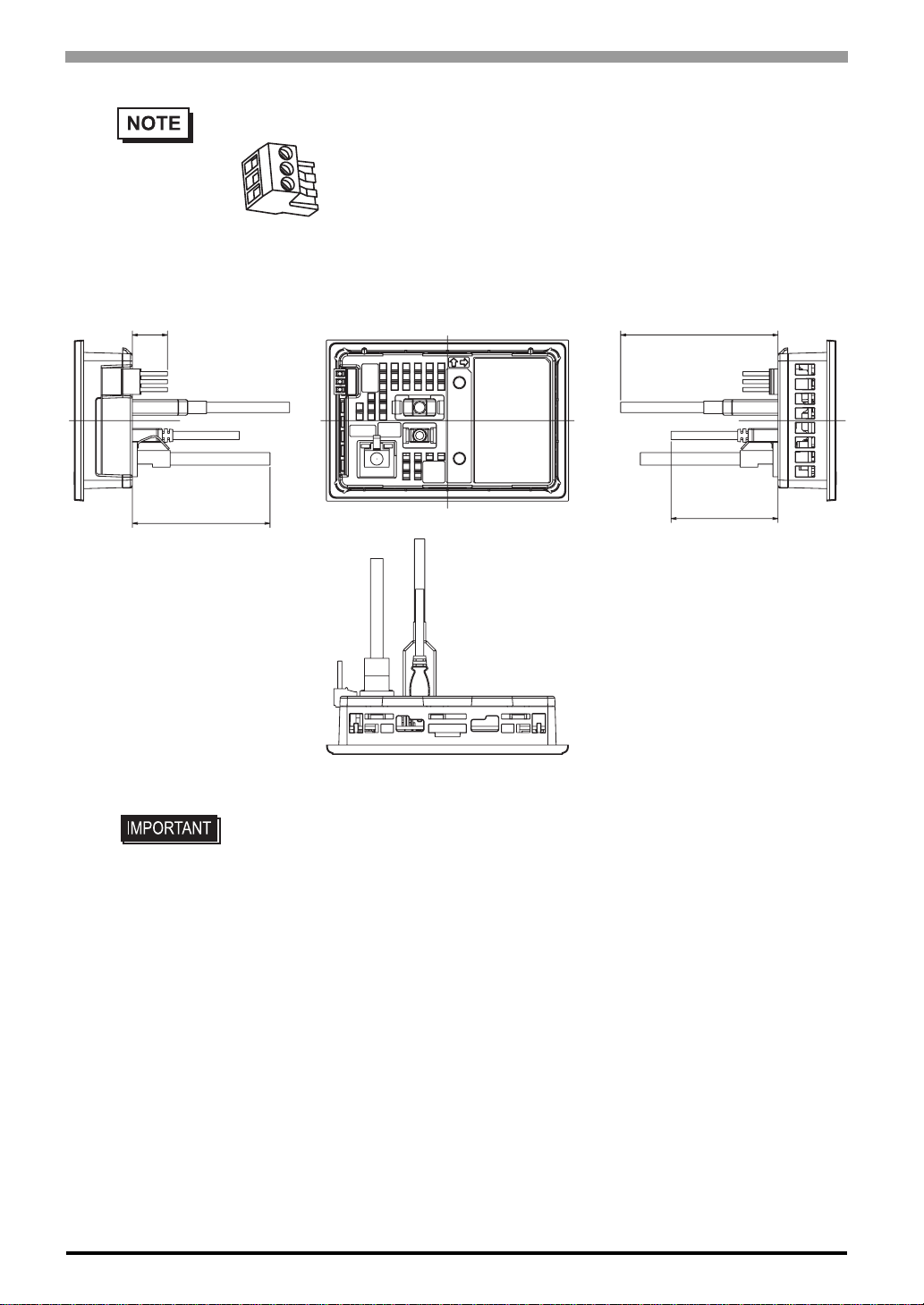
GP-4100 Series Hardware Manual
• The dimensions for models with the following type of power connector are shown next.
Unit: mm[in.]
17
[0.67]
76[2.99]
66[2.60]
Left side
Rear
51[2.01]
Right side
Bottom
• All the above values are designed in case of cable bending. The dimensions given
here are representative values depending on the type of connection cable used.
Therefore, they are all intended for reference only.
3-14
Page 44
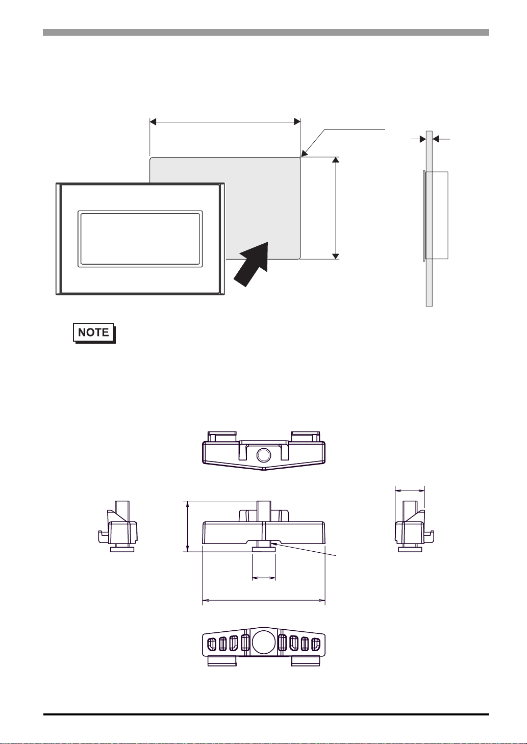
Panel Cut Dimensions
Unit: mm[in.]
105.0
+1
[4.13 ]
-0
+0.04
-0
r ≤ 3 [0.12]
-0
+0.04
[2.60 ]
-0
+1
66.0
Chapter 3 Specifications
Panel thickness area
1.0[0.04] to 5.0[0.20]
• Please read “4.1 Installation” before designing the Panel Cut.
Installation Fasteners
Unit: mm[in.]
12.8[0.50]
22[0.87]
M6
Φ10
[0.39]
53[2.09]
3-15
Page 45

GP-4100 Series Hardware Manual
3-16
Page 46

4 Installation and
Wiring
1. Installation
2. Wiring Precautions
3. USB Cable Clamp Attachment/Removal
4-1
Page 47
GP-4100 Series Hardware Manual
4.1 Installation
This section describes the procedures and precautions for installing the GP Series units.
Check the Installation Gasket’s Seating
It is strongly recommended that you use the installation gasket, since it absorbs vibration in addition to
repelling water.
For the procedure for attaching the installation gasket, refer to "5.3
SEE
5.3 Replacing the Installation Gasket (page 5-4)
• Before installing the GP into a cabinet or panel, check that the installation gasket is
securely attached to the unit.
• A gasket which has been used for a long period of time may have scratches or dirt on
it, and could have lost much of its dust and drip resistance. Be sure to change the
gasket periodically (or when scratches or dirt become visible).
Replacing the Installation Gasket".
Creating a Panel Cut
Create the correct sized opening required to install the GP, using the installation dimensions given.
Decide the panel’s thickness based on the level of panel strength required.
SEE
Panel Cut Dimensions (page 3-15)
• Check that the installation panel or cabinet’s surface is flat, in good condition and has no jagged
edges.
• Even if panel thickness is within recommend range for “Panel Cut Dimensions”, the panel could
warp, depending on panel’s material, size, and installation location of GP or other devices. To
4-2
prevent panel warpage, the installation surface may need to be strengthened.
Page 48
Chapter 4 Installation and Wiring
Installation Requirements
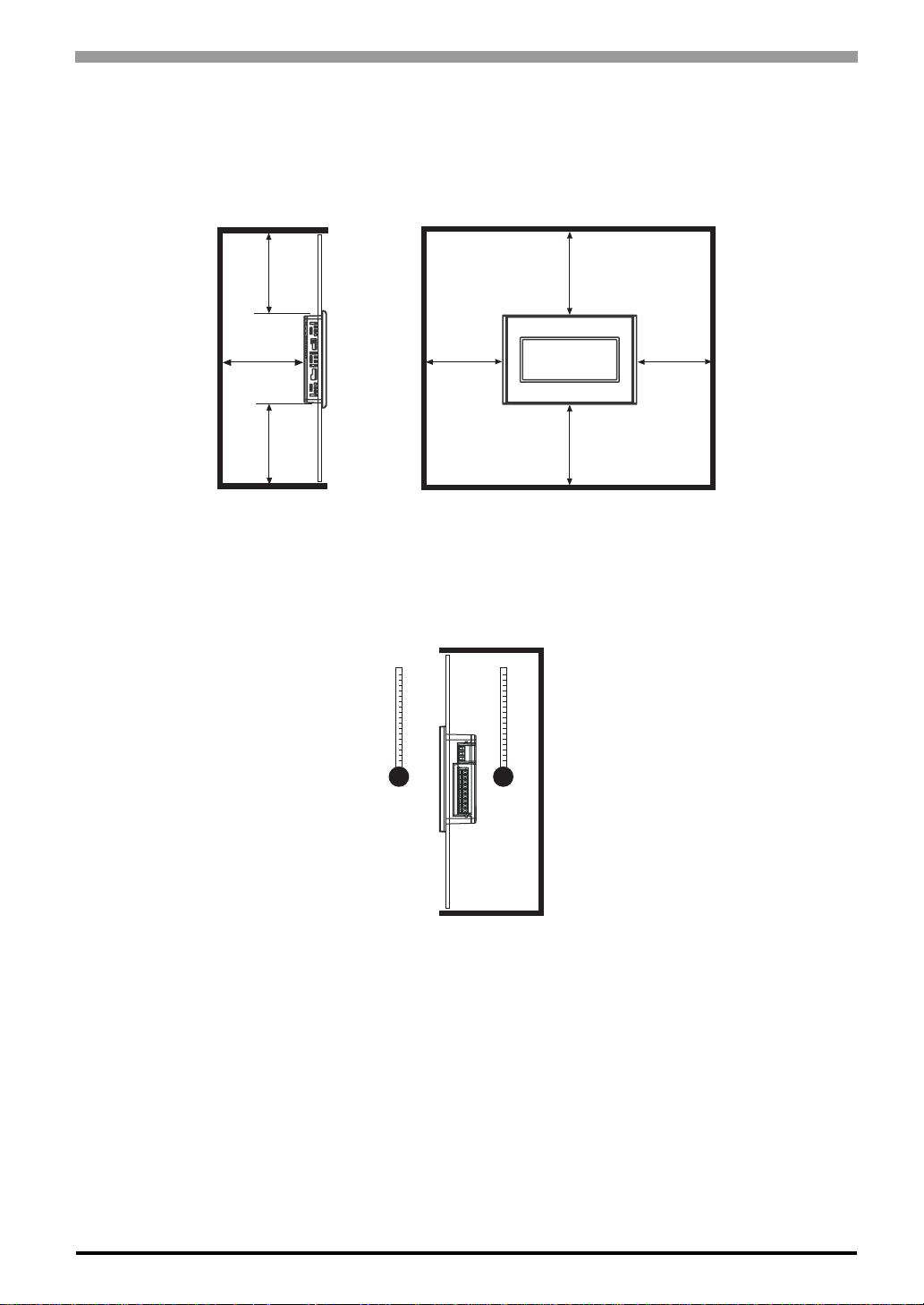
• For easier maintenance, operation, and improved ventilation, be sure to install the GP at least 100 mm
[3.94 in.] away from adjacent structures and otherequipment.
Unit: mm[in.]
100
[3.94]
100[3.94]
100
[3.94]
• Be sure that the surroundin g air temperature an d the ambient humidity are within their designated ranges.
(Surrounding air temperature: 0 to 50°C, Ambient humidity: 10 to 90%RH, Wet bulb temperature: 39°C
max.) When installing the GP on the panel of a cabinet or enclosure, "Surrounding air temperature"
indicates both the panel face and cabinet or enclosure’s internal temperature.
100[3.94]
100[3.94]
100[3.94]
100[3.94]
Panel
Face
• Be su re that heat from surrounding equipment does not cause the GP to exceed its standard operating
temperature.
Cabinet
interior
4-3
Page 49
GP-4100 Series Hardware Manual
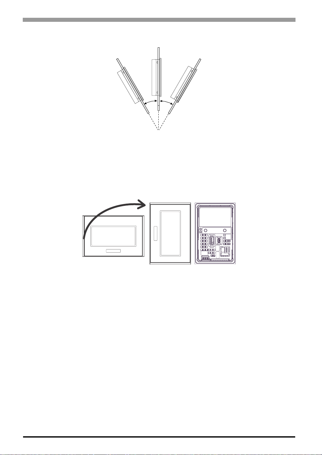
• When installing the GP in a slanted panel, the panel face should not incline more than 30°.
• When installing the GP in a slanted panel, and the panel face inclines more than 30°, the ambient
temperature must not exceed 40°C. You may need to use forced air cooling (fan, A/C) to ensure the
ambient operating temperature is 40°C or below.
• When mo unting the GP unit vertically, ensure that the left side of the unit faces up (i.e. the power
connector and serial interface should be at the bottom).
30° or less
Mounted
Horizontally
(RS-422/485 Type)
Front and Rear Views
when Mounted Vertically
4-4
Page 50
Chapter 4 Installation and Wiring
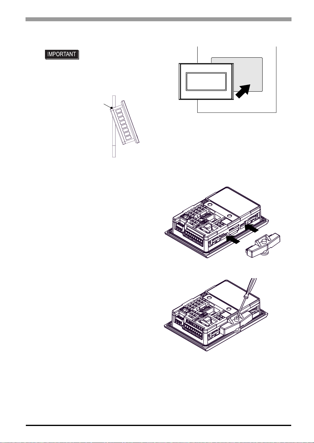
Installing the GP
(1) Insert the GP into the panel cut, as shown.
• GP unit has two projections*1
on the top to prevent falling
during installation. Please
insert the GP unit into the
panel at an angle to avoid
hitting the projections.
projections
Insert GP at
an angle.
*1 GP units with Rev.1 or higher have projections. More information about revisions, please read "About
Revision" ( page 13 ).
(2) Insert th e installation fastener hooks to the
insertion slots on the GP unit.
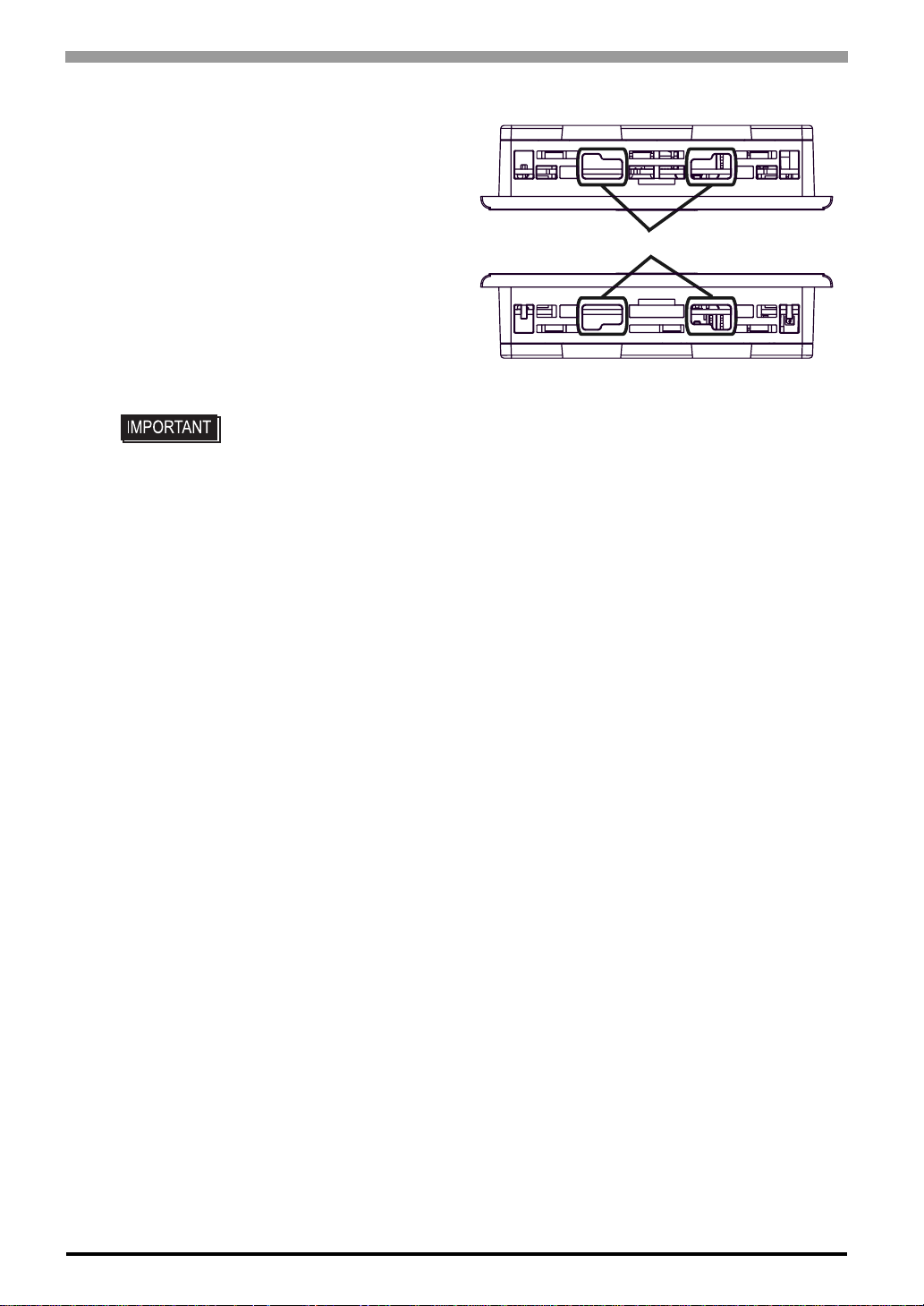
(3) Tighten the installation fasteners with a
screwdriver. There are two insertion slots
on both the top and bottom of the GP unit.
(2)
Insert the hooks to the
insertion slots.
(3)
Tighten the screw
with a screwdriver
4-5
Page 51
GP-4100 Series Hardware Manual
• Tightening the screws with too much force can damage the GP unit’s plastic case.
• In order to guarantee water repelling effect the necessary torque is 0.52N•m
[4.60Lb•in].
Top
Insertion Slots
Bottom
4-6
Page 52
4.2 Wiring Precautions
This section describes the procedures and precautions for wiring power cords.
4.2.1 Connecting the Power Cord
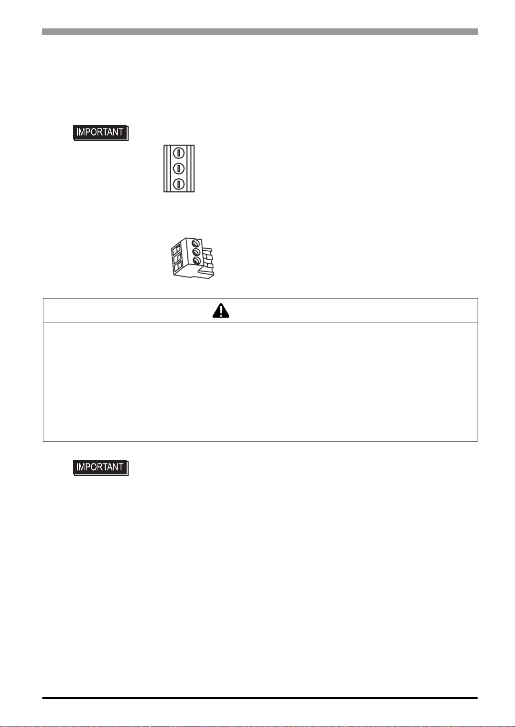
• If the power connector is the following type, please read the following.
• If the power connector is the following type, please read from page 4-11.
Chapter 4 Installation and Wiring
WARNING
HAZARD OF ELECTRIC SHOCK
• Prior to connecting the GP unit's power cord terminals to the power terminal block, confirm that the GP
unit's power supply is completely turned OFF, via a breaker, or similar unit.
• Supplying a power voltage other than that specified will damage the power source and the GP unit.
• Since there is no power switch on the GP unit, be sure to attach a breaker-type switch to its power cord.
• When the FG terminal is connected, be sure the wire is grounded.
Failure to follow these instructions will result in death or serious injury.
• When the FG terminal is connected, be sure the wire is grounded. Not grounding the
GP unit will result in excess noise and vibration.
• The SG and FG terminals are connected internally in the GP unit.
When connecting the SG wire to another device, be sure that the design of the
system/connection does not produce a shorting loop.
4-7
Page 53
GP-4100 Series Hardware Manual
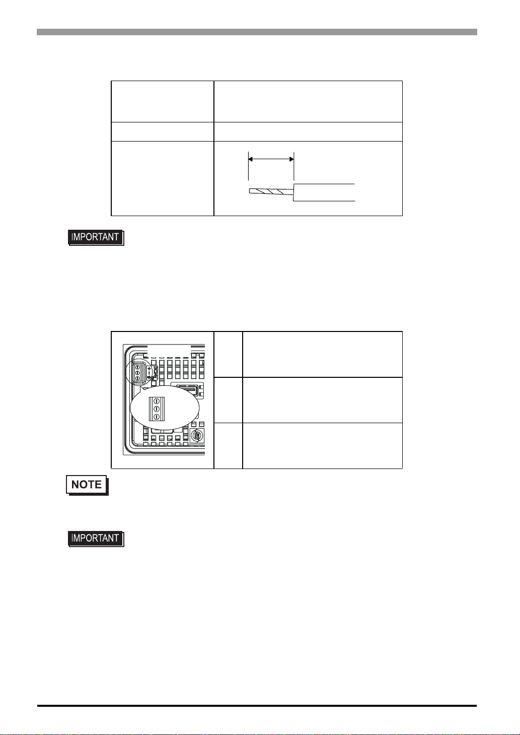
Power Cord Specifications
Simple Wire: 0.75 to 1.5mm
Power Cord Diameter
Conductor Type Simple or Twisted Wire
Conductor Length
• Use copper conductors only.
• If the Conductor’s end (individual) wires are not twisted correctly, the end wires may
either short against each other, or against an electrode.
Stranded Wire: 0.75 to 1mm
(18 - 16 AWG)
Power Connector Specifications
GP Rear
2
2
5mm
[0.2 in.]
24V
+
0V
+
-
FG
• The power supply connector is MKDS 1/3-3,81 (made by Phoenix Contact).
-
FG Grounding T erminal connected to
FG
the GP
Connecting the Power Cord
• To avoid an electric shock, prior to connecting the GP unit’s power cord terminals to
the power terminal block, confirm that the GP unit's power supply is completely
turned OFF, via a breaker, or similar unit.
• The temperature rating of field installed Conductors:75°C only.
(1) Confirm that the GP unit’s Power Cord is unplugged from the power supply.
(2) Use a flat-blade screwdriver (Size 0.4 x 2.5) to loosen the terminal screws.
(3) Strip the power cord, and attach it to the power connector.
4-8
Page 54
Chapter 4 Installation and Wiring
(4) Use a flat-blade screwdriver to tighten the appropriate terminal screws on the terminal connec-
tor from step 3.
• Use a flat-blade screwdriver (Size 0.4 x 2.5) to tighten the terminal screws.
The torque required to tighten these screws is 0.28N•m
• The power connector cannot be removed because it is mounted to GP unit. Do not
attempt to remove or tamper with the power connector. It may damage the power
connector.
• Be sure to loosen the terminal screws before pulling out the power cord. The power
connector may be damaged by pulling the power cord when attached to the power
connector.
• Do not solder the cable connection. Doing so may damage the unit due to abnormal
heat or cause a fire.
• Be sure to twist the power cords together, up to the power connector.
(2.5 [Lb•in])
.
4-9
Page 55
GP-4100 Series Hardware Manual
WARNING
HAZARD OF ELECTRIC SHOCK
• Prior to connecting the GP unit's power cord terminals to the power terminal block, confirm that the GP
unit's power supply is completely turned OFF, via a breaker, or similar unit.
• Supplying a power voltage other than that specified will damage the power source and the GP unit.
• Since there is no power switch on the GP unit, be sure to attach a breaker-type switch to its power cord.
• When the FG terminal is connected, be sure the wire is grounded.
Failure to follow these instructions will result in death or serious injury.
• When the FG terminal is connected, be sure the wire is grounded. Not grounding the
GP unit will result in excess noise and vibration.
• The SG and FG terminals are connected internally in the GP unit.
When connecting the SG wire to another device, be sure that the design of the
system/connection does not produce a shorting loop.
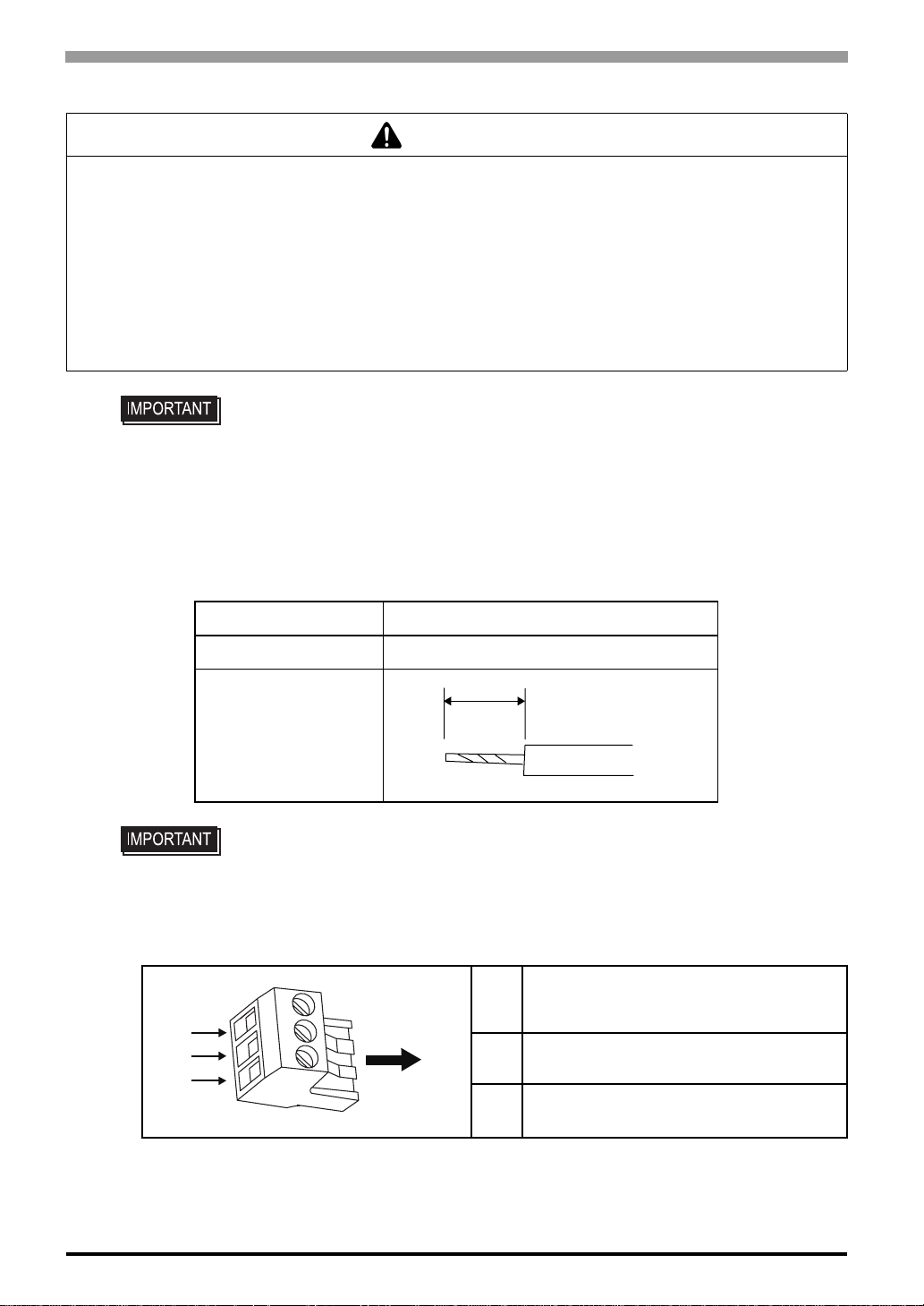
Power Cord Specifications
Power Cord Diameter 0.75 to 1.5mm
Conductor Type Simple or Twisted Wire
Conductor Length
• Use copper conductors only.
• If the Conductor’s end (individual) wires are not twisted correctly, the end wires may
either short against each other, or against an electrode.
Power Connector (Plug) Specifications
Insertion
+
Direction
-
FG
2
(18-16AWG)
7mm
[0.3in.]
24V
+
0V
-
FG Grounding Terminal connected to the
FG
GP
4-10
Page 56
Chapter 4 Installation and Wiring
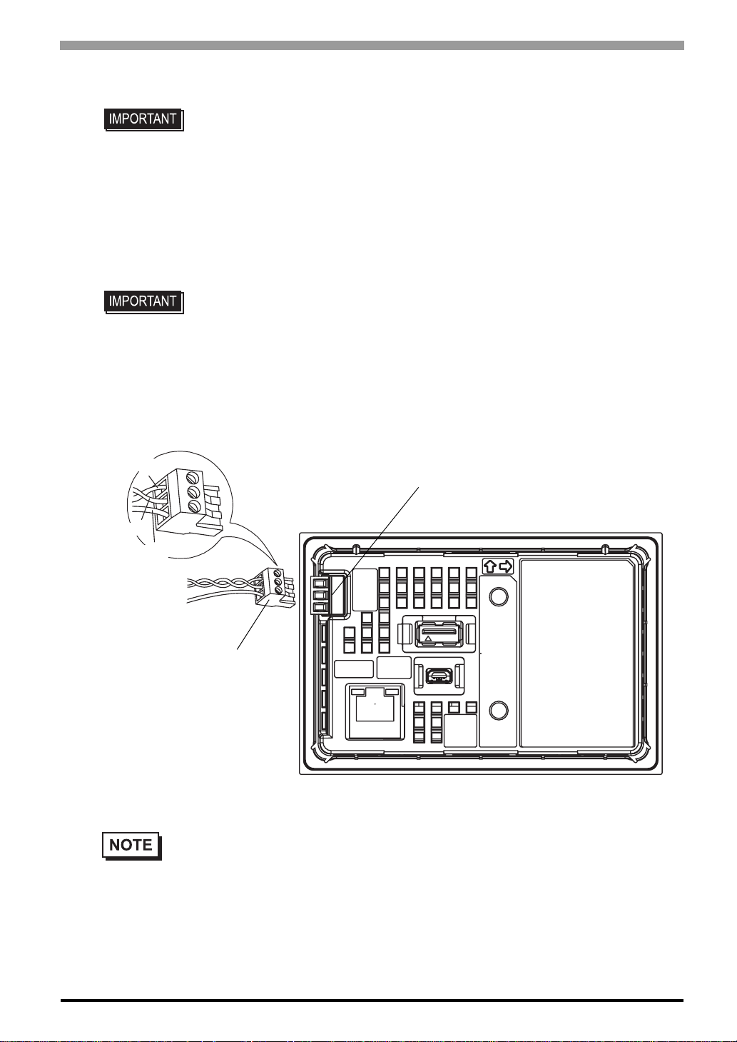
Connecting the Power Cord
• Be sure to remove the connector from the GP unit prior to starting wiring. Failure to
do so may cause an electric shock.
o
• The temperature rating of field installed Conductors:75
(1) Confirm that the power cord is unplugged from the power supply.
(2) Check the rated voltage, and remove the sticker on the power connector that reads "DC 24V".
(3) Remove the power connector (plug) from the main unit.
(4) Strip the membrane of the power cord, and connect them to the Power Connector.
• Use a flat-blade screwdriver (Size 0.4 x 2.5 mm (0.015 to 0.098 in.)) to tighten the
terminal screws.
The torque required to tighten these screws is 0.22 to 0.25N•m[1.95 to 2.2Lb•In.].
• Do not solder the cable connection. Doing so may damage the unit due to abnormal
heat or cause a fire.
(5) Reattach the Power Connector (plug).
Power
+
Connector
(Socket)
C only.
−
FG
Power Connector (Plug)
• Be sure to twist the power cords together, up to the power connector.
Rear
(GP4104)
4-11
Page 57
GP-4100 Series Hardware Manual
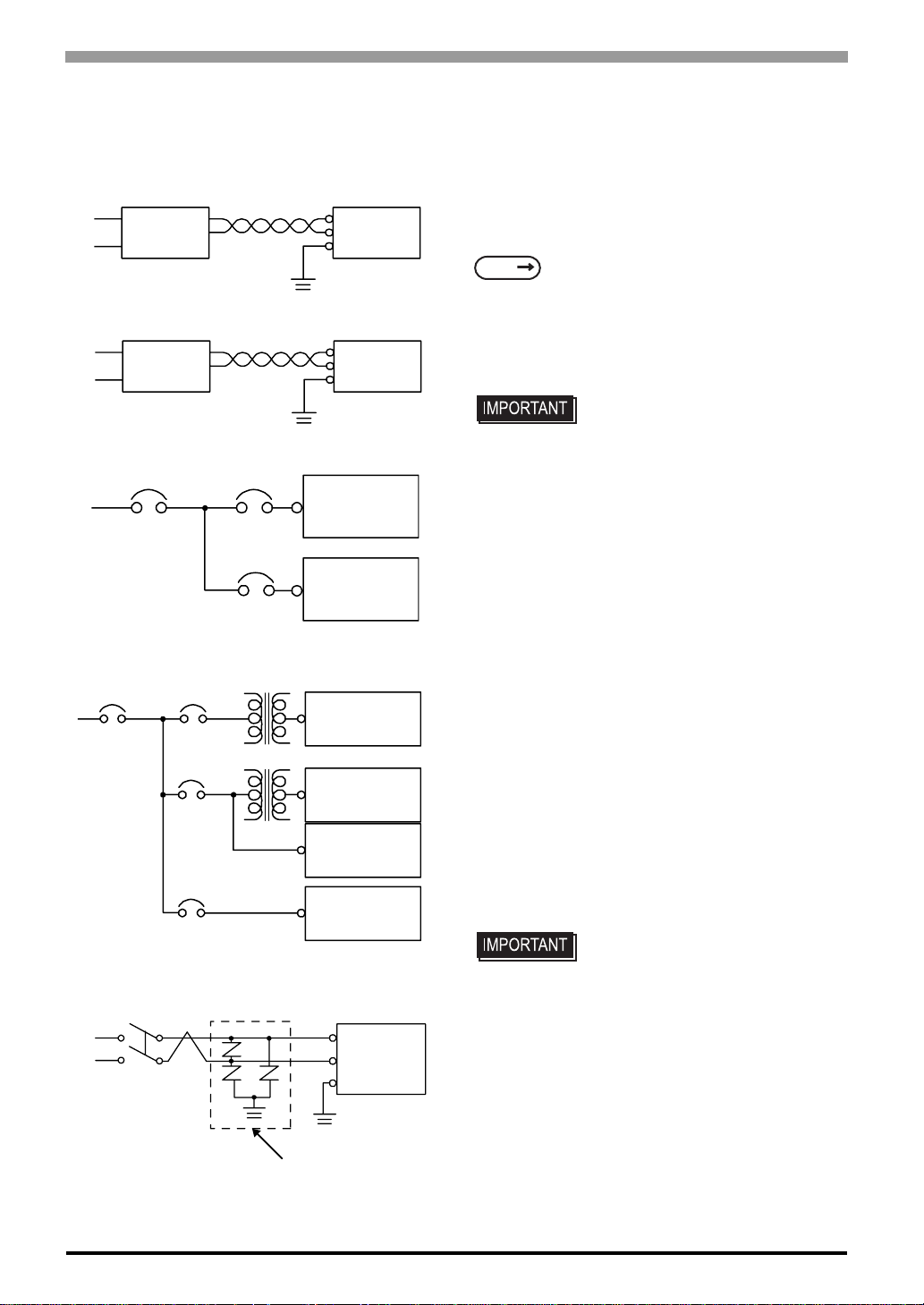
4.2.2 Connecting the Power Supply
This section describes the precautions for supplying a power voltage.
Constant
Voltage
Transformer
nsulating
I
Transformer
Main Power
Main
Power
Twisted-pair cord
Twisted-pair cord
GP Power
Input/Output
Power
GP
Power
T1
T2
Input/
Output
Power
Main Circuit
GP
FG
GP
FG
GP
Input/Output
Unit
GP
Input/Output
Unit
Input/Output
Unit
Operation
Unit
• If the supplied voltage exceeds the GP unit’s range,
connect a constant voltage transformer.
SEE
Chapter 3 Specifications (page 3-1)
• For between the line and ground, select a power
supply that is low in noise. If there is an excess amount
of noise, connect a insulating transformer.
• Use constant voltage and
insulating transformers with
capacities exceeding Power
Consumption value.
• When supplying power to the GP unit, be sure to
separate the input/output and power lines, as shown.
• To increase the noise resistance quality of the power
cord, simply twist each power wire before attaching the
Ring Ter minal.
• The power supply cable must not be bundled or
positioned close to main circuit lines (high voltage, high
current), or input/output signal lines.
• Connect a lightening surge absorber, as sho wn in th e
diagram, to deal with power surges.
• To avoid excess noise, make the power cord as short as
possible.
• Be sure to ground the surge
4-12
E1
Lightening Surge
Absorber
FG
E2
GP
absorber (E1) separately from the
GP unit (E2).
• Select a surge absorber that has
a maximum circuit voltage greater
than that of the peak voltage of
the power supply.
Page 58
Chapter 4 Installation and Wiring
4.2.3 Grounding
This section describes the precautions for grounding the GP unit.
CAUTION
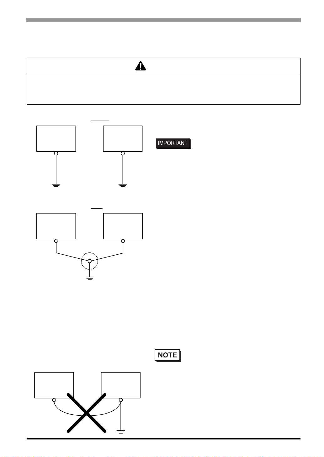
UNINTENDED EQUIPMENT OPERATION AND DAMAGE
• Do not use common grounding, since it can lead to an accident or machine breakdown.
Failure to follow the instruction will result in equipment damage.
(a) Exclusive Grounding (BEST)
GP
(b) Exclusive Grounding (OK)
GP
Other
Equipment
Other
Equipment
• When supplying power to the GP unit, be sure to separate the
input/output and power lines, as shown. [diagram (a)]
• Check that the grounding resistance is
100Ω or less.
• FG and SG terminals are internally
connected in the GP. When connecting
an external device to the GP using the
SG terminal, be sure to check that no
short-circuit loop is created when you
setup the system.
• The grounding wire should have a cross
sectional area greater than 2mm
AWG) Create the grounding point as
close to the GP unit as possible, and
make the wire as short, as possible.
When using a long grounding wire,
replace the thin wire with a thicker wire,
and place it in a duct.
2
(14
(C) Common Grounding (Not OK)
GP
Other
Equipment
• If exclusive grounding is not possible, use a common grounding
point. [diagram (b)] A D-type grounding or equivalent should
be used for the grounding point.
• If the equipment does not function properly
when grounded, disconnect the ground wire
from the FG terminal.
4-13
Page 59
GP-4100 Series Hardware Manual
4.2.4 Wiring Precautions
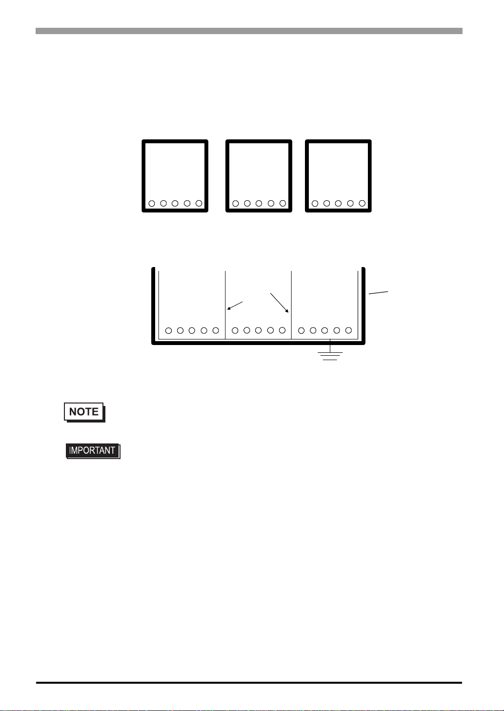
To help prevent noise and interference problems, separate all con trol, communication and power lines by
placing them in a separate ducts.
Duct for I/O Signal
Lines
If different wires must be placed in the same duct, separate them with an earthed/grounded divider.
I/O Signal Lines Control Lines Power Lines
Duct for Control
Lines
Grounded
Separators
Duct for Power
Lines
Duct
(non-conducting
resin/plastic)
Earth/Ground
4-14
• If the lines cannot be separated, use shielded lines and create a ground from the shield line.
• Use noise-reducing external wiring methods to increase overall system reliability.
• To prevent po wer surges or noise interference, use ducts to separate all DC I/O
or current circuit wires from communication cables.
• To prevent malfun ctions due to noise, communication cables must be wired
separately from high-frequency lines and power lines such as high-voltage lines,
high-current lines, and inverters.
Page 60
4.3 USB Cable Clamp Attachment/Removal
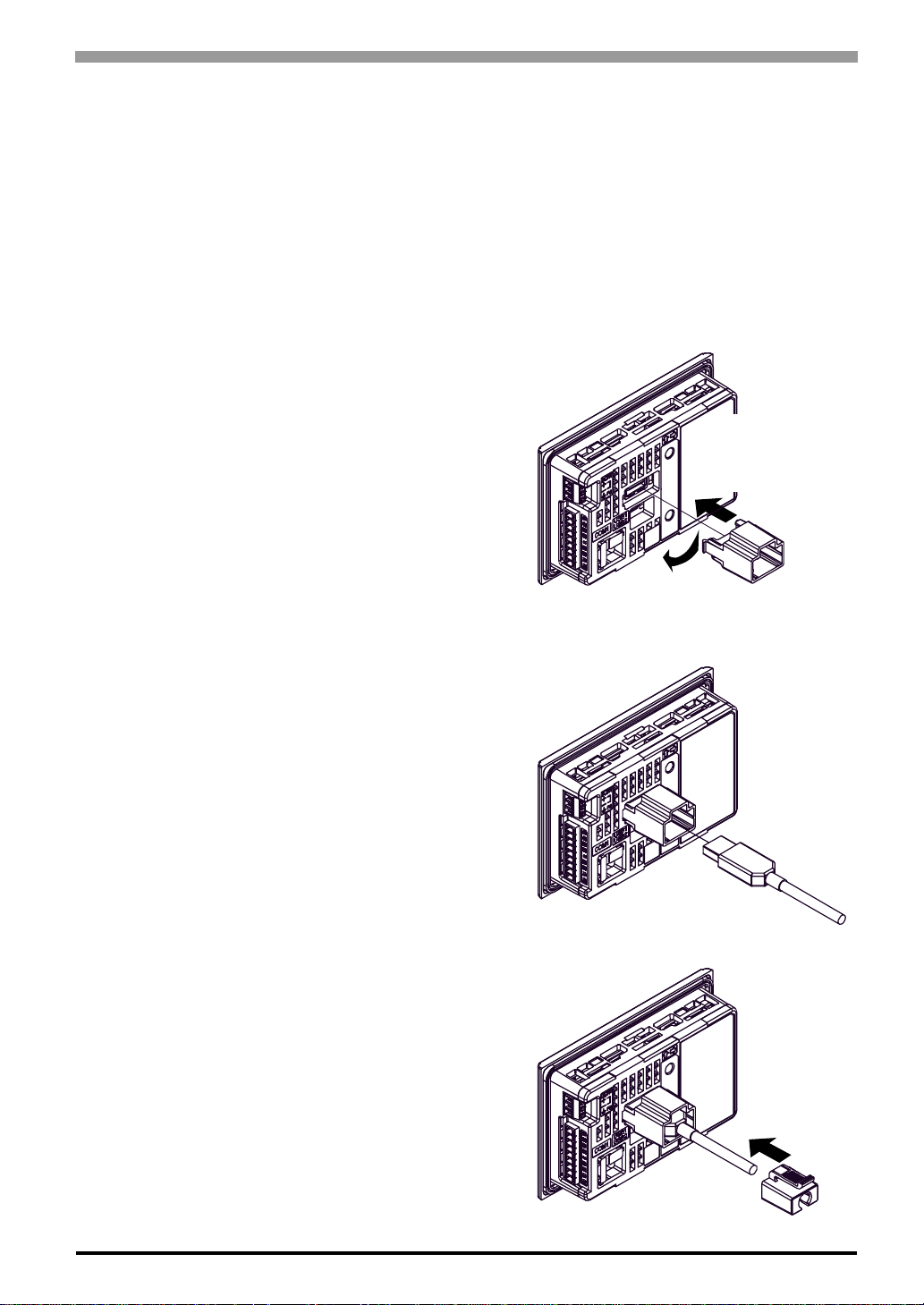
This clamp is used to prevent the USB cable connected to the USB Interface of the GP unit from being
unplugged due to vibration or other causes.
4.3.1 USB (Type A) Interface Attachment
(1) Before starting the procedure, lift down the tab of the USB Holder and remove the USB Cover.
(2) Attach the USB Holder to the USB (Type A)
Interface part of the main unit. Hook the right pick
Chapter 4 Installation and Wiring
of the USB holder to the attachment hole of the
main unit and then insert the left pick as shown to
fix the USB holder.
(3) Insert the USB cable into the USB (Type A)
Interface.
1) Hook the
right pick to
the attachment
hole.
2) Insert the left
pick to the
attachment hole.
USB holder
(4) Attach the USB cover to fix the USB cable. Insert
the USB cover into the tab of the USB Holder.
USB (Type A) cable
USB cover
4-15
Page 61
GP-4100 Series Hardware Manual
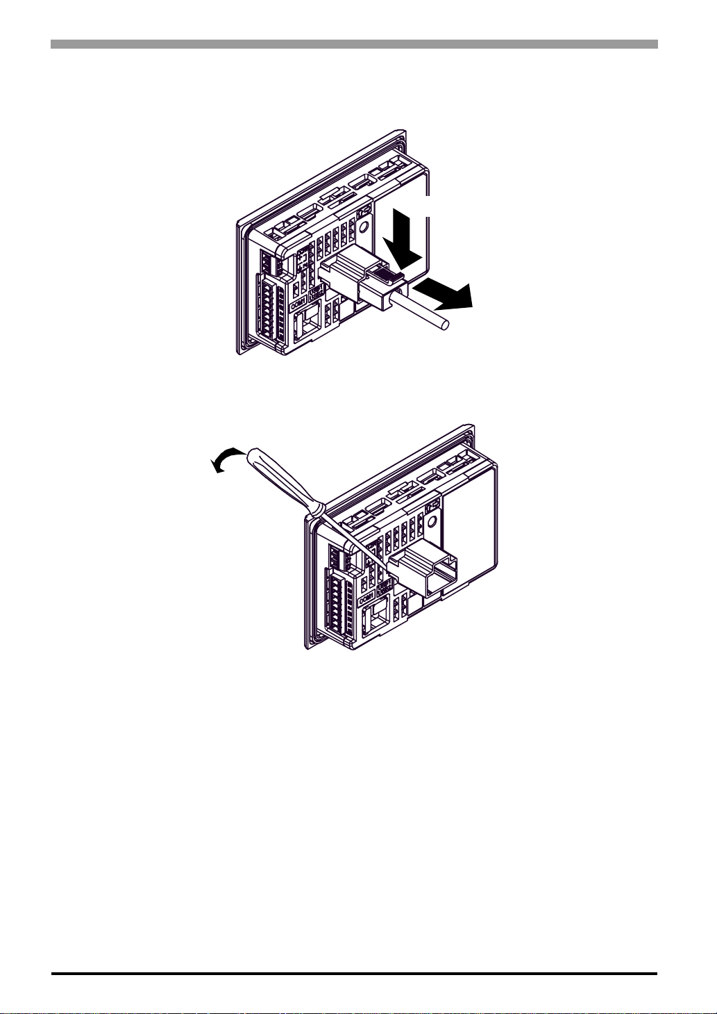
Removal
(1) Lift down the tab of the USB Holder and then remove the USB cover and the USB cable as shown.
(2) Insert a flathead screwdriver in the hole of the USB holder, as shown, and push the USB connector out
of the USB holder by lifting the tip of the flathead screwdriver.
1) Lift down the tab.
2) Remove the USB cover.
4-16
Page 62
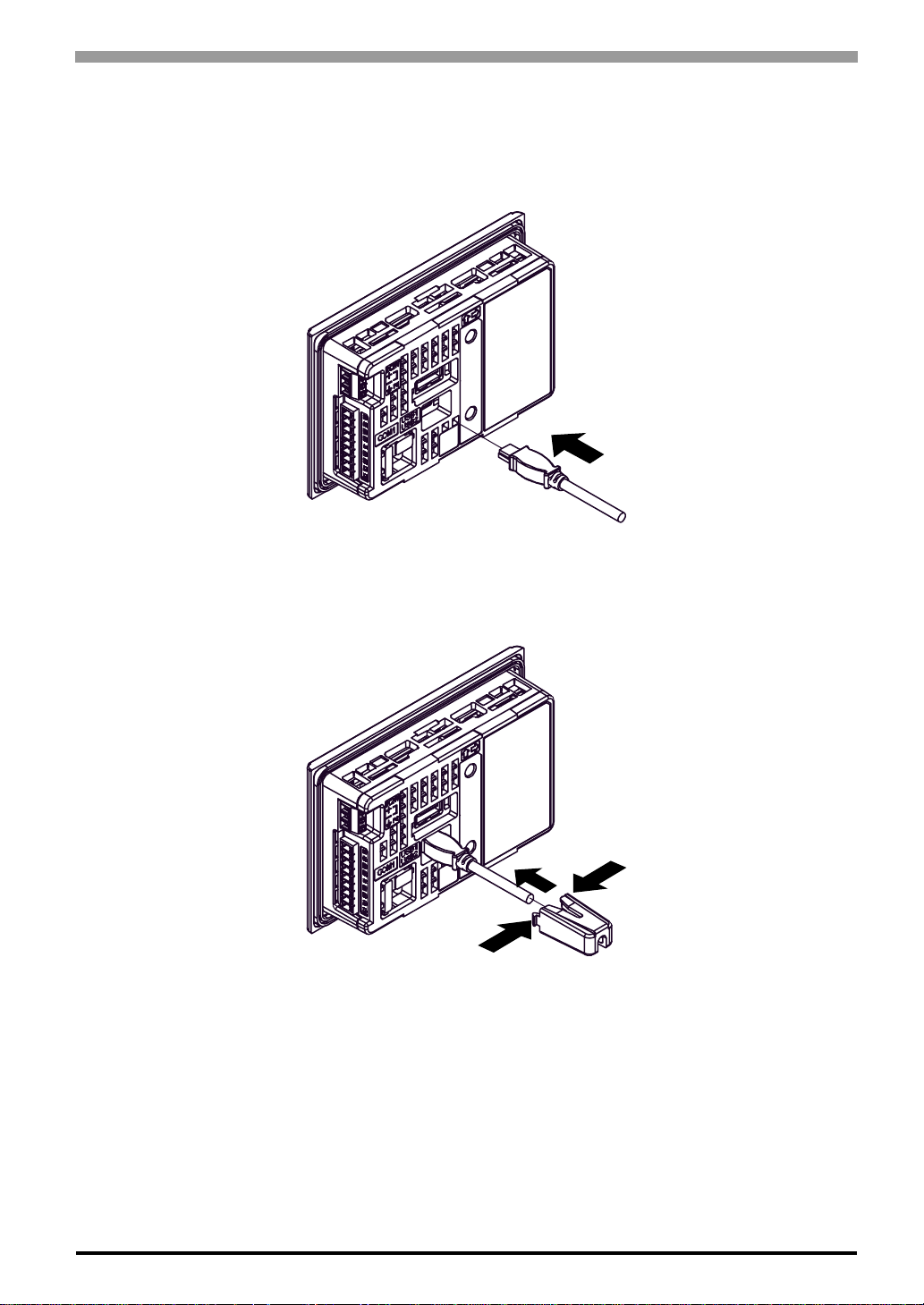
4.3.2 USB (mini-B) Interface Attachment
(1) Insert the USB cable into the USB (mini-B) interface.
Chapter 4 Installation and Wiring
USB (mini-B) cable
(2) Hold the clamp so that the USB cable can go through it. Squeeze the locking tabs on the clamp as you
insert it into the mounting hole.
2) Insert into the mounting hole.
1) Squeeze the locking tabs on
the USB clamp
4-17
Page 63
GP-4100 Series Hardware Manual
Removal
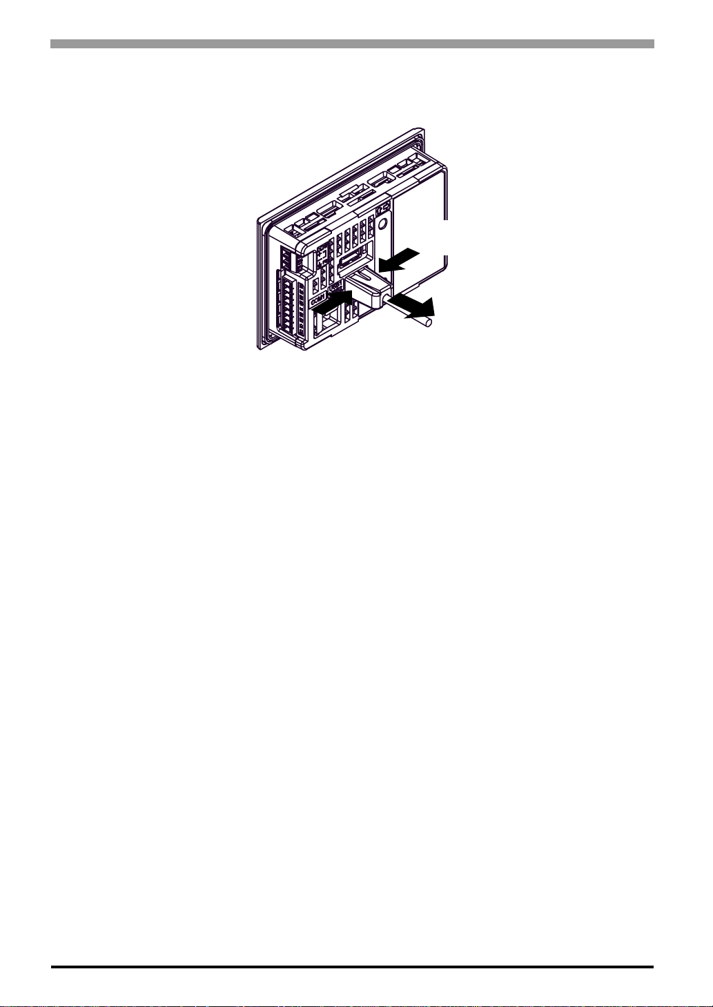
(1) The clamp can be removed by squeezing the sides of the clamp and pulling, as shown in the Figure.
1) Keep the sides of the clamp
squeezed in.
2) Pull out
4-18
Page 64

5 Maintenance
1. Cleaning the Display
2. Periodic Check Points
3. Replacing the Installation Gasket
4. Replacing the Backlight
This chapter explains cautions and inspection criteria that will ensure trouble-free use of the GP.
5-1
Page 65

GP-4100 Series Hardware Manual
5.1 Cleaning the Display
When the surface or frame of the display become dirty, soak a soft cloth in water with a neutral detergent,
wring the cloth tightly, and wipe the display.
• Do not use paint thinner, organic solvents, or a strong acid compound to clean the
unit.
• Do not use hard or pointed objects to operate the touch-screen panel, since it can
damage the panel surface.
5-2
Page 66

5.2 Periodic Check Points
To keep your GP unit in its best condition, please inspect the following points periodically.
GP Operation Environment
Is the operating temperature within the allowable range (0ºC to 50ºC)?
Is the operating humidity within the specified range (10%RH to 90%RH, dry bulb temperature of 39ºC or
less)?
Is the operating atmosphere free of corrosive gasses?
When using the GP unit inside a panel, the ambient environment refers to the interior of the panel.
Electrical Specifications
Is the input voltage appropriate?
DC19.2 to 28.8V
Related Items
Chapter 5 Maintenance
Are all power cords and cables connected properly? Have any become loose?
Are all installation fasteners holding the unit securely?
Are there many scratches or traces of dirt on the installation gasket?
5-3
Page 67
GP-4100 Series Hardware Manual
5.3 Replacing the Installation Gasket
The installation gasket provides protection against dust and moisture.
• A gasket which has been used for a long period of time may have scratches or dirt
on it, and could have lost much of its water resistance to be equivalent to IP65f /
NEMA #250 TYPE4X/13. Be sure to change the gasket at least once a year, or
when scratches or dirt become visible.
• The GP unit installation gasket’s model number is “ZC9WG31.”
Installation Gasket Attachment Procedure
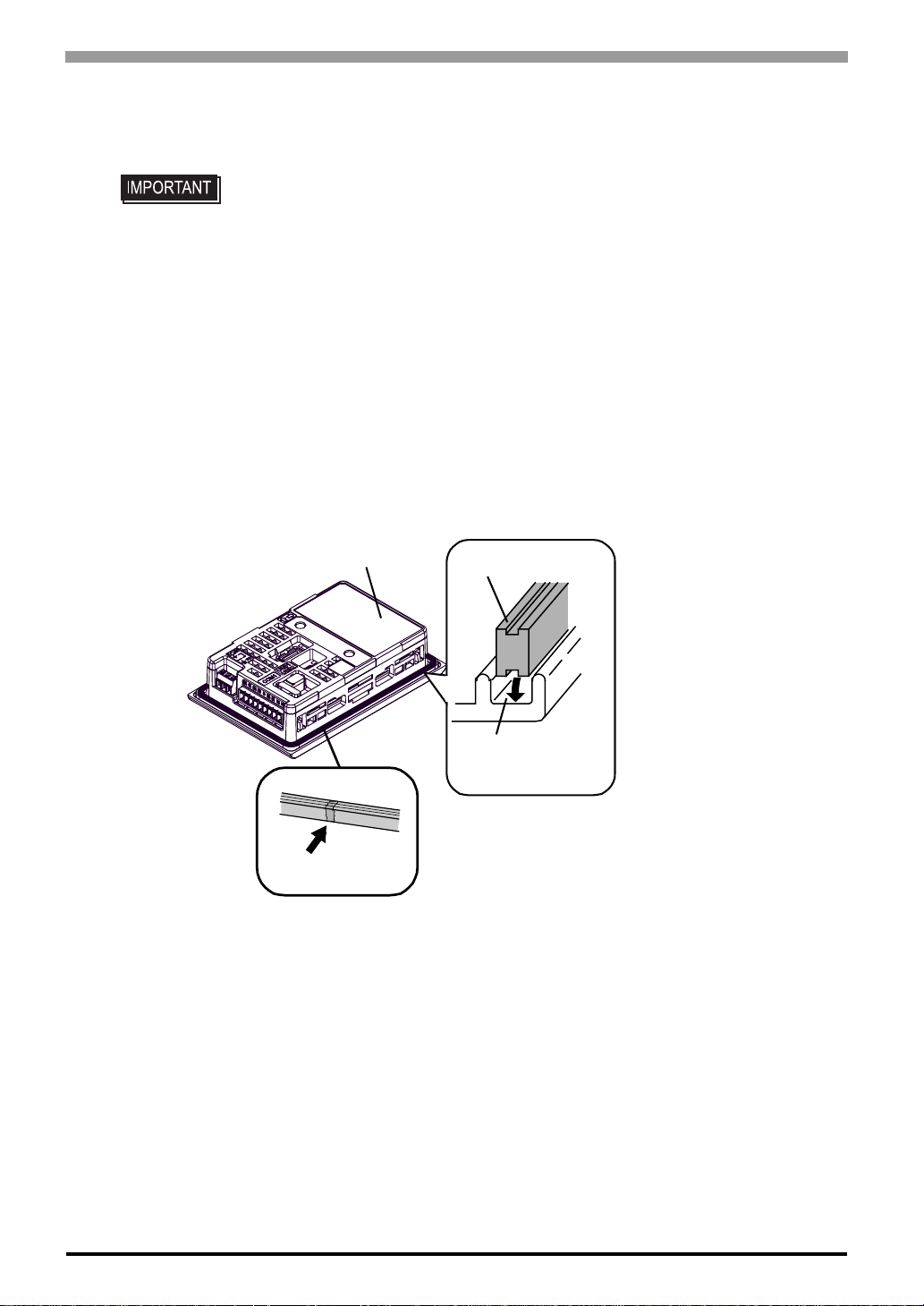
(1) Place the GP on a flat, level surface facing the display face downwards.
(2) Remove the gasket from the GP.
(3) Attach the new gasket to the GP. Be sure to insert the gasket into the GP’s groove so that the gasket’s
groove sides are vertical.
GP Rear Face
Gasket Seam
(4) Check that the gasket is attached correctly to the GP.
Gasket
Installation
Groove
5-4
Page 68
Chapter 5 Maintenance
• The gasket must be inserted correctly into the groove for the GP’s moisture resistance.
• Since the gasket is flexible but not elastic, be careful not to stretch it unnecessarily,
as doing so could tear the gasket.
• Be sure the gasket’s seam is not inserted into any of the unit’s corners, only in the
straight sections of the groove. Inserting it into a corner may lead to its eventually
tearing.
• To ensure stable resistance against dust and moisture, insert the gasket so that the
seam is at the bottom of the GP unit.
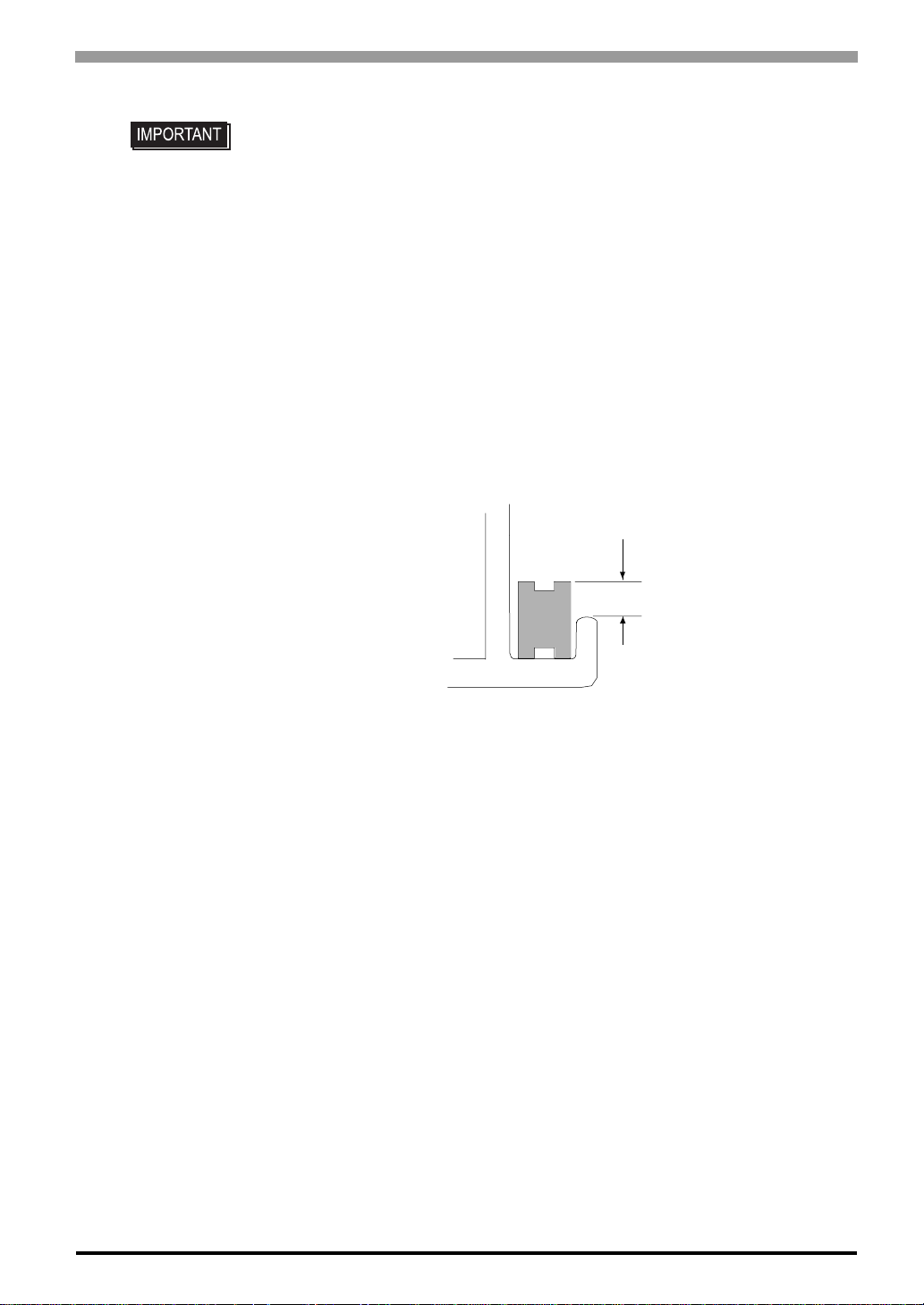
• The upper surface of the gasket should protrude approximately 2.0 mm out from the
groove. Be sure to check that the gasket is correctly inserted before installing the GP
into a panel.
2.0mm
5-5
Page 69

GP-4100 Series Hardware Manual
5.4 Replacing the Backlight
• The backlight of the GP-4100 Series cannot be replaced by the user. When the
backlight needs to be replaced, please contact your local GP distributor.
5-6
 Loading...