

Page 1

ABL-DRM03024 Installation Guide
Thank you for purchasing Pro-face’s ABL-DRM03024. To ensure correct use of
this product’s features, be sure to read this Installation Guide.
Safety Precautions
This guide contains a variety of safety markings related to safe and correct operation of the ABL-DRM03024. Be sure to read this guide carefully to fully understand how to correctly use this product’s features.
Safety Symbols
This guide uses the following symbols for important information related to safe
and correct operation of this product. Please pay attention to these symbols and
follow the instructions given.
Safety symbols and their meanings:
A hazardous situation that will result in serious
DANGER
WARNING
CAUTION
injury or even death if instructions are not followed.
A potentially hazardous situation that could result in serious
injury or even death if instructions are not followed.
A potentially hazardous situation that could result in
minor injury or equipment damage if instructions are
not followed.
DANGER
• There is a dangerous voltage inside the ABL-DRM03024.
• Any utilisation or intervention which does not comply with codes of practice can result in death,
serious physical injury or irreparable damage to equipment.
• Before any intervention, the main circuit breaker must be opened and secured against any inadvertent closing.Then wait at least 5 minutes before opening the ABL-DRM03024.
• This product is designed to be a general-purpose device for general industries, and is neither
designed nor produced to be used with equipment or systems in potentially life-threatening situations. If you are considering using this product for special uses, including nuclear power control
devices, electric power devices, aerospace equipment, medical life support equipment, or transportation vehicles, please contact your local ABL-DRM03024 distributor .
‑1‑
Page 2

WARNING
• Disconnect all the power before servicing equipment.Otherwise an electric shock may occur .
• Do not disassemble or remodel the ABL-DRM03024, since it may lead to an electric shock or fire.
• Do not use the ABL-DRM03024 in an environment that contains flammable gases, since an explosion may occur.
• Do not use the ABL-DRM03024 in an environment that is not specified in this guide. Otherwise, an
electric shock, fire, malfunction or other failure may occur.
• Because of the possibility of an electric shock or malfunction, do not touch any power terminals
while this product is operating.
CAUTION
• Be sure to install the ABL-DRM03024 according to directions in this guide. Improper installation
may cause this product to malfunction or fail.
• Be sure to wire this product according to the directions in this guide. Improper wiring may cause a
malfunction, failure or electric shock.
• Do not allow foreign substances, including chips, wire pieces, water, or liquids to enter inside this
product’s case. Otherwise, a malfunction, failure, electric shock or fire may occur .
• Be sure this product is operated only by personnel trained in control system programming and
design.
• Do not touch this product with wet hands or wipe it with a wet cloth. Doing so may cause a fire or an
electric shock.
• Be sure to install a fuse, breaker etc. in each of the power, input and output circuits. Failure to do so
can lead to a fire if an overload occurs.
• When disposing off this product, be sure to do so according to your country’s standards for industrial waste disposal.
To Prevent ABL-DRM03024 Damage
• Do not store or operate the ABL-DRM03024 in either direct sunlight or excessively dusty or
dirty environments.
• Because this product is a precision instrument, do not store or use it in locations where excessive shocks or vibration may occur.
• Do not cover this product’s ventilation holes, or operate it in an environment that may cause it to
overheat.
• Do not operate this product in locations where sudden temperature changes can cause condensation to form inside this product.
• Do not use paint thinner or organic solvents to clean this product.
Paralleling
• The parallel connection of the ABL-DRM03024 makes it possible to output the double current
only when two pieces of ABL-DRM03024 are paralleled.
• In order to improve heat dissipation, be sure not to set two ABL-DRM03024 in contact with
each other. In any condition, please make space at least 50mm(1.97 inch) on top and bottom
of this product and 15mm(0.59 inch) for both sides of this product.
• Set the same output voltage of each ABL-DRM03024 separately by adjusting [V Out] before
plugging them together.
‑2‑
Page 3
1
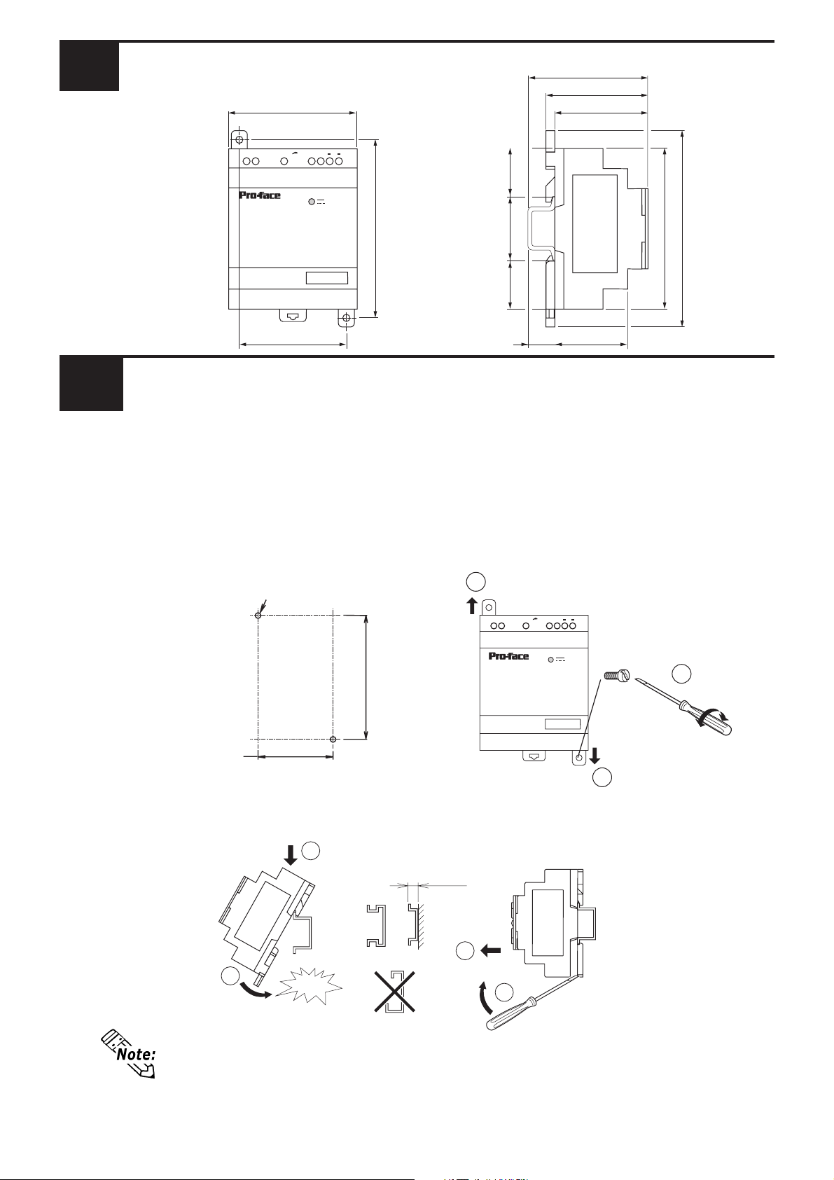
Dimensions
Unit: mm [in.]
72mm[2.83]
Input
100 -240VAC
ABL DR M 03024
70mm[2.76]
59.5mm[2.34]
55mm[2.17]
V OutNL
++
Output
24VDC-1.3A
100mm[3.94]
27.5mm
[1.08]
35mm
[1.38]
27.5mm
[1.08]
90mm[3.54]
110mm[4.33]
60mm[2.36]
2
Installation
Direct Panel Installation
15mm[0.59]
44mm[1.73]
Create two attachment screw holes using the dimensions shown below, and position this product so that its product attachment tabs (Top and bottom) align with
the attachment screw holes. Secure the product in place using M4 attachment
screws, using a torque of 1 N•m. For the efficient use of the ABL-DRM03024,be
sure to install this product as shown below.
1
Unit: mm [in.]
+0.2
60
DIN Rail Installation
[2.36 ]
-0.2
+0.01
-0.01
2-M4
+0.01
-0.01
[3.94 ]
+0.2
-0.2
100
Input
100 -240VAC
ABL DR M 03024
V OutNL
++
Output
24VDC-1.3A
M4×20
2
1
Confirm that the DIN rail fastener hook is clipped in place and the module is held securely.
Unit: mm[in.]
Installation
2
When attaching the ABL-DRM03024 to a panel, extend the product’s attachment tabs. When attaching the ABL-DRM03024 to a DIN rail, retract the
product’s attachment tabs.
1
snap
7.5[0.30]or more
Removal
2
1
‑3‑
Page 4
3
Specifications
Item Specifications
Input V oltage AC100 to 240V
Allowable Voltage Range AC85 to 264V
Allowable Frequency Range 47Hz to 63Hz
Nominal Current 1.3A
Output voltage DC24V
Output Power 31W
4
Wiring
The following types of wires can be used:
Wire Type Pin -type Terminal La y wire Simple W ire
mm
AWG
2
*1
0.14 to 1.5 0.14 to 2.5 0.14 to 4
26 to 16 26 to 14 26 to 12
*1 AWG stands for “American Wire Gauge” and indicates conductor thickness.
• Strip the wire’s plastic covering to expose approximately 6.8mm of wire.
• When using a lay wire, Pro-face recommends you install a pin-type terminal
connector.
• The torque required to secure a wire to a terminal is 0.6 N•m.
5
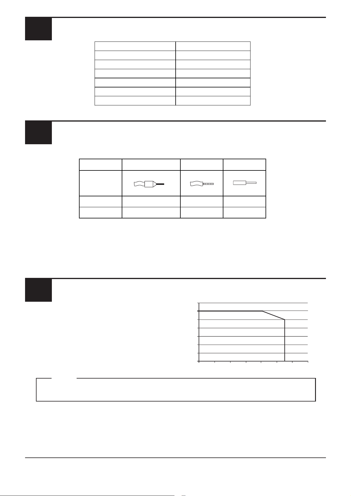
The ambient temperature and the power supply
P/Pn(%)
The graph shows the power (in relation
to the nominal power) which the ABLDRM03024 can deliver continuously,
according to the ambient temperature.
Maximum operating temperature()
Note
Please be aware that Digital Electronics Corporation shall not be held liable by the user for
any damages, losses, or third party claims arising from the use of this product.
Digital Electronics Corporation
8-2-52 Nanko Higashi, Suminoe-ku, Osaka 559-0031, Japan
TEL: +81-(0)6-6613-3116
FAX: +81-(0)6-6613-5888
URL: http://www.pro-face.com/
© 2005 Digital Electronics Corporation
‑4‑
 Loading...