

PROEL PROEVAC EVO EV PROM5Z User And Installation Manual

PROEVAC EVO
EN54-16 Voice Alarm System
USER AND INSTALLATION MANUAL

This page is intentionally left blank
Firmware revision: 1.10.12.13
Document: USRM_PROEVAC EVO_IT_14 Rev. 0.01
Issued by: MF
Checked by: PF
Approved by: RF
Revision History
Rel.
Data
Author - Modifications
1.00
10/10/15
Translation from mother language manual Rev 3.00
Certified Quality Management System
ISO9001:2008
Reg. N. 50 100 5745

This page is intentionally left blank

CONTENTS
1. GENERAL DESCRIPTION
1.1 Introducion
1.2 List of main features and functions
1.3 System access
1.4 Explanation of symbols
2. SAFAETY INSTRUCTIONS AND CARE OF THE PRODUCT
3. VISUAL IDENTIFICATION OF CONNECTIONS AND USER KEYS
3.1 EV PROM5Z Master unit
3.2 EV PROS8Z Slave unit
3.3 EV MCL1Z Line-A main controller module
3.4 EV MCL2Z Line-B redundant controller module
3.5 Micriphone stations
4. DESCRIPTION OF CONNECTION AND SYSTEM ASSEMBLY
4.1 Power supply connection
4.2 Installation of the line modules in Master and Slave units
4.3 Connection of the Master unit to one or more Slaves
4.4 Spare amplifier wiring on Master and Slave units
4.5 Wiring the line A module
4.6 Wiring the line B module
4.7 Wiring and configuring the microphone stations
4.8 Replacing the clock battery
4.9 uSD memory card installation
4.10 Completing the system
5. DESDCRIPTION AND IDENTIFICATION OF THE SYSTEM STATUS
6. SYSTEM MENU
6.1 Menu navigation
6.2 Menu tree
6.3 Description of the system’s menus
6.4 Logs table
7. OPERATIONS AND PROCEDURES
7.1 Access levels authentication
7.2 Silencing a zone
7.3 Calibrating a line
7.4 Restoring the primary amplifier
7.5 Background music volume
7.6 Cancelling the logs
7.7 System inticators test
7.8 Setting date and time
7.9 Configuration download
8. USING THE MICROPHONE STATIONS
8.1 Common features to all models
8.2 EV BME1T
8.3 WG-MTU06
8.4 EV BME10T
9. TECHNICAL SPECIFICATIONS
10. CERTIFICATIONS

1. GENERAL DESCRIPTION
1.1 Introduction
Proevac is a modular, digitally controlled, voice alarm system. It’s main purpose is to send spoken, live or recorded, voice
evacuation messages. Proevac was designed and certified according to EN 54-16 specification in order to grant a high quality and
high intelligibility sound.
The modularity and scalability of Proevac allow to configure it in order to be tailored according to the building requirements
thanks to the high number of zone that can be fitted and thanks to the high output power that can be handled by each zone.
The internal four channelmatrix arrangement allow to sent up to four audio contents or general purpose audio messages on
different group of zones.
The system core is the Master EV PROM5Z unit that manages all audio flows and performs the monitoring of the whole setup. All
functions related to the each zone are managed by the EV MCL1Z modules that are fitted into the Master EV PROM5Z and Slave EV
PROS8Z units and connected to an external power amplifier. Thus, each zone has its own dedicated power amplifier that is
managed independently from all others. This feature allows to set up each zone with a power amplifier that b est suits the design
demands of the electrics of the building with a power handling up to 500 Wrms.
The EV PROM5Z Master unit can handle up to 5 zone controller modules and EV PROS8Z Slave unit can be fitted with up to 8 zone
controllers. Slave units are daisy-chained to the Master allowing thus to configure the system up to 108 zones.
Additionally, each Master and Slave unit can handle a spare amplifier that switches over in case of a failure to a zone amplifier.
Each EV MCL1Z zone controller has an embedded memory where two independent messages are stored. Recorded messabes are
triggered by two monitored input contacts. This particular feature allows to send a dedicated alarm message on each single zo ne.
This means that in case of a fire alarm on a 108 zones system, the equipment will play 108 different messages all together.
Finally, each zone module has its own independent volume and tone control.
The monitoring of the loudspeaker line and related power amplifier is achieved with a tone above the audio band through a FFT
algorithm that allows the system to constantly keep under control both amplifier and loudspeakers without interfering with the
voice message or background music that is being played and without them to interfere with the monitoring itself. The monitoring
is so accurate that it able to catch very small variations of the applied load thanks to a sophisticated algorithm that follo ws and
compensates both environmental parameters and load drifts. The monitoring functions of the EV MCL1Z module include a
detection of ground leakage of the loudspeaker line.
Where the design of the voice alarm system foresees loudspeaker line redundancy on some (or all) zones, the main EV MCL1Z zone
controller can be matched to the secondary line controller EV MCL2Z. The main line controller drives and monitors the power
amplifier and manages the first loudspeaker line (line A) while the secondary zone controller takes power from the same amplifier
and distributes it to the second loudspeaker line (line B) performing load and impedance monitoring. In case of a failure to one of
the two lines, the faulty line is disconnected and power is eventually increased on the healthy line in order to maintain a constant
sound pressure inside the room.
All sound contents are processed by the EV PROM5Z Master that acts as a central sorting device from the inputs to the zone
controllers. The master unit has two input ports from two independent groups of microphone stations connected in parallel in a
bus fashion. Each bus carries audio, data channel and power. The Master unit constantly monitors the performance of the
microphone stations through an integrity check of the communication bus. All microphone stations of the Proevac system can be
configured as a voice alarm call station, or for general announcements. In the first case, if a failure occurs in whatever part of
audio or data path, from the microphone capsule to the Master unit, the system will promptly report a fault.
Proevac has different models of microphone stations: EV BME1T and WG-EFM10 have a single direct access key and are typically
used desktop or wall-mount emergency call stations. WG-MTU06 and EV BME10T allow superior flexibility thanks to their
advanced user interface and are both configurable for general announcements or as emergency call stations.
The functions of all microphone station, their access priority to the zones of the system is defined at the time of the configuration
of the whole system through the BEST (“Basic voice Emergency Setup Tool”) software.
In addition to all described functions, the Proevac system can play two or more recorded alarm messages that are common to all
zones. These messages are triggered by two monitored inputs on the master unit. The master unit as an embedded scheduled
message player for non-fire-alarm purposes that may be useful, for example in a shopping mall to play commercials, welcome
announcements, etc… Finally, the EV PROM5Z master unit has dedicated relay outputs for state reporting to other fire devices,
dedicated inputs to report the state of an external power supply and a background music RCA input.
1.2 List of main features and functions
Digitally controlled and configurable voice alarm and public address audio system; up to 108 zones
4 lines matrix arrangement
2x independent messages for each zone stored inside a mass memory on the EV MCL1Z module
Unlimited number of addressable messages, up to the storage capacity of the internal uSD card
2x monitored input contacts on EV PROM5Z master unit and 2x monitored input contacts on each EV MCL1Z for alarm or
general purpose message triggering
Continuous and independent monitoring of each zone loudspeaker line and power amplifier performed by the EV MCL1Z module
Continuous and independent monitoring of redundant loudspeaker line (line B) performed by EV MCL2Z module
Continuous and independent monitoring of redundant loudspeaker line ground leakage
Automatic calibration of loudspeaker lines and load applied to the power amplifier volume
Automatic output level setting of the power amplifier to reach 100V on loudspeaker line
Spare amplifier connections on EV PROM5Z master and EV PROS8Z slave units
Independent volume and tone control over each zone
Independent volume and tone control of each audio content, general or alarm
Enablement, volume and tone control of background music on each zone.
Five level priority management of ever audio content addressable to zones or group of zones
System functions and configuration on password protected access levels according to EN54-16 requirements
Acoustic and visual reporting of the system’s status
Alarm message silencing independently on each zone.
Up to 54 microphone stations on two independent busses. A total of 108 microphone stations are allowed.
Continuous monitoring of audio path of all microphone stations; all models can be used as alarm call stations or for general
announcement purposes.
Automatic logging of all system’s events on the internal uSD memory card.
Conversion of all digital audio formats on the BEST software.
Automatic validation of the hardware setup and congruency with the designed system in the BEST software.
Extension slot on the EV PROM5Z Master unit.
2x input contacts for power supply state reporting
2x replay contacts for state reporting to other devices
1.3 System Access
Accessing the system is allowed to predefined figures only. These are identified inside this manual by the following symbols that
are associated with their respective duties.
Access to functions which refer to the three figures listed here is password protected.
ACCESS LEVEL 3: INSTALLER or MAINTAINER
is the one who defines the system configuration, performs site-specific system design, wires the system and/or takes
care of the technical support.
ACCESS LEVEL 2: SECURITY GUARD
all persons having a specific responsibility for safety and who are trained and authorized to operate the system.
ACCESS LEVEL 1: USER
is a member of the general public or person having a general responsibility for safety supervision who might be
expected to investigate and initially respond to a fire alarm od fault warning.
NOTE: The access restrictions to the system by the three figures listed above are not exclusive, but are intended as cascaded.
The user is only allowed to access level 1, the security guard is allowed to access levels 1 and 2, and the installer can access
all levels.
1.4 Explanation of symbols
In addition to the symbols that identify the persons allowed to operate the system, below are some icons that will focus on
important aspects and features related to the system.
USEFUL INFORMATION
This symbol identifies an information that may be useful in the use or configuration of the system.
TIP
This symbol identifies a tip or an application example.
WARNING/DANGER
This symbol indicates a specific aspect, feature or action that requires special care or attention since a negligence
would lead to a situation of danger, malfunction or deterioration in the performance of the system.
ELECTRIC SHOCK
This symbol indicated a situation in which the user/maintainer/installer may be exposed to a risk of electric shock
2. SAFETY INSTRUCTIONS AND CARE OF THE PRODUCT
These instructions are for use by qualified service personnel that shall perform the installation and servicing of the units of the Proevac
system.
Please, read carefully this user manual and the safety instructions related to the product.
Keep these instructions and the product user manual
Heed all indications contained herein and in the user manual
ELECTRIC SHOCK
In order to reduce the risck of electric shock, do not remove the top cover of the unit or the covers/modules on the
back of the unit when the equipment is powered.
Remove the top cover to access the inside of the units only when the equipment is unpowered
Do not perform any servicing operation that is not contained in the operation instructions.
WARNING
Do not expose the unit to moisture or rain.
Install the equipment so that no liquids flow inside
Do not locate near objects filled with liquids that may accidentally pour on the equipment.
Do not block any ventilation openings. During installation, please ensure that the units are sufficiently ventilated.
Do not install the equipment near heat sources such as radiators, heat registers, stoves or the apparatus (including
amplifiers) that produce heat.
CARE AND MAINTENANCE
Unpower the equipment before performing any of the following operations:
Clean the equipment with a dry cloth
Check periodically the ventilation opening for obstructions and dirt.
Clean the ventilation openings with a vacuum-cleaner
Check periodically all cables and connections.
Check periodically the presence and effectiveness of ground connection.
FAILURE OR DAMAGE
Contact your delaer or qualified service center in case the equipment is found damaged or in case of a failure such
as:
Unit has been dropped or exposed to mechanical shock.
Unit shows a state of decay or alteration of performance.
A foreign object is detected inside the equipment.
Liquid has been spilled inside the equipment.
Unit has been exposed to rain or moisture
Cables or connectors carrying power (power supply, amplifier outputs or speaker lines) are damaged.
BATTERY SUBSTITUTION
The EV PROM5Z unit has a CR2032 battery for the internal real time clock and calendar. It is advisable to change the
battery every 24 months. Please refer to user manual for detailed instructions.
CHECK OF LOUDSPEAKER LINE IMPEDANCE DRIFT
In order to check the loudspeaker lines impedance drift with respect to the initial calibration, it is advisable to
periodically reset the equipment by unpowering and powering it. The time between one reset operation and another
is the responsibility of the safety officer based on the assessments of the risks for the building. We, the
manufacturer suggest to perform a reset operation once every 12 months.
AUTHENTICITY OF THE USER MANUAL AND RELATED DOCUMENTATION
This manual is an integral part of the Proevac system, designed and manufactured by Sotis Engineering Srl. His
presence in paper and/or electronic form is guaranteed by the manufacturer during the packaging of the product.
Sotis Engineering disclaims any liability, direct, or indirect, about the product and any other equipment connected
or wired to it in case the system is configured and operated referring to other manuals or documentation different
than the present, or whenever this manual, related documents and application notes, are issued or modified by third
parties without the authorization of Sotis Engineering. It is therefore expressly forbidden by anyone to alter or make
changes of any kind in this manual.

3. VISUAL IDENTIFICATION OF CONNECTIONS AND USER KEYS
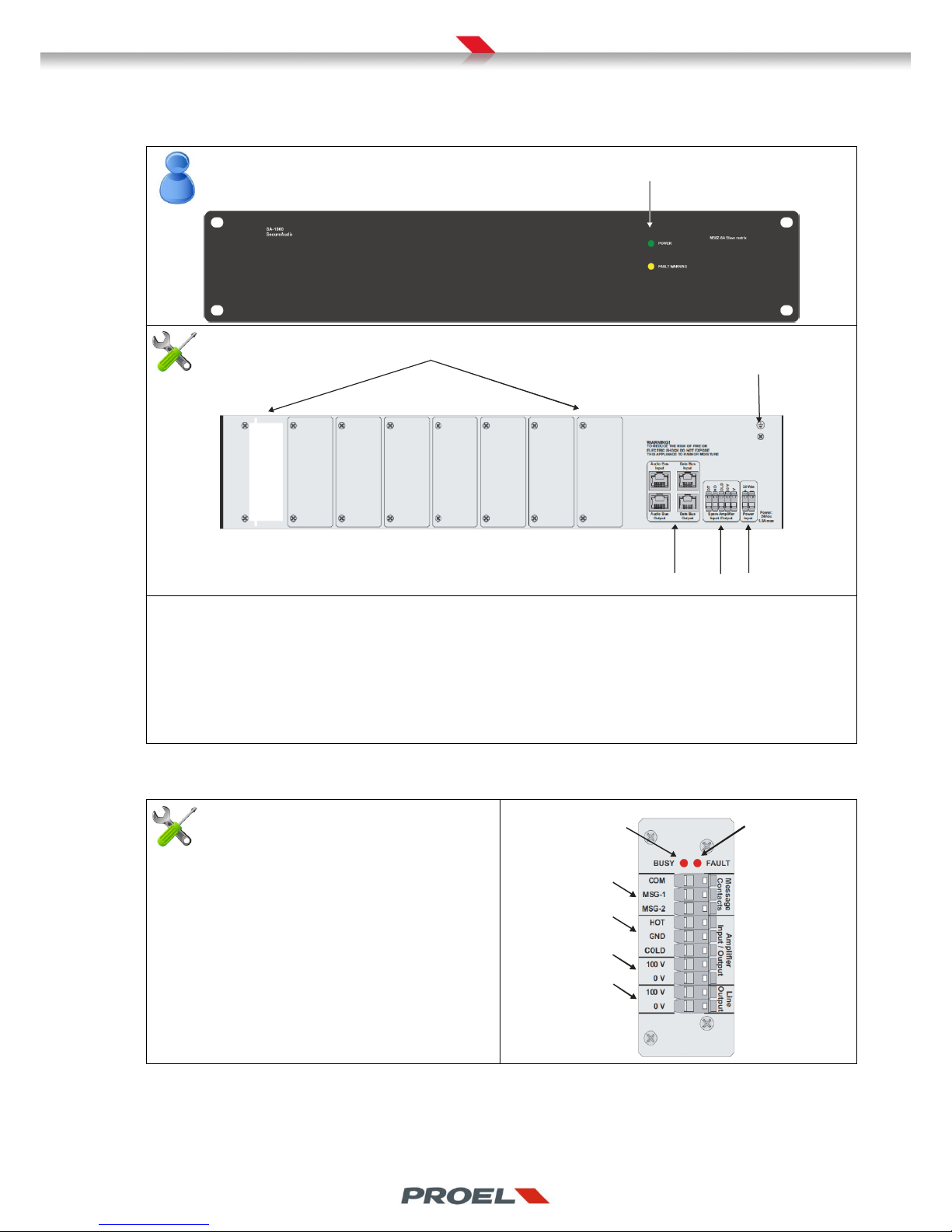
3.1 EV PROM5Z Master unit
EV PROM5Z Front panel
EV PROM5Z Rear panel
5
6 7 8 9 10
11 12
13 14 15 16 17
1. Dot-matrix display.
2. Navigation keyboard to access menus and system functions
3. Status leds: “POWER” indicates that the system is powered and operational, “VOICE ALARM indicates that the system is
in a voice alarm state and that he is playing and evacuation message, “FAULT” indicates that a fault is present in the
system itself or in another device of the voice alarm system connected to it (i.e. power amplifiers, loudspeaker lines,
mic stations and wires)
4. USB port for system configuration download.
5. Zone modules slots (EV MCL1Z, EV MCL2Z) o for future use.
6. Monitored contacts to trigger recorded voice alarm messages
7. Relay output that indicates a voice alarm (N.C. contact).
8. Relay output that indicates the system is playing a general announcement (N.O. contact).
9. Slot dedicated to future uses.
10. Ground connection
11. Input contacts to report the state of an external power supply
12. Relay output that indicates a system fault. (N.O./N.C. contact).
13. Background music input.
14. Microphone stations Bus 0 and Bus 1.
15. Connections to EV PROS8Z slave units.
16. Spare amplifier connections.
17. 24Vdc power input.
3.2 EV PROS8Z Slave unit
WG -ESU08 Front panel
1
EV PROS8Z Rear Panel
2
3
4 5 6
1. Status leds: “POWER” indicates that the unit is powered and operational, “FAULT” indicates that a fault is present in the
system itself or in another device of the voice alarm system connected to it (i.e. power amplifiers, loudspeaker lines,
mic stations and wires)
2. Zone modules slots (EV MCL1Z, EV MCL2Z) o for future use.
3. Ground connection
4. Chain connections from EV PROM5Z master and to other EV PROS8Z slave units
5. Spare amplifier connections.
6. 24Vdc power input.
3.3 Line controller module (line A) EV MCL1Z
1. LED “BUSY”: indicates the zone is playing and audio
content
2. LED “FAULT”: indicates a fault related to the
loudspeaker line.
3. Monitored input contacts to trigger alarm messages.
4. Balanced audio output to the power amplifier
5. 100V power input (connect to power amplifier
output)
6. 100V loudspeaker line output
EV MCL1Z connections
1
2
3
4
5
6
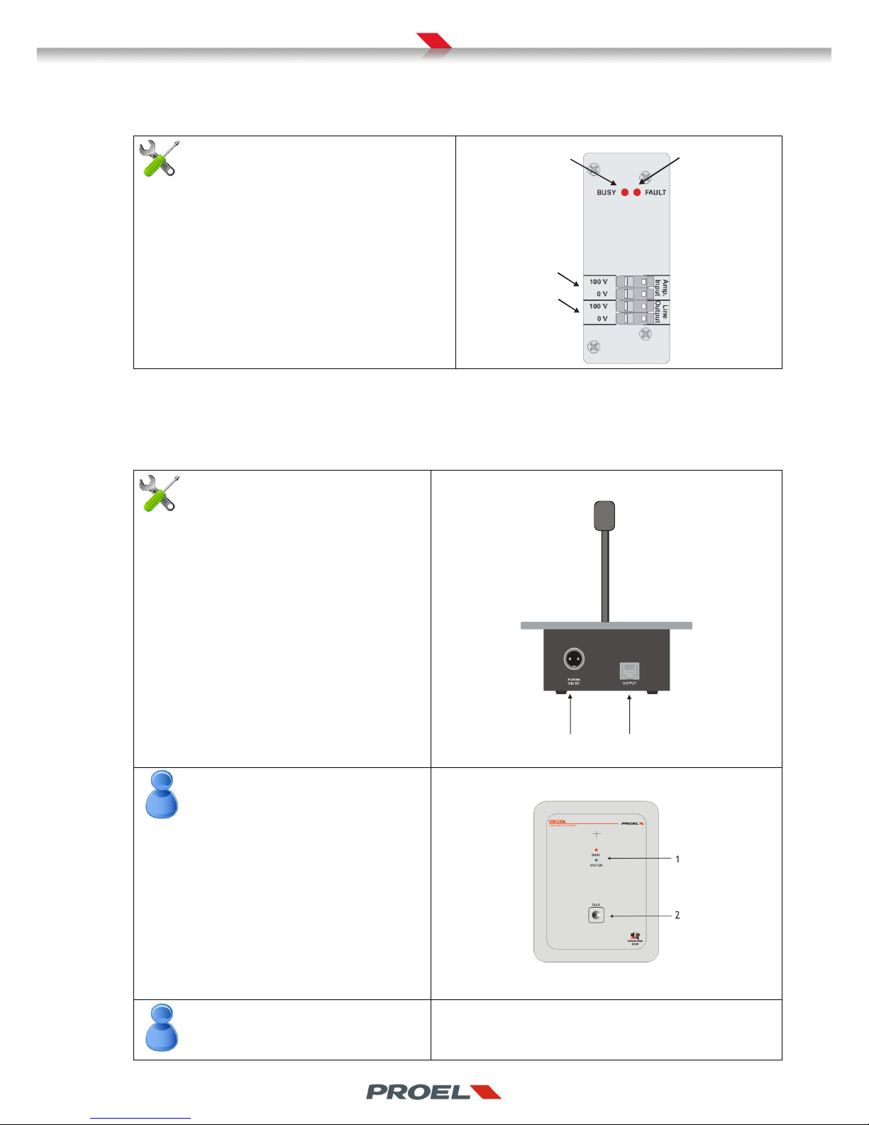
3.4 Line controller module (line B) EV MCL2Z
1. LED “BUSY”: indicates the zone is playing and audio
content
2. LED “FAULT”: indicates a fault related to the
loudspeaker line.
3. 100V power input (connect to power amplifier
output).
4. 100V loudspeaker line output
EV MCL2Z connections
1
2
3
4
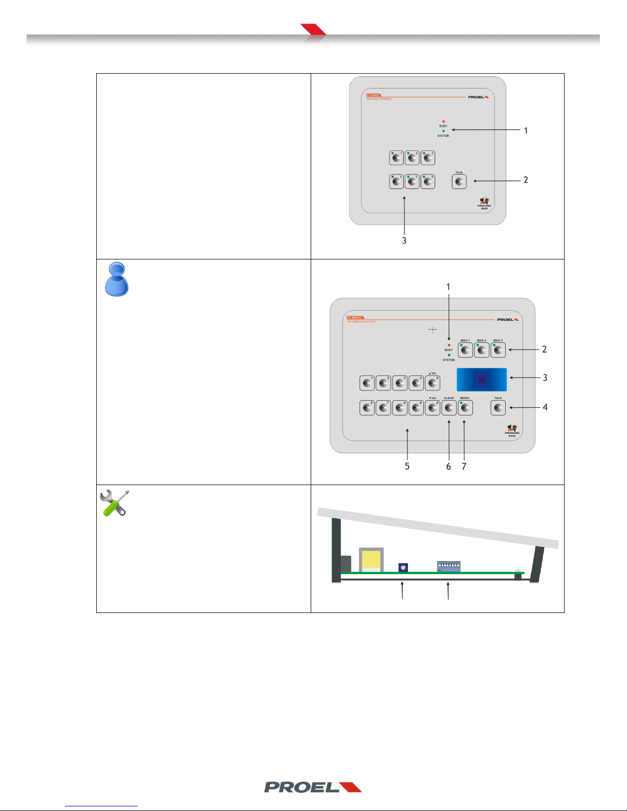
3.5 Mircophone stations
1. Audio, power and data bus. Connect to
dedicated ports on EV PROM5Z
2. Auxiliary power input
Microphone stations rear panel view- all models
1
2
1. Status leds indicate the status of the system
2. “TALK” pushbutton engages the bus and the
loudspeaker lines to forward the audio content.
EV BME1T top panel view
EV BME6T
1. Status leds indicate the status of the system
2. “TALK” pushbutton engages the bus and the
loudspeaker lines to forward the audio content
previously selected with 3) keys.
3. Zone selection keys on which the microphone
channel is opened. The keys are assigned to the
zones (or groups) through a configuration in the
BEST software. The led close to each key
indicates the zone or group is selected.
1. Status leds indicate the status of the system
2. Quick selection keys of pre-recorded messages.
The led close to each key indicates message is
selected
3. Dot matrix display
4. “TALK” pushbutton engages the bus and the
loudspeaker lines to forward the audio content
previously selected with 5) or 2) keys.
5. Zone selection keys on which the microphone
channel is opened. The keys are assigned to the
zones (or groups) through a configuration in the
BEST software.
6. Clear selection key
7. Background music volume control enablement.
Volume may be changed with UP and DOWN
keys.
EV BME10T top panel
1. Microphone gain trimmer
2. Address selections and data line tarmination
dip-switch
Internal side view of all microphone stations
2
1
4. DESCRIPTION OF CONNECTIONS AND SYSTEM ASSEMBLY
This entire section is dedicated to installer/maintainer only
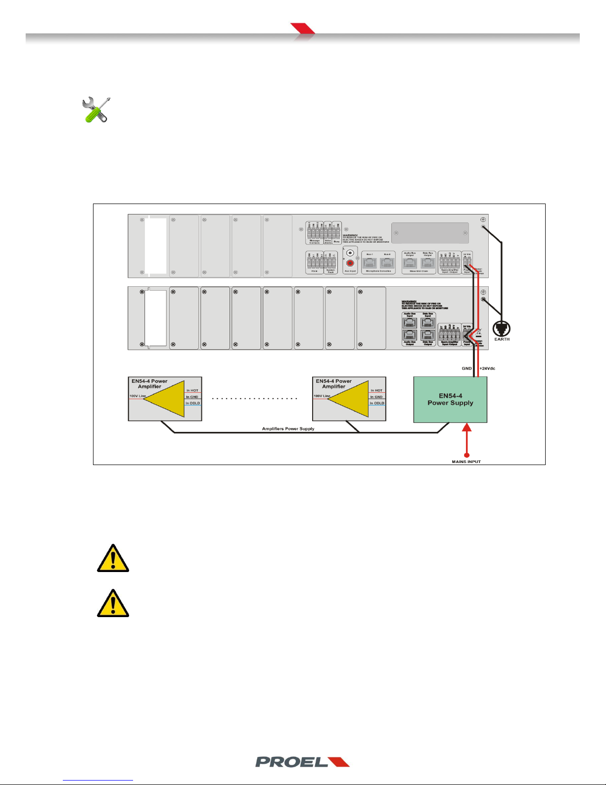
4.1 Power supply connection
The EV PROM5Z master and EV PROS8Z slaves (if present) must be powered by a 24dv power source coming from an certified EN544 power supply and according to the diagram here below. The sizing of the 24dc line shall take into account the current absorbtion
of master, slave unit, microphone stations and zone modules. Please refer to the technical specifications section for these details.
Power amplifiers shall be also powered by, or shall integrate, an EN54-4 power supply.
Wiring of power supplies – Master, slaves and amplifiers.
The figure above show explicitly the positive and negative connection of the power line that feeds the Proevac system.
The power supply line to the amplifies is shown schematically. Please refer to the manuals of power amplifiers and power supply.
Proevac requires a ground connection between the Master (and slaves of present) and the chassis of the rack cabinet where the
system is installed. The rack cabinet must be connected to a strong earth connection of the building.
It is recommended to periodically check the earth connection with appropriated instruments in order not to affect
the performance of the system.
Proevac’s electrical ground (negative pole of system power) is connected to the chassis.

4.2 Installation of the line modules inside the Master EV PROM5Z and Slave EV PROS8Z units
The Master unit has five vertical slots on the back to be fitted with EV MCL1Z and/or EV MCL2Z line controllers. It is essential that
the slots are filled, starting from the left, in the order shown on the figure below.
The figure also shows a valid and a not allowed configuration.
Filling of the zone slots
Allowed and valid setup
Not allowed setup
The Slave unit has eight vertical slots on the back to be fitted with EV MCL1Z and/or EV MCL2Z line controllers. It is essential that
the slots are filled, starting from the left, in the order shown on the figure below.
The figure also shows a valid and a not allowed configuration
Filling of the zone slots
Allowed and valid setup
Not allowed setup
In case you configure a system with a master and one or more slave units, it is not mandatory that the units have all slots loaded.
It is possible and allowed to partially load the master and continue the installation of other line modules inside the first slave, that
on its turn may not be entirely filled and thus additional modules may be fitted in the second slave, etc…
A unit (master or slave) may be even left empty! This gives the system a great configuration flexibility in terms of distribution of
the risk of a failure of a loudspeaker line or power amplifier. To best illustrate this feature, please refer to the following
application note where a 8 zones system setup is analyzed.
APPLICATION NOTE – 8 ZONES SYSTEM
An 8 zones system (with lines A only) is a significant case of study since it is possible to configure Proevac in different
ways according to the requirements of the voice alarm equipment for a specific building. The requirements may be in
favor of the best effort in case of a failure, or look after the best cost/performance ratio. Balancing the risk of a failure for the
Proevac system in this application note, goes through an assessment of the possibility of a fault of one of the main power
amplifiers. As mentioned previously, the master and slave units have the possibility to manage a spare amplifier that will switch
over in case of a failure to the main power amplifier managed by one of the line modules fitted in the unit. Proevac has the
flexibility to optimize the setup in order to achieve the best compromise in terms of cost effectiveness and risk, or at the
extremes, it is possible to configure the system for a maximum economy (with one or no spare amplifiers), or for a minimum risk
with a spare amplifier for each zone, but at a higher cost.
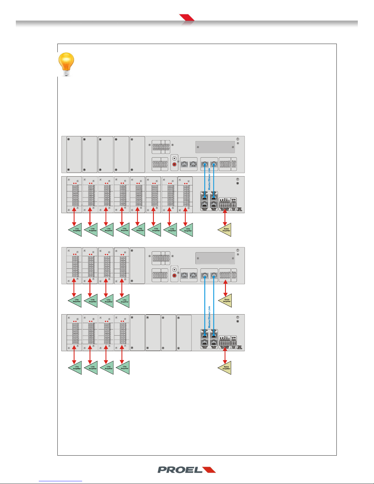
The figure here on the left, describes
an 8 zones, low budget system, but at
the expense of a higher risk. In fact, it
is foreseen only one spare amplifier
(yellow) that will switch over the first
of the eight main amplifiers that will
fail. If a second main amplifier will fail,
no spare amplifier will be available
since it is already in use.
The figure here on the left, describes
an 8 zones system where a good
balance between risk and cost is
achieved thanks to two spare
amplifiers. Four zone modules are
fitted in the master and four in the
slave. Each group of four is served by a
spare amplifier.
Continuing with this logic, it is possible to furtherly distribute the risk by setting up the same 8 zones with one master, t hree
slaves, with two zone modules each and four spare amplifiers. Each spare amplifier will eventually serve just two zones:
Master EV PROM5Z + 2x EV MCL1Z modules + spare amplifier
Slave EV PROS8Z + 2x EV MCL1Z modules + spare amplifier
Slave EV PROS8Z + 2x EV MCL1Z modules + spare amplifier
Slave EV PROS8Z + 2x EV MCL1Z modules + spare amplifier
0 V
100 V
COLD
GND
Spare Amplifier
Input / Output
Aux Input
L
R
Power
Input
24 Vdc
HOT
Slave Unit Chain
Audio Bus
Output
Data Bus
Output
COM
IN-1
COM
IN-2
N.O.
COM
N.C.
Microphone Consolles
Bus-1 Bus-0
System
Fault
P.S.M.
Message
Contacts
WARNING!
TO REDUCE THE RISK OF FIRE OR
ELECTRIC SHOCK DO NOT EXPOSE
THIS APPLIANCE TO RAIN OR MOISTURE
MSG-1
COM
MSG-2
COM
Power:
24Vdc
3.5A max
Busy
Voice
Alarm
N.O.
COM
N.C.
COM
BUSY
BUSY
BUSY
BUSY
BUSY
BUSY
BUSY
BUSY
FAULT
FAULT
FAULT
FAULT
FAULT
FAULT
FAULT
FAULT
0 V 0 V
0 V
0 V
0 V
0 V
0 V
0 V
0 V 0 V
0 V
0 V
0 V
0 V 0 V
0 V
100 V 100 V
100 V
100 V
100 V
100 V
100 V
100 V
100 V 100 V
100 V
100 V
100 V
100 V 100 V
100 V
COLD COLD
COLD
COLD
COLD
COLD COLD
COLD
GND
GND
GND
GND
GND
GND GND
GND
HOT
HOT
HOT
HOT
HOT
HOT
HOT
HOT
COM
COM
COM
COM
COM
COM
COM
COM
Message
Contacts
Message
Contacts
Message
Contacts
Message
Contacts
Message
Contacts
Message
Contacts
Message
Contacts
Message
Contacts
Line
Output
Line
Output
Line
Output
Line
Output
Line
Output
Line
Output
Line
Output
Line
Output
MSG-2
MSG-2
MSG-2
MSG-2
MSG-2
MSG-2
MSG-2
MSG-2
MSG-1
MSG-1
MSG-1
MSG-1
MSG-1
MSG-1
MSG-1
MSG-1
Amplifier
Input / Output
Amplifier
Input / Output
Amplifier
Input / Output
Amplifier
Input / Output
Amplifier
Input / Output
Amplifier
Input / Output
Amplifier
Input / Output
Amplifier
Input / Output
0 V
100 V
COLD
GND
Spare Amplifier
Input / Output
Aux Input
L
R
Power
Input
24 Vdc
HOT
Slave Unit Chain
Audio Bus
Output
Data Bus
Output
COM
IN-1
COM
IN-2
N.O.
COM
N.C.
Microphone Consolles
Bus-1 Bus-0
System
Fault
P.S.M.
Message
Contacts
WARNING!
TO REDUCE THE RISK OF FIRE OR
ELECTRIC SHOCK DO NOT EXPOSE
THIS APPLIANCE TO RAIN OR MOISTURE
MSG-1
COM
MSG-2
COM
Power:
24Vdc
3.5A max
Busy
Voice
Alarm
N.O.
COM
N.C.
COM
BUSY
BUSY
BUSY
BUSY
BUSY
BUSY
BUSY
BUSY
FAULT FAULT
FAULT
FAULT
FAULT
FAULT
FAULT
FAULT
0 V 0 V
0 V
0 V
0 V
0 V
0 V
0 V
0 V
0 V
0 V
0 V
0 V
0 V
0 V
0 V
100 V
100 V
100 V
100 V
100 V
100 V
100 V
100 V
100 V
100 V
100 V
100 V
100 V
100 V
100 V
100 V
COLD
COLD
COLD
COLD
COLD
COLD
COLD
COLD
GND
GND
GND
GND
GND
GND
GND
GND
HOT
HOT
HOT
HOT
HOT
HOT
HOT
HOT
COM
COM
COM
COM
COM
COM
COM
COM
Message
Contacts
Message
Contacts
Message
Contacts
Message
Contacts
Message
Contacts
Message
Contacts
Message
Contacts
Message
Contacts
Line
Output
Line
Output
Line
Output
Line
Output
Line
Output
Line
Output
Line
Output
Line
Output
MSG-2
MSG-2
MSG-2
MSG-2
MSG-2
MSG-2
MSG-2
MSG-2
MSG-1
MSG-1
MSG-1
MSG-1
MSG-1
MSG-1
MSG-1
MSG-1
Amplifier
Input / Output
Amplifier
Input / Output
Amplifier
Input / Output
Amplifier
Input / Output
Amplifier
Input / Output
Amplifier
Input / Output
Amplifier
Input / Output
Amplifier
Input / Output
In case we want to minimize the risk of rupture of the main amplifiers by providing one spare for each main amplifier, the system
should be setup with one master, seven slaves each fitted with one zone controller and a spare amplifier:
Master EV PROM5Z + 1x EV MCL1Z module + spare amplifier
Slave EV PROS8Z + 1x EV MCL1Z module + spare amplifier
Slave EV PROS8Z + 1x EV MCL1Z module + spare amplifier
Slave EV PROS8Z + 1x EV MCL1Z module + spare amplifier
Slave EV PROS8Z + 1x EV MCL1Z module + spare amplifier
Slave EV PROS8Z + 1x EV MCL1Z module + spare amplifier
Slave EV PROS8Z + 1x EV MCL1Z module + spare amplifier
Slave EV PROS8Z + 1x EV MCL1Z module + spare amplifier
Mixed solutions are also implementable.
In case it is believed that 2 zones are at high risk and 6 zones at low risk, the 8 zones system may be setup as follows
Master EV PROM5Z + 2x EV MCL1Z modules + spare amplifier
Slave EV PROS8Z + 6x EV MCL1Z modules + spare amplifier
In case one zone is at high risk, 4 zones at “medium” risk and 3 at lower risk:
Master EV PROM5Z + 1x EV MCL1Z modules + spare amplifier
Slave EV PROS8Z + 2x EV MCL1Z modules + spare amplifier
Slave EV PROS8Z + 2x EV MCL1Z modules + spare amplifier
Slave EV PROS8Z + 3x EV MCL1Z modules + spare amplifier
If the voice alarm system specifications require the redundancy of one more loudspeaker lines (Line A+B) powered by the same
amplifier, the EV MCL2Z will be matched to the main zone controller and the master and slave units will be filled according the
logic explained above and the indications found in section 4.6.
Here an example of a 8 zone system with 5 line A only zones and 3 zones with line A+B and two spare amplifiers:
Master EV PROM5Z + 2x EV MCL1Z modules + 1x line B EV MCL2Z modules + spare amplifier
Slave EV PROS8Z + 6x EV MCL1Z modules + 2x line B EV MCL2Z modules + spare amplifier
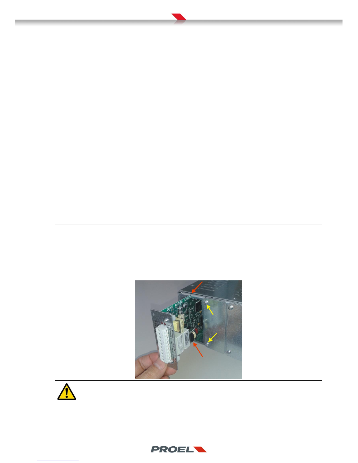
The installation of the modules inside the master and slave unit is very simple but requires some care when plugging the module in
the internal mainboard.
Remove the slot cover by unscrewing the screws pointed by the yellow arrows.
Slide the circuit of the module inside the dents pointed by the red arrows, then delicately push the module until the frame sets on
the unit’s back panel. Secure the module with the screws that were previously removed.
Installing the zone modules inside Master and Slave units
WARNING!! Do not force for any reason the unit inside the slot! Forcing the module may seriously damage the bus
connector inside the unit!
 Loading...