


PRE

PRE Preamplifier
PR O C E E D
WARNING: TO REDUCE THE RISK OF FIRE OR ELECTRIC SHOCK, DO
NOT EXPOSE THIS APPLIANCE TO RAIN OR MOISTURE.
CAUTION
RISK OF ELECTRIC SHOCK
DO NOT OPEN
CAUTION: TO REDUCE THE RISK OF ELECTRICAL SHOCK, DO
NOT REMOVE COVER. NO USER-SERVICEABLE PARTS INSIDE.
REFER SERVICING TO QUALIFIED PERSONNEL.
The lightning flash with arrowhead symbol, within an equilateral triangle, is intended
to alert the user to the presence of uninsulated “dangerous voltage” within the
product’s enclosure that may be of sufficient magnitude to constitute a risk of electric
shock to persons.
The exclamation point within an equilateral triangle is intended to alert the user to the
presence of important operating and maintenance (servicing) instructions in the literature
accompanying the appliance.
Marking by the “CE” symbol (shown left) indicates compliance of this device with the EMC
(Electromagnetic Compatibility) and LVD (Low Voltage Directive) standards of the
European Community.
NOTICE
This equipment has been tested and found to comply with the limits for a Class B digital device, pursuant to Part 15 of the
FCC Rules. These limits are designed to provide reasonable protection against harmful interference in a residential
installation. This equipment generates, uses and can radiate radio frequency energy and, if not installed and used in
accordance with the instructions, may cause harmful interference to radio communications. However, there is no guarantee
that interference will not occur in a particular installation. If this equipment does cause interference to radio or television
reception, which can be determined by turning the equipment on and off, the user is encouraged to try to correct the
interference by one or more of the following measures:
• Reorient or relocate the receiving antenna;
• Increase the separation between the equipment and the receiver;
• Connect the equipment into an outlet on a circuit different from that to which the receiver is connected;
• Consult the dealer or an experienced radio/TV technician for help.
CAUTION: Changes or modifications to this equipment not expressly approved by the manufacturer could void the user’s
authority to operate the equipment.
The information contained in the manual is subject to change without notice. The most current version of this manual will
be posted on our web site at http://www.madrigal.com.

Important Safety Instructions
Please read all instructions and precautions carefully and completely before operating your PRE preamplifier.
1. ALWAYS disconnect your entire system from the AC mains before connecting or disconnecting
any cables, or when cleaning any component.
2. This product is equipped with a three-conductor AC mains power cord which includes an
earth ground connection. To prevent shock hazard, all three connections must ALWAYS be
used. If your electrical outlets will not accept this type of plug, an adapter may be purchased.
If an adapter is necessary, be sure it is an approved type and is used properly, supplying an
earth ground. If you are not sure of the integrity of your home electrical system, contact a licensed electrician for assistance.
3. AC extension cords are not recommended for use with this product. If an extension cord must
be used, be sure it is an approved type and has sufficient current-carrying capacity to power
this product.
4. NEVER use flammable or combustible chemicals for cleaning audio components.
5. NEVER operate this product with any covers removed.
6. NEVER wet the inside of this product with any liquid.
7. NEVER pour or spill liquids directly onto this unit.
8. NEVER block air flow through ventilation slots or heatsinks.
9. NEVER bypass any fuse.
10. NEVER replace any fuse with a value or type other than those specified.
11. NEVER attempt to repair this product. If a problem occurs, contact your Proceed
12. NEVER expose this product to extremely high or low temperatures.
13. NEVER operate this product in an explosive atmosphere.
14. ALWAYS keep electrical equipment out of the reach of children.
15. ALWAYS unplug sensitive electronic equipment during lightning storms.
®
retailer.

From all of us at Madrigal Audio Laboratories, thank you for choosing the
Proceed PRE preamplifier.
A great deal of effort went into the design and construction of this precision
device. Used properly, it will give you many years of enjoyment.
4

Table of Contents
Unpacking and Placement ....................................................................... 7
Unpacking .......................................................................................................... 7
Installing Batteries in
the Remote Control ........................................................................................... 7
Placement .......................................................................................................... 7
Ventilation ........................................................................................................... 7
Operating Voltage...................................................................................... 8
PRE bottom-panel label ............................................................................ 8
Front Panel ................................................................................................... 9
........................................................................................................................... 11
Rear Panel ................................................................................................. 12
IR input tip polarity .................................................................................... 15
Using the PRE ............................................................................................. 17
Listening & Recording ..................................................................................... 17
Setting the Mute Level .................................................................................... 17
Setting Input Offsets ........................................................................................ 18
Learning Remote Control ......................................................................... 19
installing batteries in
the remote control .......................................................................................... 19
Programming and Using the Remote Control ........................................ 22
pre-programmed functions............................................................................ 22
learning set-up ................................................................................................. 22
learning new functions on the main keypad ........................................ 23
learning new functions
on device buttons .................................................................................... 24
erasing learned functions ........................................................................ 25
operation .......................................................................................................... 25
device buttons .......................................................................................... 26
main device mode .................................................................................. 26
automatic audio mode ........................................................................... 26
Planning Your Remote Control ................................................................ 27
remote control
function worksheet .......................................................................................... 27
remote control
function reference .......................................................................................... 28
(more on next page)
5

Remote Control
Advanced Features .................................................................................. 30
punch-throughs ............................................................................................... 30
volume control
“punch-through” ...................................................................................... 30
channel control
“punch-through” ...................................................................................... 31
transport control
“punch-through” ...................................................................................... 31
memory buttons .............................................................................................. 32
programming
memory buttons ....................................................................................... 33
erasing memory buttons .......................................................................... 34
changing the lcd display ................................................................................ 34
Teaching PRE Functions
to its Remote Control ...................................................................................... 35
Teaching PRE Front
Panel Commands ............................................................................................ 35
Teaching Other
PRE Commands ............................................................................................... 36
special commands table ........................................................................ 37
Using Surround
Sound Processors ...................................................................................... 39
Surround processors should
not come after the preamp........................................................................... 39
Surround processors should
not come before the preamp ....................................................................... 39
Surround processors should
not be in a tape loop ...................................................................................... 39
Surround sound and the PRE .......................................................................... 40
Noise in A/V systems ........................................................................................ 41
Care & Maintenance................................................................................ 42
U.S. and Canadian Warranty ................................................................... 43
90-Day Limited Warranty................................................................................. 43
Five Year Extended Warranty ......................................................................... 43
Obtaining Service ..................................................................................... 44
Specifications ............................................................................................ 45
Dimensions ................................................................................................ 46
6

Unpacking and Placement
Unpacking Unpack your Proceed
Installing Batteries in
the Remote Control
®
PRE preamplifier and keep all packing materials for
future transport. Locate and remove all accessory items from the cartons.
Accessories include:
1 AC power cord
1 PRE remote control
4 alkaline batteries for the remote control
1 hex (“Allen”) wrench
Carefully inspect the product for damage and flaws. If you discover any, see
your Proceed dealer immediately.
Turn the remote control over and slide the battery compartment cover up and
away from the body of the remote. Insert the four alkaline batteries found in
the Accessories kit, being careful to follow the polarity indications given on
the inside of the battery compartment. Replace the battery cover.
Batteries are more likely to leak corrosive chemicals when they are fully discharged. It is a good idea to check the batteries on this and all other remote
controls periodically, replacing those that are significantly weakened before
they actually fail completely.
The remote control included with your PRE includes a lithium cell to retain the
memory of learned commands even while you are changing the AA batteries.
This lithium cell must only be replaced by a qualified dealer who can dispose
of the lithium cell properly.
Caution: There is a danger of explosion if the lithium battery is
incorrectly replaced. Replace only with the same or
equivalent type recommended by the manufacturer.
Discard used batteries according to the manufacturer’s
instructions.
Placement Place the PRE near the source equipment, thus keeping interconnecting cables
reasonably short. It may be placed on a shelf or in a cabinet where it’s convenient to operate.
Note that adequate clearance for the AC cord and connecting
cables must be left behind the PRE. We suggest leaving at least
three inches of free space behind the PRE to allow all cables
sufficient room to bend without crimping or undue strain.
Ventilation Be sure to allow 2 to 3 inches of clearance above the PRE to allow heat dissi-
pation through air circulation.
7

PRE bottom-panel label
Operating Voltage
The PRE preamplifier is factory-set for 100V, 120V, 220V, or 240V AC mains
operation at either 50 or 60Hz, according to the country for which the unit
was manufactured. (230V/50Hz only in European Union countries, in compli-
ance with CE regulations.) Make sure that the label on the rear panel of the
PRE indicates the correct AC operating voltage for your location. The operating voltage cannot be changed by the user, and any attempt to do so will void
the warranty.
If the voltage indicated is incorrect relative to that supplied in your area, see
your Proceed dealer.
WARNING: BEFORE ATTEMPTING TO OPERATE THIS DEVICE,
REFER TO OWNER’S MANUAL FOR PROPER OPERATING
INSTRUCTIONS AND SAFETY PRECAUTIONS. HAZARDOUS
VOLTAGE AVAILABLE INSIDE; DISCONNECT AC – MAINS
CABLE BEFORE OPENING UNIT.
R
PR O C E E D
MADRIGAL AUDIO LABORATORIES, INC.
designed and manufactured in USA
For service, contact Madrigal Audio Laboratories or an Authorized
Dealer. Any modification to this equipment will void all warranties.
No User Serviceable Components Inside.
pre
S/N
8
1 2 3 4 5
pre
cd 1 cd 2 tape 1 tape 2/ssp bal/aux tuner
mute
bal
power
PR O C E E D
path
main
record
inverted polarity mono
678910
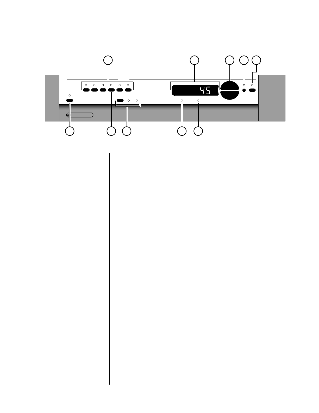
Front Panel
1 SOURCE SELECTION BUTTONS
These six buttons select audio signals from among the six audio inputs.
(Note that both cd1 and bal/aux are balanced inputs which use precision XLR connectors.) To use these selection buttons, choose the appropriate path (see path, below), and then make your selection.
2 MAIN DISPLAY
The main display provides information pertaining to the operation of the
PRE including relative volume levels, and is used in conjunction with the
buttons which surround it. At all volumes above a relatively quiet background level, and in all modes, the volume control enjoys a resolution of
0.5 dB. Thus a change of 10 decibels would be indicated by a change of
20 in the display.
The main display indicates the volume by default. In addition, it can also
display the balance. Right- and left-facing arrows are provided to indicate the direction of the balance offset, which is implemented in the
same 0.5 dB steps as the volume. Finally, the infrared receiver and transmitter for the remote control are positioned on the left side and center of
the main display, respectively.
3 VOLUME +/–
These up/down buttons are used to make adjustments on the PRE, apart
from source and path selection. While the volume +/– buttons normally
control the volume of the music system (main path), they can be used in
concert with other buttons to control several aspects of system performance (as indicated below).
9

4 BAL (BALANCE)
Pressing this button followed by the volume +/– buttons will alter the
relative volume of the Left and Right speakers. The direction of the
balance shift is indicated by the green arrowhead indicators in the main
display, and the magnitude of the balance shift is shown in the main display. Both the volume +/– buttons and the main display will revert to
their normal operation (volume) after a few seconds.
5 MUTE
Pressing the
mute button will reduce the main output level of the pream-
plifier by a user-modifiable amount, ranging from 1 to 56 decibels (2 to
112 in the main display; the factory default is -20 decibels, which is -40
in the display). Pressing the mute button a second time without adjusting
the volume will return it to its previous setting. If you adjust the volume
with either the front panel buttons or the remote control while in the
mute mode, the preamplifier will adjust its volume from the muted vol-
ume and disengage the mute function. By so doing, the PRE avoids sud-
den, unexpected changes in volume. (See Using the PRE for information
on changing the factory default mute setting.)
6 MONO INDICATOR
This indicator LED will illuminate when the PRE is placed into mono
mode from its remote control. (Hint: set the balance by placing the PRE
into mono mode and then adjusting the balance to place the resultant
“center” image to be equidistant between your loudspeakers. This procedure will compensate for small differences in effective speaker sensitivity
and room placement inequalities, yielding the largest possible image
when you return to stereo operation by pressing the mono button on the
remote control again. There is no front panel button for the mono function.)
7 INVERTED POLARITY INDICATOR
This LED will illuminate to indicate that the polarity of the PRE has been
inverted. This inversion is accomplished by pressing the polarity button
on the remote control. Pressing the same button a second time restores
the normal, non-inverting operation of the PRE. There is no front panel
button for this operation, as the distinction is best heard from the listening position.
8 PATH SELECTOR
Pressing this button cycles among your various signal path options:
• main — this path determines which audio sources are sent to
the main outputs on the back of the PRE. Sources selected for
the main path are indicated in yellow on the front panel
LEDs.
• record — determines which audio sources are sent to the
PRE’s record output jacks. As a safety measure, the PRE will
prevent the selection of any recordable device as its own
source (to avoid feedback loops). If such a selection is attempted, the PRE will cause the appropriate LED to flash on
the front panel as a warning. The source selected for the
record path is indicated on the front panel in red LEDs.
10

9 TAPE2/SSP INPUT
The tape2/ssp input of the PRE is special in that it may be used as either
a normal tape input such as you might find on other preamplifiers, or as
a dedicated surround sound processor loop. (See Using Surround Sound
Processors for more information.)
10 POWER & POWER LED
Assuming that the PRE’s power cord is connected to AC power, pressing
this latching power button connects the PRE to the AC mains and turns
on the unit. When power is restored after an interruption, the PRE will
be ready to operate (that is, it won’t be in standby mode), after a few
moments’ delay to allow its circuits to stabilize.
Front panel standby While most people will toggle the PRE between standby and
operate from the included remote control, if you need to do
so when the remote control is not nearby, you can press and
hold the
While the PRE is in standby, the LED above the power button is red.
When the PRE is ready to operate (that is, when it is not in standby
mode), this LED is amber. Naturally, when AC power is off, the LED is
off.
“path”
button for a few seconds.
11
i n p u t s
tape2/
cd2 tuner tape1
LL
RR
PR O C E E D
ssp
R
p r e by MADRIGAL AUDIO LABORATORIES
RRLL
cd1 bal/aux
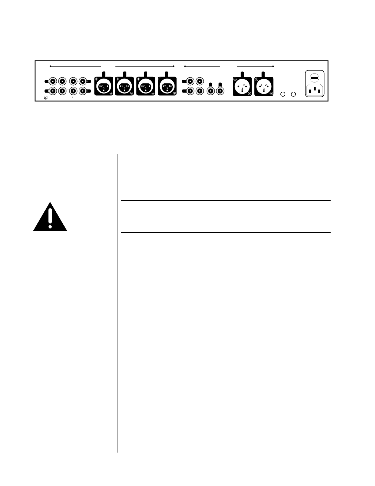
Rear Panel
Caution! Disconnect all associated equipment from the AC mains
~ ac mains
mains fuse:
.5A (250V) slo-blo 5x20mm
rec1 rec2/ssp
L
R
main out
R
o u t p u t s
L
main out
R
please see bottom panel for voltage and other information
L
remote
remote
IR
turn-on
BEFORE making any signal connections and applying power
to the PRE.
1 SINGLE-ENDED AUDIO INPUTS
Accepts right-channel and left-channel audio signals from source equipment with single-ended (RCA) outputs. Traditional single-ended audio
inputs are provided for a total of three components, designated: cd2,
tuner,
and tape1.
Connect the right-channel and left-channel single-ended outputs of your
various source components to the corresponding inputs on the PRE.
2 TAPE2/SSP INPUT
This single-ended audio input may be used either as a conventional input for a second tape deck or as a dedicated surround sound processor
loop. In the latter case, the front left and right outputs of your surround
sound processor would be routed to the tape2/ssp input and passed
through the PRE at unity gain (that is, with no change in volume), regardless of the volume control setting of the PRE.
The ssp function gives the outboard surround sound processor control
over the volume of all the loudspeakers (including those normally controlled by the PRE) when it needs that control. Returning the system to
two-channel stereo operation is then as simple as selecting a different
input. (See “Using Surround Sound Processors” for more information.)
12
To choose between either the standard tape2 input function or the spe-
cial ssp input (which operates at unity gain), press and hold the
tape2/ssp button until its LED indicator changes color. Amber (matching
the other input LEDs) indicates normal tape2 functionality; green indicates the special ssp mode of operation. (Again, see “Using Surround
Sound Processors” for more information.)
3 BALANCED AUDIO INPUTS
Accepts right-channel and left-channel signals from source equipment
with balanced outputs. Provisions are made for two balanced signals via
high quality XLR connectors, designated
cd1 and bal/aux.
The pin assignments of these XLR-type female input connectors are:
Pin 1: Signal ground
21
3
Pin 2: Signal + (non-inverting)
Pin 3: Signal – (inverting)
Connector ground lug: chassis ground
These pin assignments are consistent with the standards recently adopted
by the Audio Engineering Society. Refer to the operating manuals of your
balanced-output line-level sources to verify that the pin assignments of
their output connectors correspond to the PRE. If not, wire the cables so
that the appropriate output pin connects to the equivalent input pin.
Connect the right-channel and left-channel balanced outputs of your
source components to the corresponding balanced inputs on the PRE.
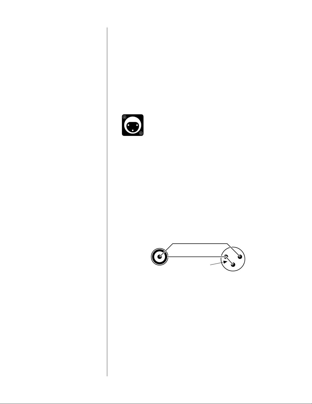
Note: If you do not have balanced sources and need more single-
ended inputs, it is possible to fabricate a cable to connect
line-level sources with single-ended output to these balanced
inputs:
1
2
22-gauge
3
buss wire
Male RCA
(connect to source)
Male XLR
(connect to PAV)
If you need them, your Proceed dealer can help you with these cables.
4 REC1 OUTPUT
These single-ended connections are used to provide a stereo signal to
the recording device which is connected to the tape1 input. Examples of
possible recording devices include a cassette deck, DAT, DCC, CD-R, or
Mini-Disc. Connect this output to the record input (sometimes also called
“line input” or simply “in”) of your recording device.
13

The PRE incorporates a safety feature which prevents selecting the same
device as both the source to be recorded and the source to be monitored
at the same time. Were you to do so, a feedback loop would be created
which could be potentially damaging to your loudspeakers. If you attempt to select the same source for both recording and monitoring, the
second selection will be refused and the indicator light will blink several
times before reverting to the previously-selected input.
5 REC2/SSP OUTPUT
The
rec2/ssp output may be used in conjunction with a second record-
ing device or with a surround sound processor.
When used with a second recorder, connect this output to the record input (sometimes also called “line input” or simply “in”) of your recording
device. Under these circumstances, the rec2/ssp outputs will function
exactly as the rec1 outputs do. (See rec1 output, above.)
When used with a surround sound processor, connect this output to an
audio input on your processor. The source selected to be “recorded” on
the PRE will then be made available to your surround sound processor
for whatever hall effects or other signal processing you might desire.
Monitor the tape2/ssp input on the PRE to allow the front left and right
channels to be passed along to the appropriate power amplifiers and
speakers. (See “Using Surround Sound Processors” for more information.)
6 SINGLE-ENDED MAIN OUTPUTS
Single-ended (“unbalanced”) outputs are provided for compatibility with
a wide range of associated components, including power amplifiers and
electronic crossovers.
If you use the single-ended outputs, connect them to the corresponding
inputs of your power amplifier (or other device). Note that special features of the PRE enable it to be used optimally with a surround sound
processor as one of its inputs. We do not recommend having a surround
sound processor follow the PRE in the signal path. (For more information, see “Using Surround Sound Processors.”)
If you elect to use single-ended connection between your PRE and your
power amplifiers, connect the right-channel and left-channel singleended main out RCAs of the PRE to the appropriate balanced inputs of
the power amplifier.
7 BALANCED MAIN OUTPUTS
If your power amplifier is equipped with balanced (sometimes called
“differential”) inputs, it is best to use these balanced outputs on your
PRE. A balanced signal from preamplifier to power amplifier will offer
the highest possible performance with the best immunity from commonmode noise, such as radio frequency interference (RFI). The balanced
output signal is made available by way of precision male XLR connectors
(requiring female XLRs on the preamplifier end of the interconnecting
cable).
14

The pin assignments of these XLR-type male outputs are:
Pin 1: Signal ground
12
3
Pin 2: Signal + (non-inverting)
Pin 3: Signal – (inverting)
Connector ground lug: chassis ground
Refer to your power amplifier’s operating manual to verify that the pin
assignments of its input connectors correspond to the PRE. If not, wire
the cable so that the appropriate output pin connects to the equivalent
input pin.
IR input tip polarity
Connect the right-channel and left-channel balanced
main outputs of the
PRE to the appropriate balanced inputs of the power amplifier.
8 REMOTE IR
A 1⁄8" “mini” jack in the lower right corner of the rear panel provides direct access to the infrared control circuitry of the PRE. This remote IR repeater input facilitates a wide range of installation options. If desired, the
PRE may be placed inside a cabinet or outside the normal line-of-sight in
the listening area, with the controlling IR signal being relayed to the PRE
by any of a number of commercially-available IR repeaters.
The incoming signal for the remote IR input should conform to widelyaccepted IR repeater standards: that is, the signal present should be between 3-12 volts DC at less than 100 mA current, with a positive tip polarity, as shown below:
+–
3-12 volts @ less
than 100 mA
Your Proceed dealer can help you take advantage of these design features to maximize your system’s versatility.
9 REMOTE TURN-ON
The PRE can control the status of certain compatible Madrigal power amplifiers, such as the Proceed AMP2. If this is desired, connect the remote
turn-on
output of the PRE to the remote turn-on input of those amplifiers
using a wire terminated with a 1⁄8" “mini” plug at both ends (available in
various lengths at electronics supply stores such as Radio Shack, or may
be custom made to length by your installing dealer). If more than one
Proceed amplifier is being used, simple “Y-adapters” may be used to
daisy-chain the turn-on signal for up to three AMPs turn-on inputs of
which are wired in parallel. The power amplifiers will then be turned on
when the PRE is on and placed in standby when the PRE is placed in
standby.
Note:the remote turn-on output provides a 300 msec long, 8 volt
positive pulse whenever the PRE turns on, and a 600 msec
long, 8 volt positive pulse whenever the PRE turns off. (This
information is sometimes needed in complex custom installations, and is provided for the designer/installer.)
15
 Loading...