


E D
PR O C E
Digital Surround Decoder

WARNING: TO REDUCE THE RISK OF FIRE OR ELECTRIC SHOCK, DO
NOT EXPOSE THIS APPLIANCE TO RAIN OR MOISTURE.
CAUTION
RISK OF ELECTRIC SHOCK
DO NOT OPEN
CAUTION: TO REDUCE THE RISK OF ELECTRICAL SHOCK, DO
NOT REMOVE COVER. NO USER-SERVICEABLE PARTS INSIDE.
REFER SERVICING TO QUALIFIED PERSONNEL.
The lightning flash with arrowhead symbol, within an equilateral triangle, is intended to alert the user to the presence of uninsulated “dangerous voltage” within the product’s enclosure that may be of sufficient magnitude to constitute a risk of electric shock to persons.
The exclamation point within an equilateral triangle is intended to alert the user to the presence of important operating and maintenance (servicing) instructions in the literature accompanying the appliance.
Marking by the “CE” symbol (shown left) indicates compliance of this device with the EMC (Electromagnetic Compatibility) and LVD (Low Voltage Directive) standards of the European Community.
NOTICE
This equipment has been tested and found to comply with the limits for a Class B digital device, pursuant to Part 15 of the FCC Rules. These limits are designed to provide reasonable protection against harmful interference in a residential installation. This equipment generates, uses and can radiate radio frequency energy and, if not installed and used in accordance with the instructions, may cause harmful interference to radio communications. However, there is no guarantee that interference will not occur in a particular installation. If this equipment does cause interference to radio or television reception, which can be determined by turning the equipment on and off, the user is encouraged to try to correct the interference by one or more of the following measures:
•Reorient or relocate the receiving antenna;
•Increase the separation between the equipment and the receiver;
•Connect the equipment into an outlet on a circuit different from that to which the receiver is connected;
•Consult the dealer or an experienced radio/TV technician for help.
CAUTION: Changes or modifications to this equipment not expressly approved by the manufacturer could void the user’s authority to operate the equipment.
The information contained in the manual is subject to change without notice. The most current version of this manual will be posted on our web site at http://www.madrigal.com.

Important Safety Instructions
Please read all instructions and precautions carefully and completely before operating your Proceed component.
1.ALWAYS disconnect your entire system from the AC mains before connecting or disconnecting any cables, or when cleaning any component.
2.This product is equipped with a three-conductor AC mains power cord which includes an earth ground connection. To prevent shock hazard, all three connections must ALWAYS be used. If your electrical outlets will not accept this type of plug, an adapter may be purchased. If an adapter is necessary, be sure it is an approved type and is used properly, supplying an earth ground. If you are not sure of the integrity of your home electrical system, contact a licensed electrician for assistance.
3.ALWAYS keep electrical equipment out of the reach of children.
4.AC extension cords are not recommended for use with this product. If an extension cord must be used, be sure it is an approved type and has sufficient current-carrying capacity to power this product.
5.NEVER use flammable or combustible chemicals for cleaning audio components.
6.NEVER operate this product with any covers removed.
7.NEVER wet the inside of this product with any liquid.
8.NEVER pour or spill liquids directly onto this unit.
9.NEVER block air flow through ventilation slots or heatsinks.
10.NEVER bypass any fuse.
11.NEVER replace any fuse with a value or type other than those specified.
12.NEVER attempt to repair this product. If a problem occurs, contact your Proceed® dealer.
13.NEVER expose this product to extremely high or low temperatures.
14.NEVER operate this product in an explosive atmosphere.
15.ALWAYS unplug sensitive electronic equipment during lightning storms.

Table of Contents
Maximizing the Value of Your Purchase ..................................................... |
7 |
send in that warranty card! ............................................................................... |
7 |
Unpacking and Placement ........................................................................ |
8 |
unpacking the digital surround decoder ......................................................... |
8 |
re-labeling your PAV remote control .................................................................. |
8 |
placement .......................................................................................................... |
9 |
ventilation ............................................................................................................ |
9 |
serial number label ..................................................................................... |
9 |
update you PAV software .................................................................................. |
9 |
register your purchase! ....................................................................................... |
9 |
Operating Voltage & Frequency ............................................................... |
10 |
warm up/break-in period ................................................................................ |
10 |
A Word About Installation .......................................................................... |
11 |
A Quick Start For CD .................................................................................. |
12 |
A Quick Start For Laserdisc ........................................................................ |
13 |
Special Design Features ........................................................................... |
14 |
hardware upgradable ..................................................................................... |
14 |
software updatable ......................................................................................... |
14 |
multichannel ..................................................................................................... |
14 |
audio computer ............................................................................................... |
15 |
Front Panel .................................................................................................. |
16 |
Rear Panel .................................................................................................. |
18 |
ac power cord polarity ............................................................................ |
19 |
Learning Remote Control .......................................................................... |
26 |
installing batteries in the remote control ......................................................... |
26 |
Using The Menu System ............................................................................ |
32 |
to enter the menu system ................................................................................ |
32 |
to exit the menu system ................................................................................... |
33 |
to select a menu item ...................................................................................... |
33 |
to change a menu item .................................................................................. |
33 |
to save changes ............................................................................................... |
33 |
to “escape” or “cancel” without saving any changes .................................. |
33 |
front panel equivalents .................................................................................... |
33 |
The Operate Menu .................................................................................... |
34 |
display position ................................................................................................. |
34 |
status preferences ............................................................................................. |
34 |
display timeout ................................................................................................. |
35 |
display of text .................................................................................................... |
35 |
display background ......................................................................................... |
35 |
volume display ................................................................................................. |
35 |
volume speed .................................................................................................. |
36 |
volume mute level ............................................................................................ |
36 |
maximum volume ............................................................................................ |
36 |
dialog normalization ........................................................................................ |
36 |
auto migration .................................................................................................. |
36 |
forced/manual migration ......................................................................... |
36 |
setup: locked/unlocked .................................................................................. |
36 |
The Setup Menu ......................................................................................... |
38 |
set source buttons ............................................................................................ |
39 |
example: setting up a cd transport ................................................................ |
39 |
(continued next page)
4

renaming source buttons ................................................................................. |
40 |
defining the input type .................................................................................... |
40 |
choosing a surround mode .............................................................................. |
41 |
is it a recording device? ................................................................................... |
41 |
how many input connectors? ......................................................................... |
42 |
defining input connectors ............................................................................... |
42 |
example: setting up a laserdisc player .......................................................... |
43 |
defining the video connection ....................................................................... |
44 |
defining multiple audio connections ............................................................. |
44 |
set speakers ...................................................................................................... |
46 |
set configuration ............................................................................................... |
47 |
set configuration menu ............................................................................ |
47 |
set distance ....................................................................................................... |
48 |
set distance menu .................................................................................... |
48 |
set levels ............................................................................................................ |
49 |
set levels menu .......................................................................................... |
50 |
bass level manager ......................................................................................... |
50 |
mode defaults ................................................................................................... |
51 |
before you use mode defaults ................................................................. |
52 |
The Custom Menu ..................................................................................... |
55 |
teach IR commands to your remote ............................................................... |
56 |
remote only menu ..................................................................................... |
57 |
surround, path and misc control menus .................................................. |
57 |
control trigger 1 menu ...................................................................................... |
58 |
control trigger 2 menu ..................................................................................... |
59 |
rear ir input menu ............................................................................................. |
59 |
changing the pav’s ir address ......................................................................... |
60 |
The About… Menu ..................................................................................... |
61 |
Planning Your Installation .......................................................................... |
62 |
choosing the equipment ................................................................................. |
62 |
planning your equipment placement ............................................................ |
62 |
the “correct” size for your television screen .................................................... |
63 |
the power amplifiers ........................................................................................ |
63 |
the left, center and right (LCR) front speakers ................................................ |
63 |
toe-in of left & right speakers ................................................................... |
64 |
the subwoofer(s) ............................................................................................... |
64 |
the surround speakers ...................................................................................... |
64 |
dipolar surround placement .................................................................... |
65 |
conventional surround placement .......................................................... |
65 |
working in unusually large rooms .................................................................... |
65 |
System Planning Guide ............................................................................. |
66 |
video placement ............................................................................................. |
66 |
electronics placement ..................................................................................... |
66 |
speaker placement ......................................................................................... |
66 |
additional notes on speaker placement ........................................................ |
67 |
Using PAV/PDSD ......................................................................................... |
68 |
setting the volume ............................................................................................ |
68 |
home thx cinema® .......................................................................................... |
68 |
dolby pro logic surround .................................................................................. |
69 |
stereo surround ................................................................................................. |
69 |
mono surround ................................................................................................. |
69 |
surround off ....................................................................................................... |
69 |
mono ................................................................................................................. |
69 |
automatic migration ........................................................................................ |
70 |
forced/manual migration ................................................................................ |
70 |
watching a simulcast ....................................................................................... |
70 |
(continued next page)
5

Programming the Remote Control ............................................................ |
71 |
programming other components’ functions .................................................. |
71 |
teaching the PAV remote control new commands ................................ |
72 |
Planning Your Remote Control .................................................................. |
73 |
the proceed bank: left .................................................................................... |
73 |
the proceed bank: center .............................................................................. |
73 |
the proceed bank: right .................................................................................. |
73 |
bank 2: left ........................................................................................................ |
74 |
bank 2: center .................................................................................................. |
74 |
bank 2: right ...................................................................................................... |
74 |
Your System Settings .................................................................................. |
75 |
operate menu settings ..................................................................................... |
75 |
cd 1 button defaults ......................................................................................... |
75 |
cd 2 button defaults ......................................................................................... |
75 |
tape 1 button defaults ...................................................................................... |
76 |
tape 2 button defaults ..................................................................................... |
76 |
bal/aux button defaults ................................................................................... |
76 |
tuner button defaults ........................................................................................ |
76 |
vcr 1 button defaults ......................................................................................... |
77 |
vcr 2 button defaults ........................................................................................ |
77 |
laserdisc button defaults .................................................................................. |
77 |
tv/aux button defaults ..................................................................................... |
77 |
low freq cutoff settings ..................................................................................... |
78 |
set distance ....................................................................................................... |
78 |
set levels ............................................................................................................ |
78 |
bass level manager ......................................................................................... |
78 |
mode defaults: discrete ................................................................................... |
78 |
mode defaults: pro logic ................................................................................. |
78 |
mode defaults: stereo surround ...................................................................... |
78 |
mode defaults: mono surround ...................................................................... |
78 |
mode defaults: surround off ............................................................................ |
79 |
mode defaults: mono ...................................................................................... |
79 |
control trigger 1 ................................................................................................. |
79 |
control trigger 2 ................................................................................................ |
79 |
rear ir in .............................................................................................................. |
79 |
ir address ........................................................................................................... |
79 |
Room Acoustics ......................................................................................... |
80 |
room reverberation .......................................................................................... |
80 |
the boundary effect ........................................................................................ |
80 |
room modes ...................................................................................................... |
81 |
Troubleshooting ......................................................................................... |
82 |
Care and Maintenance ............................................................................ |
84 |
U.S. and Canadian Warranty .................................................................... |
85 |
90-day limited warranty ................................................................................... |
85 |
five year extended warranty ........................................................................... |
85 |
Obtaining Service ..................................................................................... |
86 |
Specifications ............................................................................................ |
87 |
Dimensions ................................................................................................ |
88 |
Installation Notes ....................................................................................... |
89 |
Proceed PAV/PDSD System Quick Start… ................................................ |
90 |
6

Maximizing the Value
of Your Purchase
Congratulations on choosing a superb product. Your Proceed Digital Surround Decoder (PDSD) is designed to give you many years of outstanding performance, and we are confident you will be happy with it.
We value our relationship with our customers, and often are in a position to help you enjoy your home entertainment system even more—if we have some way of contacting you.
send in that warranty card! Sending in your warranty card registers your product with us so that warranty service in the U.S. and Canada can be obtained easily and quickly even if you have lost your original sales slip. (And how many of us are organized enough to retain all those sales slips?) Moreover, for customers in the U.S. and Canada, sending in the card automatically extends the warranty from 90 days to five years, at no cost to you. (See the warranty policy near the end of this manual.) Please send it in soon, before you forget.
But there are even more benefits to sending in your registration card:
software update notices
performance upgrade notices
We occasionally offer software updates to our products, providing new features and control options. In the case of the Digital Surround Decoder, these updates are easily done without even opening up the unit, via flash-memory. If they include features you would like to have, you can get them—if you know about them.
We also try to offer hardware-oriented performance upgrades and/or conversions to make upgrading within a family of products as cost-effective as possible for our customers. With the extraordinary modularity of the Digital Surround Decoder, these upgrade modules are particularly easy to install and use. While not all upgrades can be inexpensive, we work to ensure that they all represent excellent values—if you know about them.
So please, take a few minutes to fill out the warranty registration card, and drop it in the mail.
7

unpacking the |
|
|
Unpacking and Placement |
|
|||
|
|
Unpack your Digital Surround Decoder and remove all accessories from the car- |
|
digital surround decoder |
|
|
ton. |
|
|
|
|
Important! |
|
|
Keep all packing materials for future transport of your Digital |
|
|
|
Surround Decoder. Shipping your new component in anything |
|
|
|
other than its purpose-designed packing material may result |
|
|
|
in damage that is not covered by the warranty. |
your new system |
|
|
|
|
|
The PAV/PDSD system uses a learning remote control that includes many new |
|
remote control |
|
|
features and capabilities. Of course, it already has all o fthe codes it needs for |
|
|
|
controlling your PAV/PDSD combination, built in. However, you can teach it addi- |
|
|
|
tional commands as well. In many cases everything in your system can be run |
|
|
|
from this one remote control. |
|
|
|
|
Caution: |
|
|
Your Proceed remote control also contains a lithium battery |
|
|
|
that maintains its memory in the absence of the alkaline |
|
|
|
batteries. |
|
|
|
Installing a replacement lithium battery incorrectly may result |
|
|
|
in damage to the remote control and/or explosion of the |
|
|
|
battery. We recommend this be performed by the dealer. |
|
|
|
This lithium battery must be replaced only with the same or |
|
|
|
equivalent type, and must be installed properly. Discard used |
|
|
|
batteries according to the battery manufacturer’s instructions. |
placement |
|
|
|
|
|
Place the Digital Surround Decoder near the sources, thus keeping interconnect- |
|
|
|
|
ing cables reasonably short. It may be placed on a shelf or in a cabinet where it’s |
|
|
|
convenient to operate. |
|
|
|
Note that adequate clearance for the AC cord and connecting |
|
|
|
cables must be left behind the Digital Surround Decoder. We suggest |
|
|
|
leaving at least three inches of free space behind the Digital |
|
|
|
Surround Decoder to allow all cables sufficient room to bend |
|
|
|
without crimping or undue strain. |
ventilation |
|
|
It is normal for your Digital Surround Decoder to run quite warm. Be sure to al- |
|
|
|
low 2 to 3 inches of clearance above it to allow heat dissipation through air circu- |
|
|
|
lation. The vents on both the bottom and the top of the Digital Surround De- |
|
|
|
|
8

coder must be kept free from any obstruction which would reduce the flow of air through the unit. Avoid placement on soft surfaces that would restrict airflow (such as carpeting).
If your PDSD becomes too warm, it will display an on screen message to that effect. If the temperature continues to rise, the unit will eventually protect itself by shutting itself off. This eventuality is extremely unlikely unless its surrounding ambient temperature is uncomfortably hot for people (as well as electronics). An internal, temperature-controlled cooling fan kit may be ordered from Madrigal if you do see the on screen warnings about excessive temperatures, and if improving the available ventilation in the installation would be difficult. Contact your dealer or distributor for more information.
Drawings are included in this manual to facilitate special installations and custom cabinetry (see Dimensions).
The serial number for your Digital Surround Decoder is found on the bottom of the unit. Please note and record this number for your future reference.
serial number label
WARNING: BEFORE ATTEMPTING TO OPERATE THIS DEVICE, |
|
|||
REFER TO OWNER’S MANUAL FOR PROPER OPERATING |
R |
|||
INSTRUCTIONS AND SAFETY PRECAUTIONS. HAZARDOUS |
PR O C E E D |
|||
VOLTAGE AVAILABLE INSIDE; DISCONNECT AC – MAINS |
MADRIGAL AUDIO LABORATORIES, INC. |
|||
CABLE BEFORE OPENING UNIT. |
||||
|
|
|
designed and manufactured in USA |
|
|
|
|
Manufactured under license from Dolby Licensing Corporation. Additionally licensed |
|
No User Serviceable Components Inside. |
under one or more of the following patents: U.S. numbers 3,632,886, 3,746,792 |
|||
and 9,959,590; Canadian numbers 1,004,603 and 1,037,877. “Dolby”, “Pro Logic” |
||||
For service, contact Madrigal Audio Laboratories or an Authorized |
||||
and the double-D symbol are trademarks of Dolby Licensing Corporation. |
||||
Dealer. Any modification to this equipment will void all warranties. |
Manufactured under license from DTS Technology, LLC. The term DTS and the |
|||
|
|
|
||
digital surround decoder |
DTS logo are trademarks of DTS Technology, LLC. |
|||
Manufactured under license from Lucasfilm Ltd. Additionally licensed under the |
||||
|
|
|
||
S/N |
|
|
following patents: U.S. number 5,043,970; 5,189,703; and 5,222,059. Foreign |
|
|
|
patents pending. Lucasfilm THX Audio, Lucasfilm, and Home THX Cinema are |
||
|
|
|
registered trademarks of Lucasfilm Ltd. |
|
update you PAV software The PDSD is shipped with an EPROM for the PAV with which it will be used. This EPROM allows the two components to work together as a single system. It must be installed in your PAV by your dealer. Note that there are no user-ser- viceable parts inside either the PAV or the PDSD.
register your purchase! Having found the serial number, now would be a good time to fill out the registration card. Please register your purchase so we can advise you of software updates and other items of interest.
In the U.S. and Canada, registering your purchase also automatically extends your warranty from 90 days to five years. It will take only a minute or so. Please complete the card now, before you forget.
9

|
|
Operating Voltage |
|
||
|
|
& Frequency |
|
|
The Digital Surround Decoder is set at the factory (internally) for 100V, 120V, |
|
|
220V, 230V, or 240V and either 50 or 60 Hz AC mains operation, as appropriate |
|
|
for the country in which it is to be sold. (230V/50Hz only in European Union |
|
|
countries, in compliance with CE regulations.) Neither the voltage nor the line |
|
|
frequency setting may be changed by the user. |
|
|
Make sure that the label on the rear panel of the Digital Surround Decoder |
|
|
(above the AC input receptacle) indicates the correct AC operating voltage for |
|
|
your location. Attempting to operate the Digital Surround Decoder at an incorrect |
|
|
voltage can damage the unit. |
|
|
|
Warning: |
|
Neither the voltage nor the line frequency settings of your |
|
|
Digital Surround Decoder may be changed by the user. There |
|
|
are no user-serviceable parts within the unit. Please refer any |
|
|
problems to an authorized Proceed service center. |
|
|
|
|
|
If the AC mains voltage or frequency indicated on your Digital Surround Decoder |
|
|
is incorrect, please contact your local, authorized Proceed dealer or distributor. |
|
|
The Digital Surround Decoder can easily be powered by a normal 15-ampere AC |
|
|
mains line. If other devices are also powered from the same AC line, their addi- |
|
|
tional power consumption should be taken into account. |
warm up/break-in period |
|
Although your Proceed Digital Surround Decoder delivers outstanding perfor- |
|
|
mance straight out of the box, you should expect to hear it continue to improve |
|
|
as it reaches its normal operating temperatures and its various components |
|
|
“break-in.” It has been our experience that the greatest changes occur within the |
|
|
first 300 hours as the PDSD reaches thermal equilibrium and the capacitors fully |
|
|
form. After this initial break-in period, the performance of your new product |
|
|
should remain quite consistent for years to come. |
|
|
The only exception to this rule is if power is removed from the unit for an ex- |
|
|
tended period of time, allowing it to cool down. Depending on the degree of |
|
|
cooling involved, you should expect a brief warm-up period before the Digital |
|
|
Surround Decoder’s sound quality is at its best. Unless your Digital Surround De- |
|
|
coder was allowed to become quite chilled, subsequent thermal re-stabilization |
|
|
should not take long. |
|
|
|
10
A Word About Installation
Every effort has been made to make the Proceed PAV/PDSD system simple and straightforward to install and use. Its flexibility allows it to solve problems that might otherwise compromise the performance of your system.
Unfortunately, we have no way to evaluate many other variables such as the size and shape of your room, its acoustics, and the associated equipment you have chosen to use with your PAV/PDSD. All of these factors influence the ultimate performance of your system. Moreover, the PAV/PDSD incorporates many systemspecific adjustments which enhance its performance with the widest possible range of associated components.
For this reason, we strongly encourage you to have your system installed and calibrated by your dealer, whose experience, training, and specialized equipment can make a profound difference in the final performance of the system.
The PAV/PDSD features the ability to “remember” the carefully calibrated settings chosen by your installer. You may adjust any or all of these settings to suit your taste for a particular recording, either from the front panel or from the remote control. When you want to return to the calibrated settings (which most accurately reproduce the widest variety of program material), simply press recall on the remote control or on the front panel.
11

A Quick Start For CD
The PAV/PDSD is an exciting system, and we understand that many owners will be anxious to get it up and running as quickly as possible. What follows is not a replacement for a complete setup of the system. Rather, it is provided so you can get some music playing from a single digital source as quickly as possible. It assumes that your system is already set up in other respects (speakers connected to power amps, etc.). Once done, please read up on how to do a complete setup and calibration in order to get the most from your investment (or have your dealer/installer do it for you).
1MAKE THE PHYSICAL CONNECTIONS; TURN EVERYTHING ON
Connect the Communications Cable between the PAV and the PDSD; connect the outputs of the PDSD to your power amplifiers, as indicated (front, rear, center, sub); connect a CD transport to any matching digital input connector on the PDSD, noting which connector you use; ensure that the main video output of the PAV is connected to your television (so you can see the on screen menus). Once this is done, turn on all the components involved (CD transport, PAV, PDSD, television, amplifiers). Turn the amps on last (always a good habit with any audio system).
2PRESS AND HOLD THE CD1 BUTTON ON THE FRONT OF THE PAV
This shortcut of pressing and holding an input button will take you directly to the define button menu for that button.
3TELL THE SYSTEM WHICH CONNECTOR YOU USED FOR YOUR CD TRANSPORT IN STEP 1
We have no way of knowing what sort of digital interface your particular CD transport might use (AES/EBU? RCA? BNC? EIA-J?), but logically, you’d like to be able to use your main CD player with the button labeled cd1. This step allows you to use whatever connector you need to use in conjunction with the button you’d like to use. Using the volume +/– buttons, move the arrow cursor down to the line that defines your first audio connection (1: Digital, Dig 1) and press enter. Then move the arrow cursor down (volume +/–) to the line that defines which connector is being used, and press enter again. With the cursor changed to an x instead of an arrow, the volume +/– buttons will allow you to select whatever digital input connector you used in Step 1. When done, press enter again to save your change.
4PRESS MENU TO EXIT THE MENU SYSTEM, AND ENJOY
Make sure the volume is on at a low level before you fire up your CD player, press the cd1 button, and raise the volume to a comfortable level. According to the factory defaults (which you can easily change), cd1 is preset to come on in 2-channel/surround off. You should properly calibrate the system so all speakers are playing at the proper volumes before you listen critically to multichannel audio. Performing this calibration only takes only a few more minutes, but you should read up on it a bit first. You can enjoy the PAV/PDSD system in regular stereo until then.
12

A Quick Start For Laserdisc
Okay, so now you have some music to listen to while reading the manual. But you’re in a rush to hear Dolby Digital on your new system. Remember: What follows is not a replacement for a complete setup of the system. We will assume here that you have already done the CD setup on the previous page. To get a laserdisc player playing:
1MAKE THE PHYSICAL CONNECTIONS
If you have a Dolby Digital (AC-3) output on your laserdisc player and the RF Demodulator card in the PDSD, connect the AC-3 output to digital input 11 on the PDSD. Also connect the (normal) digital output of your LD to any matching digital input on the PDSD, noting which one you use. Connect the analog outputs of the LD to the laserdisc inputs of the PAV. Finally, don’t forget to connect the video output of your laserdisc player to the corresponding input on the PAV. Turn everything on.
2PRESS AND HOLD THE LASERDISC BUTTON ON THE PAV
This shortcut of pressing and holding an input button will take you directly to the Define Button menu for that button.
3TELL THE SYSTEM WHICH CONNECTORS YOU USED FOR YOUR LASERDISC PLAYER IN STEP 1
Using the volume +/– buttons, move the arrow cursor down to the line that defines your video connection and press enter. Confirm that the video is connected to the laserdisc connector, and whether you used composite or S-video connections. Press enter to save any changes you might need to make, and then press menu to return to the previous menu.
Similarly, set up all three audio connections: move the arrow cursor down (volume +/–) to the line that defines your first choice, and press enter again. With the cursor changed to an x instead of an arrow, the volume +/– buttons will allow you to select digital input 11 RF (for example). When done, press enter again to save your change, and move on to your second choice (a digital input); then your third choice (the analog connection), saving changes as you go.
This hierarchy allows the system to automatically select the best available signal, by associating up to three different connections with a single button on the front panel of the PAV.
4PRESS MENU TO EXIT THE MENU SYSTEM, AND ENJOY
Make sure the volume is on at a low level before you fire up your laserdisc player; press the laserdisc button once, and raise the volume to a moderate/ comfortable level. Important: you should properly calibrate the system so all speakers are playing at the proper volumes before you listen critically to multichannel audio. Performing this calibration only takes only a few more minutes, but you should read up on it first. Please review the chapter on The Setup Menu for more information, pp. 39-55.
13

Special Design Features
Congratulations on your purchase of the Proceed Digital Surround Decoder (PDSD). We have gone to great lengths to ensure that the PDSD remains “future-proof” even in these times of change. As a result, you will be able to enjoy the outstanding performance of the Digital Surround Decoder for many years. In case you are interested in technical details, what follows is a brief outline of some of the key technologies in your new product.
hardware upgradable The Digital Surround Decoder employs a ten slot backplane configuration. This means that various combinations of up to ten “cards” can be inserted into the back of the unit, and that they will all communicate with each other as needed without having to install jumpers or deal with point-to-point wiring. In fact, the Digital Surround Decoder is in many respects more “plug and play” than many computers that lay claim to the name.
The modularity of the Digital Surround Decoder ensures that the product can easily accommodate changes in the future that might require new hardware. For example, if the industry were to establish a new standard for digital interconnection, using a different physical connector, most products would be obsolete overnight; with the PDSD, you would merely slide a new module into a slot.
Mind you, we do not believe that you will have to change hardware anytime soon. We even went to the trouble of designing our own high bandwidth, programmable DIR (Digital Interface Receiver), the circuitry that actually receives a digital signal and determine “which bits go where.” We did this to ensure that the product you buy today can handle everything that a dedicated DVD-for-audio disc may offer in the future. You see, conventional DIRs cannot handle the full 10 Mb/sec data rate of DVD… but ours can. Moreover, our DIR actually reclocks the incoming digital signal to greatly reduce timing errors in the signal (jitter), making every source you connect to the Digital Surround Decoder sound better than it could otherwise.
software updatable All the software that the Digital Surround Decoder uses is stored in special “flash” memory that can easily be updated as improvements are made available. These improvements can affect both operational and performance enhancements.
For example, if a new, dedicated DVD-for-audio format is decided at some point, it may well have 24-bit, 96 kHz sampling rate data on it as well as traditional 16 bit, 44.1 kHz data (for backwards compatibility). With a simple software download a short time after such a standard is announced, your Digital Surround Decoder would be able to both decode and play back the new audio standard, and flip back and forth between the two versions of the music on the disc for comparison purposes.
The Digital Surround Decoder is designed to avoid the premature obsolescence that will be the hallmark of far too many products sold in these changing times.
multichannel The Digital Surround Decoder is designed to be flexible with respect to its audio configurations, as well. In its standard configuration, it provides the standard 5.1 channel selection of outputs made popular by home theater. However, it can
14

also be upgraded to an eight channel processor simply by inserting another card, whether to accommodate larger rooms or more sophisticated audio processing. It is just a matter of what you want the system to do. That way, you can have the system the way you want it to work, rather than the way we thought you’d want it to work. (After all, a no-compromise, high performance audio system should not be “one size fits all.”)
Moreover, the PDSD was designed from the outset to be a high end multichannel product. All channels use full 20-bit multibit D/A converters rather then the less costly single-bit converters (often called “Sigma-Delta” or Delta-Sigma” converters) commonly found in multichannel products. The PDSD uses thes more costly D/A converters for the simple reason that they sound better.
audio computer Conventional audio DSP design requires the addition of costly hardware every time you wish to add functionality. In these designs, Dolby Digital (AC-3) has its own, dedicated DSP chip and associated supporting circuitry; so does DTS; so does MPEG. Want a new feature? Buy more hardware.
This strikes us as ridiculous.
You would not buy a computer for writing, knowing that you would have to buy another computer for calculations, and another for graphics, and a fourth for database work. To do so would be enormously wasteful, as expensive microprocessors would sit idly while you were doing something else.
The same is true in “audio computers.”
The Digital Surround Decoder is the first of a new generation of power DSP (Digital Signal Processing) engines that can load software in and out of memory dynamically, as your computer does. Want to listen to a Dolby Digital soundtrack? The PDSD loads the appropriate software and runs it. Movie over, want to listen to CD? No problem. Oh, the CD is DTS-encoded? Still no problem — the DTS software is loaded and runs automatically.
Madrigal was an early partner of Motorola in developing the next generation of DSP chips, the 56300-series. Designed to replace the aging 5600X series, these new chips offer twice the performance and vastly more flexibility. With three such chips in each Digital Surround Decoder, we have the power to run any of these programs as well as our own proprietary digital filtering algorithms.
Why did we develop such advanced technology? Simple: better performance for today, and for tomorrow.
15

1 |
2 |
d i g i t a l s u r r o u n d d e c o d e r |
L U C A S F I L M |
|
|
|
® |
|
power |
digital processing |
|
P R O C E E D |
|
Front Panel
1DIGITAL PROCESSING LED
This digital processing LED is normally completely off when an analog source has been chosen, indicating that no digital signal processing is even being attempted.
If the PDSD cannot communicate with the PAV (due to a forgotten communications cable, for example), the digital processing LED will blink to indicate that it is trying (but not succeeding) to communicate with the PAV.
The digital processing LED glows red when a digital signal has been selected, but cannot be “locked” onto and used. (Example: the RF output of a laserdisc player typically goes “dead” during scanning, chapter searches, and side changes, interrupting the signal and preventing the Digital Surround Decoder from doing what you have “asked” it to do.)
Finally, the digital processing LED glows amber when a digital signal has both been chosen and is being successfully received, indicating that digital processing is possible.
The Digital Surround Decoder will automatically and transparently decode PCM (including a digital version of Dolby Pro Logic), Dolby Digital (formerly called AC-3), DTS Coherent Sound, and MPEG, switching to whatever form of digital decoding and processing the signal requires. In any of these cases, the digital processing LED will glow amber to indicate that the Digital Surround Decoder is handling the signal for you.
If you wish to learn which of these digital processes is active, press the status button on the remote control.
16

2POWER & POWER LED
Assuming that the Digital Surround Decoder’s power cord is connected to AC power, pressing this latching power button connects the PDSD to the AC mains and turns on the unit. When power is restored after an interruption, the PDSD will be ready to operate (that is, it won’t be in standby), after a few moments’ delay to allow its circuits to stabilize.
While the Digital Surround Decoder is in standby, the LED above the power button is red. When the Digital Surround Decoder is ready to operate (that is, when it is not in standby mode), this LED is amber. Naturally, when AC power is off, the LED is off.
17

1 |
2 |
3 |
4 |
5 |
6 |
7 |
8 |
9 |
10 |
11 |
120VAC60Hz ~
digital inputs
8
9
10 11
7 |
1 |
|
2 |
3 |
|
4 |
5 |
|
inputs |
6 |
|
digital |
||
1 |
||
|
3 |
|
|
2 |
digital |
|
|
out |
|
L |
output |
1 2 3 |
remote |
2 |
|
R |
|
3 |
|
1 |
pav pass-through
R  L
L
R  L
L
C  S
S
center/sub rear main surround
front output
R  L
L
L
1 2 3
R
1 2 3
 surround output
R  L
L
L
1 2 3
R
1 2 3
 center/sub output
C  S
S
S
1 2 3
C
1 2 3
comm. |
1 |
2 |
on/off |
|
rem |
|
control |
master slave |
|
(optional)
1 |
2 |
|
2 |
|
2 |
|
3 |
output |
1 |
1 |
|
aux. |
2 |
|
3 |
|
1 |
Rear Panel
Caution! |
Disconnect all associated equipment from the AC mains |
|
BEFORE making any signal connections and applying power |
|
to the Digital Surround Decoder. |
|
|
1AC MAINS INPUT
This input accepts AC power from the AC mains (via the supplied AC cable).
Warning! |
The Digital Surround Decoder is set internally for 100, 120, 220, |
|
230, or 240VAC mains operation at either 50 or 60Hz. Make |
|
sure that the label on the rear of the unit indicates the correct |
|
AC operating voltage and frequency for your location before |
|
connecting it to AC mains. |
|
|
|
Connect the female end of this cable to the Digital Surround Decoder. Con- |
|
nect the male end of this cable to wall outlet. |
18

ac power cord polarity |
To Digital Surround |
To AC mains |
|
Decoder |
|
|
|
|
|
|
|
|
|
|
|
|
|
|
|
|
|
|
|
|
|
|
|
|
1 |
= Line (hot) |
|
1 2 |
1 |
2 |
|
|
2 |
= Neutral |
||
|
|
|
|
|
|
3 |
= Earth ground |
|
3 |
|
3 |
|
|
|
|
|
|
The power consumption of the Digital Surround Decoder is only about 100 watts, about the same as a light bulb. As such most people will leave it on (or in standby) at all times. If you elect to turn the PDSD completely off (rather than in placing it in standby), we advise waiting at least five seconds between power cycles to allow the normal power-up sequence to complete without interruption.
2DIGITAL INPUTS 7-11
Please remember to make a note of what sources you connect to which
|
|
|
|
|
inputs. You will need to set up the relationships between front panel but- |
|
|
|
|
|
7 |
tons and rear panel connectors later, in the setup menu system. |
|
|
|
|
|
|
|
|
|
|
|
|
|
For now, you can connect any source to any compatible connector—just |
|
|
|
|
8 |
|
||
|
|
|
|
keep a list of what-goes-where. (Just such a list is waiting for you later in |
||
|
|
|
|
|
||
|
|
|
|
|
this manual. You might want to copy it in order to keep the original clean |
|
|
|
|
|
|
for future use.) |
|
inputs |
|
9 |
|
|
||
|
|
|
|
|||
|
|
|
|
|
|
|
digital |
10 |
11 |
|
Digital Input 7 accepts digital audio in the EIAJ optical (sometimes called |
||
|
disc, laserdisc, DVD or other digital source component. Connect the EIAJ |
|||||
|
|
|
|
|
“Toslink”) digital interface standard from a digital satellite receiver, compact |
|
|
|
|
|
|
digital output of your source component to the EIAJ input of the Digital Sur- |
|
|
|
|
|
|
round Decoder using a high quality EIAJ optical cable. |
|
|
|
|
|
|
Digital Inputs 8-9 accept digital audio conforming to the 75Ω |
S/PDIF digital |
|
|
|
|
|
||
|
|
|
|
|
interface standard (via 75Ω cables equipped with BNC-type connectors) |
|
|
|
|
|
|
from a digital satellite receiver, compact disc, laserdisc, DVD or other digital |
|
|
|
|
|
|
source component. Connect the 75Ω S/PDIF output of your source compo- |
|
|
|
|
|
|
nent to either of these inputs of the Digital Surround Decoder, using a high |
|
|
|
|
|
|
quality 75Ω cable such as Madrigal MDC-2. |
|
|
|
|
|
|
Digital Inputs 10-11 accept digital audio conforming to the 75Ω |
S/PDIF digital |
|
|
|
|
|
interface standard (via cables equipped with RCA-type connectors) from a |
|
|
|
|
|
|
digital satellite receiver, compact disc, laserdisc, DVD or other digital source |
|
|
|
|
|
|
component. Connect the 75Ω S/PDIF output of your source component to |
|
|
|
|
|
|
either of these inputs of the Digital Surround Decoder, using a high quality |
|
|
|
|
|
|
75Ω cable such as Madrigal MDC-2. |
|
|
|
|
|
|
If you have the optional internal RF demodulator installed in your Digital |
|
|
|
|
|
|
Surround Decoder, Digital Input 11 is dedicated to that RF connection and |
|
|
|
|
|
|
can only be used for that purpose. Connect the RF (Dolby Digital/AC-3) |
|
|
|
|
|
|
output from your laserdisc player to Digital Input 11 if you have the internal |
|
|
|
|
|
|
RF demodulator installed, using low-capacitance cable such as CZ Gel-2. |
|
19

1
|
2 |
3 |
inputs |
4 |
5 |
|
6 |
|
digital |
|
|
PUSH |
2 1 3 |
digital |
|
|
out |
|
L |
output |
1 2 3 |
remote |
2 |
|
R |
|
3 |
|
1 |
20
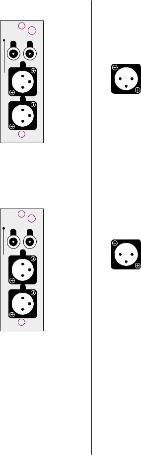
3DIGITAL INPUTS 1-6
Please remember to make a note of what sources you connect to which inputs. You will need to set up the relationships between front panel buttons and rear panel connectors later, in the setup menu system. For now, you can connect any source to any compatible connector—just keep a list of what-goes-where. (Just such a list is waiting for you later in this manual. You might want to copy it in order to keep the original clean for future use.)
Digital Input 1 accepts digital audio in the EIAJ optical (sometimes called “Toslink”) digital interface standard from a digital satellite receiver, compact disc, laserdisc, DVD or other digital source component. Connect the eiaj digital output of your source component to the EIAJ input of the Digital Surround Decoder using a high quality EIAJ optical cable.
Digital Inputs 2-5 accept digital audio conforming to the 75Ω S/PDIF digital interface standard (via cables equipped with RCA-type connectors) from a digital satellite receiver, compact disc, laserdisc, DVD or other digital source component. Connect the 75Ω S/PDIF output of your source component to either of these inputs of the Digital Surround Decoder, using a high quality 75Ω cable such as Madrigal MDC-2.
Digital Input 6 accepts digital audio in the professional 110Ω AES/EBU digital interface standard (via a cable equipped with XLR-type connectors) from a digital satellite receiver, compact disc, laserdisc, DVD or other digital source component. Connect the AES/EBU digital output of your source component to the AES/EBU input of the PDSD using a high quality 110Ω AES/EBU cable such as Madrigal MDC-1.
The pin assignments of these AES/EBU XLR-type female input connectors are:
PUSH |
Pin 1: Shield |
||
2 |
1 |
Pin 2: Digital + (non-inverting) |
|
Pin 3: Digital – (inverting) |
|||
3 |
|
||
Connector ground lug: chassis ground
These pin assignments are consistent with the standards adopted by the Audio Engineering Society and the European Broadcast Union. Refer to the operating manuals of your digital sources to verify that the pin assignments of their output connectors correspond to the Digital Surround Decoder. If not, wire the cables so that the appropriate output pin connects to the equivalent input pin.
4REMOTE OUTPUT (ANALOG & DIGITAL)
By connecting the balanced (analog) remote outputs in this module to the bal/aux input on the PAV, all PCM (normal digital, not Dolby Digital nor DTS) sources connected directly to the Digital Surround Decoder will be available for distribution to either the PAV’s remote zone or its record path. When you select (on the PAV) such a digital source for either the remote zone or the record path, the PDSD will pass that digital signal to this module, where it will be converted to analog and forwarded to the PAV, which will in turn send the signal out its appropriate analog outputs. Note that sources such as AC-3 and DTS are not available at this twochannel analog output. (They are, however, available in their original digital form at the digital output; see below.)
front output
R  L
L
L
1 2 3
R
1 2 3
|
By looping the digital sources back through the PAV in this manner, the PAV |
|
can distribute either analog or digital sources to the remote zone or record |
|
path without your having to think about the details of where the signal origi- |
|
nates. |
|
The remote output module also includes a S/PDIF (on an RCA) digital output, |
|
should you wish to distribute a digital source in its original, unprocessed |
|
digital form. For example, if you had another multichannel system elsewhere |
|
in the home, you could forward a Dolby Digital bitstream to the other sys- |
|
tem from this one—running a single digital cable instead of five or six ana- |
|
log cables for surround sound applications. |
|
|
Note: |
The digital remote output can forward only unprocessed |
|
digital sources to another zone or system. By their nature, |
|
analog sources would be excluded from this method of |
|
distribution unless they were first converted to digital form. |
|
|
5PAV PASS-THROUGH
You must connect the six main output channels of the PAV to their corresponding pav pass-through inputs on the Digital Surround Decoder. When listening to an analog source connected to the PAV, any signal processing will be done in the analog domain (in the PAV), and simply forwarded to the amplifiers through the PDSD. In this way, you can continue to enjoy the performance of the PAV with analog sources even while adding the capabilities of the Digital Surround Decoder for digital sources.
One benefit to this approach is that all six channels of the PAV are converted to balanced signals prior to being sent to the power amplifiers (contrasted with only two channels of the PAV being balanced when used by itself). Balanced interconnection between the PDSD and the power amplifiers can result in lower noise and better subjective performance, particularly when long runs of cable are required.
6FRONT OUTPUTS
The pin assignments of these XLR-type male outputs conform to the international AES standard, and are as follows:
|
Pin 1: Signal ground |
1 2 |
Pin 2: Signal + (non-inverting) |
3 |
Pin 3: Signal – (inverting) |
|
Connector ground lug: chassis ground |
Refer to your power amplifier’s operating manual to verify that the pin assignments of its input connectors correspond to the Digital Surround Decoder. If not, wire the cable so that the appropriate output pin connects to the equivalent input pin, or reverse the leads of both your speaker cables to “reverse the reversal” and restore correct polarity.
High quality single-ended outputs are also provided for compatibility with power amplifiers lacking balanced inputs.
21
surround output
center/sub output
R  L
L
L
1 2 3
R
1 2 3
C  S
S
S
1 2 3
C
1 2 3
Connect the left-front and right-front outputs of the Digital Surround Decoder to the corresponding inputs on your power amplifier(s).
7SURROUND OUTPUTS
The pin assignments of these XLR-type male outputs conform to the international AES standard, and are as follows:
|
Pin 1: Signal ground |
1 2 |
Pin 2: Signal + (non-inverting) |
3 |
Pin 3: Signal – (inverting) |
|
Connector ground lug: chassis ground |
Refer to your power amplifier’s operating manual to verify that the pin assignments of its input connectors correspond to the Digital Surround Decoder. If not, wire the cable so that the appropriate output pin connects to the equivalent input pin, or reverse the leads of both your speaker cables to “reverse the reversal” and restore correct polarity.
High quality single-ended outputs are also provided for compatibility with power amplifiers lacking balanced inputs.
Connect the left-surround and right-surround outputs of the Digital Surround Decoder to the corresponding inputs on your power amplifier(s).
8CENTER/SUB OUTPUTS
The pin assignments of these XLR-type male outputs conform to the international AES standard, and are as follows:
|
Pin 1: Signal ground |
1 2 |
Pin 2: Signal + (non-inverting) |
3 |
Pin 3: Signal – (inverting) |
|
Connector ground lug: chassis ground |
Refer to your power amplifier’s operating manual to verify that the pin assignments of its input connectors correspond to the Digital Surround Decoder. If not, wire the cable so that the appropriate output pin connects to the equivalent input pin, or reverse the leads of both your speaker cables to “reverse the reversal” and restore correct polarity.
High quality single-ended outputs are also provided for compatibility with power amplifiers lacking balanced inputs.
Connect the center and subwoofer outputs of the Digital Surround Decoder to the corresponding inputs on your power amplifier(s).
9AUX OUTPUT (OPTIONAL)
An additional two output channels may be added to the Digital Surround Decoder if desired. These channels are most commonly used for side speakers in addition to the rear speakers, though they can also be used in conjunction with Dual Drive™ surrounds, or to support stereo subwoofers. The “sides+rears” 7.1 channel arrangement is particularly beneficial in large rooms, as it ensures more uniform surround coverage throughout the listening area. Your dealer can install and set up these additional channels for you should you need them.
22

Caution! |
There are no user-serviceable parts inside the Proceed Digital |
|
Surround Decoder. Please contact your dealer for assistance |
|
if you need to swap modules in order to install this or any |
|
other option. |
|
|
The pin assignments of these XLR-type male outputs conform to the international AES standard, and are as follows:
|
Pin 1: Signal ground |
1 2 |
Pin 2: Signal + (non-inverting) |
3 |
Pin 3: Signal – (inverting) |
|
Connector ground lug: chassis ground |
Refer to your power amplifier’s operating manual to verify that the pin assignments of its input connectors correspond to the Digital Surround Decoder. If not, wire the cable so that the appropriate output pin connects to the equivalent input pin, or reverse the leads of both your speaker cables to “reverse the reversal” and restore correct polarity.
High quality single-ended outputs are also provided for compatibility with power amplifiers lacking balanced inputs.
Connect the left and right auxiliary outputs of the Digital Surround Decoder to the appropriate inputs on your power amplifier(s).
10CONTROL/COMMUNICATIONS
The Digital Surround Decoder provides for robust communications between components using this module. The uppermost comm. port is reserved for communications with the PAV, which provides the user interface (among other things) for the PDSD. Connect a modular RJ-11 cable (supplied with the Digital Surround Decoder) between this port and the corresponding port on the PAV.
Important! |
If you are using a PAV that was built before early 1997, your |
|
dealer will need to perform a simple hardware update to your |
|
PAV prior to being able to use it with the Digital Surround |
|
Decoder. This update will provide the necessary physical |
|
connection at the PAV end. |
|
If your PAV already has the communication port next to its |
|
power switch on the rear panel, then your dealer will need |
|
only to update its EPROM with the one that came with the |
|
PDSD for it to work seamlessly with the Digital Surround |
|
Decoder. |
|
There are no user-serviceable parts inside the Proceed Digital |
|
Surround Decoder. Please contact your dealer for assistance |
|
if you need to swap modules in order to install this or any |
|
other option. |
|
|
23

1
control


 .comm
.comm
2  rem on/off


 master


 slave
slave
Each of the two remote on/off triggers can be configured by your installer to provide either 5V or 12V trigger signals, either in response to the PAV/ PDSD system coming out of standby into operate, or in response to an independent IR command. The tip polarity for each of these triggers is as shown below:
–+
5-12 volts @ less than 100 mA
These triggers provide some degree of control and automation over products that lack more sophisticated communications capabilities. For example, you could have one of these triggers toggle your amplifiers on and off according to the operational status of the PAV/PDSD combination, while the other served to lower the screen for your projection television when a particular IR command was received.
The remaining two communications ports at the bottom of the module provide for sophisticated inter-component communications between the PAV/PDSD system and future Proceed products. Your dealer can assist you in taking advantage of these advanced features.
11DB-15 CONNECTOR
This DB-15 connector is reserved for future applications. (After all, your Digital Surround Decoder will be in your system a long, long time….)
24

|
Using The Menu System |
|
The PAV/PDSD combination uses a new, dynamically-updated menu system that |
|
operates more intelligently than most such systems. For example, when configur- |
|
ing inputs, the menu options change according to the selections you have made. |
|
In effect, the PAV/PDSD system only asks you for relevant information, thereby |
|
minimizing possible confusion. |
|
Four buttons on the remote control are used to navigate through its extensive on |
|
screen menu system: menu, enter, volume +, volume –. |
|
|
note to PAV owners: |
The menu navigation system used in the PAV/PDSD system is a |
|
bit different than the one you used on the PAV alone (we think |
|
it’s improved), and it may take you a few minutes to adjust to |
|
the new way of doing things. Please take a moment to review |
|
this section before using the menus in your new system. |
|
|
to enter the menu system Pressing menu once will display the PAV/PDSD Main Menu of the on screen menu system. Note that the display on the PAV itself turns off when you enter the on screen menu system (to encourage you to look on screen, where the important information is). The main menu provides access to the three major function areas of the menu system:
•The Operate Menu is where user preferences are set. These items tailor the way the system interacts with you to suit your personal preferences, but do not effect the performance of the system in any substantive way.
•The Setup Menu is normally used only by the installer at the time of the initial system setup. Many of the items in this menu have significant impact on the actual performance and functionality of the system, and should be changed only by those who have taken the time to learn the way the system works.
•The Custom Menu is also used by your installer to customize your system even further. Whereas every system must be properly setup using the Setup Menu, the items in the Custom Menu are more rarely needed—as with systems that employ home automation, or to resolve potential infrared command conflicts between the PAV/ PDSD and other components in your system. Once again, the items contained within this menu should be used/changed only by those who have taken the time to learn the way the system works (which you can do by reading this manual thoroughly, if you wish).
•The About… menu describes the various parts of the operating software being used by the PAV and the PDSD, and is used only as a reference should you ever need to call for technical support (so we can be certain that we are looking at the same operating software you are looking at when you use your system). You might want to copy these (somewhat arcane) numbers down in the Your Settings section of this manual for future reference.
25

to exit the menu system From the PAV/PDSD Main Menu, pressing menu again will exit the menu system. Since pressing menu (once within the menu system) also cancels current actions and moves you up one level in the menu hierarchy, you can leave the menu system by pressing menu repeatedly—no matter how “deep” you are within the system.
to select a menu item Once within the menu system, an arrow indicates the currently-selected item on the menu. This arrow can be thought of as the “select-it” cursor. It can be moved up or down with the volume + and volume – buttons.
to change a menu item Having selected the item you wish to work with, pressing enter will allow you to work with it.
When changing the item in question can be displayed on the current menu screen, the “select-it” arrow cursor changes to a “change-it” x cursor. When the “change-it” cursor is displayed next to an item, using the volume +/– buttons will now increment or decrement the value of the item in question.
Some of the changes called for by a particular menu item require more space than is available at the end of the current line. In this case, pressing enter still allows you to work with the item in question, by taking you to the next-lower screen in the hierarchy. A case in point: there are several display preferences you can modify to suit your needs, so pressing enter when the cursor is next to display prefs takes you to another screen that lists them in more detail.
to save changes Having changed/edited an item, you can save your changes by pressing enter again. This both saves the change and returns you to where you were just prior to making the change (either changing back to the “select-it” cursor or moving up one level to the previous menu, as appropriate).
to “escape” or “cancel” If you wish to cancel any changes you might have made, exiting the currently- without saving any changes modifiable menu item without saving any changes, simply press menu. This acts
like the Escape key or Cancel button on a computer, and will return you to where you were just prior to making the change you decided not to save.
front panel equivalents In a pinch, you may need to navigate the menu system as outlined above, but without using the remote control. (An example would be when teaching the learning remote new commands, since it cannot both issue and learn commands at the same time.) You can do this by pressing and holding the recall button on the front panel for about three seconds; this serves as a front panel equivalent of menu on the remote. Once in the menu system, the recall button on the front panel can be clicked (without holding it each time), and the menu will respond as though the menu button had been pushed.
Once in the menu system, the front panel equivalents are:
• |
menu |
= |
recall |
(to cancel an action, or move up a level) |
• |
standby |
= |
enter |
(to save a change and/or move up a level) |
• |
volume + |
= volume + (to move up in a menu, or increase a value) |
||
• |
volume – |
= volume – (to move down in a menu, or decrease a value) |
||
As with the menu button on the remote control, clicking recall on the front panel when the main menu is displayed will exit the menu system.
26

The Operate Menu
DISPLAY POSITION
STATUS PREFERENCE
DISPLAY PREFERENCE  TIMEOUT: 3 SECONDS
TEXT: FRINGE
BACKGROUND: BLUE
DISPLAY: ABSOLUTE
OPERATE
SPEED: FAST
VOLUME PREFERENCE 
 MUTE LEVEL: -40
MAX VOLUME: 125
DIALOG NORM: ON
AUTO MIGRATION: ON
SETUP: UNLOCKED
The Operate Menu gives you control over the way the system displays information and the details of how volume-related functions are handled. It also allows you to lock the setup settings (preventing access to the Setup and
Custom Menus) to minimize the chance of unwanted tampering with settings that alter the way the system performs. In effect, the Operate Menu provides access to non-essential, preferential settings.
display position The displayed position of the on screen messages for volume changes, surround mode changes, etc., can be moved up or down to suit the needs of your system. This flexibility allows you to place your PAV/PDSD’s on screen information where it won’t conflict with other on screen information. As an example, you may want to place the on screen display in the black area under letterboxed movies.
status preferences The PAV/PDSD system can display a wealth of information about the source and nature of the signal being listened to, any signal processing going on, and other details about the operation of the system. By default, all of this information is displayed when you press the status button on the remote control. However, if you
27

AUDIO IN INFO: ON
VIDEO IN INFO: ON
FORMAT INFO: ON
MODE INFO: ON
STATUS PREFERENCE
THX INFO: ON
SUB INFO: ON
VOLUME INFO: ON
MIGRATION INFO: ON
display timeout
display of text
display background
volume display
find that this display is more than you need or want, you can turn off individual lines of the display in this submenu.
The information that can be displayed includes:
• |
audio in info |
(the source providing the sound) |
• |
video in info |
(the source providing the picture) |
• |
format info |
(the nature of the incoming signal) |
• |
mode info |
(the surround mode processing being used) |
• |
THX info |
(whether THX processing is engaged) |
• |
sub info |
(whether one or more subwoofers is active) |
• |
volume info |
(the current volume setting) |
• |
migration info |
(whether automatic or manual migration is active) |
Simply move the cursor to the status preferences line and press enter. Then move the cursor to whichever item you prefer to leave off, press enter, and turn it off with the volume ± buttons; then press enter again to save your change. You may, of course, turn anything back on at a later time by repeating the process.
This setting controls the duration of these on screen messages generated by the PAV/PDSD when you change something. (Remember that you can disable the on screen display entirely using the on screen button on the remote control.) You can set it for 1, 2, 3, 4, or 5 seconds, according to your preference.
On screen messages are normally displayed with a black fringe around their white letters when superimposed on live video signals. This display method is easy on the eyes and almost always easily read. However, you can opt to have the on screen messages displayed within a black box to ensure legibility even against extremely bright backgrounds, when white letters might otherwise be difficult to read.
The default background color for the screen when lacking a live video signal, or when in the menu system, is blue. This blue screen serves as a reminder that your television is on when in fact you may prefer to turn it off. However, some may prefer to leave their projection televisions on in order to keep them warmed up and ready to use, in which case a black screen might be more desirable. (A black screen would facilitate listening to music in a darkened room, for example, and saves unnecessary wear on the blue gun of the projector.) This menu item allows you to choose the best mode for your system, either blue or black.
You have the option of displaying your volume settings either of two ways:
•absolute—on a scale of 0 (no sound) to 125 (extremely loud); or
•relative—on a scale which is measured plus or minus relative to the calibrated reference volume (established during calibration).
As an example, if your calibrated reference level is 91, the display would read 0 in the relative mode when it would read 91 in the absolute mode. Most people find absolute more intuitive, while some people find relative more informative. (For example, those who have made many recordings, and are accustomed to VU meters that read ± relative to a calibrated zero point may prefer the relative setting.)
28
 Loading...