

Page 1

PRE Preamplifier
PR O C E E D
Page 2
WARNING: TO REDUCE THE RISK OF FIRE OR ELECTRIC SHOCK, DO
NOT EXPOSE THIS APPLIANCE TO RAIN OR MOISTURE.
CAUTION
RISK OF ELECTRIC SHOCK
DO NOT OPEN
CAUTION: TO REDUCE THE RISK OF ELECTRICAL SHOCK, DO
NOT REMOVE COVER. NO USER-SERVICEABLE PARTS INSIDE.
REFER SERVICING TO QUALIFIED PERSONNEL.
The lightning flash with arrowhead symbol, within an equilateral triangle, is intended
to alert the user to the presence of uninsulated “dangerous voltage” within the
product’s enclosure that may be of sufficient magnitude to constitute a risk of electric
shock to persons.
The exclamation point within an equilateral triangle is intended to alert the user to the
presence of important operating and maintenance (servicing) instructions in the literature
accompanying the appliance.
Marking by the “CE” symbol (shown left) indicates compliance of this device with the EMC
(Electromagnetic Compatibility) and LVD (Low Voltage Directive) standards of the
European Community.
NOTICE
This equipment has been tested and found to comply with the limits for a Class B digital device, pursuant to Part 15 of the
FCC Rules. These limits are designed to provide reasonable protection against harmful interference in a residential
installation. This equipment generates, uses and can radiate radio frequency energy and, if not installed and used in
accordance with the instructions, may cause harmful interference to radio communications. However, there is no guarantee
that interference will not occur in a particular installation. If this equipment does cause interference to radio or television
reception, which can be determined by turning the equipment on and off, the user is encouraged to try to correct the
interference by one or more of the following measures:
• Reorient or relocate the receiving antenna;
• Increase the separation between the equipment and the receiver;
• Connect the equipment into an outlet on a circuit different from that to which the receiver is connected;
• Consult the dealer or an experienced radio/TV technician for help.
CAUTION: Changes or modifications to this equipment not expressly approved by the manufacturer could void the user’s
authority to operate the equipment.
The information contained in the manual is subject to change without notice. The most current version of this manual will
be posted on our web site at http://www.madrigal.com.
Page 3

Important Safety Instructions
Please read all instructions and precautions carefully and completely before operating your PRE preamplifier.
1. ALWAYS disconnect your entire system from the AC mains before connecting or disconnecting
any cables, or when cleaning any component.
2. This product is equipped with a three-conductor AC mains power cord which includes an
earth ground connection. To prevent shock hazard, all three connections must ALWAYS be
used. If your electrical outlets will not accept this type of plug, an adapter may be purchased.
If an adapter is necessary, be sure it is an approved type and is used properly, supplying an
earth ground. If you are not sure of the integrity of your home electrical system, contact a licensed electrician for assistance.
3. AC extension cords are not recommended for use with this product. If an extension cord must
be used, be sure it is an approved type and has sufficient current-carrying capacity to power
this product.
4. NEVER use flammable or combustible chemicals for cleaning audio components.
5. NEVER operate this product with any covers removed.
6. NEVER wet the inside of this product with any liquid.
7. NEVER pour or spill liquids directly onto this unit.
8. NEVER block air flow through ventilation slots or heatsinks.
9. NEVER bypass any fuse.
10. NEVER replace any fuse with a value or type other than those specified.
11. NEVER attempt to repair this product. If a problem occurs, contact your Proceed
12. NEVER expose this product to extremely high or low temperatures.
13. NEVER operate this product in an explosive atmosphere.
14. ALWAYS keep electrical equipment out of the reach of children.
15. ALWAYS unplug sensitive electronic equipment during lightning storms.
®
retailer.
Page 4

From all of us at Madrigal Audio Laboratories, thank you for choosing the
Proceed PRE preamplifier.
A great deal of effort went into the design and construction of this precision
device. Used properly, it will give you many years of enjoyment.
4
Page 5

Table of Contents
Unpacking and Placement ....................................................................... 7
Unpacking .......................................................................................................... 7
Installing Batteries in
the Remote Control ........................................................................................... 7
Placement .......................................................................................................... 7
Ventilation ........................................................................................................... 7
Operating Voltage...................................................................................... 8
PRE bottom-panel label ............................................................................ 8
Front Panel ................................................................................................... 9
........................................................................................................................... 11
Rear Panel ................................................................................................. 12
IR input tip polarity .................................................................................... 15
Using the PRE ............................................................................................. 17
Listening & Recording ..................................................................................... 17
Setting the Mute Level .................................................................................... 17
Setting Input Offsets ........................................................................................ 18
Learning Remote Control ......................................................................... 19
installing batteries in
the remote control .......................................................................................... 19
Programming and Using the Remote Control ........................................ 22
pre-programmed functions............................................................................ 22
learning set-up ................................................................................................. 22
learning new functions on the main keypad ........................................ 23
learning new functions
on device buttons .................................................................................... 24
erasing learned functions ........................................................................ 25
operation .......................................................................................................... 25
device buttons .......................................................................................... 26
main device mode .................................................................................. 26
automatic audio mode ........................................................................... 26
Planning Your Remote Control ................................................................ 27
remote control
function worksheet .......................................................................................... 27
remote control
function reference .......................................................................................... 28
(more on next page)
5
Page 6

Remote Control
Advanced Features .................................................................................. 30
punch-throughs ............................................................................................... 30
volume control
“punch-through” ...................................................................................... 30
channel control
“punch-through” ...................................................................................... 31
transport control
“punch-through” ...................................................................................... 31
memory buttons .............................................................................................. 32
programming
memory buttons ....................................................................................... 33
erasing memory buttons .......................................................................... 34
changing the lcd display ................................................................................ 34
Teaching PRE Functions
to its Remote Control ...................................................................................... 35
Teaching PRE Front
Panel Commands ............................................................................................ 35
Teaching Other
PRE Commands ............................................................................................... 36
special commands table ........................................................................ 37
Using Surround
Sound Processors ...................................................................................... 39
Surround processors should
not come after the preamp........................................................................... 39
Surround processors should
not come before the preamp ....................................................................... 39
Surround processors should
not be in a tape loop ...................................................................................... 39
Surround sound and the PRE .......................................................................... 40
Noise in A/V systems ........................................................................................ 41
Care & Maintenance................................................................................ 42
U.S. and Canadian Warranty ................................................................... 43
90-Day Limited Warranty................................................................................. 43
Five Year Extended Warranty ......................................................................... 43
Obtaining Service ..................................................................................... 44
Specifications ............................................................................................ 45
Dimensions ................................................................................................ 46
6
Page 7

Unpacking and Placement
Unpacking Unpack your Proceed
Installing Batteries in
the Remote Control
®
PRE preamplifier and keep all packing materials for
future transport. Locate and remove all accessory items from the cartons.
Accessories include:
1 AC power cord
1 PRE remote control
4 alkaline batteries for the remote control
1 hex (“Allen”) wrench
Carefully inspect the product for damage and flaws. If you discover any, see
your Proceed dealer immediately.
Turn the remote control over and slide the battery compartment cover up and
away from the body of the remote. Insert the four alkaline batteries found in
the Accessories kit, being careful to follow the polarity indications given on
the inside of the battery compartment. Replace the battery cover.
Batteries are more likely to leak corrosive chemicals when they are fully discharged. It is a good idea to check the batteries on this and all other remote
controls periodically, replacing those that are significantly weakened before
they actually fail completely.
The remote control included with your PRE includes a lithium cell to retain the
memory of learned commands even while you are changing the AA batteries.
This lithium cell must only be replaced by a qualified dealer who can dispose
of the lithium cell properly.
Caution: There is a danger of explosion if the lithium battery is
incorrectly replaced. Replace only with the same or
equivalent type recommended by the manufacturer.
Discard used batteries according to the manufacturer’s
instructions.
Placement Place the PRE near the source equipment, thus keeping interconnecting cables
reasonably short. It may be placed on a shelf or in a cabinet where it’s convenient to operate.
Note that adequate clearance for the AC cord and connecting
cables must be left behind the PRE. We suggest leaving at least
three inches of free space behind the PRE to allow all cables
sufficient room to bend without crimping or undue strain.
Ventilation Be sure to allow 2 to 3 inches of clearance above the PRE to allow heat dissi-
pation through air circulation.
7
Page 8

PRE bottom-panel label
Operating Voltage
The PRE preamplifier is factory-set for 100V, 120V, 220V, or 240V AC mains
operation at either 50 or 60Hz, according to the country for which the unit
was manufactured. (230V/50Hz only in European Union countries, in compli-
ance with CE regulations.) Make sure that the label on the rear panel of the
PRE indicates the correct AC operating voltage for your location. The operating voltage cannot be changed by the user, and any attempt to do so will void
the warranty.
If the voltage indicated is incorrect relative to that supplied in your area, see
your Proceed dealer.
WARNING: BEFORE ATTEMPTING TO OPERATE THIS DEVICE,
REFER TO OWNER’S MANUAL FOR PROPER OPERATING
INSTRUCTIONS AND SAFETY PRECAUTIONS. HAZARDOUS
VOLTAGE AVAILABLE INSIDE; DISCONNECT AC – MAINS
CABLE BEFORE OPENING UNIT.
R
PR O C E E D
MADRIGAL AUDIO LABORATORIES, INC.
designed and manufactured in USA
For service, contact Madrigal Audio Laboratories or an Authorized
Dealer. Any modification to this equipment will void all warranties.
No User Serviceable Components Inside.
pre
S/N
8
Page 9
1 2 3 4 5
pre
cd 1 cd 2 tape 1 tape 2/ssp bal/aux tuner
mute
bal
power
PR O C E E D
path
main
record
inverted polarity mono
678910
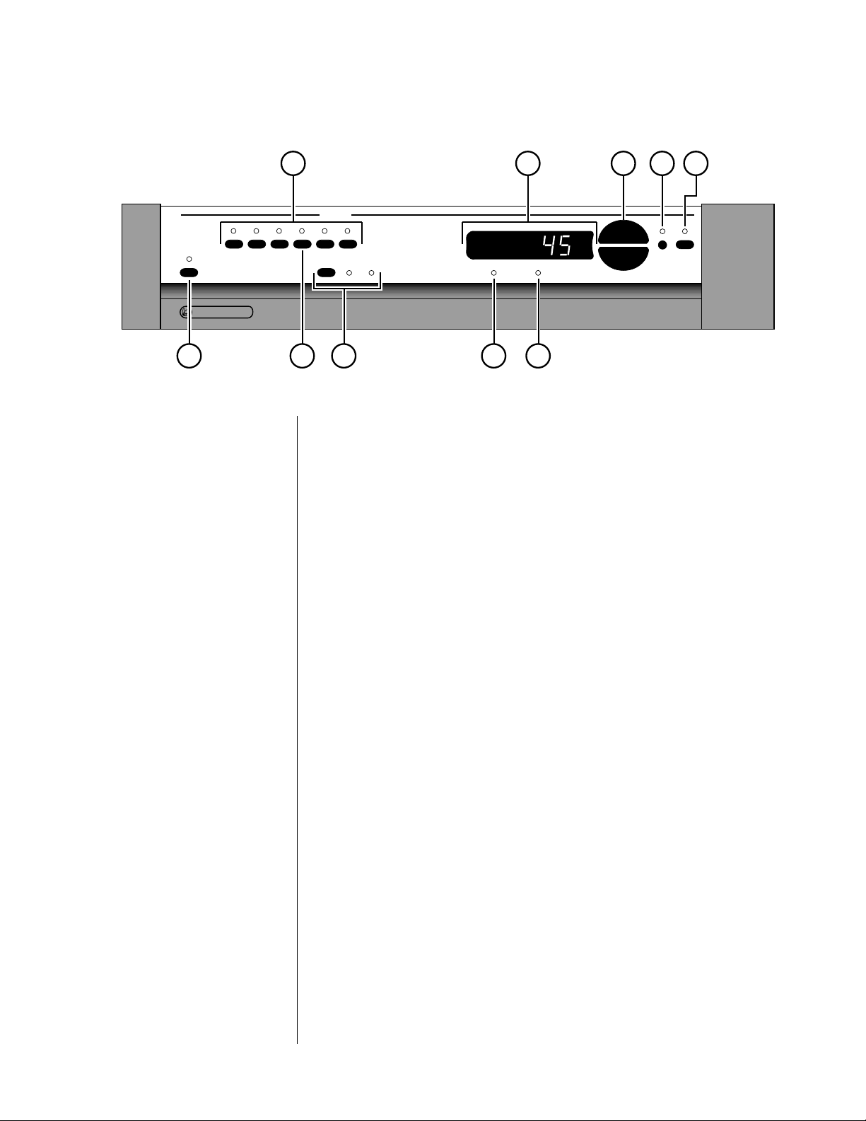
Front Panel
1 SOURCE SELECTION BUTTONS
These six buttons select audio signals from among the six audio inputs.
(Note that both cd1 and bal/aux are balanced inputs which use precision XLR connectors.) To use these selection buttons, choose the appropriate path (see path, below), and then make your selection.
2 MAIN DISPLAY
The main display provides information pertaining to the operation of the
PRE including relative volume levels, and is used in conjunction with the
buttons which surround it. At all volumes above a relatively quiet background level, and in all modes, the volume control enjoys a resolution of
0.5 dB. Thus a change of 10 decibels would be indicated by a change of
20 in the display.
The main display indicates the volume by default. In addition, it can also
display the balance. Right- and left-facing arrows are provided to indicate the direction of the balance offset, which is implemented in the
same 0.5 dB steps as the volume. Finally, the infrared receiver and transmitter for the remote control are positioned on the left side and center of
the main display, respectively.
3 VOLUME +/–
These up/down buttons are used to make adjustments on the PRE, apart
from source and path selection. While the volume +/– buttons normally
control the volume of the music system (main path), they can be used in
concert with other buttons to control several aspects of system performance (as indicated below).
9
Page 10

4 BAL (BALANCE)
Pressing this button followed by the volume +/– buttons will alter the
relative volume of the Left and Right speakers. The direction of the
balance shift is indicated by the green arrowhead indicators in the main
display, and the magnitude of the balance shift is shown in the main display. Both the volume +/– buttons and the main display will revert to
their normal operation (volume) after a few seconds.
5 MUTE
Pressing the
mute button will reduce the main output level of the pream-
plifier by a user-modifiable amount, ranging from 1 to 56 decibels (2 to
112 in the main display; the factory default is -20 decibels, which is -40
in the display). Pressing the mute button a second time without adjusting
the volume will return it to its previous setting. If you adjust the volume
with either the front panel buttons or the remote control while in the
mute mode, the preamplifier will adjust its volume from the muted vol-
ume and disengage the mute function. By so doing, the PRE avoids sud-
den, unexpected changes in volume. (See Using the PRE for information
on changing the factory default mute setting.)
6 MONO INDICATOR
This indicator LED will illuminate when the PRE is placed into mono
mode from its remote control. (Hint: set the balance by placing the PRE
into mono mode and then adjusting the balance to place the resultant
“center” image to be equidistant between your loudspeakers. This procedure will compensate for small differences in effective speaker sensitivity
and room placement inequalities, yielding the largest possible image
when you return to stereo operation by pressing the mono button on the
remote control again. There is no front panel button for the mono function.)
7 INVERTED POLARITY INDICATOR
This LED will illuminate to indicate that the polarity of the PRE has been
inverted. This inversion is accomplished by pressing the polarity button
on the remote control. Pressing the same button a second time restores
the normal, non-inverting operation of the PRE. There is no front panel
button for this operation, as the distinction is best heard from the listening position.
8 PATH SELECTOR
Pressing this button cycles among your various signal path options:
• main — this path determines which audio sources are sent to
the main outputs on the back of the PRE. Sources selected for
the main path are indicated in yellow on the front panel
LEDs.
• record — determines which audio sources are sent to the
PRE’s record output jacks. As a safety measure, the PRE will
prevent the selection of any recordable device as its own
source (to avoid feedback loops). If such a selection is attempted, the PRE will cause the appropriate LED to flash on
the front panel as a warning. The source selected for the
record path is indicated on the front panel in red LEDs.
10
Page 11

9 TAPE2/SSP INPUT
The tape2/ssp input of the PRE is special in that it may be used as either
a normal tape input such as you might find on other preamplifiers, or as
a dedicated surround sound processor loop. (See Using Surround Sound
Processors for more information.)
10 POWER & POWER LED
Assuming that the PRE’s power cord is connected to AC power, pressing
this latching power button connects the PRE to the AC mains and turns
on the unit. When power is restored after an interruption, the PRE will
be ready to operate (that is, it won’t be in standby mode), after a few
moments’ delay to allow its circuits to stabilize.
Front panel standby While most people will toggle the PRE between standby and
operate from the included remote control, if you need to do
so when the remote control is not nearby, you can press and
hold the
While the PRE is in standby, the LED above the power button is red.
When the PRE is ready to operate (that is, when it is not in standby
mode), this LED is amber. Naturally, when AC power is off, the LED is
off.
“path”
button for a few seconds.
11
Page 12
i n p u t s
tape2/
cd2 tuner tape1
LL
RR
PR O C E E D
ssp
R
p r e by MADRIGAL AUDIO LABORATORIES
RRLL
cd1 bal/aux
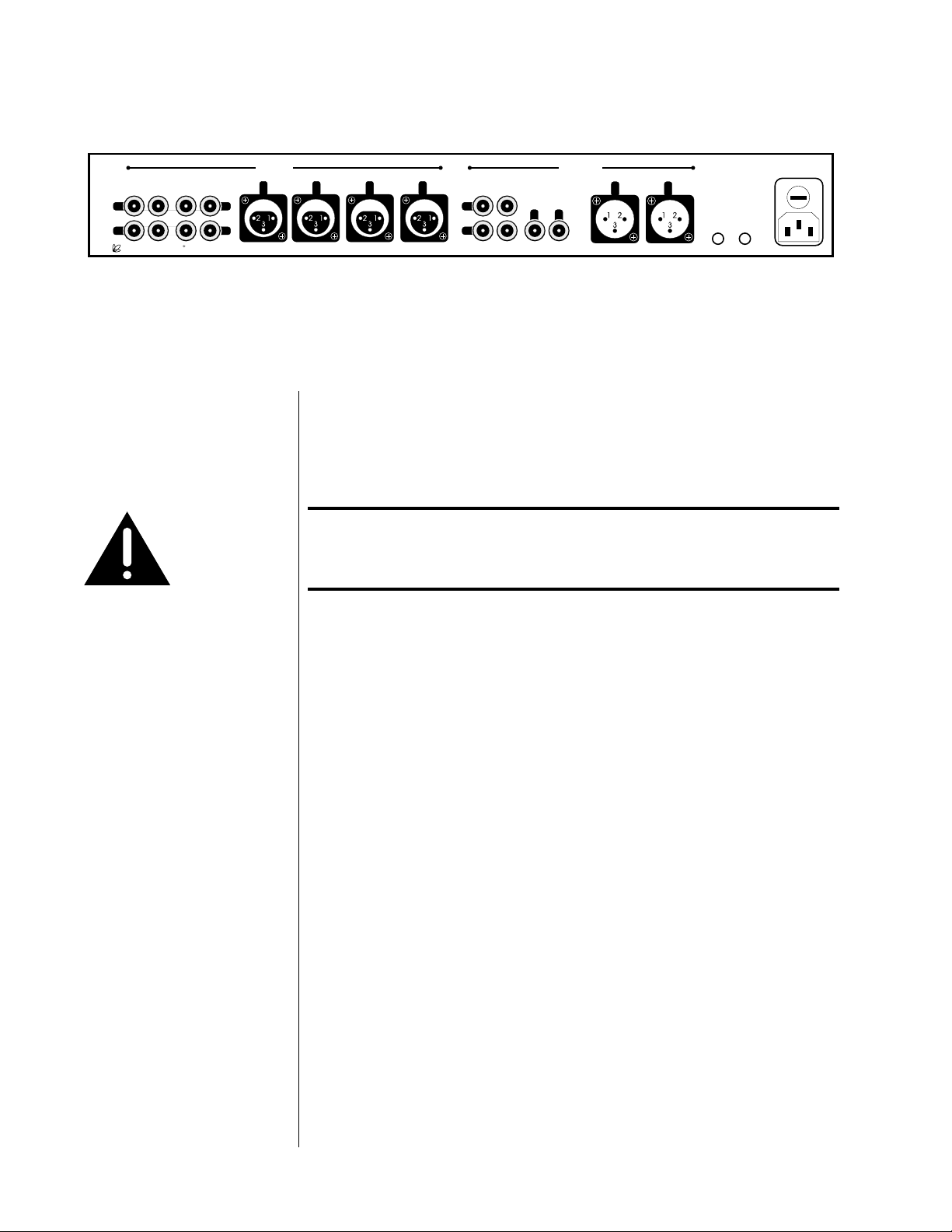
Rear Panel
Caution! Disconnect all associated equipment from the AC mains
~ ac mains
mains fuse:
.5A (250V) slo-blo 5x20mm
rec1 rec2/ssp
L
R
main out
R
o u t p u t s
L
main out
R
please see bottom panel for voltage and other information
L
remote
remote
IR
turn-on
BEFORE making any signal connections and applying power
to the PRE.
1 SINGLE-ENDED AUDIO INPUTS
Accepts right-channel and left-channel audio signals from source equipment with single-ended (RCA) outputs. Traditional single-ended audio
inputs are provided for a total of three components, designated: cd2,
tuner,
and tape1.
Connect the right-channel and left-channel single-ended outputs of your
various source components to the corresponding inputs on the PRE.
2 TAPE2/SSP INPUT
This single-ended audio input may be used either as a conventional input for a second tape deck or as a dedicated surround sound processor
loop. In the latter case, the front left and right outputs of your surround
sound processor would be routed to the tape2/ssp input and passed
through the PRE at unity gain (that is, with no change in volume), regardless of the volume control setting of the PRE.
The ssp function gives the outboard surround sound processor control
over the volume of all the loudspeakers (including those normally controlled by the PRE) when it needs that control. Returning the system to
two-channel stereo operation is then as simple as selecting a different
input. (See “Using Surround Sound Processors” for more information.)
12
Page 13
To choose between either the standard tape2 input function or the spe-
cial ssp input (which operates at unity gain), press and hold the
tape2/ssp button until its LED indicator changes color. Amber (matching
the other input LEDs) indicates normal tape2 functionality; green indicates the special ssp mode of operation. (Again, see “Using Surround
Sound Processors” for more information.)
3 BALANCED AUDIO INPUTS
Accepts right-channel and left-channel signals from source equipment
with balanced outputs. Provisions are made for two balanced signals via
high quality XLR connectors, designated
cd1 and bal/aux.
The pin assignments of these XLR-type female input connectors are:
Pin 1: Signal ground
21
3
Pin 2: Signal + (non-inverting)
Pin 3: Signal – (inverting)
Connector ground lug: chassis ground
These pin assignments are consistent with the standards recently adopted
by the Audio Engineering Society. Refer to the operating manuals of your
balanced-output line-level sources to verify that the pin assignments of
their output connectors correspond to the PRE. If not, wire the cables so
that the appropriate output pin connects to the equivalent input pin.
Connect the right-channel and left-channel balanced outputs of your
source components to the corresponding balanced inputs on the PRE.
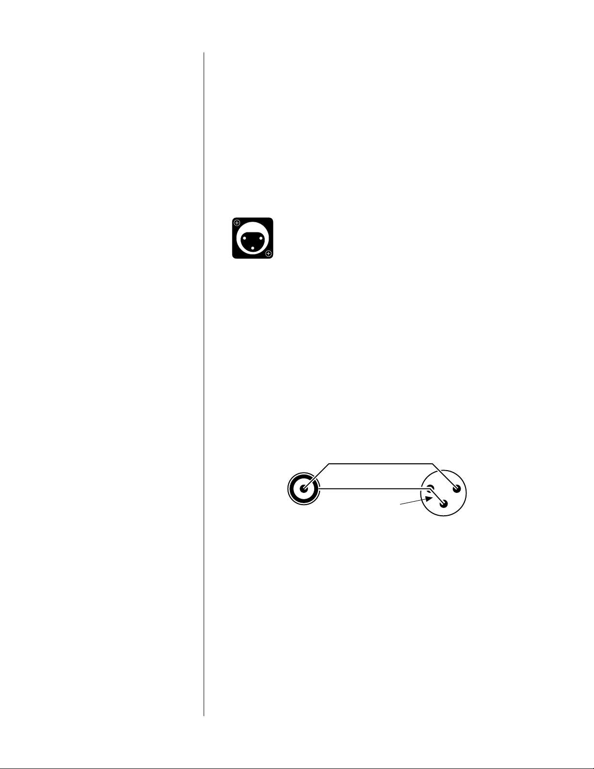
Note: If you do not have balanced sources and need more single-
ended inputs, it is possible to fabricate a cable to connect
line-level sources with single-ended output to these balanced
inputs:
1
2
22-gauge
3
buss wire
Male RCA
(connect to source)
Male XLR
(connect to PAV)
If you need them, your Proceed dealer can help you with these cables.
4 REC1 OUTPUT
These single-ended connections are used to provide a stereo signal to
the recording device which is connected to the tape1 input. Examples of
possible recording devices include a cassette deck, DAT, DCC, CD-R, or
Mini-Disc. Connect this output to the record input (sometimes also called
“line input” or simply “in”) of your recording device.
13
Page 14

The PRE incorporates a safety feature which prevents selecting the same
device as both the source to be recorded and the source to be monitored
at the same time. Were you to do so, a feedback loop would be created
which could be potentially damaging to your loudspeakers. If you attempt to select the same source for both recording and monitoring, the
second selection will be refused and the indicator light will blink several
times before reverting to the previously-selected input.
5 REC2/SSP OUTPUT
The
rec2/ssp output may be used in conjunction with a second record-
ing device or with a surround sound processor.
When used with a second recorder, connect this output to the record input (sometimes also called “line input” or simply “in”) of your recording
device. Under these circumstances, the rec2/ssp outputs will function
exactly as the rec1 outputs do. (See rec1 output, above.)
When used with a surround sound processor, connect this output to an
audio input on your processor. The source selected to be “recorded” on
the PRE will then be made available to your surround sound processor
for whatever hall effects or other signal processing you might desire.
Monitor the tape2/ssp input on the PRE to allow the front left and right
channels to be passed along to the appropriate power amplifiers and
speakers. (See “Using Surround Sound Processors” for more information.)
6 SINGLE-ENDED MAIN OUTPUTS
Single-ended (“unbalanced”) outputs are provided for compatibility with
a wide range of associated components, including power amplifiers and
electronic crossovers.
If you use the single-ended outputs, connect them to the corresponding
inputs of your power amplifier (or other device). Note that special features of the PRE enable it to be used optimally with a surround sound
processor as one of its inputs. We do not recommend having a surround
sound processor follow the PRE in the signal path. (For more information, see “Using Surround Sound Processors.”)
If you elect to use single-ended connection between your PRE and your
power amplifiers, connect the right-channel and left-channel singleended main out RCAs of the PRE to the appropriate balanced inputs of
the power amplifier.
7 BALANCED MAIN OUTPUTS
If your power amplifier is equipped with balanced (sometimes called
“differential”) inputs, it is best to use these balanced outputs on your
PRE. A balanced signal from preamplifier to power amplifier will offer
the highest possible performance with the best immunity from commonmode noise, such as radio frequency interference (RFI). The balanced
output signal is made available by way of precision male XLR connectors
(requiring female XLRs on the preamplifier end of the interconnecting
cable).
14
Page 15

The pin assignments of these XLR-type male outputs are:
Pin 1: Signal ground
12
3
Pin 2: Signal + (non-inverting)
Pin 3: Signal – (inverting)
Connector ground lug: chassis ground
Refer to your power amplifier’s operating manual to verify that the pin
assignments of its input connectors correspond to the PRE. If not, wire
the cable so that the appropriate output pin connects to the equivalent
input pin.
IR input tip polarity
Connect the right-channel and left-channel balanced
main outputs of the
PRE to the appropriate balanced inputs of the power amplifier.
8 REMOTE IR
A 1⁄8" “mini” jack in the lower right corner of the rear panel provides direct access to the infrared control circuitry of the PRE. This remote IR repeater input facilitates a wide range of installation options. If desired, the
PRE may be placed inside a cabinet or outside the normal line-of-sight in
the listening area, with the controlling IR signal being relayed to the PRE
by any of a number of commercially-available IR repeaters.
The incoming signal for the remote IR input should conform to widelyaccepted IR repeater standards: that is, the signal present should be between 3-12 volts DC at less than 100 mA current, with a positive tip polarity, as shown below:
+–
3-12 volts @ less
than 100 mA
Your Proceed dealer can help you take advantage of these design features to maximize your system’s versatility.
9 REMOTE TURN-ON
The PRE can control the status of certain compatible Madrigal power amplifiers, such as the Proceed AMP2. If this is desired, connect the remote
turn-on
output of the PRE to the remote turn-on input of those amplifiers
using a wire terminated with a 1⁄8" “mini” plug at both ends (available in
various lengths at electronics supply stores such as Radio Shack, or may
be custom made to length by your installing dealer). If more than one
Proceed amplifier is being used, simple “Y-adapters” may be used to
daisy-chain the turn-on signal for up to three AMPs turn-on inputs of
which are wired in parallel. The power amplifiers will then be turned on
when the PRE is on and placed in standby when the PRE is placed in
standby.
Note:the remote turn-on output provides a 300 msec long, 8 volt
positive pulse whenever the PRE turns on, and a 600 msec
long, 8 volt positive pulse whenever the PRE turns off. (This
information is sometimes needed in complex custom installations, and is provided for the designer/installer.)
15
Page 16

10 AC MAINS FUSE AND AC POWER RECEPTACLE
An ac mains fuse is provided which disconnects the PRE from the wall
outlet’s AC power under fault conditions. If this fuse should “blow” for
any reason, replace it only with the same value fuse (0.5A/250V slo-blo
5x20mm).
Caution! Replacing the ac mains fuse with a anything other than the
recommended value fuse will places the PRE at substantial
risk of damage!
Plug the supplied three-prong power cord into the ac power input re-
ceptacle provided before plugging the power cord into the wall. If a
longer AC power cord is required for your application, be sure to use a
three-conductor power cord which conforms to IEC standards.
Caution! The Proceed PRE has been safety-tested and is designed
for operation with a three-conductor power cord. Do not
defeat the “third pin” or earth ground of the AC power cord.
16
Page 17

Using the PRE
Listening & Recording The input buttons of the PRE are used to select both the source that will be
heard and the source that will be made available to any recording devices in
the system. The
When the main LED next to the path button is lit, any input selected will be
sent to the main outputs of the PRE, and (presumably) on to a power amplifier and loudspeaker. The selected input’s LED indicator will light and be amber in color.
When the record LED next to the path button is lit, any input selected will be
sent to the record outputs of the PRE for use by recording devices (or your
surround sound processor).
The main and record signal paths within the PRE are independent of each
other, allowing you to listen to one source while recording something else.
For example, you can easily make a copy of your favorite mix of music from
DAT to cassette for your car stereo, while listening to a CD of your choice.
If you have a three-head recorder (which allows you to monitor the recording
immediately after it is made) and would like to compare the source to the recording for quality control purposes, simply select the source to be recorded
(using the record path) and begin your recording. On your tape deck, be sure
to select “tape” on the “tape/source” switch. Then switch back to the main
path of the PRE and alternate between listening to the source and your tape
deck to make the comparison.
path button controls which of those selections is made.
Setting the Mute Level The factory default setting of the mute circuit is -20 dB (a change of 40 units
in the main display). It may be changed to suit your personal preference. To
change this setting:
1 PRESS AND HOLD THE MUTE BUTTON
Hold the mute button for approximately 5 seconds, until the main
display
the factory).
2 USE THE VOLUME +/– BUTTONS TO ADJUST THE MUTE SETTING
The volume +/– buttons will now adjust the size of the volume change
introduced by engaging the mute circuit to suit your personal preference.
If no change is made the PRE will “time out” after a few seconds of inactivity, returning to normal operation.
3 PRESS AND HOLD THE MUTE BUTTON TO CONFIRM YOUR CHANGE
Changes in the way the PRE normally operates require a conscious, deliberate act on your part. This is done to minimize the chance of having
your system changed accidently by someone who is simply exploring its
buttons. Thus (as outlined here), you must Hold a button, Change a setting, and then Hold the button a second time to confir m your change.
changes to show the current mute setting (-40 as delivered from
17
Page 18

Setting Input Offsets The PRE allows you to eliminate the sometimes significant differences in out-
put between your various source components by adjusting the input offset of
each input. Once adjusted, switching between sources will automatically introduce an change in volume within the PRE to “offset” the differences between
your components. This can avoid abrupt changes in level which might otherwise disrupt your listening sessions.
1 PRESS AND HOLD THE INPUT BUTTON YOU WISH TO ADJUST
Hold the
input button for approximately 5 seconds, until the indicator
LED above the selected input begins to blink. The main display will now
show the current input offset (initially 0 on all inputs).
2 USE THE VOLUME +/– BUTTONS TO ADJUST THE RELATIVE VOLUME
The volume +/– buttons will now adjust the relative change in volume
introduced when switching between different inputs. If no change is
made the PRE will “time out” after a few seconds of inactivity, returning
to normal operation.
3 PRESS AND HOLD THE INPUT BUTTON TO CONFIRM YOUR CHANGE
Changes in the way the PRE normally operates require a conscious, deliberate act on your part. This is done to minimize the chance of having
your system changed accidently by someone who is simply exploring its
buttons. Thus (as outlined here) you must Hold a button, Change a set-
ting, and then Hold the button a second time to confirm your change.
18
Page 19

Learning Remote Control
installing batteries in
the remote control
pre
audio
cd dvd aux
power
standby
input
record
mute
prev
rev fwd
stop
vcr1 vcr2 laserdisc polarity
123
tv/vcr1 cd1 cd2 mode
46
5
tape1 tape2 bal/aux status
78
tuner
menu
0
on
display input delay recall
screen
m1 m2
adjust channel
volume
play
volume
9
enter
m3
light
pause
mono
This remote control uses four AAA 1.5V batteries. Please be sure to match
the batteries with the (+) and (–) markings inside the battery compartment
during installation.
A: To Open and Close the Battery Compartment Cover
To open the battery cover, push the latch forward toward the top of the
remote control, and lift the latch up.
To close the battery cover, slide the battery cover straight back in (toward
the top of the remote) and push down until it “clicks” into place.
cblvcrtvsat
next
B: Low Battery Message
When the Liquid Crystal Display (LCD) flashes L_BAT, the batteries
should be replaced.
Note: Batteries should last about 6 months under normal conditions.
This remote control will retain its programmed memory for up to one
year after the batteries are removed and up to ten years after the batteries
go “dead”.
IMPORTANT NOTE:
subrearcenterbalancemaster
The PRE’s remote may be programmed to control up to eight devices, including the PRE. Before using the remote, it is important to remember to
m4
path
press the Device Control Selector button that corresponds to the unit you
wish to operate. Before using the remote with other products, follow the
instructions in Programming and Using the Remote Control.
It is also important to remember that many of the buttons on the remote
take on different functions, depending on the product selected using the
Device Control Selectors. Buttons not directly described on the following two pages do not function with the PRE, but are available for use
with other devices.
19
Page 20

1 LCD DISPLAY
This Liquid Crystal Display (LCD) shows messages as to which Device
Mode the remote is currently in, as well as various messages displayed
while programming your remote.
pre
audio
cd dvd aux
power
standby
input
mute
prev
rev fwd
record
adjust channel
volume
play
cblvcrtvsat
next
2 PROGRAMMING STATUS LED
This three-color (green/red/orange) LED indicates the remote’s status
when IR commands are being transferred from another compatible IR
remote. For more information on “teaching” the remote to learn IR
commands see Programming and Using the Remote Control.
3 DEVICE CONTROL SELECTORS
Press the
pre/audio button to use the remote control for operation of
the PRE Preamplifier. Note that the Programming Status LED will briefly
volume
stop
vcr1 vcr2 laserdisc polarity
123
tv/vcr1 cd1 cd2 mode
46
5
tape1 tape2 bal/aux status
78
on
display input delay recall
screen
9
tuner
entermenu
0
pause
mono
subrearcenterbalancemaster
blink red and the LCD Display will confirm your selection by switching
to AUDIO.
Press any of the other seven Device Control Selectors to use the remote
to control the functions of another audio/video device.
4TRANSPORT BUTTONS
This section of the PRE learning remote control groups the most-used
features of a source component together, be it a CD player, a VCR, or
m1 m2
m3
m4
path
light
a laserdisc player. This design allows you to put one or more of the
remote controls in your coffee-table collection away in a drawer, leaving
only the single PRE remote to provide all of the day-to-day commands
you require.
power
standby
volume
volume
5 NUMERIC KEYPAD
•
polarity
tape28display
cd1
bal/aux
mute
5
cd2
6
tape1
7
balance
9
path
tuner
0
mono
The numeric keypad of the PRE learning remote control can be
“taught” to emulate the numeric keypad you might have on the remote
controls of your cable decoder or television.
6 MEMORY BUTTONS
There are five memory buttons (m1~m4, power) that are designed to
store up to 15 commands in each button. Pressing any one of the memory
buttons will send out the series of commands that are stored in the button.
These buttons can be programmed to store Favorite Channels, Macro
Commands, or to “relocate” functions from one mode to another.
7 LIGHT BUTTON
All buttons and the LCD on the PRE remote are back-lit for seven
seconds when the light button is pressed. The backlight is extended
an additional seven seconds with any button press while the backlight
is on.
20
Page 21

power
standby
mute
8 PRE OPERATIONAL CONTROLS
This section of the learning remote contains the most often used controls
for the Proceed PRE.
volume
volume
polarity
cd1
5
cd2
6
tape1
7
tape2
8
bal/aux
9
tuner
0
mono
display
balance
path
• standby: pressing this button will place the PRE into standby
mode. As with all buttons on the learning remote, this button
can be “programmed over” if you wish. For example, you
may decide to leave the PRE “on” all the time and use the
standby button to turn another component on and off instead.
•
mute: pressing this button duplicates the function of the mute
button on the front panel, reducing the volume of the main
system by a user-selectable amount.
• volume +/–: these buttons normally adjust the overall system
volume, although they are also used in conjunction with other
buttons and/or menu items to vary most of the available system adjustments.
• polarity: inverts the polarity (sometimes inaccurately called
“absolute phase”) of the outputs of the PRE. A second press
of this button will restore the outputs to their original, noninverting polarity.
• cd1: selects the cd1 input (on either the main path or the
record path, depending which is selected).
• cd2: selects the cd2 input (on either the main path or the
record path, depending which is selected).
• tape1: selects the tape1 input (on either the main path or the
record path, depending which is selected).
• tape2: selects the tape2 input (on either the main path or the
record path, depending which is selected).
• bal/aux: selects the bal/aux input (on either the main path or
the record path, depending which is selected).
• tuner: selects the tuner input (on either the main path or the
record path, depending which is selected).
• mono: sums the left and right channels of the PRE to a monophonic signal, which is then routed to both left and right outputs.
• display: pressing this button will turn off the front panel display of the PRE to facilitate listening to music (or watching
movies) in a darkened room without visual distractions. The
PRE’s display will turn back on momentarily when adjusting
the unit’s operation in order to acknowledge the changes.
The display may be returned to its normal, always-on mode
by pressing the display button again.
• path: pressing this button toggles the PRE between the main
and record signal paths. Having selected a path, subsequent
source selections affect only that path.
• balance: pressing this button temporarily allows the volume +/
–
keys to affect the balance of the left and right speakers rather
than the overall volume.
For more information on the teaching your remote new functions, see
Programming and Using the Remote Control.
21
Page 22

Programming and Using the
Remote Control
The PRE is equipped with a powerful backlit remote control that will control
up to seven additional devices, in addition to all the features of the PRE. It
may also be programmed to “learn” the functions from most current infrared
remote controls. This means that once programmed, the PRE remote will not
only operate your PRE, but most TV sets, VCRs, DVD and LD players, satellite
systems, set-top converters and other IR controlled home theater or home
automation equipment.
pre-programmed functions To operate the PRE, be certain that you have pressed the pre/audio Device
Control Selector. Note that the Programming Status LED will briefly blink red
and the LCD Display will confirm your selection by switching to AUDIO. In this
pre-programmed mode, the remote control takes on the functions of the PRE.
learning set-up In addition to it’s preprogrammed functions, the PRE remote may be taught to
learn the commands from almost any infrared remote that is used to operate
audio, video, home theater or home automation equipment. This enables the
PRE remote, once programmed, to replace a collection of remotes, and operate
your entire entertainment system from one, powerful command center.
The PRE remote has the ability to learn new functions from your original remote
controls:
• There are 8 “pages” of learning with each page corresponding to the 8 Device modes on the Remote control: pre/audio,
cd, dvd, aux, sat, tv, vcr and cbl.
• All buttons in all Device modes can learn, except the light button.
• The 8 Device buttons at the top of the remote control labeled
(pre/audio, cd, dvd, sat, tv, vcr and cbl) learn only in the Audio
mode.
• Learned functions override any existing preprogrammed functions
on the remote control.
• Learned functions are automatically erased when a new function is
learned on the same button.
• To erase a learned function and return to an original
preprogrammed function, please refer to the section Erasing
Learned Functions.
NOTE: If you inadvertently overwrite one or more pre-programmed PRE com-
mands in your PRE remote control, the PRE itself can send all of the necessary IR
commands from its main display window, enabling you to teach the PRE remote
both its pre-programmed commands and a few other, optional commands which
you might find useful. (Please refer to the section “Teaching PRE Functions to its
Remote Control”.)
22
Page 23

learning new functions on the
main keypad
1 Select the mode in which you wish to learn the new function
by pressing the corresponding Device button.
2 Place the PRE remote and the original remote control to be
learned from, on a flat surface. Line up the remote controls
head-to-head, about two to three inches apart.
rev fwd
mute
input
stop
volume
pause
prev
volume
play
next
audio
standby
pre
power
record
cd dvd aux
adjust channel
cblvcrtvsat
2" to 3"
Device Buttons
pre
audio
power
standby
input
mute
prev
rev fwd
stop
Play Button
cd dvd aux
adjust channel
record
volume
play
volume
pause
3 Press and hold both the Device button selected in Step 1
and the play button for about three seconds, until the LCD on
cblvcrtvsat
NOTE: Each of the following steps must be completed within 20 seconds. If
the PRE remote shows LEARN. the PRE remote is now in the
learning mode.
the remote does not receive any new commands within the allotted time, it
next
will return to its normal operating mode.
4 Press and release a button on the PRE remote you have
selected to learn the new function. The LCD will show
READY.
5 Press and hold the button on the original remote control for
about 3 seconds from which you are learning the new function.
The LCD on the PRE remote will show – – – – indicating that it
is receiving the information from the original remote control.
6 Release the button on the original remote control. The LCD
on the PRE remote will show RETRY.
7 Press and hold the same button on the original remote once
again, for about three seconds. The LCD on the PRE remote
will flash GOOD, the Device Mode and then return to LEARN,
verifying that the new function has been learned.
Repeat Steps 4 through 7 for any other buttons you wish to learn new
functions.
8 Once you have completed the learning for all the desired but-
tons in a Device mode, store the learned functions by pressing the device and play buttons simultaneously, once again.
The LCD in the PRE remote will show SAVED and then return
to
the Device Mode. The remote has now returned to the original operating mode.
Once you have stored the learned functions, test the buttons that have been
taught. If any of the buttons do not operate as they should, please repeat from
Step 1 for those buttons.
NOTE: If the LCD shows FAI L at any time during the learning process, the PRE
remote was unable to learn the new functions. Please repeat from Step 4. If
the remote continues to show FAI L during the learning process, please try the
following suggestions:
23
Page 24

• Increase or decrease the head-to-head distance between the
two remote controls, within a 1 to 5 inch range.
• Increase or decrease the time you press-and-hold the button on
the original remote control in step 5, for 1 to 2 seconds.
• Avoid fluorescent lights or strong sunlight during the set-up.
These lighting conditions can cause interference with the
learning process.
• Verify that the original remote control contains fresh batteries.
Some remote controls operate at non-standard IR, UHF or ultrasonic frequencies,
and are unable to be learned. If you continue to experience difficulty during
set-up, please contact authorized dealer for assistance.
learning new functions
on device buttons
The eight Device buttons at the top of the remote control can also learn new
functions. These buttons can only be set up in the Audio mode. If a new function is learned on a Device button, the new function will override any existing
preprogrammed information on the Device button.
1 Place the PRE remote and the original remote control to be
learned from, on a flat surface. Line up the remote controls
head-to-head, about two to three inches apart.
2 Press-and-hold both the audio and play buttons simultaneously,
for about three seconds, until the LCD on the PRE remote
shows LEARN. The PRE remote is now in the learning mode.
NOTE: Each of the following steps must be completed within 20 seconds. If the
remote does not receive any commands within the allotted time, it will return
to its normal operating mode.
3 Press-and-release one of the eight Device buttons on the PRE
remote. The LCD will show READY.
4 Press-and-hold the button on the original remote control you
wish to teach into the PRE remote, for about three seconds.
The LCD on the PRE remote will show – – – – indicating that it
is receiving the information from the original remote control.
5 Release the button on the original remote control. The LCD
on the PRE remote will show RETRY.
24
6 Press-and-hold the same button on the original remote again,
for about three seconds. The LCD on the PRE remote will
flash GOOD, the Device Mode and then return to LEARN,
verifying that the new function has been learned.
Repeat Steps 3 through 6 for any other buttons you wish to learn new
functions.
7 Once you have completed the learning for all the desired
Device buttons, store the learned functions by pressing the
audio and play buttons simultaneously, once again. The LCD
in the PRE remote will show SAVED and then return to the
AUDIO mode. The remote has now returned to the original
operating mode.
Page 25

erasing learned functions
To erase learned functions, please refer to the following procedures:
Erasing Individual Buttons:
1 Press the Device button for the mode where the learned func-
tion has been stored.
2 Press-and-hold the Device and the play buttons simultaneously,
for about three seconds, until the LCD shows LEARN.
3 Press-and-release the button to be erased. The LCD will show
READY.
4 Press the light button. The LCD will flash ERASE, CLEAR, the
Device Mode and then return to LEARN.
Repeat steps 3 and 4 for any other buttons to be erased.
5 To return to the normal operating mode, press the Device
and play buttons simultaneously.
The learned functions on the selected buttons have now been erased.
The pre-programmed functions for these buttons will now operate on the
remote control.
Erasing All Buttons in One Device Mode:
1 Press the Device button for the mode to be erased.
2 Press-and hold the Device and play buttons simultaneously,
for about three seconds, until the LCD shows LEARN.
3 Press-and-hold the Device and light buttons simultaneously
for approximately five seconds and then release the buttons.
The LCD will flash ERASE and then alternately CLEAR and the
Device Mode.
NOTE: When the LCD on the remote returns to the
Device Mode
, all the learned
functions in the selected Device mode have been erased. All the buttons in that
Device mode will now operate with the preprogrammed functions in that mode.
Erasing All Buttons in All Device Modes:
1 Press-and-hold the tv Device Button and the light button si-
multaneously, for approximately ten seconds. The LCD will
flash ERASE ten times, flash CLEAR and then return to the TV
mode.
When the LCD on the remote returns to tv, all the learned functions in all
eight Device modes have been erased. All the buttons in all Device modes
will now operate with the preprogrammed functions in their respective modes.
operation After you have programmed the remote control for your equipment, use the
following procedures to operate your home entertainment system:
1 Press the Device button that you wish to operate: e.g., to oper-
ate a TV press the tv Device button; to operate a VCR, press the
vcr Device button, etc.
2 Aim the remote control at the device and press the power/
standby
3 Press the buttons that send out the commands you desire.
button to turn on the device.
25
Page 26

NOTE: Some audio/video devices have separate buttons for Power On and
Power Off. To operate these devices on the remote, press the corresponding
Device Button to turn the equipment ON and press the power/standby button
to turn the equipment OFF or place the equipment in the Standby mode.
Please try all the functions of this remote control with your equipment. The
most common functions are labeled on the remote. However, some of the
secondary functions might be stored under a button that has a different name
from the one on your original remote control.
device buttons
main device mode
automatic audio mode
Pressing a Device button at the top of the remote performs the following
functions:
1 Changes the Device mode on the PRE remote control.
2 Sends out a Power ON command for the Device, if applicable.
3 Sends out a preprogrammed or learned Audio receiver/
preamplifier INPUT SELECTION, on second press of the buttons
in A–XXX mode, if applicable.
4 Toggles between the Main Device mode and the Automatic Audio
Mode. (See “Automatic Audio Mode” below.)
NOTE: Device buttons can learn new information only in the Audio mode.
When the main Device mode is displayed in the LCD, the PRE remote will
operate in a standard operating mode and all the buttons will operate in the
preprogrammed, learned and punch-through features for that Device mode.
The PRE remote is designed to provide convenient and continuous operation of
your home theater system’s devices. You can have full and immediate access to
the PRE’s volume and surround controls while maintaining control of any of the
other seven different device modes of the remote control by pressing the same
Device button a second time.
26
The Automatic Audio Mode enables you to watch a video program or listen to
a CD and also adjust audio volume and surround levels in the same Device
mode. The LCD will show a A–XXX indicating that the remote control is in the
Automatic Audio mode.
Example: Pressing the sat Device button a second time will change the LCD
from SAT to A_SAT.
In the Automatic Audio Mode, you gain control of the PRE volume and surround
levels while also maintaining full control of the Channel, Transport cursor and
Numeric Keypad of the device.
Page 27

remote control
function worksheet
Planning Your Remote Control
For your convenience, we have included the worksheets on the following two
pages on which you may plan which additional functions you will assign to
which buttons on the PRE remote control. We suggest photocopying this page
and then planning your programming before getting into it too heavily. Refer to
the drawing below which shows the PRE remote at the left and the PRE remote
at the right with numbers on each button which correspond to the numbers on
the worksheets that follow. Refer to this drawing when learning/programming
additional remotes into the PRE remote control. A little time spent planning can
make the teaching process go much more smoothly, and it provides you with a
ready reminder of which commands you placed where during the first day or
two of use. After that, you will probably find everything to be second nature,
and you may wonder how you ever got along without this “all-in-one” remote
control. An asterisk (*) indicates buttons normally used by the PRE.
pre
audio
power
standby
input
mute
prev
cd dvd aux
adjust channel
record
volume
cblvcrtvsat
next
1234
5678
9
10 11
20
15121613 14
17
rev fwd
stop
vcr1 vcr2 laserdisc polarity
123
tv/vcr1 cd1 cd2 mode
46
tape1 tape2 bal/aux status
78
on
screen
m1 m2
play
volume
5
tuner
0
display input delay recall
light
pause
9
mono
entermenu
m3
subrearcenterbalancemaster
m4
path
222423
18 19
25
29 30 31 32
37
41 42 43 44 45
51 52 53 54
21
26 27 28
38 39 40
49484746
55
36353433
50
56
27
Page 28

remote control
function reference
no. button name device device device device
1-8 * device name _________ _________ _________ _________
9 * power/standby _________ _________ _________ _________
10 adjust + _________ _________ _________ _________
11 channel + _________ _________ _________ _________
12 *input/mute _________ _________ _________ _________
13 record/ _________ _________ _________ _________
14 adjust – _________ _________ _________ _________
15 channel – _________ _________ _________ _________
16 prev/ _________ _________ _________ _________
17 next/ _________ _________ _________ _________
18 stop/ _________ _________ _________ _________
19 pause/ _________ _________ _________ _________
20 *volume/ _________ _________ _________ _________
21 *volume/ _________ _________ _________ _________
22 fwd/ _________ _________ _________ _________
23 rev/ _________ _________ _________ _________
24 play/ _________ _________ _________ _________
25 vcr1/1 _________ _________ _________ _________
26 vcr2/2 _________ _________ _________ _________
27 laserdisc _________ _________ _________ _________
28 *polarity _________ _________ _________ _________
29 tv/vcr1/4 _________ _________ _________ _________
30 *cd1/5 _________ _________ _________ _________
31 *cd2/6 _________ _________ _________ _________
32 *mode _________ _________ _________ _________
* An asterisk indicates buttons normally used by the PRE.
28
Page 29

no. button name device device device device
33 * tape1/7 _________ _________ _________ _________
34 * tape2/8 _________ _________ _________ _________
35 * bal/aux/9 _________ _________ _________ _________
36 status _________ _________ _________ _________
37 menu _________ _________ _________ _________
38 * tuner/0 _________ _________ _________ _________
39 enter _________ _________ _________ _________
40 * mono _________ _________ _________ _________
41 on screen _________ _________ _________ _________
42 * display _________ _________ _________ _________
43 input _________ _________ _________ _________
44 delay _________ _________ _________ _________
45 recall _________ _________ _________ _________
46 master _________ _________ _________ _________
47 * balance _________ _________ _________ _________
48 center _________ _________ _________ _________
49 rear _________ _________ _________ _________
50 sub _________ _________ _________ _________
51 m1 _________ _________ _________ _________
52 m2 _________ _________ _________ _________
53 m3 _________ _________ _________ _________
54 m4 _________ _________ _________ _________
55 light _________ _________ _________ _________
56 * path _________ _________ _________ _________
* An asterisk indicates buttons normally used by the PRE.
29
Page 30

punch-throughs
Remote Control
Advanced Features
After you set up the remote control to operate your equipment, you can also
program advanced features on the remote control. The advanced features are
designed to enhance the use of the remote control with your home entertainment system.
volume control
“punch-through”
The PRE’s remote may be programmed to operate the volume + – controls
and mute button from either the TV or PRE to operate in conjunction with
any of the eight devices controlled by the remote. For example, since the PRE
will likely be used as the sound system for TV viewing, you may wish to
have the PRE’s volume activated when the remote is set to run the TV. Either
the AUDIO or TV volume control may be associated with any of the remote’s
devices.
NOTE: When this feature is active, the AUDIO or TV volume and mute will
override any existing volume controls in that mode.
To program the remote for Volume Punch-Through, follow these steps:
1 Select the mode that you wish to program for Vol ume Con-
trol “Punch-Through.”
2 Press the corresponding Device button (e.g., tv, sat, etc.) and
the mute button simultaneously. SET will appear in the LCD.
3 Press the adjust + button. PUNCH will appear in the LCD.
4 Press either the pre/audio or tv Device selector, depending
on which system’s volume control you wish to have attached
for the punch-through mode. AUDIO or TV will flash in the
LCD.
Example: To have the PRE’s volume control be activated even though the
remote is set to control TV, first press the tv Device control selector, and the
mute button at the same time. Next press the adjust + button, followed by the
pre/audio Device control selector.
30
To return to the original setting, follow these steps:
1 Select the mode that you want to turn off the Volume Control
“Punch-Through” and press the corresponding Device button
(e.g., tv, sat, etc.) and the mute button simultaneously. SET
will appear in the LCD.
2 Press the adjust + button. PUNCH will appear in the LCD.
3 Press the same Device button again. The Device mode will
flash in the LCD.
The AUDIO or TV Volume Control “Punch-Through” is now turned off. The
VOLUME and MUTE of the original device will operate on the remote control.
Page 31

channel control
“punch-through”
You can program the remote so that either the Sat or Cable Channel Controls
(channel + or channel –) will also operate in other modes on the remote control.
NOTE: When this feature is active, the SAT or Cable channel + or channel – will
override any existing channel controls in that mode.
To program the remote for Channel Control Punch-Through, follow these steps:
1 Press the Device button for the device you wish to have asso-
ciated with the volume control (e.g., sat or cbl.) and the mute
button simultaneously. SET will appear in the LCD.
2 Press the adjust – button. PUNCH will appear in the LCD.
3 Press either the sat Device button to set-up for the SAT Chan-
nel Control or the cbl Device button to set-up for the Cable
Channel Control. Either SAT or CBL will flash in the LCD,
depending on the Device button selected.
SAT or Cable Channel Controls will now override the original channel + and
channel – in this mode.
To return to the original setting, follow these steps:
1 Select the mode that you want to turn off the Channel Control
“Punch-Through” and press the corresponding Device button
and the mute button simultaneously. SET will appear in the
LCD.
transport control
“punch-through”
2 Press the adjust – button. PUNCH will appear in the LCD.
3 Press the same Device button again. The Device mode will
flash in the LCD.
The SAT or Cable Channel Control “Punch-Through” is now turned off. The
CHANNEL UP and DOWN of the original device will operate on the remote
control.
You can set up your remote control so that VCR or CD Transport Controls (Play,
Stop, Fast Forward, Rewind, Pause and Record) will also operate in other modes
on the remote control. An example would be to control your VCR functions
while operating the remote control in the tv mode.
NOTE: When this feature is active, the VCR or CD functions (Play, Stop, Fast
Forward, Rewind, Pause and Record) will override any existing functions
preassigned to these buttons in than mode.
To program the remote for Transport Control Punch-Through, follow these steps:
1 Press the Device button for the device you wish to have asso-
ciated with the volume control (e.g., tv or sat.) and the mute
button simultaneously. SET will appear in the LCD.
2 Press the play button. PUNCH will appear in the LCD.
31
Page 32

memory buttons There are five memory buttons (m1~m4, power/standby) that are designed to
power
standby
input record
mute
Memory Buttons
adjust channel
3 Press either the vcr Device button to set-up for VCR Transport
Control or the cd Device button to set-up for CD Transport
Control. VCR or CD will flash in the LCD, depending on the
Device button selected.
The VCR or CD Transport Controls (Play, Stop, Fast Forward, Rewind, Pause
and Record) will now override the original functions of the buttons in this
mode.
To return to the original setting, follow these steps:
1 Select the mode that you want to turn off the Transport Con-
trol “Punch-Through” and press the corresponding Device
button and the mute button simultaneously. SET will appear in
the LCD.
2 Press the play button. PUNCH will appear in the LCD.
3 Press the same Device button again. The Device mode will
flash in the LCD.
The VCR or CD Transport Control “Punch-Through” is now turned off. The
original functions assigned to these buttons are restored.
store up to 15 commands in each button. Pressing any one of the memory
buttons will send out the series of commands that are stored in that button.
You can either turn on or off up to eight devices by storing Power on/off
commands or use it to select the favorite channels by storing channel numbers
into the button. You can also combine Power on/off, select favorite channel
and any of the features in the remote control to these buttons.
m1 m2
m3
m4
light
path
You can program any of the memory buttons (m1~m4, power/standby) in
AUD mode and it will send out the stored commands in Audio, CD, DVD and
AUX modes. You can also program the memory buttons in SAT mode, and it
will send out the stored commands in Satellite, TV, VCR and CBL modes.
• MACRO COMMANDS:
Memory Buttons can store and emit up to 15 commands including multiple
Power On/Off sequences. As an example, in the Audio mode, the power/
standby
Memory Button can be programmed to turn on the TV, turn on the
PRE, turn on the VCR and turn on the Satellite receiver with one button push.
• FAVORITE CHANNELS:
Memor y Buttons can provide direct access to your channel with a one-button
push. As and example, in the SAT device mode each of the Memory Buttons m1,
m2, m3 and m4 can provide direct access to a different satellite channel by send-
ing out the three-digit channel number for that channel to your satellite receiver
with a one-button push.
32
Page 33

programming
memory buttons
To program the Memory Buttons, follow these steps:
1 Select the section that you wish to program the Memory But-
ton in by pressing the corresponding Device button (audio or
sat) and mute button, simultaneously. SET will appear in the
LCD.
2 Press one of the Memory Buttons (m1, m2, m3, m4 or power/
standby
5)_##
NOTE: The mute button is used to designate POWER/STANDBY commands
) into which you wish to store the functions. M(1-
will appear in the LCD.
during Memory button programming.
3 Press in up to fifteen commands that you want stored in that
Memory button. Each successive button selection will appear
as M(1-5)_(01-15) in the LCD.
You can select functions from another mode by first pressing
the corresponding Device button and then the buttons where
those functions are located in that mode. The pressing of a
Device button also counts as one command.
NOTE: Each insertion of a Device Button adds a 1/2-second delay to the
command sequence.
4 Press the channel + button to store your selections. SAVE will
flash three times in the LCD to confirm the programming.
IMPORTANT NOTE: If you attempt to store more than 15 commands, the entire
sequence of macros entered will clear and you will need to start over.
NOTE: It can take up to 15 seconds to send out 15 commands from a memory
button. Please continue to point the remote control at the device(s) until all the
commands on the Memory Button have been sent out. This will ensure that all
the commands are received by the device(s).
Example: To program your TV, Cable Box and the PRE to turn on when the
power button is pressed, first press-and-hold the sat and mute buttons until SET
appears in the LCD. Next, press the mute button to enter the Power commands
for the PRE. Press tv to select the TV mode, and then press the mute button
again, to select T V Power. Finally, press cbl followed by the mute button to
select Cable power. Press the channel + button to enter the commands.
After following these steps, each time you press the power/standby button,
after either the sat, tv, vcr or cbl Device control selector has been pressed, the
remote will send the “Power On/Off” command.
33
Page 34

erasing memory buttons
To erase the Memory Buttons, follow these steps:
1 Select the mode (AUD or SAT) in which you want to erase the
Memory button.
2 Press the corresponding Device button (audio or sat) and
mute button simultaneously. SET will appear in the LCD. Press
the Memory button to be erased.
M(1-5)_## will appear in the
LCD.
3 Press the channel + button. SAVE will flash in the LCD. The
Memory button is now erased.
NOTE: Any previously stored commands on a Memory button will be erased
when new commands are stored on the same Memory button.
changing the lcd display Twenty-four different LCD displays can be selected for each Device mode of
the remote control. To select an alternate LCD display, please use the following
procedure:
1 Press-and-hold the Device button for which you would like to
change the LCD setting.
2 While pressing the Device button, press-and-release the
pause button. Each time the pause button is pressed, the
LCD will show one of twenty-four displays.
3 Release the Device button when you find the new LCD dis-
play you wish to assign to the Device mode.
• CHOICE OF LCD DISPLAYS
TV VCR CABLE SAT AUDIO CD
DVD AUX TV2 VCR2 TUNER AMP
TAPE1 TAPE2 WEBTV SURR DAT PROJE
AUX2 LD AUD2 LIGHT DSS AV
• LCD DISPLAYS IN THE AUTOMATIC AUDIO MODE
A-TV A-VCR A-CAB A-SAT AUDIO A-CD
A-DVD A-AUX A-TV2 S-VC2 A-TUN A-AMP
A-TA1 A-TA2 A-WEB A-SUR A-DAT A-PRJ
A-AX2 A-LD A-A2 A-LIT A-DSS A-AV
34
Page 35

Teaching PRE Functions
to its Remote Control
If you inadvertently overwrite one or more PRE commands in your PRE remote
control, never fear—you don’t have to obtain another PRE remote in order to
re-teach your own its PRE-specific commands. The PRE itself can send all of the
necessary IR commands from its main display window, enabling you to re-teach
the PRE remote any or all of its pre-programmed commands, as well as some
optional special commands which are available to solve specific installationrelated difficulties.
The PRE has two special modes of operation into which is may be placed in
order to facilitate the “teaching” of remote control commands to its own (or
any other) learning remote control. The first allows you to easily teach the
commands for which there are corresponding front panel buttons. The second
allows you to teach “special” commands to the remote control for which there
are no corresponding front panel buttons.
Device Buttons
pre
audio
power
standby
input
mute
prev
rev fwd
Teaching PRE Front
Panel Commands
cd dvd aux
cblvcrtvsat
adjust channel
record
volume
play
next
1 Press and hold the balance (BAL) button on the front panel un-
til “0L” appears in the display. A momentary press of the bal-
ance
button will, of course, simply place the PRE in balance
mode
. When you press and hold the balance button instead,
the PRE will wait for a few seconds to make sure that your
press-and-hold action is quite deliberate, and then enter a teaching mode which allows you to program a learning remote control with infrared (IR) commands. The PRE’s main display will
show a number and the letter “L” (for “Learn”) when in this
mode.
The PRE will display a “0L” code when it has entered its teaching mode and is ready to help the remote control learn the
commands that correspond to the PRE’s front panel buttons. If
no further buttons are pressed within approximately ten seconds, the PRE will “time out” and return to normal
operation.
2 Line up the IR window of the PRE remote control with
the center of the main display of the PRE, at a distance of
approximately 2"-3".
3 Press and hold both the pre/audio Device and the play but-
ton for about three seconds, until the LCD on the PRE remote
shows LEARN. The PRE remote is now in the learning mode.
NOTE: Each of the following steps must be completed within 10 seconds. If
the remote does not receive any new commands within the allotted time, it
will return to its normal operating mode.
4 Press and release the corresponding button on the PRE remote
you have selected to re-learn the function. The LCD will show
READY.
stop
Play Button
volume
pause
Notice that a yellow LED in the main display lights up briefly
after you press a button. This LED indicates that the PRE is
transmitting the command which corresponds to the button you
just pushed. You may repeat this process until all commands
have been learned by your remote control.
35
Page 36

5 Press and hold the corresponding button on the PRE for about
3 seconds. The LCD on the PRE remote will show – – – –
indicating that it is receiving the information from the original
remote control.
6 Release the button on the PRE. The LCD on the PRE remote
will show RETRY.
7 Press and hold the same button on the PRE once again, for
about three seconds. The LCD on the PRE remote will flash
GOOD, the Device Mode and then return to LEARN, verifying
that the new function has been learned.
Repeat Steps 4 through 7 for any other buttons you wish to re-learn from the
front panel of the PRE.
8 Once you have completed the learning for all the desired but-
tons, store the learned functions by pressing the device and
play buttons simultaneously, once again. The LCD in the PRE
remote will show SAVED and then return to the Device Mode.
The remote has now returned to the original operating mode.
Once you have stored the learned functions, test the buttons that have been
taught. If any of the buttons do not operate as they should, please repeat from
Step 1 for those buttons.
NOTE: If the LCD shows FAI L at any time during the learning process, the PRE
remote was unable to learn the new functions. Please repeat from Step 4.
Teaching Other
PRE Commands
9 When finished, exit the programming mode of the PRE by press-
ing and holding the balance button again. You could, of course,
also wait for the PRE to “time out” and return to normal operation.
Alternatively, you may wish to continue on to the next section to
teach your remote control the PRE’s special commands, in which
case you should go directly to step #2.
As mentioned above, the PRE has the capability to teach its own (or other)
learning remote controls special commands for which there are no frontpanel counterparts. These include the commands that toggles the PRE
between stereo/mono, normal/inverted polarity, and display on/off modes.
In addition, there are several “hard assignment” commands available in the PRE
which will place it into a certain mode of operation regardless of its current state.
For example, a hard assignment command to enter standby will leave the PRE in
standby if already there, or switch it to standby if it is currently operating. This
type of hard assignment command is especially helpful when you do not necessarily know the current status of the PRE, as might be the case in a multi-room
home entertainment system (for example).
36
Page 37

1 Press and hold the balance (BAL) button until “0L” appears in
the display. A momentary press of the balance button will, of
course, simply place the PRE in balance mode. When you press
and hold the balance button instead, the PRE will wait for a
few seconds to make sure that your press-and-hold action is
quite deliberate, and then enter a teaching mode which allows
you to program a learning remote control with infrared (IR)
commands. The PRE’s
main display will show a number and
the letter “L” (for “Learn”) when in this mode.
The PRE will display a “0L” code when it has entered its
teaching mode and is ready to help the remote control learn
the commands that correspond to the PRE’s front panel buttons. If no further buttons are pressed within approximately
ten seconds, the PRE will “time out” and return to normal
operation.
2 Press and hold the mute button until “1L” appears in the dis-
play. You will see the usual small yellow LED light up when
you first press the mute button, indicating that the PRE is
sending the IR code for the mute function. By continuing to
hold this button, however, you are instructing the PRE to give
you access to programming options beyond those represented
by the front panel buttons.
special commands table
The table below lists the special commands which are available
for the PRE. In the second column are the programming “codes”
used in the main display to represent those special commands.
stereo/mono toggle 1L
polarity normal/inverted toggle 2L
display on/off toggle 3L
direct access to main path 4L
direct access to record path 5L
direct access to operate 6L
direct access to standby 7L
direct access to mute on (e.g., volume reduced)8L
direct access to mute off (e.g., volume normal)9L
3 Use the volume +/– buttons to select the code that corresponds
to the special function you would like to teach your remote
control. Pressing the volume + button will increase the program
code number by one; volume – will decrease the program code
number by one. Select the desired code number from the list
above.
4 Momentarily press the mute button to transmit that code. Line
up the IR window of the PRE remote control with the center
of the main display of the PRE, at a distance of approximately
6"-12". Select the to-be-learned button on the remote, then
fire the selected code from the PRE.
37
Page 38

Notice that a yellow LED in the main display lights up briefly
after you press mute. This LED indicates that the PRE is transmitting the command which corresponds to the code you
have selected. You may repeat the process of selecting special
commands (using volume +/–) and then transmitting them
(pressing mute) until all desired commands have been
learned by your remote control.
5 Repeat the process of “teaching” new commands to the various
buttons on the PRE remote control until all desired commands
have been learned by the remote control.
If you take longer than approximately ten seconds between
front panel button pushes, the PRE will time out and return
to “0L” status, and subsequently to normal operation. If this
occurs, return to step #1 in this section. (You should test all
your new “learned” commands to ensure that they were
“learned” correctly.)
6 When finished, exit the special programming mode by pressing
the standby button again. This action will return you to the normal “0L” front panel button level of programming. You could, of
course, also wait for the PRE to “time out” and return to this
mode after about ten seconds.
7 Return to normal operation by pressing and holding the
balance button until the display reverts to normal. Alternatively,
you could simply allow the PRE to “time-out” again. The two
time-outs required to work your way backwards from the special programming mode to normal operation would, together,
take approximately twenty seconds. You can hurry things along
(if you wish) by using the balance button as described.
38
Page 39

Using Surround
Sound Processors
The PRE preamplifier incorporates a special surround sound processor mode
allowing it to integrate the highest performance audio with surround sound—
that is, dual-purpose music and movie systems. In order to better understand
the value of this design, it is essential to understand a bit about the nature of a
Dolby Pro Logic Surround™ decoder.
The Dolby Stereo® system encodes four discrete channels into a two-channel
matrix during the production of the movie soundtrack. This two-channel signal
is compatible with normal stereo (and even monophonic) playback. With the
proper decoding during playback, however, it is possible to recover the original four channels from the two which are present on the laserdisc or on the
hifi videotape. These channels are Left, Center, and Right in the front, and a
single Surround channel for the sides and rear of the audience.
Surround processors should
not come after the preamp
Surround processors should
not come before the preamp
Dolby Pro-Logic decoders incorporate a form of Dolby noise reduction similar
to the Dolby B one finds in cassette decks. This noise reduction circuitry is
level-sensitive. That is, Dolby noise reduction intentionally treats strong signals
differently than weak signals. In order to operate correctly, the signal strength
of the source must be “calibrated” to the expectations of the Dolby noise reduction circuitry. (It is for this reason that one finds “Record Calibration” features on better-quality cassette decks.) It is therefore inappropriate to feed
a surround sound decoder with the variable output of a preamplifier.
Were you to do so, every change of the volume control on the preamplifier
would cause the Dolby circuitry to mistrack. In extreme cases, severe distortion can result as the Dolby circuitry overloads.
The next logical alternative might be to use the Pro-Logic decoder ahead of
the preamplifier, sending its Left and Right outputs through the preamplifier as
a selectable Source. Sending the Right and Left Outputs from a surround
sound decoder to a pair of inputs on a conventional preamplifier is
also inappropriate, since any change of the preamp’s volume control would
then throw the carefully calibrated output levels of the decoder out of adjustment, changing the volume of the Left and Right speakers while leaving the
Center and Surround speakers unaffected. One could attempt to restore the
proper balance by marking a “calibrated” point on the preamplifier’s volume
control and then using only the Pro-Logic decoder to adjust the volume of the
system, but this method is both crude and imprecise, yielding inconsistent performance at best.
Surround processors should
not be in a tape loop
The last remaining alternative would seem to be to insert the decoder “within”
a preamplifier by hooking it up in a tape loop. Unfortunately, this setup returns the Left and Right outputs of the decoder to the preamplifier, where they
can be inappropriately changed without changing the Center and Surround
outputs. It is therefore inappropriate to place surround sound decod-
ers in a tape loop.
39
Page 40

It would seem that there is no way to properly integrate a surround sound
processor with a preamplifier for a high quality, dual-purpose system.
Surround sound and the PRE The PRE solves this dilemma by virtue of a specially designed surround sound
processor interface. The tape2/ssp input may be used in either of two ways:
• as a normal tape2 input (appropriate for a recording device, but
inappropriate for a surround sound processor)
• as an ssp input (which passes the front Left and Right outputs of
your surround sound processor through to the power amplifier
without any change in volume or balance)
• the PRE may be “toggled” between these two modes by pressing
and holding the tape2/ssp button until its indicator changes
color (amber for tape2, green for ssp)
When using the “ssp” input of the PRE, the volume and balance controls are
defeated and the preamplifier operates in unity gain mode. This feature yields
control over the volume of the various loudspeakers to the surround sound
processor, where it belongs during surround sound playback.
video 1 video 2 video 3 video 4
Surround Sound Processor
RFLF
pre
standby
PRO C E E D
cd 1 cd 2 tape 1 tape 2/sspbal/aux tuner
path
main
record
inverted polarity mono
mute
bal
LS
RS
Ctr
Sub
RF
LF
Listening Room
Surround Power Amplifier
Center/Sub Power Amplifier
Main (Front) Power Amplifier
LS
RS
Ctr
Sub
RF
LF
When you are ready to return to normal, two-channel stereo, simply select any
other input on the PRE. Your video sources may then be connected to your
surround sound processor while your music sources are connected to the PRE.
(Incidentally, if you wish to send a music signal to your surround sound processor for special effects, simply select it as the record path’s source and monitor the ssp input on the main path. Doing so will send the music on a “detour”
through the processor, much as it would if it were routed to a tape deck for
recording.)
40
Thanks to this design innovation, it is possible for the first time to correctly integrate a surround sound processor with a preamplifier, send-
ing the processor’s Left and Right outputs through the PRE (and on to the
power amplifier for the main front speakers). Since the output level of these
Page 41

channels cannot be changed by the PRE while in “ssp” mode, the preamplifier
cannot corrupt the careful calibration of the processor’s output levels. And
since the video sources would be fed directly to the processor’s audio input(s)
at a line level, input calibration cannot be disturbed by the preamplifier.
Noise in A/V systems In some cases, connecting your audio and video systems together in this fash-
ion can result in noise, typically a 60 Hz or 120 Hz hum. The most common
cause for this noise is a “ground loop” caused by the presence of two ground
references in the system: one from the power company and another from the
cable-television company. The simplest way of solving this problem is to
break the cable company’s ground by using a 75Ω-75Ω balans (isolation)
transformer on the incoming cable line, before it reaches your television or
VCR. Contact your Proceed dealer for assistance.
41
Page 42

Care & Maintenance
To remove dust from the cabinet of the PRE, use a feather duster. To remove
dirt and fingerprints, we recommend isopropyl alcohol and a soft cloth.
Moisten the cloth with the alcohol first and then lightly clean the surface of
the PRE.
Caution! At no time should liquid cleaners be applied directly to the
PRE, as direct application of liquids may result in damage to
electronic components within the unit.
42
Page 43

U.S. and Canadian Warranty
90-Day Limited Warranty This Proceed
workmanship under normal use for a period of ninety (90) days from the date
of purchase. To extend the warranty of this Proceed product, return the warranty
registration card along with a copy of the original receipt of purchase to Madrigal Audio Laboratories, Inc., P. O. Box 781, Middletown, CT 06457.
Five Year Extended Warranty The extended warranty for this Proceed product is five (5) years from the date of
purchase. During the warranty period, any Proceed component exhibiting defects in materials and/or workmanship will be repaired or replaced, at our option, without charge for either parts or labor, at our factory. The warranty will
not apply to any Proceed component that has been misused, abused or altered.
Any Proceed component not performing satisfactorily may be returned to the
factory for evaluation. Return authorization must first be obtained by either
calling or writing the factory prior to shipping the component. The factory will
pay for return shipping charges only in the event that the component is found
to be defective as above mentioned. There are other stipulations that may apply to shipping charges.
There is no other express warranty on this component. Neither this warranty
nor any other warranty, express or implied, including any implied warranties
of merchantability or fitness, shall extend beyond the warranty period. No responsibility is assumed for any incidental or consequential damages. Some
states do not allow limitations on how long an implied warranty lasts and
other states do not allow the exclusion or limitation of incidental or consequential damages, so that the above limitation or exclusion may not apply to
you.
®
product is warranted to be free from defects in material and
This warranty gives you specific legal rights, and you may also have other
rights which vary from state to state. This warranty is applicable in the United
States and Canada only. Outside of the U.S. and Canada, please contact your
local, authorized Proceed distributor for warranty and service information.
43
Page 44

Obtaining Service
We take great pride in our dealers. Experience, dedication, and integrity make
these professionals ideally suited to assist with our customers’ service needs.
If your Proceed component must be serviced, please contact your dealer. Your
dealer will then decide whether the problem can be remedied locally, or
whether to contact Madrigal for further service information or parts, or to obtain a Return Authorization. The Madrigal Technical Services Department
works closely with your dealer to solve your service needs expediently.
Important! Return authorization must be obtained from Madrigal’s
Technical Services Department BEFORE a unit is shipped for
service.
It is extremely important that information about a problem be explicit and
complete. A specific, comprehensive description of the problem helps your
dealer and the Madrigal Technical Services Department locate and repair the
difficulty as quickly as possible.
A copy of the original bill of sale will serve to verify warranty status. Please
include it with the unit when it is brought in for warranty service.
Warning! All returned units must be properly packaged (preferably in
their original packing material), and the proper return
authorization numbers must be marked on the outer carton
for identification. If the packaging to protect the unit is, in our
opinion or that of our dealer, inadequate to protect the unit,
we reserve the right to repackage it for return shipment at
the owner’s expense. Neither Madrigal nor your dealer can
be responsible for shipping damage due to improper (that is,
non-original) packaging.
Your dealer can order a new set of shipping materials for you if you need to
ship your component and no longer have the original materials. There will be
a charge for this service. We strongly recommend saving all packing materials
in case you need to ship your unit some day.
44
Page 45

Specifications
The correlation between published specifications and performance is unreliable. A list of numbers reveals virtually nothing. All technical measurements
must be subject to qualitative as well as quantitative interpretation.
Measurements of the PRE yield excellent results by any standards. However,
only those specifications that apply to its actual operation are included here.
■
Power consumption: less than 15 W
■ Mains voltage: determined by the needs of country for which
the unit was manufactured; cannot be reset by dealer or user
■ Overall dimensions: See “Dimensions”
■ Shipping weight: 25 lbs. (12.4 kg)
■ Audio Inputs: 2 sets stereo balanced
4 sets stereo single-ended
■ Audio Outputs: 1 set balanced stereo main path L&R outputs
1 set single-ended main path L&R outputs
2 sets record outputs (tape1, tape2/ssp)
■ Other Input:1
■ Gain: 14 dB (nominal)
■ Gain range: -60 dB to +14 dB
■ Gain resolution: 0.5 dB steps above 18 in display,
gradually increasing step size at lower levels
■ Input overload: 6 V rms (0 dB output)
■ Input impedance: 100kΩ (single-ended)
■ Output impedance: less than 20Ω
■ Maximum output (main outputs): 10 V rms, balanced
■ Signal to Noise ratio (main outputs): better than -80 dB (0 dB output)
1
⁄8" mini-jack for external IR repeater
For more information, see your Proceed dealer, or contact:
Madrigal Audio Laboratories, Inc.
P.O. Box 781
2081 South Main Street (Route 17)
Middletown, Connecticut 06457 USA
Telephone (860) 346-0896
FAX (860) 346-1540
If purchased in the United States or Canada, the warranty on this Proceed product
is owner-transferable. If your product requires service, you must obtain a Return
Authorization before shipping it to Madrigal. Madrigal reserves the right to repack
any product which arrives improperly packed for shipment and to charge the
owner for the required packing material.
For warranty information and conditions on products purchased in other countries,
contact your local dealer or distributor.
45
Page 46

Dimensions
3.5"
8.9cm
1.00"
2.54cm
cd 1 cd 2 tape 1 tape 2/ssp bal/aux tuner
standby
PRO C E E D
pre
path
17.25"
43.8cm
mute
bal
main
record
36.2cm
14.25"
inverted polarity mono
2.00"
5.1 cm
0.98"
2.49cm
12.27"
31.2cm
3.5"
8.9cm
0.98"
2.49cm
13.25"
13.25"
33.7cm
13.25"
33.7cm
46
Page 47

47
Page 48

Madrigal Audio Laboratories, Inc.
2081 South Main Street, P.O. Box 781
Middletown, Connecticut 06457 USA
Telephone: (860) 346-0896
Fax: (860) 346-1540
http://www.madrigal.com/
R
PR O C E E D
is a registered trademark of Madrigal Audio Laboratories, Inc.
a Harman International company
630386 © 7/1999 Madrigal Audio Laboratories, Inc. All rights reserved. Printed in U.S.A.
 Loading...