

Page 1

Digital Surround Decoder
PR O C E E D
Page 2
WARNING: TO REDUCE THE RISK OF FIRE OR ELECTRIC SHOCK, DO
NOT EXPOSE THIS APPLIANCE TO RAIN OR MOISTURE.
CAUTION
RISK OF ELECTRIC SHOCK
DO NOT OPEN
CAUTION: TO REDUCE THE RISK OF ELECTRICAL SHOCK, DO
NOT REMOVE COVER. NO USER-SERVICEABLE PARTS INSIDE.
REFER SERVICING TO QUALIFIED PERSONNEL.
The lightning flash with arrowhead symbol, within an equilateral triangle, is intended
to alert the user to the presence of uninsulated “dangerous voltage” within the
product’s enclosure that may be of sufficient magnitude to constitute a risk of electric
shock to persons.
The exclamation point within an equilateral triangle is intended to alert the user to the
presence of important operating and maintenance (servicing) instructions in the literature
accompanying the appliance.
Marking by the “CE” symbol (shown left) indicates compliance of this device with the EMC
(Electromagnetic Compatibility) and LVD (Low Voltage Directive) standards of the
European Community.
NOTICE
This equipment has been tested and found to comply with the limits for a Class B digital device, pursuant to Part 15 of the
FCC Rules. These limits are designed to provide reasonable protection against harmful interference in a residential
installation. This equipment generates, uses and can radiate radio frequency energy and, if not installed and used in
accordance with the instructions, may cause harmful interference to radio communications. However, there is no guarantee
that interference will not occur in a particular installation. If this equipment does cause interference to radio or television
reception, which can be determined by turning the equipment on and off, the user is encouraged to try to correct the
interference by one or more of the following measures:
• Reorient or relocate the receiving antenna;
• Increase the separation between the equipment and the receiver;
• Connect the equipment into an outlet on a circuit different from that to which the receiver is connected;
• Consult the dealer or an experienced radio/TV technician for help.
CAUTION: Changes or modifications to this equipment not expressly approved by the manufacturer could void the user’s
authority to operate the equipment.
The information contained in the manual is subject to change without notice. The most current version of this manual will
be posted on our web site at http://www.madrigal.com.
Page 3

Important Safety Instructions
Please read all instructions and precautions carefully and completely before operating your Proceed component.
1. ALWAYS disconnect your entire system from the AC mains before connecting or disconnecting
any cables, or when cleaning any component.
2. This product is equipped with a three-conductor AC mains power cord which includes an
earth ground connection. To prevent shock hazard, all three connections must ALWAYS be
used. If your electrical outlets will not accept this type of plug, an adapter may be purchased.
If an adapter is necessary, be sure it is an approved type and is used properly, supplying an
earth ground. If you are not sure of the integrity of your home electrical system, contact a licensed electrician for assistance.
3. ALWAYS keep electrical equipment out of the reach of children.
4. AC extension cords are not recommended for use with this product. If an extension cord must
be used, be sure it is an approved type and has sufficient current-carrying capacity to power
this product.
5. NEVER use flammable or combustible chemicals for cleaning audio components.
6. NEVER operate this product with any covers removed.
7. NEVER wet the inside of this product with any liquid.
8. NEVER pour or spill liquids directly onto this unit.
9. NEVER block air flow through ventilation slots or heatsinks.
10. NEVER bypass any fuse.
11. NEVER replace any fuse with a value or type other than those specified.
12. NEVER attempt to repair this product. If a problem occurs, contact your Proceed
13. NEVER expose this product to extremely high or low temperatures.
14. NEVER operate this product in an explosive atmosphere.
15. ALWAYS unplug sensitive electronic equipment during lightning storms.
®
dealer.
Page 4

Table of Contents
Maximizing the Value of Your Purchase..................................................... 7
send in that warranty card! ............................................................................... 7
Unpacking and Placement ........................................................................ 8
unpacking the digital surround decoder ......................................................... 8
re-labeling your PAV remote control.................................................................. 8
placement .......................................................................................................... 9
ventilation ............................................................................................................ 9
serial number label ..................................................................................... 9
update you PAV software .................................................................................. 9
register your purchase!....................................................................................... 9
Operating Voltage & Frequency ............................................................... 10
warm up/break-in period ................................................................................ 10
A Word About Installation .......................................................................... 11
A Quick Start For CD ..................................................................................12
A Quick Start For Laserdisc ........................................................................ 13
Special Design Features ........................................................................... 14
hardware upgradable ..................................................................................... 14
software updatable ......................................................................................... 14
multichannel ..................................................................................................... 14
audio computer ............................................................................................... 15
Front Panel ..................................................................................................16
Rear Panel .................................................................................................. 18
ac power cord polarity ............................................................................ 19
Learning Remote Control .......................................................................... 26
installing batteries in the remote control ......................................................... 26
Using The Menu System ............................................................................ 32
to enter the menu system ................................................................................ 32
to exit the menu system ................................................................................... 33
to select a menu item ...................................................................................... 33
to change a menu item .................................................................................. 33
to save changes ............................................................................................... 33
to “escape” or “cancel” without saving any changes.................................. 33
front panel equivalents .................................................................................... 33
The Operate Menu .................................................................................... 34
display position ................................................................................................. 34
status preferences............................................................................................. 34
display timeout................................................................................................. 35
display of text .................................................................................................... 35
display background ......................................................................................... 35
volume display ................................................................................................. 35
volume speed .................................................................................................. 36
volume mute level ............................................................................................ 36
maximum volume ............................................................................................ 36
dialog normalization ........................................................................................ 36
auto migration .................................................................................................. 36
forced/manual migration ......................................................................... 36
setup: locked/unlocked .................................................................................. 36
The Setup Menu......................................................................................... 38
set source buttons ............................................................................................ 39
example: setting up a cd transport ................................................................ 39
(continued next page)
4
Page 5

renaming source buttons................................................................................. 40
defining the input type .................................................................................... 40
choosing a surround mode .............................................................................. 41
is it a recording device? ................................................................................... 41
how many input connectors? ......................................................................... 42
defining input connectors ............................................................................... 42
example: setting up a laserdisc player .......................................................... 43
defining the video connection ....................................................................... 44
defining multiple audio connections ............................................................. 44
set speakers ...................................................................................................... 46
set configuration ............................................................................................... 47
set configuration menu ............................................................................ 47
set distance ....................................................................................................... 48
set distance menu .................................................................................... 48
set levels ............................................................................................................ 49
set levels menu .......................................................................................... 50
bass level manager ......................................................................................... 50
mode defaults ................................................................................................... 51
before you use mode defaults................................................................. 52
The Custom Menu ..................................................................................... 55
teach IR commands to your remote ............................................................... 56
remote only menu..................................................................................... 57
surround, path and misc control menus .................................................. 57
control trigger 1 menu ...................................................................................... 58
control trigger 2 menu ..................................................................................... 59
rear ir input menu ............................................................................................. 59
changing the pav’s ir address ......................................................................... 60
The About… Menu ..................................................................................... 61
Planning Your Installation .......................................................................... 62
choosing the equipment ................................................................................. 62
planning your equipment placement ............................................................ 62
the “correct” size for your television screen .................................................... 63
the power amplifiers ........................................................................................ 63
the left, center and right (LCR) front speakers ................................................ 63
toe-in of left & right speakers ................................................................... 64
the subwoofer(s) ............................................................................................... 64
the surround speakers ...................................................................................... 64
dipolar surround placement .................................................................... 65
conventional surround placement .......................................................... 65
working in unusually large rooms .................................................................... 65
System Planning Guide ............................................................................. 66
video placement ............................................................................................. 66
electronics placement..................................................................................... 66
speaker placement ......................................................................................... 66
additional notes on speaker placement ........................................................ 67
Using PAV/PDSD ......................................................................................... 68
setting the volume............................................................................................ 68
home thx cinema® .......................................................................................... 68
dolby pro logic surround .................................................................................. 69
stereo surround ................................................................................................. 69
mono surround ................................................................................................. 69
surround off ....................................................................................................... 69
mono ................................................................................................................. 69
automatic migration ........................................................................................ 70
forced/manual migration ................................................................................ 70
watching a simulcast ....................................................................................... 70
(continued next page)
5
Page 6

Programming the Remote Control ............................................................ 71
programming other components’ functions .................................................. 71
teaching the PAV remote control new commands ................................ 72
Planning Your Remote Control .................................................................. 73
the proceed bank: left .................................................................................... 73
the proceed bank: center .............................................................................. 73
the proceed bank: right .................................................................................. 73
bank 2: left ........................................................................................................ 74
bank 2: center .................................................................................................. 74
bank 2: right ...................................................................................................... 74
Your System Settings.................................................................................. 75
operate menu settings ..................................................................................... 75
cd 1 button defaults ......................................................................................... 75
cd 2 button defaults ......................................................................................... 75
tape 1 button defaults ...................................................................................... 76
tape 2 button defaults ..................................................................................... 76
bal/aux button defaults ................................................................................... 76
tuner button defaults........................................................................................ 76
vcr 1 button defaults......................................................................................... 77
vcr 2 button defaults ........................................................................................ 77
laserdisc button defaults.................................................................................. 77
tv/aux button defaults ..................................................................................... 77
low freq cutoff settings ..................................................................................... 78
set distance ....................................................................................................... 78
set levels ............................................................................................................ 78
bass level manager ......................................................................................... 78
mode defaults: discrete ................................................................................... 78
mode defaults: pro logic ................................................................................. 78
mode defaults: stereo surround ...................................................................... 78
mode defaults: mono surround ...................................................................... 78
mode defaults: surround off ............................................................................ 79
mode defaults: mono ...................................................................................... 79
control trigger 1 ................................................................................................. 79
control trigger 2 ................................................................................................ 79
rear ir in.............................................................................................................. 79
ir address ........................................................................................................... 79
Room Acoustics ......................................................................................... 80
room reverberation .......................................................................................... 80
the boundary effect ........................................................................................ 80
room modes ...................................................................................................... 81
Troubleshooting ......................................................................................... 82
Care and Maintenance ............................................................................ 84
U.S. and Canadian Warranty .................................................................... 85
90-day limited warranty ................................................................................... 85
five year extended warranty ........................................................................... 85
Obtaining Service ..................................................................................... 86
Specifications ............................................................................................ 87
Dimensions ................................................................................................ 88
Installation Notes ....................................................................................... 89
Proceed PAV/PDSD System Quick Start… ................................................ 90
6
Page 7

Maximizing the Value
of Your Purchase
Congratulations on choosing a superb product. Your Proceed Digital Surround
Decoder (PDSD) is designed to give you many years of outstanding performance,
and we are confident you will be happy with it.
We value our relationship with our customers, and often are in a position to help
you enjoy your home entertainment system even more—if we have some way of
contacting you.
send in that warranty card! Sending in your warranty card registers your product with us so that warranty
service in the U.S. and Canada can be obtained easily and quickly even if you
have lost your original sales slip. (And how many of us are organized enough to
retain all those sales slips?) Moreover, for customers in the U.S. and Canada, sending in the card automatically extends the warranty from 90 days to five years, at
no cost to you. (See the warranty policy near the end of this manual.) Please
send it in soon, before you forget.
But there are even more benefits to sending in your registration card:
✓ software update notices
✓ performance upgrade notices
We occasionally offer software updates to our products, providing new features
and control options. In the case of the Digital Surround Decoder, these updates
are easily done without even opening up the unit, via flash-memory. If they include features you would like to have, you can get them—if you know about
them .
We also try to offer hardware-oriented performance upgrades and/or conversions
to make upgrading within a family of products as cost-effective as possible for
our customers. With the extraordinary modularity of the Digital Surround Decoder, these upgrade modules are particularly easy to install and use. While not
all upgrades can be inexpensive, we work to ensure that they all represent excellent values—if you know about them.
So please, take a few minutes to fill out the warranty
registration card, and drop it in the mail.
7
Page 8

Unpacking and Placement
unpacking the
digital surround decoder
Important! Keep all packing materials for future transport of your Digital
your new system
remote control
Caution: Your Proceed remote control also contains a lithium battery
Unpack your Digital Surround Decoder and remove all accessories from the carton.
Surround Decoder. Shipping your new component in anything
other than its purpose-designed packing material may result
in damage that is not covered by the warranty.
The PAV/PDSD system uses a learning remote control that includes many new
features and capabilities. Of course, it already has all o fthe codes it needs for
controlling your PAV/PDSD combination, built in. However, you can teach it additional commands as well. In many cases everything in your system can be run
from this one remote control.
that maintains its memory in the absence of the alkaline
batteries.
Installing a replacement lithium battery incorrectly may result
in damage to the remote control and/or explosion of the
battery. We recommend this be performed by the dealer.
This lithium battery must be replaced only with the same or
equivalent type, and must be installed properly. Discard used
batteries according to the battery manufacturer’s instructions.
placement Place the Digital Surround Decoder near the sources, thus keeping interconnect-
ing cables reasonably short. It may be placed on a shelf or in a cabinet where it’s
convenient to operate.
Note that adequate clearance for the AC cord and connecting
cables must be left behind the Digital Surround Decoder. We suggest
leaving at least three inches of free space behind the Digital
Surround Decoder to allow all cables sufficient room to bend
without crimping or undue strain.
ventilation It is normal for your Digital Surround Decoder to run quite warm. Be sure to al-
low 2 to 3 inches of clearance above it to allow heat dissipation through air circulation. The vents on both the bottom and the top of the Digital Surround De-
8
Page 9
serial number label
coder must be kept free from any obstruction which would reduce the flow of
air through the unit. Avoid placement on soft surfaces that would restrict airflow
(such as carpeting).
If your PDSD becomes too warm, it will display an on screen message to that effect. If the temperature continues to rise, the unit will eventually protect itself by
shutting itself off. This eventuality is extremely unlikely unless its surrounding
ambient temperature is uncomfortably hot for people (as well as electronics). An
internal, temperature-controlled cooling fan kit may be ordered from Madrigal if
you do see the on screen warnings about excessive temperatures, and if improving the available ventilation in the installation would be difficult. Contact your
dealer or distributor for more information.
Drawings are included in this manual to facilitate special installations and custom
cabinetry (see Dimensions).
The serial number for your Digital Surround Decoder is found on the bottom of
the unit. Please note and record this number for your future reference.
WARNING: BEFORE ATTEMPTING TO OPERATE THIS DEVICE,
REFER TO OWNER’S MANUAL FOR PROPER OPERATING
INSTRUCTIONS AND SAFETY PRECAUTIONS. HAZARDOUS
VOLTAGE AVAILABLE INSIDE; DISCONNECT AC – MAINS
CABLE BEFORE OPENING UNIT.
No User Serviceable Components Inside.
For service, contact Madrigal Audio Laboratories or an Authorized
Dealer. Any modification to this equipment will void all warranties.
digital surround decoder
S/N
PR O C E E D
MADRIGAL AUDIO LABORATORIES, INC.
Manufactured under license from Dolby Licensing Corporation. Additionally licensed
under one or more of the following patents: U.S. numbers 3,632,886, 3,746,792
and 9,959,590; Canadian numbers 1,004,603 and 1,037,877. “Dolby”, “Pro Logic”
and the double-D symbol are trademarks of Dolby Licensing Corporation.
Manufactured under license from DTS Technology, LLC. The term DTS and the
DTS logo are trademarks of DTS Technology, LLC.
Manufactured under license from Lucasfilm Ltd. Additionally licensed under the
following patents: U.S. number 5,043,970; 5,189,703; and 5,222,059. Foreign
patents pending. Lucasfilm THX Audio, Lucasfilm, and Home THX Cinema are
registered trademarks of Lucasfilm Ltd.
designed and manufactured in USA
R
update you PAV software The PDSD is shipped with an EPROM for the PAV with which it will be used.
This EPROM allows the two components to work together as a single system. It
must be installed in your PAV by your dealer. Note that there are no user-ser-
viceable parts inside either the PAV or the PDSD.
register your purchase! Having found the serial number, now would be a good time to fill out the regis-
tration card. Please register your purchase so we can advise you of software updates and other items of interest.
In the U.S. and Canada, registering your purchase also automatically extends your warranty from 90 days to five years. It will take only a minute
or so. Please complete the card now, before you forget.
9
Page 10

Operating Voltage
& Frequency
The Digital Surround Decoder is set at the factory (internally) for 100V, 120V,
220V, 230V, or 240V and either 50 or 60 Hz AC mains operation, as appropriate
for the country in which it is to be sold. (230V/50Hz only in European Union
countries, in compliance with CE regulations.) Neither the voltage nor the line
frequency setting may be changed by the user.
Make sure that the label on the rear panel of the Digital Surround Decoder
(above the AC input receptacle) indicates the correct AC operating voltage for
your location. Attempting to operate the Digital Surround Decoder at an incorrect
voltage can damage the unit.
Warning: Neither the voltage nor the line frequency settings of your
Digital Surround Decoder may be changed by the user. There
are no user-serviceable parts within the unit. Please refer any
problems to an authorized Proceed service center.
If the AC mains voltage or frequency indicated on your Digital Surround Decoder
is incorrect, please contact your local, authorized Proceed dealer or distributor.
The Digital Surround Decoder can easily be powered by a normal 15-ampere AC
mains line. If other devices are also powered from the same AC line, their additional power consumption should be taken into account.
warm up/break-in period Although your Proceed Digital Surround Decoder delivers outstanding perfor-
mance straight out of the box, you should expect to hear it continue to improve
as it reaches its normal operating temperatures and its various components
“break-in.” It has been our experience that the greatest changes occur within the
first 300 hours as the PDSD reaches thermal equilibrium and the capacitors fully
form. After this initial break-in period, the performance of your new product
should remain quite consistent for years to come.
The only exception to this rule is if power is removed from the unit for an extended period of time, allowing it to cool down. Depending on the degree of
cooling involved, you should expect a brief warm-up period before the Digital
Surround Decoder’s sound quality is at its best. Unless your Digital Surround Decoder was allowed to become quite chilled, subsequent thermal re-stabilization
should not take long.
10
Page 11

A Word About Installation
Every effort has been made to make the Proceed PAV/PDSD system simple and
straightforward to install and use. Its flexibility allows it to solve problems that
might otherwise compromise the performance of your system.
Unfortunately, we have no way to evaluate many other variables such as the size
and shape of your room, its acoustics, and the associated equipment you have
chosen to use with your PAV/PDSD. All of these factors influence the ultimate
performance of your system. Moreover, the PAV/PDSD incorporates many systemspecific adjustments which enhance its performance with the widest possible
range of associated components.
For this reason, we strongly encourage you to have your
system installed and calibrated by your dealer, whose
experience, training, and specialized equipment can make a
profound difference in the final performance of the system.
The PAV/PDSD features the ability to “remember” the carefully calibrated settings
chosen by your installer. You may adjust any or all of these settings to suit your
taste for a particular recording, either from the front panel or from the remote
control. When you want to return to the calibrated settings (which most accurately reproduce the widest variety of program material), simply press recall on
the remote control or on the front panel.
11
Page 12

A Quick Start For CD
The PAV/PDSD is an exciting system, and we understand that many owners will
be anxious to get it up and running as quickly as possible. What follows is not
a replacement for a complete setup of the system. Rather, it is provided so
you can get some music playing from a single digital source as quickly as possible. It assumes that your system is already set up in other respects (speakers
connected to power amps, etc.). Once done, please read up on how to do a complete setup and calibration in order to get the most from your investment (or
have your dealer/installer do it for you).
1 MAKE THE PHYSICAL CONNECTIONS; TURN EVERYTHING ON
Connect the Communications Cable between the PAV and the PDSD; connect the outputs of the PDSD to your power amplifiers, as indicated (front,
rear, center, sub); connect a CD transport to any matching digital input connector on the PDSD, noting which connector you use; ensure that the main
video output of the PAV is connected to your television (so you can see the
on screen menus). Once this is done, turn on all the components involved
(CD transport, PAV, PDSD, television, amplifiers). Turn the amps on last (always a good habit with any audio system).
2 PRESS AND HOLD THE CD1 BUTTON ON THE FRONT OF THE PAV
This shortcut of pressing and holding an input button will take you directly
to the
define button menu for that button.
3 TELL THE SYSTEM WHICH CONNECTOR YOU USED FOR YOUR CD
TRANSPORT IN STEP 1
We have no way of knowing what sort of digital interface your particular
CD transport might use (AES/EBU? RCA? BNC? EIA-J?), but logically, you’d like to
be able to use your main CD player with the button labeled cd1. This step
allows you to use whatever connector you need to use in conjunction with
the button you’d like to use. Using the volume +/– buttons, move the arrow
cursor down to the line that defines your first audio connection (1: Digital,
Dig 1
) and press enter. Then move the arrow cursor down (volume +/–) to
the line that defines which connector is being used, and press enter again.
With the cursor changed to an x instead of an arrow, the volume +/– but-
tons will allow you to select whatever digital input connector you used in
Step 1. When done, press enter again to save your change.
4 PRESS MENU TO EXIT THE MENU SYSTEM, AND ENJOY
Make sure the volume is on at a low level before you fire up your CD
player, press the cd1 button, and raise the volume to a comfortable level.
According to the factory defaults (which you can easily change), cd1 is pre-
set to come on in 2-channel/surround off. You should properly calibrate the
system so all speakers are playing at the proper volumes before you listen
critically to multichannel audio. Performing this calibration only takes only a
few more minutes, but you should read up on it a bit first. You can enjoy
the PAV/PDSD system in regular stereo until then.
12
Page 13

A Quick Start For Laserdisc
Okay, so now you have some music to listen to while reading the manual. But
you’re in a rush to hear Dolby Digital on your new system. Remember: What fol-
lows is not a replacement for a complete setup of the system. We wil l as sume here that you have already done the CD setup on the previous page. To get
a laserdisc player playing:
1 MAKE THE PHYSICAL CONNECTIONS
If you have a
RF Demodulator card in the PDSD, connect the AC-3 output to digital
input 11
to any matching digital input on the PDSD, noting which one you use. Connect the analog outputs of the LD to the laserdisc inputs of the PAV. Finally,
don’t forget to connect the video output of your laserdisc player to the corresponding input on the PAV. Turn everything on.
2 PRESS AND HOLD THE LASERDISC BUTTON ON THE PAV
This shortcut of pressing and holding an input button will take you directly
to the Define Button menu for that button.
Dolby Digital (AC-3) output on your laserdisc player and the
on the PDSD. Also connect the (normal) digital output of your LD
3 TELL THE SYSTEM WHICH CONNECTORS YOU USED FOR YOUR
LASERDISC PLAYER IN STEP 1
Using the volume +/– buttons, move the arrow cursor down to the line that
defines your video connection and press enter. Confirm that the video is
connected to the laserdisc connector, and whether you used composite or
S-video connections. Press enter to save any changes you might need to
make, and then press menu to return to the previous menu.
Similarly, set up all three audio connections: move the arrow cursor down
(volume +/–) to the line that defines your first choice, and press enter
again. With the cursor changed to an x instead of an arrow, the volume +/–
buttons will allow you to select digital input 11 R F (for example). When
done, press enter again to save your change, and move on to your second
choice (a digital input); then your third choice (the analog connection), saving changes as you go.
This hierarchy allows the system to automatically select the best available
signal, by associating up to three different connections with a single button
on the front panel of the PAV.
4 PRESS MENU TO EXIT THE MENU SYSTEM, AND ENJOY
Make sure the volume is on at a low level before you fire up your laserdisc
player; press the laserdisc button once, and raise the volume to a moderate/
comfortable level. Important: you should properly calibrate the system so
all speakers are playing at the proper volumes before you listen critically to
multichannel audio. Performing this calibration only takes only a few more
minutes, but you should read up on it first. Please review the chapter on
The Setup Menu for more information, pp. 39-55.
13
Page 14

Special Design Features
Congratulations on your purchase of the Proceed Digital Surround Decoder
(PDSD). We have gone to great lengths to ensure that the PDSD remains
“future-proof” even in these times of change. As a result, you will be able to enjoy the outstanding performance of the Digital Surround Decoder for many years.
In case you are interested in technical details, what follows is a brief outline of
some of the key technologies in your new product.
hardware upgradable The Digital Surround Decoder employs a ten slot backplane configuration. This
means that various combinations of up to ten “cards” can be inserted into the
back of the unit, and that they will all communicate with each other as needed
without having to install jumpers or deal with point-to-point wiring. In fact, the
Digital Surround Decoder is in many respects more “plug and play” than many
computers that lay claim to the name.
The modularity of the Digital Surround Decoder ensures that the product can
easily accommodate changes in the future that might require new hardware. For
example, if the industry were to establish a new standard for digital interconnection, using a different physical connector, most products would be obsolete overnight; with the PDSD, you would merely slide a new module into a slot.
Mind you, we do not believe that you will have to change hardware anytime
soon. We even went to the trouble of designing our own high bandwidth, programmable DIR (Digital Interface Receiver), the circuitry that actually receives a
digital signal and determine “which bits go where.” We did this to ensure that the
product you buy today can handle everything that a dedicated DVD-for-audio
disc may offer in the future. You see, conventional DIRs cannot handle the full 10
Mb/sec data rate of DVD… but ours can. Moreover, our DIR actually reclocks the
incoming digital signal to greatly reduce timing errors in the signal (jitter), making every source you connect to the Digital Surround Decoder sound better than
it could otherwise.
software updatable All the software that the Digital Surround Decoder uses is stored in special
“flash” memory that can easily be updated as improvements are made available.
These improvements can affect both operational and performance enhancements.
For example, if a new, dedicated DVD-for-audio format is decided at some point,
it may well have 24-bit, 96 kHz sampling rate data on it as well as traditional 16
bit, 44.1 kHz data (for backwards compatibility). With a simple software download a short time after such a standard is announced, your Digital Surround Decoder would be able to both decode and play back the new audio standard, and
flip back and forth between the two versions of the music on the disc for comparison purposes.
The Digital Surround Decoder is designed to avoid the premature obsolescence
that will be the hallmark of far too many products sold in these changing times.
14
multichannel The Digital Surround Decoder is designed to be flexible with respect to its au-
dio configurations, as well. In its standard configuration, it provides the standard
5.1 channel selection of outputs made popular by home theater. However, it can
Page 15

also be upgraded to an eight channel processor simply by inserting another card,
whether to accommodate larger rooms or more sophisticated audio processing. It
is just a matter of what you want the system to do. That way, you can have the
system the way you want it to work, rather than the way we thought you’d want it
to work. (After all, a no-compromise, high performance audio system should not
be “one size fits all.”)
Moreover, the PDSD was designed from the outset to be a high end multichannel
product. All channels use full 20-bit multibit D/A converters rather then the less
costly single-bit converters (often called “Sigma-Delta” or Delta-Sigma” converters)
commonly found in multichannel products. The PDSD uses thes more costly D/A
converters for the simple reason that they sound better.
audio computer Conventional audio DSP design requires the addition of costly hardware every
time you wish to add functionality. In these designs, Dolby Digital (AC-3) has its
own, dedicated DSP chip and associated supporting circuitry; so does DTS; so
does MPEG. Want a new feature? Buy more hardware.
This strikes us as ridiculous.
You would not buy a computer for writing, knowing that you would have to buy
another computer for calculations, and another for graphics, and a fourth for database work. To do so would be enormously wasteful, as expensive microprocessors would sit idly while you were doing something else.
The same is true in “audio computers.”
The Digital Surround Decoder is the first of a new generation of power DSP
(Digital Signal Processing) engines that can load software in and out of memory
dynamically, as your computer does. Want to listen to a Dolby Digital soundtrack?
The PDSD loads the appropriate software and runs it. Movie over, want to listen
to CD? No problem. Oh, the CD is DTS-encoded? Still no problem — the DTS
software is loaded and runs automatically.
Madrigal was an early partner of Motorola in developing the next generation of
DSP chips, the 56300-series. Designed to replace the aging 5600X series, these
new chips offer twice the performance and vastly more flexibility. With three such
chips in each Digital Surround Decoder, we have the power to run any of these
programs as well as our own proprietary digital filtering algorithms.
Why did we develop such advanced technology? Simple: better performance for
today, and for tomorrow.
15
Page 16
PR O C E E D
1 2
digital surround decoder
digital processing
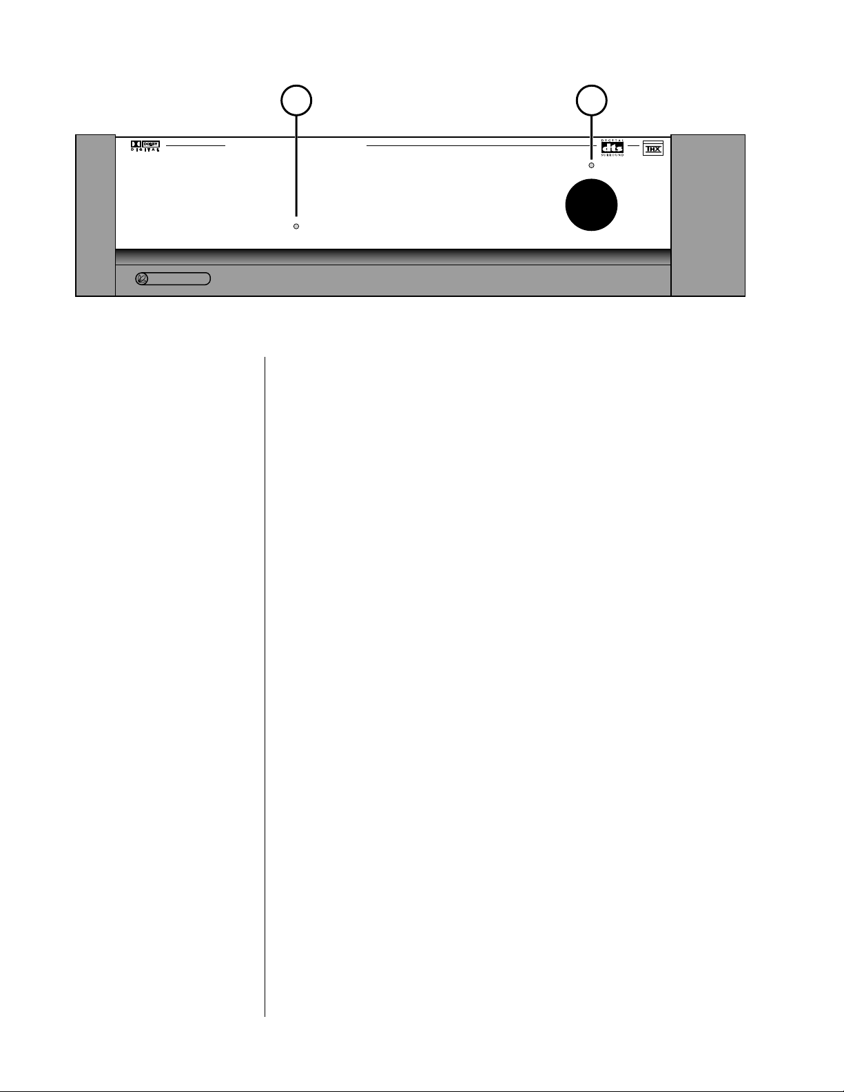
Front Panel
1 DIGITAL PROCESSING LED
This digital processing LED is normally completely off when an analog
source has been chosen, indicating that no digital signal processing is even
being attempted.
power
LUCASFIL
M
TM
®
If the PDSD cannot communicate with the PAV (due to a forgotten communications cable, for example), the digital processing LED will blink to indi-
cate that it is trying (but not succeeding) to communicate with the PAV.
The digital processing LED glows red when a digital signal has been se-
lected, but cannot be “locked” onto and used. (Example: the RF output of a
laserdisc player typically goes “dead” during scanning, chapter searches, and
side changes, interrupting the signal and preventing the Digital Surround
Decoder from doing what you have “asked” it to do.)
Finally, the digital processing LED glows amber when a digital signal has
both been chosen and is being successfully received, indicating that digital
processing is possible.
The Digital Surround Decoder will automatically and transparently decode
PCM (including a digital version of Dolby Pro Logic), Dolby Digital (for-
merly called AC-3), DTS Coherent Sound, and MPEG, switching to whatever
form of digital decoding and processing the signal requires. In any of these
cases, the digital processing LED will glow amber to indicate that the Digital
Surround Decoder is handling the signal for you.
If you wish to learn which of these digital processes is active, press the
status button on the remote control.
16
Page 17

2 POWER & POWER LED
Assuming that the Digital Surround Decoder’s power cord is connected to
AC power, pressing this latching power button connects the PDSD to the AC
mains and turns on the unit. When power is restored after an interruption,
the PDSD will be ready to operate (that is, it won’t be in standby), after a
few moments’ delay to allow its circuits to stabilize.
While the Digital Surround Decoder is in
power button is red. When the Digital Surround Decoder is ready to
operate (that is, when it is not in standby mode), this LED is amber. Natu-
standby, the LED above the
rally, when AC power is off, the LED is off.
17
Page 18
1 2 3 4 5
6
7
8
9
10
11
120VAC
60Hz
~
8
9
1110
digital inputs
6
digital inputs
3
21
32
54
17
digital
remote output
out
L
12
R
12
RL
RL
3
pav pass-through
3
rear
CS
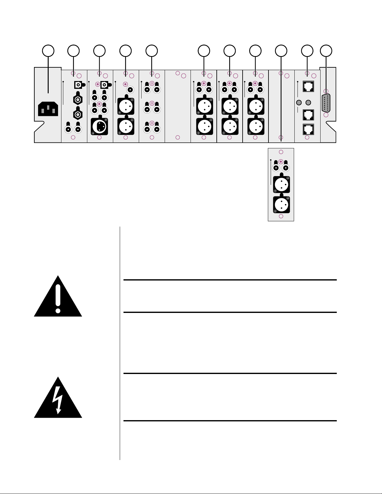
Rear Panel
center/sub main
surround
RL
L
12
R
front output
12
3
3
RL
L
12
R
surround output
12
3
3
CS
S
3
12
C
center/sub output
3
12
(optional)
12
2
12
1
aux. output
12
comm.
12
rem
on/off
slavemaster
control
3
3
Caution! Disconnect all associated equipment from the AC mains
BEFORE making any signal connections and applying power
to the Digital Surround Decoder.
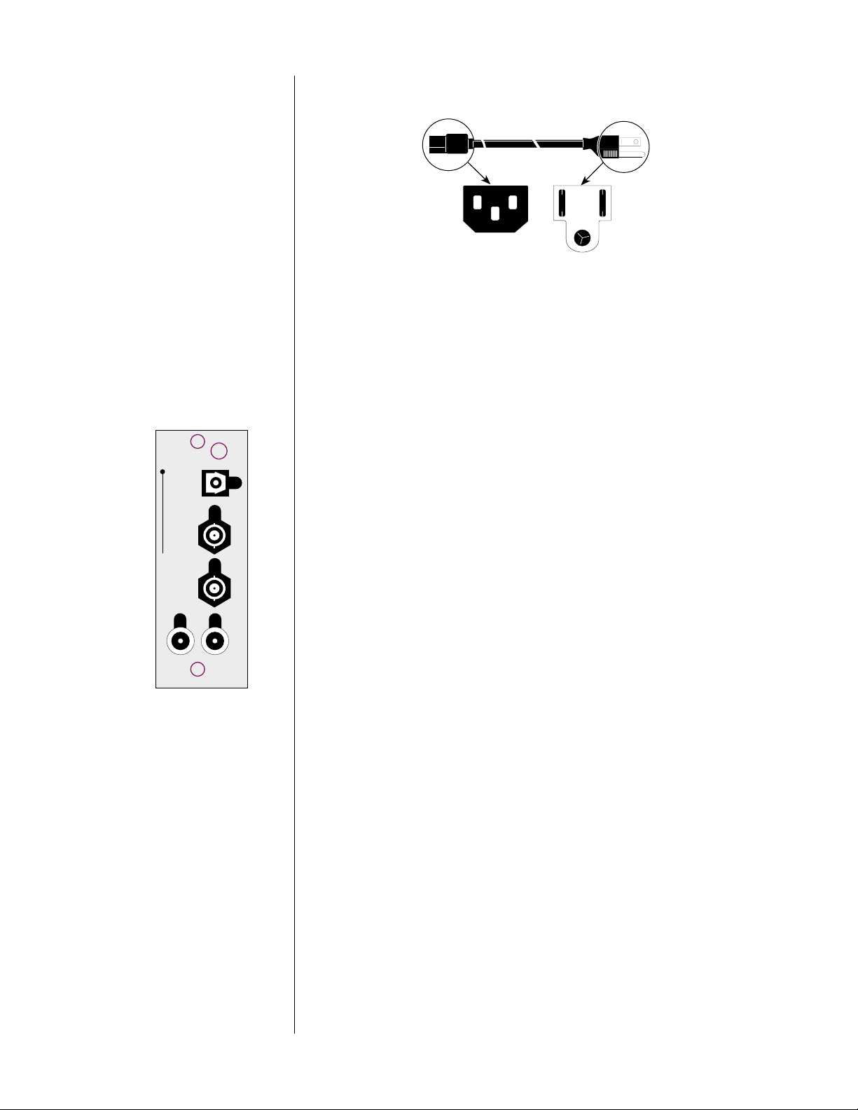
1 AC MAINS INPUT
This input accepts AC power from the AC mains (via the supplied AC
cable).
Warning! The Digital Surround Decoder is set internally for 100, 120, 220,
230, or 240VAC mains operation at either 50 or 60Hz. Make
sure that the label on the rear of the unit indicates the correct
AC operating voltage and frequency for your location before
connecting it to AC mains.
Connect the female end of this cable to the Digital Surround Decoder. Connect the male end of this cable to wall outlet.
18
Page 19
ac power cord polarity
7
8
9
digital inputs
1110
To Digital Surround
Decoder
132
1
3
To AC mains
1 = Line (hot)
2
2 = Neutral
3 = Earth ground
The power consumption of the Digital Surround Decoder is only about 100
watts, about the same as a light bulb. As such most people will leave it on
(or in standby) at all times. If you elect to turn the PDSD completely off
(rather than in placing it in standby), we advise waiting at least five seconds
between power cycles to allow the normal power-up sequence to complete
without interruption.
2 DIGITAL INPUTS 7-11
Please remember to make a note of what sources you connect to which
inputs. You will need to set up the relationships between front panel buttons and rear panel connectors later, in the setup menu system.
For now, you can connect any source to any compatible connector—just
keep a list of what-goes-where. (Just such a list is waiting for you later in
this manual. You might want to copy it in order to keep the original clean
for future use.)
Digital Input 7 accepts digital audio in the EIAJ optical (sometimes called
“Toslink”) digital interface standard from a digital satellite receiver, compact
disc, laserdisc, DVD or other digital source component. Connect the EIAJ
digital output of your source component to the EIAJ input of the Digital Surround Decoder using a high quality EIAJ optical cable.
Digital Inputs 8-9 accept digital audio conforming to the 75Ω S/PDIF digital
interface standard (via 75Ω cables equipped with BNC-type connectors)
from a digital satellite receiver, compact disc, laserdisc, DVD or other digital
source component. Connect the 75Ω S/PDI F output of your source compo-
nent to either of these inputs of the Digital Surround Decoder, using a high
quality 75Ω cable such as Madrigal MDC-2.
Digital Inputs 10-11 accept digital audio conforming to the 75Ω S/PDIF digital
interface standard (via cables equipped with RCA-type connectors) from a
digital satellite receiver, compact disc, laserdisc, DVD or other digital source
component. Connect the 75Ω S/PDIF output of your source component to
either of these inputs of the Digital Surround Decoder, using a high quality
75Ω cable such as Madrigal MDC-2.
If you have the optional internal RF demodulator installed in your Digital
Surround Decoder, Digital Input 11 is dedicated to that RF connection and
can only be used for that purpose. Connect the RF (Dolby Digital/AC-3)
output from your laserdisc player to Digital Input 11 if you have the internal
RF demodulator installed, using low-capacitance cable such as CZ Gel-2.
19
Page 20
3 DIGITAL INPUTS 1-6
Please remember to make a note of what sources you connect to which
1
32
inputs. You will need to set up the relationships between front panel buttons and rear panel connectors later, in the setup menu system. For now,
you can connect any source to any compatible connector—just keep a list
of what-goes-where. (Just such a list is waiting for you later in this manual.
You might want to copy it in order to keep the original clean for future
54
use.)
6
digital inputs
PUSH
3
21
Digital Input 1 accepts digital audio in the EIAJ optical (sometimes called
“Toslink”) digital interface standard from a digital satellite receiver, compact
disc, laserdisc, DVD or other digital source component. Connect the eiaj
digital output of your source component to the EIAJ input of the Digital Surround Decoder using a high quality EIAJ optical cable.
Digital Inputs 2-5 accept digital audio conforming to the 75Ω S/PDIF digital
interface standard (via cables equipped with RCA-type connectors) from a
digital satellite receiver, compact disc, laserdisc, DVD or other digital source
component. Connect the 75Ω S/PDIF output of your source component to
either of these inputs of the Digital Surround Decoder, using a high quality
75Ω cable such as Madrigal MDC-2.
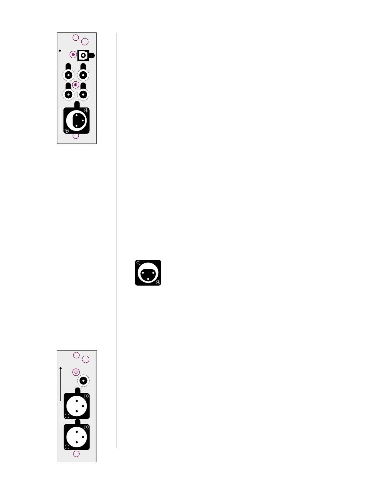
Digital Input 6 accepts digital audio in the professional 110Ω AES/EBU digital
interface standard (via a cable equipped with XLR-type connectors) from a
digital satellite receiver, compact disc, laserdisc, DVD or other digital source
component. Connect the AES/EBU digital output of your source component
to the AES/EBU input of the PDSD using a high quality 110Ω AES/EBU cable
such as Madrigal MDC-1.
The pin assignments of these AES/EBU XLR-type female input connectors are:
PUSH
21
3
Pin 1: Shield
Pin 2: Digital + (non-inverting)
Pin 3: Digital – (inverting)
Connector ground lug: chassis ground
20
digital
out
L
3
12
R
remote output
3
12
These pin assignments are consistent with the standards adopted by the
Audio Engineering Society and the European Broadcast Union. Refer to the
operating manuals of your digital sources to verify that the pin assignments
of their output connectors correspond to the Digital Surround Decoder. If
not, wire the cables so that the appropriate output pin connects to the
equivalent input pin.
4 REMOTE OUTPUT (ANALOG & DIGITAL)
By connecting the balanced (analog) remote outputs in this module to the
bal/aux input on the PAV, all PCM (normal digital, not Dolby Digital nor
DTS) sources connected directly to the Digital Surround Decoder will be
available for distribution to either the PAV’s remote zone or its record path.
When you select (on the PAV) such a digital source for either the remote
zone
or the record path, the PDSD will pass that digital signal to this mod-
ule, where it will be converted to analog and forwarded to the PAV, which
will in turn send the signal out its appropriate analog outputs. Note that
sources such as AC-3 and DTS are not available at this twochannel analog output. (They are, however, available in their original
digital form at the digital output; see below.)
Page 21
By looping the digital sources back through the PAV in this manner, the PAV
can distribute either analog or digital sources to the remote zone or record
path without your having to think about the details of where the signal originates.
The remote output module also includes a S/PDIF (on an RCA) digital output,
should you wish to distribute a digital source in its original, unprocessed
digital form. For example, if you had another multichannel system elsewhere
in the home, you could forward a Dolby Digital bitstream to the other system from this one—running a single digital cable instead of five or six analog cables for surround sound applications.
Note: The digital remote output can forward only unprocessed
digital sources to another zone or system. By their nature,
analog sources would be excluded from this method of
distribution unless they were first converted to digital form.
5 PAV PASS-THROUGH
You must connect the six main output channels of the PAV to their corresponding pav pass-through inputs on the Digital Surround Decoder. When
listening to an analog source connected to the PAV, any signal processing
will be done in the analog domain (in the PAV), and simply forwarded to
the amplifiers through the PDSD. In this way, you can continue to enjoy the
performance of the PAV with analog sources even while adding the capabilities of the Digital Surround Decoder for digital sources.
RL
L
12
R
front output
12
One benefit to this approach is that all six channels of the PAV are con-
verted to balanced signals prior to being sent to the power amplifiers (contrasted with only two channels of the PAV being balanced when used by
itself). Balanced interconnection between the PDSD and the power amplifiers can result in lower noise and better subjective performance, particularly
when long runs of cable are required.
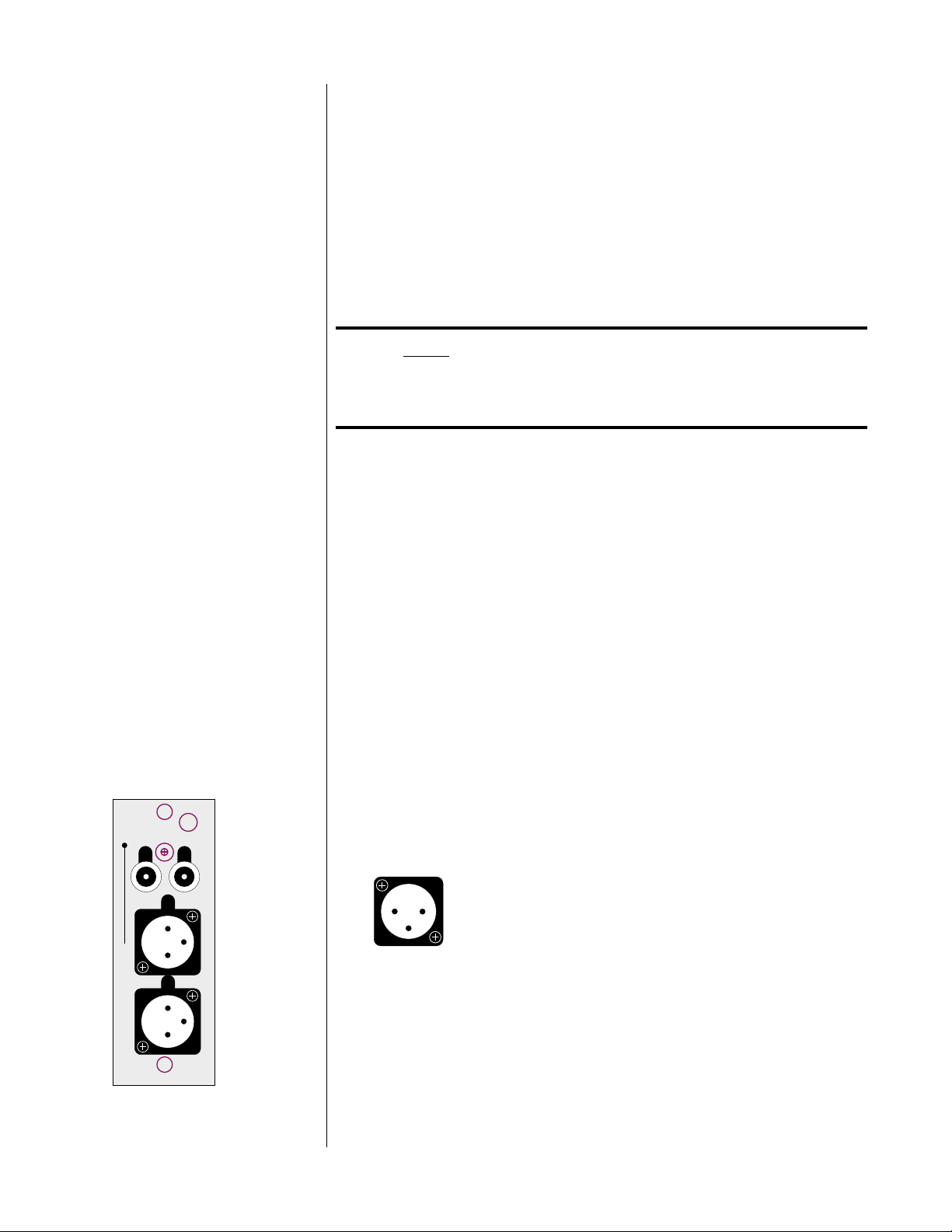
6 FRONT OUTPUTS
The pin assignments of these XLR-type male outputs conform to the international AES standard, and are as follows:
Pin 1: Signal ground
12
3
3
Pin 2: Signal + (non-inverting)
Pin 3: Signal – (inverting)
Connector ground lug: chassis ground
Refer to your power amplifier’s operating manual to verify that the pin assignments of its input connectors correspond to the Digital Surround De-
3
coder. If not, wire the cable so that the appropriate output pin connects to
the equivalent input pin, or reverse the leads of both your speaker cables to
“reverse the reversal” and restore correct polarity.
High quality single-ended outputs are also provided for compatibility with
power amplifiers lacking balanced inputs.
21
Page 22
RL
Connect the left-front and right-front outputs of the Digital Surround Decoder to the corresponding inputs on your power amplifier(s).
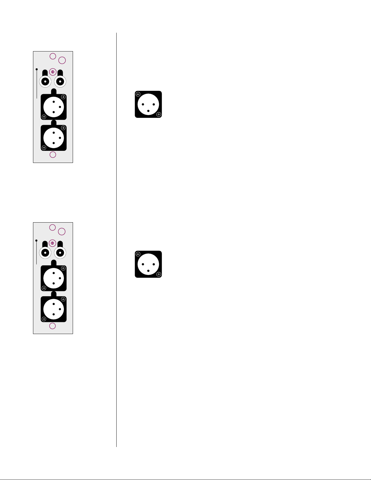
7 SURROUND OUTPUTS
The pin assignments of these XLR-type male outputs conform to the international AES standard, and are as follows:
L
3
12
R
surround output
center/sub output
3
12
CS
S
3
12
C
3
12
Pin 1: Signal ground
12
3
Pin 2: Signal + (non-inverting)
Pin 3: Signal – (inverting)
Connector ground lug: chassis ground
Refer to your power amplifier’s operating manual to verify that the pin assignments of its input connectors correspond to the Digital Surround Decoder. If not, wire the cable so that the appropriate output pin connects to
the equivalent input pin, or reverse the leads of both your speaker cables to
“reverse the reversal” and restore correct polarity.
High quality single-ended outputs are also provided for compatibility with
power amplifiers lacking balanced inputs.
Connect the left-surround and right-surround outputs of the Digital Surround Decoder to the corresponding inputs on your power amplifier(s).
8 CENTER/SUB OUTPUTS
The pin assignments of these XLR-type male outputs conform to the international AES standard, and are as follows:
Pin 1: Signal ground
12
3
Pin 2: Signal + (non-inverting)
Pin 3: Signal – (inverting)
Connector ground lug: chassis ground
Refer to your power amplifier’s operating manual to verify that the pin assignments of its input connectors correspond to the Digital Surround Decoder. If not, wire the cable so that the appropriate output pin connects to
the equivalent input pin, or reverse the leads of both your speaker cables to
“reverse the reversal” and restore correct polarity.
22
High quality single-ended outputs are also provided for compatibility with
power amplifiers lacking balanced inputs.
Connect the center and subwoofer outputs of the Digital Surround Decoder
to the corresponding inputs on your power amplifier(s).
9 AUX OUTPUT (OPTIONAL)
An additional two output channels may be added to the Digital Surround
Decoder if desired. These channels are most commonly used for side
speakers in addition to the rear speakers, though they can also be used in
conjunction with Dual Drive™ surrounds, or to support stereo subwoofers.
The “sides+rears” 7.1 channel arrangement is particularly beneficial in large
rooms, as it ensures more uniform surround coverage throughout the listening area. Your dealer can install and set up these additional channels for
you should you need them.
Page 23
Caution! There are no user-serviceable parts inside the Proceed Digital
Surround Decoder. Please contact your dealer for assistance
if you need to swap modules in order to install this or any
other option.
The pin assignments of these XLR-type male outputs conform to the international AES standard, and are as follows:
Pin 1: Signal ground
12
3
Pin 2: Signal + (non-inverting)
Pin 3: Signal – (inverting)
Connector ground lug: chassis ground
Refer to your power amplifier’s operating manual to verify that the pin assignments of its input connectors correspond to the Digital Surround Decoder. If not, wire the cable so that the appropriate output pin connects to
the equivalent input pin, or reverse the leads of both your speaker cables to
“reverse the reversal” and restore correct polarity.
High quality single-ended outputs are also provided for compatibility with
power amplifiers lacking balanced inputs.
Connect the left and right auxiliary outputs of the Digital Surround Decoder to the appropriate inputs on your power amplifier(s).
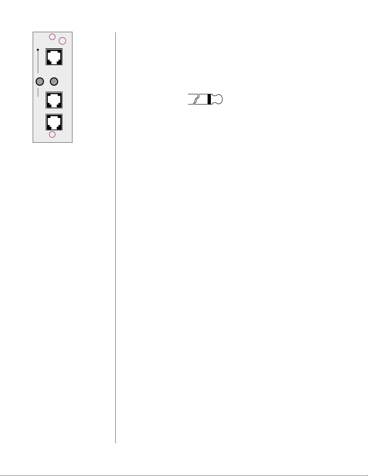
10 CONTROL/COMMUNICATIONS
The Digital Surround Decoder provides for robust communications between components using this module. The uppermost comm. port is reserved for communications with the PAV, which provides the user interface
(among other things) for the PDSD. Connect a modular RJ-11 cable (supplied with the Digital Surround Decoder) between this port and the corresponding port on the PAV.
Important! If you are using a PAV that was built before early 1997, your
dealer will need to perform a simple hardware update to your
PAV prior to being able to use it with the Digital Surround
Decoder. This update will provide the necessary physical
connection at the PAV end.
If your PAV already has the communication port next to its
power switch on the rear panel, then your dealer will need
only to update its EPROM with the one that came with the
PDSD for it to work seamlessly with the Digital Surround
Decoder.
There are no user-serviceable parts inside the Proceed Digital
Surround Decoder. Please contact your dealer for assistance
if you need to swap modules in order to install this or any
other option.
23
Page 24
12
control
.
rem
on/off
slave
master comm
Each of the two remote on/off triggers can be configured by your installer
to provide either 5V or 12V trigger signals, either in response to the PAV/
PDSD system coming out of standby into operate, or in response to an independent IR command. The tip polarity for each of these triggers is as
shown below:
+–
5-12 volts @ less
than 100 mA
These triggers provide some degree of control and automation over products that lack more sophisticated communications capabilities. For example,
you could have one of these triggers toggle your amplifiers on and off according to the operational status of the PAV/PDSD combination, while the other
served to lower the screen for your projection television when a particular IR
command was received.
The remaining two communications ports at the bottom of the module
provide for sophisticated inter-component communications between the
PAV/PDSD system and future Proceed products. Your dealer can assist you
in taking advantage of these advanced features.
11 DB-15 CONNECTOR
This DB-15 connector is reserved for future applications. (After all, your
Digital Surround Decoder will be in your system a long, long time….)
24
Page 25

Using The Menu System
The PAV/PDSD combination uses a new, dynamically-updated menu system that
operates more intelligently than most such systems. For example, when configuring inputs, the menu options change according to the selections you have made.
In effect, the PAV/PDSD system only asks you for relevant information, thereby
minimizing possible confusion.
Four buttons on the remote control are used to navigate through its extensive on
screen menu system:
note to PAV owners: The menu navigation system used in the PAV/PDSD system is a
bit different than the one you used on the PAV alone (we think
it’s improved), and it may take you a few minutes to adjust to
the new way of doing things. Please take a moment to review
this section before using the menus in your new system.
to enter the menu system Pressing menu once will display the PAV/PDSD Main Menu of the on screen
menu system. Note that the display on the PAV itself turns off when you enter the
on screen menu system (to encourage you to look on screen, where the important information is). The main menu provides access to the three major function
areas of the menu system:
menu, enter, volume +, volume –.
•The Operate Menu is where user preferences are set. These items
tailor the way the system interacts with you to suit your personal
preferences, but do not effect the performance of the system in
any substantive way.
•The Setup Menu is normally used only by the installer at the time
of the initial system setup. Many of the items in this menu have
significant impact on the actual performance and functionality of
the system, and should be changed only by those who have taken
the time to learn the way the system works.
•The Custom Menu is also used by your installer to customize your
system even further. Whereas every system must be properly setup
using the Setup Menu, the items in the Custom Menu are more
rarely needed—as with systems that employ home automation, or
to resolve potential infrared command conflicts between the PAV/
PDSD and other components in your system. Once again, the items
contained within this menu should be used/changed only by
those who have taken the time to learn the way the system works
(which you can do by reading this manual thoroughly, if you
wish).
•The About… menu describes the various parts of the operating
software being used by the PAV and the PDSD, and is used only as
a reference should you ever need to call for technical support (so
we can be certain that we are looking at the same operating software you are looking at when you use your system). You might
want to copy these (somewhat arcane) numbers down in the Yo u r
Settings
section of this manual for future reference.
25
Page 26

to exit the menu system From the PAV/PDSD Main Menu, pressing menu again will exit the menu system.
Since pressing menu (once within the menu system) also cancels current actions and
moves you up one level in the menu hierarchy, you can leave the menu system by
pressing menu repeatedly—no matter how “deep” you are within the system.
to select a menu item Once within the menu system, an arrow indicates the currently-selected item on
the menu. This arrow can be thought of as the “select-it” cursor. It can be moved
up or down with the volume + and volume – buttons.
to change a menu item Having selected the item you wish to work with, pressing enter will allow you to
work with it.
When changing the item in question can be displayed on the current menu
screen, the “select-it” arrow cursor changes to a “change-it” x cursor. When the
“change-it” cursor is displayed next to an item, using the volume +/– buttons will
now increment or decrement the value of the item in question.
Some of the changes called for by a particular menu item require more space
than is available at the end of the current line. In this case, pressing enter still allows you to work with the item in question, by taking you to the next-lower
screen in the hierarchy. A case in point: there are several display preferences you
can modify to suit your needs, so pressing enter when the cursor is next to dis-
play prefs
takes you to another screen that lists them in more detail.
to save changes Having changed/edited an item, you can save your changes by pressing enter
again. This both saves the change and returns you to where you were just prior
to making the change (either changing back to the “select-it” cursor or moving up
one level to the previous menu, as appropriate).
to “escape” or “cancel”
without saving any changes
If you wish to cancel any changes you might have made, exiting the currentlymodifiable menu item without saving any changes, simply press menu. This acts
like the Escape key or Cancel button on a computer, and will return you to
where you were just prior to making the change you decided not to save.
front panel equivalents In a pinch, you may need to navigate the menu system as outlined above, but
without using the remote control. (An example would be when teaching the
learning remote new commands, since it cannot both issue and learn commands
at the same time.) You can do this by pressing and holding the recall button on
the front panel for about three seconds; this serves as a front panel equivalent of
menu on the remote. Once in the menu system, the recall button on the front
panel can be clicked (without holding it each time), and the menu will respond
as though the menu button had been pushed.
Once in the menu system, the front panel equivalents are:
•menu =recall (to cancel an action, or move up a level)
• standby = enter (to save a change and/or move up a level)
• volume + = volume + (to move up in a menu, or increase a value)
• volume – = volume – (to move down in a menu, or decrease a value)
26
As with the menu button on the remote control, clicking recall on the front
panel when the main menu is displayed will exit the menu system.
Page 27
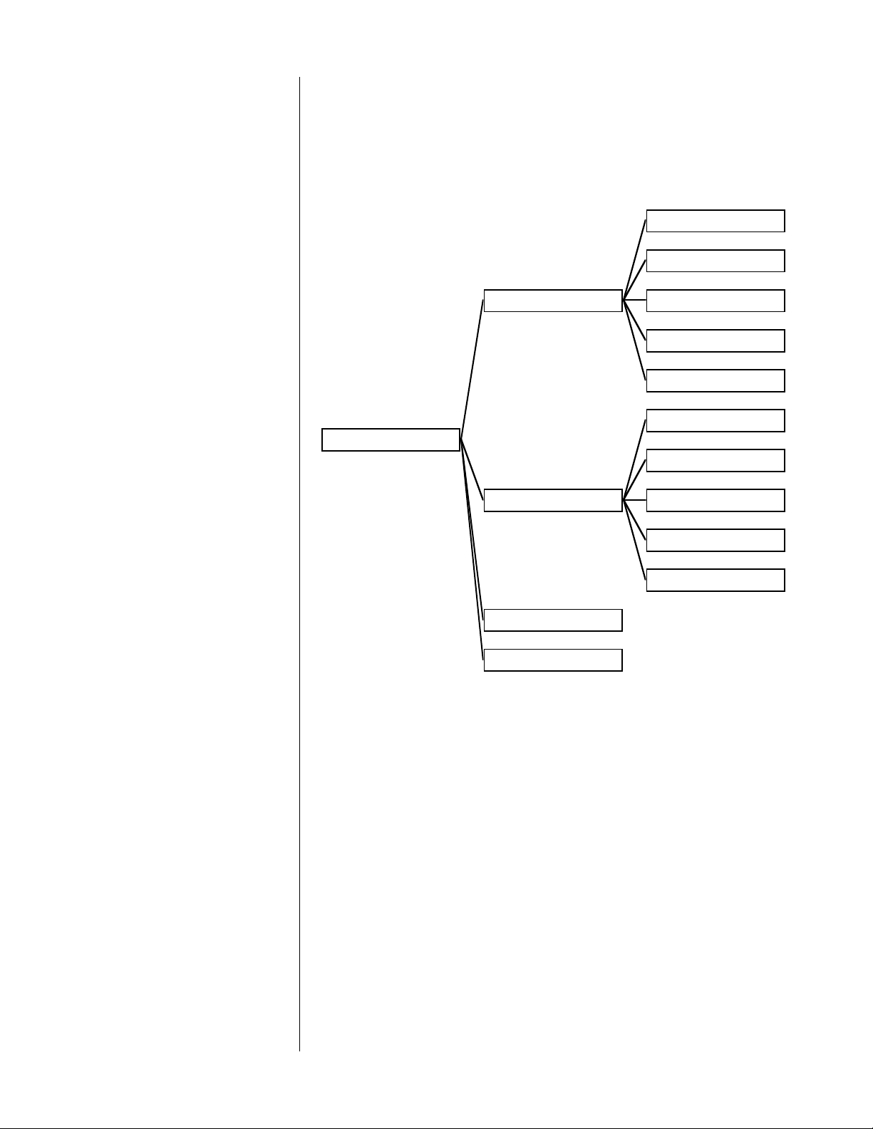
The Operate Menu
E
S
E
N
DISPLAY POSITION
STATUS PREFERENCE
OPERATE
DISPLAY PREFERENC
VOLUME PREFERENC
AUTO MIGRATION: O
SETUP: UNLOCKED
TIMEOUT: 3 SECOND
TEXT: FRINGE
BACKGROUND: BLUE
DISPLAY: ABSOLUTE
SPEED: FAST
MUTE LEVEL: -40
MAX VOLUME: 125
DIALOG NORM: ON
The Operate Menu gives you control over the way the system displays information and the details of how volume-related functions are handled. It also allows
you to lock the setup settings (preventing access to the Setup and
Custom Menus) to minimize the chance of unwanted tampering with settings
that alter the way the system performs. In effect, the Operate Menu provides access to non-essential, preferential settings.
display position The displayed position of the on screen messages for volume changes, surround
mode changes, etc., can be moved up or down to suit the needs of your system.
This flexibility allows you to place your PAV/PDSD’s on screen information where
it won’t conflict with other on screen information. As an example, you may want
to place the on screen display in the black area under letterboxed movies.
status preferences The PAV/PDSD system can display a wealth of information about the source and
nature of the signal being listened to, any signal processing going on, and other
details about the operation of the system. By default, all of this information is displayed when you press the status button on the remote control. However, if you
27
Page 28

find that this display is more than you need or want, you can turn off individual
N
lines of the display in this submenu.
STATUS PREFERENCE
AUDIO IN INFO: ON
VIDEO IN INFO: ON
FORMAT INFO: ON
MODE INFO: ON
THX INFO: ON
SUB INFO: ON
VOLUME INFO: ON
MIGRATION INFO: O
The information that can be displayed includes:
• audio in info (the source providing the sound)
• video in info (the source providing the picture)
• format info (the nature of the incoming signal)
• mode info (the surround mode processing being used)
• THX info (whether THX processing is engaged)
• sub info (whether one or more subwoofers is active)
• volume info (the current volume setting)
• migration info (whether automatic or manual migration is active)
Simply move the cursor to the status preferences line and press enter. Then
move the cursor to whichever item you prefer to leave off, press enter, and turn it
off with the volume ± buttons; then press enter again to save your change. You
may, of course, turn anything back on at a later time by repeating the process.
display timeout This setting controls the duration of these on screen messages generated by the
PAV/PDSD when you change something. (Remember that you can disable the on
screen display entirely using the on screen button on the remote control.) You can
set it for 1, 2, 3, 4, or 5 seconds, according to your preference.
display of text On screen messages are normally displayed with a black fringe around their
white letters when superimposed on live video signals. This display method is
easy on the eyes and almost always easily read. However, you can opt to have the
on screen messages displayed within a black box to ensure legibility even against
extremely bright backgrounds, when white letters might otherwise be difficult to
read.
display background The default background color for the screen when lacking a live video signal, or
when in the menu system, is blue. This blue screen serves as a reminder that
your television is on when in fact you may prefer to turn it off. However, some
may prefer to leave their projection televisions on in order to keep them warmed
up and ready to use, in which case a black screen might be more desirable. (A
black screen would facilitate listening to music in a darkened room, for example,
and saves unnecessary wear on the blue gun of the projector.) This menu item
allows you to choose the best mode for your system, either blue or black.
volume display You have the option of displaying your volume settings either of two ways:
• absolute—on a scale of 0 (no sound) to 125 (extremely loud); or
• relative—on a scale which is measured plus or minus relative to
the calibrated reference volume (established during calibration).
As an example, if your calibrated reference level is 91, the display would read 0 in
the relative mode when it would read 91 in the absolute mode. Most people find
absolute more intuitive, while some people find relative more informative. (For
example, those who have made many recordings, and are accustomed to VU
meters that read ± relative to a calibrated zero point may prefer the relative set-
ting.)
28
Page 29

volume speed You may select either slow or fast response for the rate at which the volume
change accelerates when pressing and holding the volume +/– keys. I n all cases,
single taps of the volume keys result in single incremental steps in volume. The
volume speed chosen affects the amount of time it takes to reach maximum
speed while holding the volume +/– button down.
volume mute level The magnitude of volume reduction introduced by pressing the mute key is user-
definable in increments of 5, from -5 to -120. The factory preset is for -40 (-20
dB). (Remember that each step in the volume control represents about 1⁄2 dB; thus
a change of “5” represents a 2.5 dB change in volume.)
maximum volume You may set a maximum volume allowed for your system to minimize the oppor-
tunity for damage, either to your system or to better relations with your neighbors. Simply choose the maximum volume setting you would like to be able to
use and save the change (by pressing enter, as always). If you decide to change it
again, simply revisit this menu item and reset it.
dialog normalization Digital audio has a clearly-defined maximum recordable volume. In some movies,
the dialog may exist fairly close to this maximum volume, especially if the movie
does not have of loud noises that need occasionally to overshadow the dialog.
Other movies are full of explosions and other effects that must be much louder
than the dialog in order to achieve their desired effect. Thus the level at which
dialog occurs within the overall digital dynamic range may vary significantly, requiring volume changes from one source to the next, or one movie to the next.
auto migration As shipped from the factory, the PAV/PDSD system automatically tries to give you
forced/manual migration
Dialog normalization takes advantage of the fact that Dolby Digital soundtracks
are supposed to include information on the relative volume of the dialog. Using
this information, we can automate this volume adjustment for you so that the dialog appears at approximately the same volume all the time. (Of course, this assumes that the movie’s Dolby Digital soundtrack includes accurate information
regarding dialog level.) This automatic volume change may be defeated if you
prefer to handle such things yourself.
your “preferred” audio connection, whenever it is available. Thus if you have a
Dolby Digital RF connection as your “first choice,” followed by a normal digital
connection, followed by the analog connection specified in your set source but-
ton
screen for laserdisc, when you first select the input the system will start at
the beginning of your list and work its way down your list until it finds a valid
signal.
If for some reason you prefer to handle such changes manually, you can turn off
automatic migration in this section of the operate menu.
Additionally, you can always temporarily engage manual migration simply by
pushing the same input button repeatedly (which cycles through the connections
associated with that button). As soon as you select any other input button, auto-
matic migration
will re-engage.
setup: locked/unlocked Once the PAV/PDSD is completely setup, calibrated and ready to go, you may
want to change this setting from setup: unlocked to setup: locked to make it
29
Page 30

more difficult to accidently disturb the carefully calibrated settings in the Setup
and Custom Menus. Toggle the lock on and off by moving the “select-it” cursor to
this item, changing to the “change-it” cursor by pressing enter, and pressing either
volume + or volume – (with only two settings, either plus or minus will work).
Then save your change by pressing enter.
30
Page 31

The Setup Menu
N
SET SOURCE BUTTON
CD 1
CD 2
TAPE 1
TAPE 2
BAL/AUX
TUNER
VCR 1
VCR 2
SETUP
SET SPEAKERS
MODE DEFAULTS
LD
TV/AUX
SET CONFIGURATIO
SET DISTANCE
SET LEVELS
BASS LEVEL MANAGE
***ENABLED***
DISCRETE
PRO LOGIC
STEREO SRND
MONO SRND
2-CH/SRND OFF
MONO
31
Page 32

As you might surmise from the menu tree shown above, the Setup Menu is
where you define what it is you are using with your PAV/PDSD system, and how
you want it to work for you.
To take a common but surprisingly complex example, imagine:
• that you have a laserdisc player that has an RF Dolby Digital (AC-
3) output, a digital output, and analog outputs;
• that you usually listen to it in THX cinema mode, whether using
discrete digital soundtracks or Dolby pro logic soundtracks;
• and that you prefer to use a subwoofer for movies for the extra
impact, but prefer not to use it when listening to music.
The
setup menu is where you “explain” all this to the PAV/PDSD system, so that
all you have to do when you want to watch a laserdisc is press the button labeled: laserdisc. The system can easily do everything else for you. It even figures
out which of the three connections (AC-3, normal digital, and analog) it needs to
use without you having to read the fine print on the back of the laserdisc jacket.
We’ll take each of the submenus in turn.
set source buttons Each of the buttons on the front of the PAV may be associated with any of the
audio (or video!) connectors on the rear of both the PAV and the Digital Surround
Decoder. In fact, each button can be associated with a maximum of three audio
connections (the AC-3 RF input if you have the RF demodulator, plus a digital in-
put, plus a set of analog inputs on the PAV) and one video connection.
example: setting up
a cd transport
The reason for this extraordinary flexibility is that we want you to be able to use
the button that makes sense for each component, regardless of the type of con-
nector it may require. By manually associating whatever connector you need to
use with the button you wan t to use, you can make the system work the way
you want it to work.
Moreover, we feel the system should handle the day-to-day details of sorting out
RF AC-3, digital and analog software for you, rather than you having to read the
fine print on each disc you own. By assigning more than one connector to a
given button (as needed), the system can search for a usable signal rather than
making you do it,. It performs this task according to a list you give it during
setup.
Thus, we give you a scrolling list of all ten input buttons, and give you the opportunity to tell the PAV/PDSD which connectors you would like it to use when
you press that button. Your first connector is also your “first choice,” the priority
connection; second choice is second priority; and third connector selection is the
“last resort.” (That is, when there is nothing to listen to on the first and second
choices.)
A couple examples will help. With a simple CD transport, you might set up your
default selections as follows:
32
Page 33

1
NAME: CD 1
D
O
TYPE: AUDIO
MODE: STEREO SRN
DEFINE BUTTON CD
renaming source buttons Your first decision: would you like the on screen display to identify your CD
RECORD DEVICE: N
AUDIO CONNECTORS:
AUDIO: DIGITAL
1: DIGITAL, DIG 6
CONN: DIG 6
transport with something more specific than a generic cd1 name? If so, enter the
characters one at a time, up to a maximum length of eight.
1 MOVE THE SELECT-IT CURSOR BESIDE “NAME:” AND PRESS ENTER TO
ALLOW FOR CHANGES TO BE MADE.
A blinking box indicates the first available space for your new name. If you
need to move it, press any PAV/PDSD button on the remote other than the
usual four you use for navigating menus. The path button will do nicely,
and is conveniently nearby on the remote control.
2 USE THE VOLUME +/– BUTTONS TO SCROLL THROUGH THE LIST OF
AVAILABLE CHARACTERS UNTIL YOU SEE THE ONE YOU NEED
This system works similarly to the titling feature on many camcorders. Available characters include the alphabet, all numbers, and various punctuation
marks, including blank spaces for separating words.
3 MOVE ON TO THE NEXT CHARACTER BY PRESSING ANY PAV/PDSD
BUTTON ON THE REMOTE
OTHER THAN
THE FOUR YOU USE FOR
NAVIGATING MENUS.
As before, the path button will do nicely, and is conveniently nearby. Pressing a button on the PAV/PDSD remote control that has nothing to do with
the PAV/PDSD (a transport button, for example) will have no effect.
4 REPEAT UNTIL YOU HAVE THE ON SCREEN NAME YOU WANT THE SYSTEM
TO USE; WHEN DONE, PRESS ENTER TO SAVE THE NAME
As always, enter saves a change. If you get part way through the process of
changing the name (or any other adjustment in the menu system) and
change your mind, you can cancel your changes by pressing menu. This
will leave the name unchanged from what it had been before you started.
defining the input type Next, you need to decide what kind of source you plan to use with this particu-
lar button: audio only, audio/video, or none at all. In the case of setting up your
CD transport, this is pretty simple (and we’ll keep it that way for now).
33
Page 34

1 MOVE TO THE “TYPE:” ITEM IN THE MENU, PRESS THE ENTER BUTTON,
AND USE THE VOLUME +/– BUTTONS TO CHOOSE “AUDIO”; PRESS ENTER
AGAIN TO SAVE THE CHANGE
In reality, this is how the unit is shipped from the factory anyway, but while
you are here you may as well see what your options are by using the vol-
ume +/–
buttons to cycle through the choices. Choose audio before you
finish up, or press menu to cancel without making any changes.
Had you chosen
a/v rather than audio, the subsequent menu would have been
updated to include video-related setup items. Since you don’t need them here,
they are not displayed. (We will get to that when we run through setting up a
laserdisc player, a bit later.)
choosing a surround mode The PAV/PDSD system also lets you choose a default surround mode that will
automatically be chosen whenever you select this source. For example, if you find
yourself using the stereo surround mode for most of your music listening, you
can automate your preferences.
Note: These “surround modes” refer to what the system does when
given a two-channel input signal, whether analog or digital.
Pro Logic is one such two-channel signal as it enters the
Digital Surround Decoder, one that has been encoded to
provide multiple channels when properly decoded.
Discrete multichannel signals (such as those provided by
Dolby Digital, DTS, or MPEG/Musicam) will override these
surround preferences and always be reproduced in their
intended multichannel forms.
34
If you already know what your preference is, you might as well program it in
now. If you aren’t sure, we suggest leaving the default surround mode for your CD
transport as stereo surround for now. You can always change it later.
1 MOVE TO THE “MODE:” ITEM IN THE MENU, PRESS THE ENTER BUTTON,
AND USE THE VOLUME +/– BUTTONS TO REVIEW YOUR AVAILABLE
SURROUND MODES; CHOOSE THE ONE YOU WANT AUTOMATICALLY
ENGAGED; PRESS ENTER AGAIN TO SAVE THE CHANGE
Of course, during day to day operation, you can easily override this default
selection by simply pressing the mode button on either the remote control
or the front panel at any time. Doing so will cycle you through the available
(two-channel) surround modes.
is it a recording device? If this component were capable of recording (a CD-R, tape deck, VCR, etc.), and
assuming you wanted to make recordings through the system, you would need to
make another connection to provide for making those recordings. Specifically, you
would need to use one of the record outputs on the PAV to feed the recording
device a signal to be recorded.
Moreover, the system needs to know which sources are hooked up in this way to
ensure that you do not accidently send a source back to itself to be recorded—a
Page 35

situation that can produce unpleasant and even speaker-threatening feedback
loops. For these reasons, we need to let the system know which of our sources
are connected to a record output (any record output).
1 MOVE TO THE “REC OUT:” ITEM IN THE MENU, PRESS THE ENTER BUTTON,
AND USE THE VOLUME +/– BUTTONS TO INFORM THE SYSTEM WHETHER
A RECORD OUTPUT IS BEING USED WITH THIS SOURCE COMPONENT;
PRESS ENTER AGAIN TO SAVE THE CHANGE
Your choices are simple enough:
yes and no. For a CD transport, you’ll
probalby leave it at no.
how many input connectors? How many physical connections does this component require? (A stereo pair of
analog signals is considered “one connection” for the purposes of this discussion.) In the case of a CD transport, the answer is easy. All you have is a digital
output to accommodate, so the answer is one. A laserdisc player is the most complicated, since it might have three sets of signals: RF Dolby Digital (AC-3), normal
(S/PDIF) digital, and a pair of analog outputs for the occasional old disc that has
only analog soundtracks. (This would be a pretty old disc, but they do exist.…) In
this extreme case, you would need three sets of connections. We’ll come back to
laserdisc later—for now, let’s stick with your CD transport, with its single connection.
1 MOVE TO THE “AUDIO CONNECTORS:” ITEM IN THE MENU, PRESS THE
ENTER BUTTON, AND USE THE VOLUME +/– BUTTONS TO INFORM THE
SYSTEM HOW MANY CONNECTIONS ARE NEEDED; PRESS ENTER AGAIN
TO SAVE THE CHANGE
As you work with the menu system a bit, the habit of pressing enter to
work with an item and then pressing it again to save your work becomes
second nature.
defining input connectors Once the PAV/PDSD system knows how many connections you need for this par-
ticular component, it updates its menu to provide for defining those connections.
With only a single digital connection (for your CD transport), this is pretty simple.
Just tell the system which digital input connector you used when you hooked up
the CD transport.
1: DIGITAL, DIG 6
AUDIO: DIGITAL
CONN: DIG 6
1 MOVE TO THE “1:” ITEM IN THE MENU, PRESS THE ENTER BUTTON
Since there are actually two things the system needs to know, and they
would not have fit on a single line without confusion, you will be taken to
the next-lower screen, which shows two items: audio and conn (short for
“connector”).
2 PRESS ENTER AGAIN TO WORK WITH “AUDIO:” AND CYCLE THROUGH
YOUR OPTIONS WITH THE VOLUME BUTTONS; CHOOSE DIGITAL AND
PRESS ENTER TO SAVE
Once again, this is the factory default setting. Were you setting up a CD
player that had only analog outputs, though, you would probably want to
change this to analog and use a set of analog connectors on the PAV (cd1
would be a good choice to avoid confusion).
35
Page 36

3 MOVE TO “CONN:” WITH THE VOLUME BUTTONS, PRESS ENTER TO WORK
O
F
WITH IT, AND CYCLE THROUGH THE LIST OF CONNECTORS UNTIL YOU
SEE THE ONE YOU USED; PRESS ENTER TO SAVE THIS SETTING, AND
MENU TO RETURN TO THE PREVIOUS/HIGHER MENU
As mentioned during the Quick Start for CD, you can connect any source
component to any appropriate connector, and then simply tell the system
what you have done. It is helpful to have written down what components
are connected where during initial hookup, so you don’t have to try to peer
around the back of the system with a flashlight later. A form for this purpose is included at the back of this manual. (Use a pencil, in case something changes in the future.)
example: setting up
a laserdisc player
A laserdisc player, as mentioned earlier, has several more connections that need to
be handled than a simple CD transport. We will run through these additional settings next, without repeating the sections that remain the same.
NAME: LD
TYPE: A/V
CONNECTOR: LD
VID: LD COMP
TYPE: COMP
MODE: PRO LOGIC
RECORD DEVICE: N
AUDIO CONNECTORS:
DEFINE BUTTON LD
AUDIO: DIGITAL
1: DIGITAL, DIG 11(R
CONN: DIG 11 (RF)
36
AUDIO: DIGITAL
2: DIGITAL, DIG 5
CONN: DIG 5
AUDIO: ANALOG
3: ANALOG, LASER
CONN: LD
INPUT OFFSET: -6
(As a reminder, the path to the define button ld menu shown above is main
menu/setup/set source buttons/ld
—but you can get there faster by pressing and
holding the laserdisc button for several seconds.)
Page 37

defining the video connection The appropriate type: from the define button ld menu this time is a/v. After hav-
ing selected it (or in this case when you reach this screen, since it is selected as
a factory default for the laserdisc button), you will see an additional item immediately below type. The vid: item establishes which video connector you wish to
associate with this button (in this case, laserdisc).
1 MOVE TO THE “VID:” ITEM IN THE MENU, PRESS THE ENTER BUTTON
Since there are actually two things the system needs to know, and they
would not have fit on a single line without confusion, you will be taken to
the next-lower screen, which shows two items:
connector and type.
2 PRESS ENTER AGAIN TO WORK WITH “CONNECTOR :” AND CYCLE
THROUGH YOUR OPTIONS WITH THE VOLUME BUTTONS; CHOOSE
“LASERDISC” AND PRESS ENTER TO SAVE
Once again, this is the factory default setting, so you probably don’t actually
have to do anything.
3 MOVE TO “TYPE:” WITH THE VOLUME BUTTONS, PRESS ENTER TO WORK
WITH IT, AND CHOOSE EITHER COMP OR S-VIDEO ACCORDING TO
WHAT YOU ACTUALLY USED; PRESS ENTER TO SAVE THIS SETTING
We strongly recommend choosing either composite or S-video and using
your choice throughout the system. This greatly simplifies the operation of
the system (since you no longer have to be switching inputs on your television every time you switch sources).
defining multiple
audio connections
Now the system knows which video connector to look at when you press
laserdisc. Next, let’s move to the number of audio connectors. (You can change
the surround mode default along the way if you like… but you already know
how to do that.)
The laserdisc has the greatest potential for confusion, having as it does three pos-
sible connections that may be needed. In addition, multiple versions of the
soundtrack are often present on a single laserdisc requiring some sort of decision
as to which should be used.
Ideally, the system would be able to automatically select the best available
soundtrack and give it to you without your having to become involved personally
in reading the fine print on the laserdisc jacket (and then pushing additional buttons) every time you watch a movie.
The PAV/PDSD system can provide this automatic searching for and selection of
the best available soundtrack for you, according to priorities you establish during
setup. In essence, you are about to describe the order in which you want the
PAV/PDSD to look for signals, establishing your first, second and third choice.
Typically, this will be RF (AC-3 discrete digital surround), normal digital (which
might be a digital version of Dolby Pro Logic, DTS discrete digital, MPEG/
Musicam, or ordinary two-channel digital stereo), and finally analog (if there is
no digital signal available).
Let’s get started.
37
Page 38

1 MOVE TO THE “AUDIO CONNECTORS:” ITEM IN THE MENU, PRESS THE
ENTER BUTTON, AND USE THE VOLUME +/– BUTTONS TO INFORM THE
SYSTEM HOW MANY CONNECTIONS ARE NEEDED; PRESS ENTER AGAIN
TO SAVE THE CHANGE
Choose 3 if you have an AC-3 RF output on your laserdisc player, 2 if you
have only analog and digital outputs. Once the PAV/PDSD system knows
how many connections you need for this particular component, it updates
its menu to provide for defining those connections.
2 DEFINE CONNECTOR “1:” AS YOU DID FOR THE CD TRANSPORT, USING
YOUR FIRST CHOICE CONNECTION PREFERENCES FOR LASERDISC;
SAVE YOUR CHOICES BY PRESSING ENTER
If you have an RF (AC-3)-equipped laserdisc player and the Digital Surround Decoder’s optional internal RF demodulator installed, these choices
will probably be
digital (vs. analog) and dig 11 (RF). Otherwise, you prob-
ably have only two connections that need to be made, digital and analog;
in this case, you’ll want to choose digital and whatever input you used dur-
ing hookup for your laserdisc player’s digital output.
3 REPEAT THIS PROCESS FOR YOUR SECOND CHOICE (2:) AND THIRD
CHOICE (3:) CONNECTIONS AS NEEDED
With three connections, your second choice will be digital, with the third
choice being analog. If you chose to set up two connections (lacking an RF
output), then your second connection will be your analog hookup. Choose
audio: analog in the sub-menu, and then choose conn: ld (presuming
that’s where you hooked up the analog connections from your laserdisc
player). Save your choices by pressing enter.
4 NOTE THAT YOU CAN SET UP AN AUTOMATIC INPUT OFFSET ON
ANALOG SOURCES IN THE SUBMENU UNDER AN ANALOG
CONNECTION; SET THIS NOW BY FOLLOWING STEPS 5-6
This function is identical to that provided in the PAV when it is used as a
stand-alone processor, and both minimizes volume changes as you switch
from source to source, and maximizes the performance of the analog Dolby
Pro Logic circuitry in the PAV.
5 USING AN APPROPRIATE TEST SIGNAL ON THE SOURCE COMPONENT,
ADJUST THE INPUT LEVEL OFFSET UNTIL THE REFERENCE LED IN THE MAIN
DISPLAY
JUST
ILLUMINATES
Appropriate test signals may be found on: Joe Kane’s Video Essentials;
Lucasfilm’s WOW! laserdisc; Track 1 of the Stereophile Test CD; or copies of
either of these sources made on your tape decks or VCRs. (Note that the
meters of analog tape decks such as cassette decks should read -20 dB
when recording and playing back this signal.) Using the volume +/– but-
tons, adjust the input level offset up and down as needed until you find the
setting at which the input level LED on the PAV first illuminates.
6 PRESS ENTER TO SAVE YOUR NEW DEFAULT INPUT LEVEL OFFSET.
This setting will automatically be used whenever you select this analog input. You are, or course, still free to adjust it manually should you run across
a recording which was made at an unusual level.
38
Page 39

set speakers Having set up all of your sources, the next step is to tell the PAV/PDSD system
N
R
5
more about the speakers it has in the system. This allows the PAV/PDSD to tailor
its performance to the needs and capabilities of your loudspeakers, and affects:
FRONT L&R: FULL RNG
CENTER: FULL RNG
SET SPEAKERS
SET CONFIGURATIO
SET DISTANCE
REAR L&R: FULL RNG
SUBS: ONE
SET ALL FOR THX
LEFT: 0.0 FT
CENTER: 0.0 FT
RIGHT: 0.0 FT
R. REAR: 0.0 FT
L. REAR: 0.0 FT
SUB: 0.0 FT
UNITS: ENGLISH
TEST SIGNAL: INTERNAL
LEFT: 84
CENTER: 84
SET LEVELS
BASS LEVEL MANAGE
RIGHT: 84
R REAR: 8 4
L REAR: 84
SUB: 84
TEST SIGNAL: OFF
TEST LEVEL: 30
CURRENT SAVED LEVEL: 12
39
Page 40

• set configuration: informs the system whether or not the speakers
need its internal crossover networks
• set distance: to time align the speakers, correcting for their various
distances from the listening position (so sounds that are supposed
to reach the listener at the same time actually do)
• set levels: to adjust the loudness of the speakers relative to each
other to correct for differences in sensitivity, placement, etc.
•
bass level manager: provides a convenient way to limit the
amount of deep bass that might otherwise be sent to your speakers at high volumes (discrete digital soundtracks can sometimes be
quite extreme in their deep bass requirements)
set configuration This is where you tell the system which of your speakers can reproduce deep
bass. Any low frequencies that are removed from a given channel will be divided
between the speakers that can reproduce deep bass (subwoofers, plus speakers
designated as “full range.” When you enter the set configuration menu, you will
be presented with a screen that looks something like this:
set configuration menu
special tip: If you have THX-certified speakers all around, a shortcut for
SET CONFIGURATION
➔ FRONT L&R: FULL RNG
CENTER: FULL RNG
REAR L&R: FULL RNG
SUBS: ONE
SET ALL FOR THX
The other options are 80 Hz and in the case of the center and subwoofer channels, none (meaning there is no such speaker connected to the system).
If you have an eight-channel system and have configured one of
your auxiliary channels as a subwoofer channel, the subs: options
expand to include: summed (both subs play the same signal), L&R
(left and right), F&R (front and rear).
setting the configuration to the THX standard is provided.
Simply move your cursor to the bottom line and press enter.
This will set the menus for all the appropriate crossover
settings at one touch.
40
If you do not have THX speakers, set an appropriate low frequency cutoff for
each channel, and define how many distinct subwoofer channels you have in the
PAV/PDSD system. (Note that multiple subwoofers reproducing the same channel
are still considered one subwoofer channel.)
1 ENTER THE SET CONFIGURATION MENU AND DEFINE HOW YOU WANT
YOUR FRONT L&R SPEAKERS TREATED
Using enter and the volume +/– buttons, choose either full range or 80 Hz,
as appropriate for your front left and right speakers. Save your selection
(enter).
Page 41

2 REPEAT THIS PROCESS FOR THE CENTER AND REAR SPEAKERS
Remember that you have an additional option with the center speaker of
none (e.g., a phantom center channel).
3 DEFINE YOU SUBWOOFER(S) APPROPRIATELY AND RETURN TO THE SET
SPEAKERS MENU
Depending on your hardware configuration, you may have the choice of
either
one/none or more extensive choices. (see above)
set distance In order to provide optimal performance, the PAV/PDSD system needs to know
where your speakers are located relative to the primary listening chair. With this
information, it can adjust the timing of the delivery of the various channels of
sound so that sounds that are supposed to reach you at the same time actually
do so—even though the speakers from which those sounds emanate may be at
different distances from the listener.
By now you should be quite comfortable navigating the PAV/PDSD menus, so we
will simplify the “how-to” explanations. If you are coming directly to this portion
of the manual without having read the previous sections, please review those
sections before proceeding. They contain important information you need to
know about, in addition to detailing the menu navigation system. Try starting at
Using the Menu System.
set distance menu
1 ENTER THE SET DISTANCE MENU
You will see a screen which should look something like the following:
SET DISTANCE
➔ LEFT: 0.0 FT
CENTER: 0.0 FT
RIGHT: 0.0 FT
R. REAR: 0.0 FT
L. REAR: 0.0 FT
SUB: 0.0 FT
UNITS: ENGLISH
(If you prefer to use the metric system, move down to units: and toggle it
from english to metric. The rest of the screen will then update to suit your
preference.)
2 MEASURE THE DISTANCE FROM EACH SPEAKER TO THE MAIN LISTENING
POSITION IN TURN; ENTER THESE DISTANCES INTO THE TABLE DISPLAYED
ON SCREEN
Using a tape measure, measure these distances to the nearest 0.5 feet (or
0.2 meters). Use the volume +/– buttons to move the values up or down as
needed; enter each as you go along.
41
Page 42

3 MAKE A NOTE OF THESE SETTINGS UNDER “YOUR SYSTEM SETTINGS” IN
THE BACK OF THIS MANUAL
Having these settings handy will prove helpful should anyone ever tamper
with your careful calibrations. Of course, you should re-calibrate the system
if you move the speakers or listening position significantly.
4 SAVE ALL YOUR CHANGES AND RETURN TO THE SET SPEAKERS MENU
Once you have each channel adjusted properly, press
set speakers menu so you can continue the initial setup of your system.
set levels The PAV/PDSD incorporates level controls for each channel. These allow you to
menu to return to the
compensate for differences in amplifier and speaker sensitivities, and for placement variations in different rooms. These adjustments are essential for re-
producing proper soundstaging and image localization. Fortunately, they
are normally a onetime adjustment during setup, and only need to be revisited if
amplifiers or speakers change.
The simplest and best way to adjust the output level controls is by using an
Sound Pressure Level (SPL) meter and the internal test tone generator. The goal is
to set the volume at the primary listening position to read 75 dB SPL (C-weighting, slow mode) from each speaker in sequence, using the individual output level
controls. An appropriate SPL meter can be purchased from Radio Shack for about
$30 (tip: buy the analog meter rather than the digital one). You should point the
meter at the ceiling so as to avoid inadvertently favoring one speaker over another.
Note: If the test tones in Chapters 8-11 of the Lucasfilm WOW! test
disc are used, the meter should read 85 dB SPL, since these
tones are recorded at a level 10 dB higher than those
generated by the internal generator. Also, if external analog
test tones such as these are used, you must also be certain
that the analog input level calibration has been done
accurately prior to calibrating the output levels—see steps 45 of “defining multiple audio connections.”
In the absence of an SPL meter, it is possible (though less desirable) to set the
output level controls by ear. Use the built-in pink noise generator in the PDSD to
adjust all volumes to sound the same as they cycle around the various speakers.
(This signal is bandwidth-limited pink noise to limit the problem of timbre shifts
influencing the setting of levels.) The system will then be reasonably well balanced, although of course it is not “calibrated.”
1 ENTER THE SET LEVELS MENU
Select set levels in the set speakers menu and press enter. You will then
see a screen which should look something like the following:
42
Page 43

set levels menu
SET LEVELS
➔ TEST SIGNAL:INTERNAL
LEFT: 84
CENTER: 84
RIGHT: 84
R. REAR: 84
L. REAR: 84
SUB: 84
2 RAISE OR LOWER THE LEFT FRONT SPEAKER’S VOLUME TO 75 DB SPL AS
MEASURED AT THE PRIMARY LISTENING POSITION
Select the left front speaker by moving the cursor to that line; you can then
modify the setting by pressing enter. Use volume +/– to adjust the volume
of that particular channel. Remember that you should be using the “C”
weighting curve and the “Slow” ballistics of the SPL meter in order to get an
accurate reading. Save your change by pressing enter again.
3 REPEAT THIS PROCESS FOR EACH SPEAKER IN TURN
Pressing volume+/– will move the cursor (and the test noise) on to the
next speaker. When adjusting the subwoofer level, be sure to get up and
walk all around the listening area, watching for the magnitude of the variations introduced by room modes at low frequencies. If more than 3-4 decibel variations are seen within the listening area, consider relocating your
subwoofers for more consistent results. (See Planning Your Installation for
specific suggestions on subwoofer placement.)
4 MAKE A NOTE OF THESE SETTINGS UNDER “YOUR SYSTEM SET TINGS” IN
THE BACK OF THIS MANUAL
Having these settings handy will prove helpful should anyone ever tamper
with your careful calibrations. Of course, you should re-calibrate the system
whenever changing amplifiers and/or speakers, or when something has a
noticeable effect on room acoustics (such as rearranging the furnishings).
5 SAVE ALL YOUR CHANGES AND RETURN TO THE SETUP MENU
Once you have each channel adjusted properly, press menu to return to the
set speakers menu so you can continue the initial setup of your system.
bass level manager Some powered subwoofers have built-in protection against overload, or have am-
plifiers designed to be incapable of destroying the subwoofer driver itself. If your
system enjoys this sort of protection, leave the Digital Surround Decoder’s bass
level manager
at its maximum (effectively disabled) setting. After all, the speaker
designer knows the limitations of his product better than either you or we can.
It’s best to let the speaker designer decide.
However, many subwoofers lack any protection against being overdriven other
than your own discretion in using the volume control. While this discretion is always a good thing — if your system starts to sound distorted, “fuzzy” or garbled
at high volumes, turn it down! — some people might prefer to have the system
itself provide a measure of additional protection. This task falls to the bass level
manager
.
43
Page 44

With the advent of discrete multichannel digital audio, it is possible to have six
channels (or more) of information that contains deep bass frequencies. In many
cases, the only speaker in the system that can reproduce deep bass is a single
subwoofer. If one subwoofer is expected to do the work of six speakers, and the
listener-controlled volume is turned up fairly high, it is easy to imagine the
woofer being taken beyond its limits.
With the bass level manager, you are given an opportunity to establish a maxi-
mum volume beyond which you do not want the system to ask your subwoofers
to go. If you are reasonably judicious with your main volume control during listening, you do not have to perform this adjustment at all. It is provided to give
you the option of imposing an artificially low upper limit on bass transients (explosions, etc.), without affecting the perceived balance of bass at normal volumes.
1 ENTER THE BASS LEVEL MANAGER MENU AND CHOOSE
TEST SIGNAL: ON
You have the option of setting the bass level manager volume level arbitrarily, without the benefit of listening to a test signal; or by listening to a
low-frequency (bandwidth-limited) pink noise signal through the
subwoofer(s). After experimenting with the bass level manager, you might
want to reset it to its maximum setting (effectively disabling it). This would
be best done without having to endure an extremely loud test signal (e.g.,
test signal: off).
When you choose to use the test signal by changing test signal: from off to
on, the low frequency test signal will be sent to your subwoofer(s) at a
modest volume. Regardless of the previous setting, the initial setting of the
bass level manager when you enter its menu is a low value of 30. This is
done to avoid a sudden, potentially speaker-endangering level of the test
signal being sent to your subwoofer(s).
2 RAISE THE VOLUME OF THIS TEST SIGNAL TO THE LOUDEST LEVEL YOU
ARE LIKELY TO WANT TO HEAR FROM YOUR SYSTEM, BEING CAREFUL
NOT TO OVERDRIVE YOUR SUBWOOFERS; SAVE THIS SETTING
This is a potentially tricky area, since you don’t want to limit the performance of your subwoofers unnecessarily. At the same time, neither do you
want to overdrive them during the calibration of the system! (One way out:
have your dealer do the calibration, since he or she is more familiar with
the capabilities of the speakers you purchased.) Save the setting by pressing
enter, which also turns off the test signal and resets its next turn-on level to
30.
mode defaults The PAV/PDSD system also allows you to customize its default configuration for
each surround mode. Although the most accurate reproduction will be achieved
by leaving these adjustments disabled, their inclusion does allow you the option
of tailoring the sound of various surround modes to suit your individual taste. For
example, if you find yourself turning up the rear speakers whenever you watch a
movie, and then turning them back down to their normal, calibrated setting for
music, you may want to set the defaults for pro logic and stereo surround accord-
ingly.
44
Page 45

DEFAULTS: ENABLE
D
DISCRETE
PRO LOGIC
before you use mode defaults
MODE DEFAULTS
STEREO SRND
MONO SRND
2-CH/SRND OFF
MONO
We recommend living with the PAV/PDSD system and using it in its
calibrated settings for a while before changing these defaults. There
is an adjustment period people go through when their system is upgraded during which it is difficult to make an accurate decision
about sound quality. The best-known example of this is when someone first owns a high quality subwoofer: the tendency is to turn it
up too loud initially (so one can “hear it”); as time goes by, most
people find themselves gradually turning it down until it is adjusted to a more accurate level that blends appropriately with the
rest of the system. Similarly, there is a tendency to exaggerate the
bass and surround channels in surround systems before one adjusts to a high quality multichannel experience.
Remember that ad hoc adjustments (to compensate for a poor recording, for example) on the system are easy to make. Simply touch the button for the
speaker(s) you wish to adjust, and then raise or lower the volume. These offsets
from the calibrated settings remain active until you change them again, or until
you press recall to restore the PAV to its calibrated settings, or until you change
inputs to listen to something else.
The surround mode defaults simply automate the manual process. For each of
the surround modes of the PAV/PDSD, you may create default offsets for center,
rear, and sub channels (as appropriate). The system will simply enter these de-
fault settings for you as it switches from one surround mode to the next. As always, you may alter these settings as you see fit from the front panel or from the
remote control. You may also return to the calibrated (no offsets) setting by
pressing recall.
In addition, you may elect to automate the sub on/off toggle described in the
section Programming the Remote Control. (Briefly, this toggle switches between
the speaker setup described in the set speakers menu and one in which the
front speakers are given a full range signal and the subwoofer is turned off.)
To change the default offsets for your various surround modes, you must first enable this special feature for all surround modes, then alter each as you like:
45
Page 46

1 FROM THE SETUP MENU, SELECT “MODE DEFAULTS” AND ENABLE THE
FEATURE
After selecting mode defaults from the setup menu, you will see a screen
that looks like this:
MODE DEFAULTS
➔ DEFAULTS: DISABLED
You must first engage this feature by pressing enter, then volume +/– to
toggle ***DISABLED*** to ***ENABLED***. Then you will see:
MODE DEFAULTS
➔ DEFAULTS: ENABLED
DISCRETE
PRO LOGIC
STEREO SRND
MONO SRND
2-CH/SRND OFF
MONO
This extra step ensures that any automated changes of output levels are
consciously chosen and therefore less likely to cause surprises. It also allows
you to disable all the surround mode defaults in one easy step, should you
decide at some future date to return to the calibrated settings for all your
routine listening.
2 SELECT THE SURROUND MODE YOU WOULD LIKE TO MODIFY
For example, when you have selected the discrete mode (e.g., Dolby Digital,
DTS, MPEG), you should see a screen that looks something like this:
DISCRETE
CENTER: 0
REAR: 0
SUB: 0
SUB MODE: DEFAULT
THX: OFF
Other surround modes may have fewer items, since only those adjustments
that are appropriate to a given surround mode are displayed. Thus, thx is an
option only on discrete and pro logic, and both center and rear are omit-
ted on surround off.
3 ADJUST THE LEVEL OF CENTER, REAR AND SUB CHANNELS RELATIVE TO
THE FRONT LEFT AND RIGHT SPEAKERS TO SUIT YOUR PREFERENCE
Using the volume ± buttons, move the cursor to the item you wish to adjust; press enter; then adjust the setting with the volume ± buttons. Save
each setting as you go along by pressing enter.
46
Page 47

4 SELECT “DEFAULT,” “FORCE ON,” OR “FORCE OFF” AS THE SETTING FOR
YOUR SUBWOOFER IN THIS SURROUND MODE
If you simply leave this setting as default for all your surround modes, the
PAV/PDSD system will always use the default speaker settings from the set
speakers
menu.
If you prefer to include a subwoofer for movies and remove it when listen-
ing to music, you should
set speakers for a biamplified system (80 Hz con-
figuration settings), set the movie-related surround modes for sub: force on,
and set the music-oriented surround modes to sub: force off. This way, your
subwoofer will automatically be engaged or disengaged as you change between (for example) discrete and stereo surround.
5 PRESS “ENTER” TO SAVE YOUR CHANGES; REPEAT FOR ALL OTHER
SURROUND MODES AS NEEDED
Note that if you change only a single surround mode, the others will remains at their factory default settings of no offsets and sub mode = default.
This will cause even offsets entered at the front panel to be reset to all zeros when surround modes other than the one you changed are selected.
(All the more reason to live with the system for a while before electing to
customize it in this way. You should know your preferences with a fair degree of certainty before automating them to this degree.)
47
Page 48

The Custom Menu
1
2
TEACH REMOTE
CUSTOM
CONTROL TRIGGER
CONTROL TRIGGER
PANEL BUTTONS
REMOTE ONLY
DIRECT ACCESS
SPECIAL
SOURCE: STANDBY
TYPE: PULSE
SOURCE: STANDBY
TYPE: PULSE
REAR IR INPUT: REMO
IR ADDRESS: 5
If the setup menu is where you go in order to perform routine setups, the
custom menu is the destination for unusual situations and needs. In many cases,
these needs are the result of the requirements of a custom installation, one in
which home automation equipment may figure heavily. For example, if you want
to control your PAV/PDSD system from a centralized controller such as those
from Audioaccess, AMX, AudioEase, Crestron, or PHAST, this is the place to come.
In this menu you will find the specific functions you need for systems like these.
If you are the owner of the PAV/PDSD system (rather than a professional installer), this section is likely to be of little interest. It’s the one section you should
feel free to skip entirely. In it, we will cover:
• teaching new IR commands from the PAV to a learning remote
control
• programming the two DC “trigger” outputs on the Digital Surround
Decoder
• the use of the rear panel IR input
• changing the infrared logical address of the PAV/PDSD system to
resolve IR code conflicts
48
In short, you have to be a bit of a gearhead to enjoy this section. Feel free to skip
it if this sort of thing puts you to sleep.
Page 49

teach IR commands
to your remote
If you inadvertently overwrite one or more PAV/PDSD commands in your remote
control, never fear—you don’t have to obtain another remote in order to reteach
your own its PAV/PDSD-specific commands. The PAV/PDSD itself can send all of
the necessary IR commands from its main display window, enabling you to teach
the remote both its pre-programmed commands and a few other, optional commands which you might find useful.
When using the PAV/PDSD itself to teach new commands to your remote control,
your remote will (obviously) have to be in its learning mode. Therefore, you must
navigate the on screen menus by using the buttons on the front panel of the PAV.
The buttons on the front panel you need to use are as follows:
•
recall: the menu function is provided by the recall button. In order
to activate the on screen menus rather than simply recalling the
calibrated output level settings, press and hold the recall button un-
til the front panel lights are turned off (about ten seconds). From
this point on until you exit the menu system, the recall button will
perform exactly as the menu button on the remote control would.
• volume +/–: the front panel volume +/– buttons also operate in
the same fashion as their counterparts on the remote control.
• standby: the enter function is provided by the standby button on
the front panel (when the PAV is in menu mode). It is deliberately
set apart from all of the other menu-related buttons to make permanent changes of system parameters a deliberate act.
1 ENTER THE SETUP MENU
2 SELECT “CUSTOM,” AND THEN “TEACH REMOTE”
Assuming you are using the Proceed remote, you should press the its recessed use/learn button until the ready to learn and learned/sending
LEDs begin to blink. This prepares the remote to receive and learn a new
command. (See teaching the PAV remote control new commands on page 73
and following.)
3 TO RELEARN THOSE FUNCTIONS WHICH HAVE CORRESPONDING
FRONT PANEL BUTTONS, CHOOSE “PANEL BUTTONS”
The on screen display will prompt you to press any button. Line up the IR
window of the PAV remote control with the center of the main display of
the PAV, at a distance of approximately 6"-12". Select the to-be-learned button on the remote, then press the corresponding button on the PAV. Notice
that a yellow LED in the main display lights up briefly after you press a
button. This LED indicates that the PAV is transmitting the command which
corresponds to the button you just pushed. You may repeat this process
until all buttons have been learned.
To ex i t , press and hold the recall button (which serves as a menu button
when you use front panel controls within the menu system).
4 TO RELEARN BUTTONS WHICH EXIST ONLY ON THE REMOTE CONTROL,
CHOOSE “REMOTE ONLY”
From the teach remote menu, select remote only. The on screen display
will now look something like this (see next page):
49
Page 50

remote only menu
REMOTE ONLY MENU
ENTER
DISPLAY
ON SCREEN
THX
STATUS
LATE NIGHT
Press the appropriate button on the remote control (while in learning
mode), and then use the front panel standby and volume +/– buttons to
select and “fire” the appropriate IR command from the main display of the
PAV into the remote control. Repeat as necessary.
5 TO LEARN COMMANDS THAT GIVE DIRECT ACCESS TO SURROUND
MODES, SIGNAL PATHS, AND POSITIVE CONTROL OVER TOGGLE
FUNCTIONS, SELECT “DIRECT ACCESS” ON THE TEACH REMOTE MENU
You may also teach special commands to the PAV remote control which allow direct access to the various surround modes, signal path and control
options. These may be assigned to any available button on the PAV remote
control, such as the a, b, c, d buttons.
For example, you may find that you use the pro logic, stereo surround and
surround off modes most frequently. You could assign a button to each of
these and never have to cycle through the other options again. Alternatively,
you could assign specific output paths to the a, b, c, and d buttons to allow
direct access from the remote control. Another: definite “on” and “off” commands for standby and mute (rather than toggles) offer improved control
over the PAV when operated from a remote zone.
surround, path and
misc control menus
The Surround, Path and Misc Control menus under the Direct Access
menus are as follows:
SURROUND PATH MISC CONTROL
PRO LOGIC MAIN OPERATE
STEREO SRND REMOTE STANDBY
MONO SURROUND BOTH MUTE ON
SURROUND OFF RECORD MUTE OFF
MONO DIRECT VOLUME
Press the appropriate button on the remote control (while in learning
mode), and then use the front panel standby (enter) and volume +/– but-
tons to select and “fire” the appropriate IR command from the main display
of the PAV into the remote control. Repeat as necessary.
Direct Volume provides a method for directly accessing any two-digit vol-
ume setting, something that owners of home automation systems such as
Audioaccess, AMX and Crestron can use in their macros. For example, a
macro called “Background Music” might be written that would
• select a particular music program on a 100-disc CD changer;
50
Page 51

• select cd1 on the PAV/PDSD;
• select stereo surround;
• and change the volume setting to 35 (regardless of where the volume
had been set previously).
The format for giving the direct volume command is as follows: direct vol-
ume
, then two digits, then enter.
6 TO LEARN OTHER SPECIAL COMMANDS, SELECT “SPECIAL” ON THE
TEACH REMOTE MENU
Finally, the PAV/PDSD provide several special commands that offer home
entertainment enthusiasts and home automation designers more specialized
control over their systems.
Control trigger 1 & 2 on and control trigger 1 & 2 off make it possible to con-
trol the remote turn-on trigger outputs on the rear panel of the Digital Surround Decoder independently of the system itself. For example, should you
decide to use one of these trigger outputs to control amplifiers in the remote zone rather than the local amplifiers, learning these IR commands
would allow you to turn the remote amplifiers on and off (even from across
the house) without affecting the operational status of the main home theater.
The sub/crossover feature will toggle between the configuration estab-
lished during initial setup and using the front three loudspeakers full-range,
without any help from the subwoofer(s). (Specifically, it turns off the cross-
over and the subwoofer output when sub/crossover off is selected.) This fea-
ture may be used to compare the performance of the system configured
with and without the subwoofer(s). (Note that pressing recall will always
return the system to its calibrated setup configuration, regardless of its current status.)
control trigger 1 menu This menu is used to configure and define how you want the PDSD trigger #1 to
operate. When you enter this menu, you see something like this:
CONTROL TRIGGER 1
SOURCE: STANDBY
TYPE: PULSE
INTERNAL SETTINGS:
VOLTAGE OUTPUT 12V
The source: refers to what the trigger takes it cue from: either the system chang-
ing back and forth from standby to operate, or an independent IR command
(learned in the teach remote menu).
The type: refers to whether the output of the trigger is a level (constant) trigger
or a pulse (simulating the action of a momentary-closure contact switch).
Internal settings within the Digital Surround Decoder determine whether the
electrical result of these triggers is 5V or 12 V , or even the closing of a dry contact
relay (should you require to source more current or a higher voltage than the
51
Page 52

Digital Surround Decoder can provide). If this is the case, you can use control
trigger 1
as a switch by placing it in series with an external power source such as
a “wall wart” power supply.
Warning! There are no user serviceable parts inside the PDSD. If you
need one of the internal settings changed to support your
installation, please contact your dealer.
control trigger 2 menu The control trigger 2 menu is exactly the same as that for conrtol trigger 1, except
that only control trigger 1 can be set for use as a dry contact relay with an exter-
nal power source such as a “wall wart” power supply. See control trigger 1 menu,
above.
rear ir input menu The infrared remote input jack on the rear panel of the PAV may be programmed
to respond to either local commands (e. g. , duplicating the functionality of the IR
receiver in the PAV’s main display) or remote commands (e.g., from an IR re-
peater, to affect only the remote signal path). (Refer to the Remote IR and Remote
Turn-on section of your PAV manual for more information.)
The factory default setting is remote. If your installation of the PAV/PDSD prevents IR commands from reaching the PAV (as when behind closed doors, for example), and if you are using an IR repeater to pass IR commands to the system,
you may wish to set the IR input on the rear panel to local, in which case you
would also want to “hard-wire” the PAV to your IR repeater. To make this software
change, follow these steps:
1 ENTER THE CUSTOM MENU
This menu is accessed from the main menu by moving the cursor to
custom, and pressing enter to select the menu item.
2 SELECT REAR IR INPUT
Using the volume ± buttons, move the cursor to rear IR input and press
enter.
3 TOGGLE THE MENU ITEM FROM REMOTE TO LOCAL
Press either of the volume +/– keys to change the default setting of
remote to local. Press enter to save the change.
Important: Note that this change will not take effect until you back out of
the on screen menus and return to normal operation. This
delayed response allows you to continue to use the IR
receiver on the main display long enough to finish what you
are doing. It will be turned off in favor of the IR input jack
once you leave the menu system.
52
Page 53

Once the rear IR jack is changed to local, the IR receiver in the main display is
deactivated in favor of the rear IR jack. If you do this unintentionally and are not
set up to “hard-wire” the commands into the rear IR jack, don’t worry. You can
always use the front panel buttons to operate the on screen menu system, turning the rear IR jack setting back to remote. Doing so reactivates the IR receiver in
the PAV’s main display. (See front panel equivalents, page 34.)
changing the
pav’s ir address
In some installations, you may discover that some other company is trying to use
the same infrared control codes used by the PAV, or vice versa. (This unfortunate
circumstance has become more common in recent years thanks to the explosion
of IR-controlled products in the home.) Fortunately, the PAV allows you to use any
of eight different sets of IR codes, which are accessed by changing the “IR address” used by the PAV.
Important! If you change the IR address of your PAV/PDSD system, your
remote control will no longer operate the system until it is
retaught all of the new codes! Do not change this setting from
its default value of 5 unless you must, in order to solve a
conflict.
If you run into an apparent IR conflict where pushing one button on a remote
control affects something seemingly unrelated, we suggest that you contact your
dealer/installer for assistance. (The numbers 0 through 7 refer to Philips RECS80
addresses, a bit of engineering trivia your installer may need if your system is
already using several of the available addresses, including the one we normally
use in the PAV: 5.)
53
Page 54

The About… Menu
PDSD ID: 08209716
PDSD CHECKSUM
ABOUT…
This screen displays checksum information about the version of the software
your system is using, and will be tremendously helpful if you ever have a problem and need to call. You might consider copying these numbers down for future
reference in the back of this manual under Your System Settings. That way, you
will be able to take the numbers to the phone with you if you have to call.
388D-F6CB
DSP ID: 06119711
PAV CHECKSUM
0091
54
Page 55

Planning Your Installation
The information contained within this section is intended to help get someone
started who wishes to design and install their own sophisticated A/V system built
around the Proceed PAV/PDSD combination. However, it cannot be considered a
substitute for the experience, expertise and specialized training of an audio/video
installation professional. (See A Word About Installation, page 12.)
choosing the equipment The list of equipment needed for a full home theater system based on the PAV/
PDSD is fairly straightforward:
• The Proceed PAV and Proceed Digital Surround Decoder
• At least six channels of amplification (Left, Center, Right, two Surrounds, and one or more Subwoofers)
• Additional amplification and loudspeakers if a remote zone is to be
used. (Alternatively, the remote outputs may be used in conjunction
with a third-party multi-room system.)
• Left, Center and Right (LCR) front speakers with appropriate stands
or mounting brackets
• One or more subwoofers (required with THX speaker systems;
otherwise optional, but recommended)
• A pair of Surround speakers with appropriate stands or mounting
brackets
• Assorted appropriate interconnecting cables, speaker wires, etc.
planning your
equipment placement
Of course, you will also need at least one source and a display system. Examples
of sources include:
•DVD
• Laserdisc
• Direct Broadcast Satellite (DBS, DSS)
• a good cable-TV or antenna signal
•Super-VHS tape
• Hi-8 mm videotape
• regular VHS videotape
The “light pollution” created by some components can be significant and distracting. Ideally, all equipment should be conveniently located for operation, but any
lights and other indicators should be out of your direct field of vision when
viewing the television picture. The various indicator lights, though essential for
proper operation, can be distracting when listening to music or watching a movie.
While the PAV/PDSD’s displays may be turned off (with the display button on the
remote control) to eliminate this problem, other components are unlikely to have
this feature.
Care should also be taken that any mechanical noise created by VCRs, laserdisc
players, etc. does not intrude on the viewing experience. Placing the equipment
behind opaque doors, inside a cabinet addresses both light and noise concerns.
Should this option be chosen, a hard-wired remote IR input is provided on the
Digital Surround Decoder’s rear panel to replace the IR input which would normally be received through the receiver in the PAV’s main display. Alternatively,
55
Page 56

locating the components well away from the field of vision can be effective (if
mechanical noise from transports, etc. is not a problem).
Attention should be paid to the accessibility of the infrared control signal to the
components. Most people instinctively aim remote controls at the screen, without
thinking about the location of the equipment. It is a good idea to locate a small
infrared “repeater” in the vicinity of the screen, set up to relay the signal into the
equipment area and/or the Digital Surround Decoder’s remote IR input. This is
especially true if the equipment has been isolated from plain view, inside cabinetry.
the “correct” size for
your television screen
Video images will often be displayed on some sort of projection system, since
the increased size will give you a more film-like experience. There may be situations where a 31"–35" direct-view television is appropriate (in smaller rooms, for
example). But do not give in to this temptation too easily—part of the theater
experience is the visual impact of having your field of vision dominated by the
size of the image on the screen. A good rule of thumb is to use a
diagonal screen size of approximately 1⁄2 to 1⁄4 the planned viewing distance. Thus,
if your seating is 12 feet from the screen, you would like to use a television with
a 3 to 6 foot (36"-72") diagonal screen measurement. In this case, a 35" directview television might be just adequate. A larger screen would be preferable, espe-
cially if you plan to watch many letterboxed movies. If your video system includes a line doubler for enhanced resolution, take advantage of the improved
picture clarity by using a larger screen (closer to the one-half-the-distance figure).
the power amplifiers Given the dynamic range of modern soundtracks and people’s expectations of
their home theater systems, at least 100 w/ch is recommended for all six channels, with few exceptions. Still more power may be required in unusually large
rooms.
A common misconception is that the center and surround speakers have lower
power requirements than do the rest. This is not true. The center channel is often
the hardest-working speaker in a movie soundtrack’s mix. You should also be
forewarned that the surrounds are working harder than your first impression
might indicate. While they may require less power on average, there are moments
during which they are the loudest speakers in the room (as when an aircraft
seems to fly overhead, for example). Prudent system design requires that the surround channels have enough power to reproduce their signals without amplifier
clipping, even under such a worst-case scenario.
the left, center and right (LCR)
front speakers
56
The goal of the front speakers is to accurately recreate the sounds that would be
coming directly at you in real life situations. It is important that they be accurate
in terms of tonal balance, dynamic capabilities, and imaging precision if they are
to recreate a convincing soundstage (whether of music or film soundtracks). They
also need to be well-matched to one another—do not skimp on the center channel speaker, as it is the most important loudspeaker in the entire system when it
comes to movie reproduction.
Ideally, all three Front speakers would be at the height of the screen. Of course,
the center channel speaker would then obscure the screen, so placement above
or below the screen is usually required. All three speakers should be close to the
same height, however, to avoid distracting changes in apparent altitude as sound
is panned across the screen.
Page 57

toe-in of left & right speakers
L sur
R sur
sub
L
C
R
Some toe-in of the Left and Right speakers toward the main listening area (see
above) will help minimize side wall reflections and balance the sound for people
at the extreme edges of the viewing area.
If possible, it is usually desirable to have the side walls between the front speakers and the listener be acoustically absorptive to further minimize early side wall
reflections. Plush drapes, wall hangings, and various commercially-available materials can do the trick nicely. (Consult with your dealer for further ideas.)
the subwoofer(s) The Proceed PAV/PDSD system normally uses a common-bass subwoofer, mean-
ing that the low frequency information from the controller is summed to a single
channel. This can be done without degrading the stereo effect because the human ear cannot readily localize sounds below about 120 Hz. In addition, virtually
all program material (music and movies) is monophonic below 100 Hz. As a result, there is a great deal of flexibility in the placement of the subwoofer(s). The
primary goal is to have bass which can deliver visceral impact without becoming
boomy or distorted. In order to achieve this, attention must be paid to room
placement to minimize the “room modes” (or standing waves). Corner placement
often works best, since it stimulates all possible room mods rather than only a
few, providing smoother overall response.
the surround speakers Ideally, the rear speakers will create a diffuse, non-localizable soundfield which
envelopes the listener. Creating this effect depends in part on the loudspeakers
chosen for the job.
If dipolar surround speakers are used, they should be located high and to the
sides of the listening area, firing to the front and the rear of the room. (See diagram, below.) This placement ensures that the audience will not be able to localize them as sources of sound, but rather will be enveloped in a diffuse
soundfield. They should be at least two feet above ear level when seated. Ideally,
they would be placed somewhat above ear level even when standing, so that they
are unlikely to be localized as people walk around the room.
57
Page 58

dipolar surround placement
L sur
sub
L
C
conventional surround
placement
R sur
R
If more traditional speakers are used, you may want to consider placing them
such that their output is scattered across the rear of the room. (See diagram.)
This placement provides a diffuse soundfield somewhat similar to the dipolar
speakers. Often, the best results will be obtained by placing them relatively high
and slightly behind the listener, cross-firing across the rear wall so as to create a
large number of reflections with relatively little direct sound arriving at the listening position.
L sur
R sur
sub
L
C
R
58
working in unusually
large rooms
Large rooms (in the 4000-6000 cubic feet range) have so much air to move that
they may benefit from having additional subwoofers for greater bass impact. The
PAV/DSD’s subwoofer output can easily drive several power amplifiers—simply
split its output with Y-connectors. Alternatively, you can purchase the auxiliary
output module (turning your Digital Surround Decoder into an eight channel
processor) and set one of the channels to proved for an extra, independently adjustable subwoofer.
Another technique for large rooms involves the construction of risers for the seating area in a dedicated home theater. Risers tend to enhance the visceral effect of
deep bass by providing a resonant platform for the couches and chairs, thereby
transmitting structural as well as airborne vibrations to the audience. This approach can be used alone or in conjunction with extra subwoofers. If both techniques are used, consider building one or more subwoofers into the riser, which
both conceals the subwoofer’s bulk and maximizes the vibrations being transmitted to the listener’s chair. (Action movies will never be the same.…)
Page 59

System Planning Guide
Experience shows that almost any reasonable amount of time spent in the planning stages will pay for itself two to three times over during the installation—
more if the installation crew includes two or three people. With the background
provided in the previous sections, the planning process can be boiled down to a
checklist which will ensure that you do not overlook anything important.
video placement ■ The primary seating area should be perpendicular to the picture.
■ Be aware of the trade-off between screen size and perceived clar-
ity. The resolution of NTSC requires a seating distance of at least 4
times the diagonal screen size for maximum perceived clarity (this
is why small screens seem so sharp). Yet larger images have greater
visual impact. You may want to go for a seating distance of as little
as 2 times the screen size to increase visual involvement (although
this is probably only realistic if you have a line-doubled television).
■ Stray ambient light should be minimized. (Drapes, dimmers, light
placement)
■ Leave room for the Left, Center, and Right (LCR) speakers up front,
flanking the screen itself, placed with reasonable symmetry with
respect to adjacent walls, and all at the same distance from the primary viewing area.
■ The screen should be well away from side walls, since you want to
minimize side wall reflections from the front (LCR) speakers.
electronics placement ■ Cabinetry is generally preferred to conceal the distracting LEDs on
the equipment. (An infrared repeater system may be needed in
this case.)
■ The ideal system would have invisible, yet readily accessible equip-
ment and an IR repeater to relay the user’s commands from the
area of the screen to the concealed electronics.
■ People tend to aim their remote controls at the screen, regardless
of where the equipment is. In the absence of IR repeaters, placing
the electronics near the screen makes the system’s operation more
intuitive.
■ Ample ventilation for the power amplifiers must be provided, pref-
erably through convection (to avoid fan noise).
speaker placement ■ Can the speakers be used as designed? (Wall-mounting speakers
designed to be used in free space may create a mid-bass bump in
the response—consult with the manufacturer of your speakers as
to their best use.)
■ The Left and Right speakers often should be closer to the edges of
the screen than you may think best initially. There is some cognitive dissonance (disorientation) when sound appears to come from
well away from its apparent visible source.
■ The Center speaker should be centered on the screen, directly
above or below it (unless you have an acoustically transparent
screen, in which case it may be directly behind the center of the
screen). Try to keep its tweeters as close to the level of the tweeters in the L&R speakers as possible, so that pans do not involve
noticeable changes in altitude. Make sure that the Center speaker is
59
Page 60

the same distance from the main listening area as the Left and
Right speakers.
■ If THX-certified LCR speakers are used and must be either above
or below ear level when seated, aim them down (or up) into the
listening area. They are intentionally quite directional in the vertical
plane, to improve dialog intelligibility and localization.
■ Placing the LCRs below the screen is generally preferable to place-
ment above.
■ The subwoofers do not have to be extremely close to the LCRs—
anywhere in the room is all right, but placement will affect the
consistency of the low bass. Experimentation is in order.
■ Dipolar surrounds should be located high and to the sides of the
listeners instead of behind them, in order to place the audience in
the surround speakers’ null. If the viewing area is more than one
row deep, place the surrounds halfway back within the seating
area.
■ If architectural constraints prevent ideal placement of dipolar sur-
rounds directly to the sides of the listening area, it is generally best
to err on the side of being a bit further to the rear of the room.
■ When using traditional speakers for the surround channels, the
speakers should be located high and somewhat behind the listeners, with the speakers’ output directed toward the rear wall rather
than at the listeners.
■ The surrounds should be relatively high, often near the ceiling for
the best results. And they should be located equally distant from
their adjacent walls/ceilings, or else one will have more mid-bass
than the other.
additional notes on
speaker placement
• Some allowance must be made for those installations involving
relatively small screens, such as 35" direct-view televisions. Placing
the speakers immediately beside televisions of this size may reduce
the stereo separation to unacceptable levels. Some experimentation
is in order, but as a rule of thumb, try to have the L and R speakers
spread apart by no more than approximately 1.5 times the width of
the screen to avoid cognitive dissonance from the apparent conflict
between visual and aural images.
• With regard to subwoofer placement, it is important to leave yourself some leeway during final installation for minor movements to
minimize room modes. Corner placement usually works best, but
not always—you have to try it in your particular situation to be
sure.
• Use multiple subwoofers if more bass output is needed. This also
has the advantage of allowing one subwoofer to fill the other’s
“holes” created by room modes, while reducing distortion by giving
each subwoofer an easier task.
60
Page 61

Using PAV/PDSD
setting the volume Normally, when you wish to change the volume, you want all the speakers to
move up or down together, maintaining their relative balance. Thus the volume
control will operate as a
Occasionally, you may want to change the volume of some speakers relative to
others; for example, you may want to increase the level of the rear speakers a bit
for more dramatic surround effects. To do so, press the rear button, followed by
the volume button while the light about the rear button is still lit. Similar twostep operations work for center, subwoofer and balance as well.
If you have made a relative adjustment and wish to adjust the master volume
without waiting for the system to timeout and return to its default, pressing mas-
ter
will allow you to immediately adjust the master volume.
home thx cinema®THX cinema® indicates that the proprietary Home THX audio processing circuits
are in use in addition to whatever multichannel audio is appropriate for the
source in question. This can include Dolby Digital, DTS, or Dolby Pro Logic (either analog or digital). In the case of discrete multichannel sources (anything
other than Pro Logic), THX 5.1 will be employed automatically; in the case of Pro
Logic, THX 4.0 is used.
master volume by default.
THX cinema is most appropriate for film-based program materials made since the
mid-1970’s, which have (in all likelihood) been mixed in a standard dubbing
stage environment. This setting will provide the listener with the most accurate
reproduction of the majority of motion pictures available. In addition, many other
video source materials are produced in Dolby Surround using the industry standard response curves, and are best enjoyed in the THX cinema mode. (Examples
include Star Trek: Voyager and The David Letterman Show, which are mixed in an
environment which emulates the dubbing stage used for film.)
THX cinema includes several specific technologies designed to more accurately
reproduce film soundtracks:
• Re-Equalization™: corrects for the overly bright front channels
commonly found in film soundtracks
• Electronic Crossover: designed to work optimally with THX-
certified speakers to enhance low frequency dynamic range (especially improtant with multichannel digital sources such as Dolby
Digital)
• Adaptive Decorreltation™: enhances surround spaciousness
and envelopment only when necessary (based on the soundtrack
itself)
• Bass Peak Level Manager™: keeps low frequency transients under control to minimize the opportunity for amplifier or speaker
overload.
• Loudspeaker Position Time Synchronization™: ensures a
coherent, time-aligned soundfield.
61
Page 62

When in doubt as to whether THX cinema processing should be included, listen
for a natural presentation of the treble. Films mixed for theatrical release exhibit
an elevated treble region when played back on a home system with flat response.
The THX cinema mode will correct this. Conversely, surround-encoded programs
without this high frequency emphasis might sound dull or lacking in detail when
(incorrectly) played in the THX cinema mode.
dolby pro logic surround Some two-channel program material does not conform to film industry standards,
although it may still be Dolby Surround encoded so it can decode to four channels. Music videos on MTV, for instance, are often Dolby Surround encoded, but
have soundtracks which are produced in non-film studios. In fact, a growing
number of music CDs are mastered with surround sound. These sources and
others which have surround encoding but which are unlikely to have been mixed
or remixed in industry-standard production facilities should use the pro logic
mode to avoid compensation where none is indicated.
stereo surround The stereo surround mode has been carefully designed to extract real ambience
from your recordings rather than synthesizing something artificial that might be
quite alien to the music itself. The ambient cues found in the program material
are then used to provide appropriate information for the center and rear speakers.
The front Left and Right speakers are left unaffected by this mode, allowing you
to hear unadulterated stereo imaging with the addition of a genuine sense of hall
ambience.
Since this mode is based on the recordings themselves, it is normal to hear some
variation in the degree of the effect. Extremely “dry” recordings which lack any
significant ambience may not sound significantly different than when in surround
off
mode (e.g., two-channel stereo). You may find that increasing the level of the
rear speakers is necessary in order to bring what little ambience is in a “dry” recording up to a more enjoyable level.
mono surround The mono surround mode can provide a sense of spaciousness and size to
monophonic program material such as some historical recordings and movie classics such as Casablanca or The Wizard of Oz. The mono surround mode makes
no effort to “electronically reprocess to simulate stereo” (a process which almost
always causes more harm than good). Instead, it uses sophisticated steering techniques to create a sense of space in what would otherwise be a largely dimensionless soundfield. It is particularly helpful when viewing mono program material on a big screen, where a tiny mono image would simply sound wrong in
contrast to the big picture.
surround off The surround off mode is intended for music reproduction without any form of
surround enhancement. In this mode, the Left and Right speakers are active along
with the subwoofer(s), and reproduce the input without any processing other
than the electronic crossover needed for the subs.
62
mono The mono mode sums the incoming Left and Right signals. The result is sent to
the center channel speaker, as well as the subwoofer(s). This mode is especially
useful for older, classic films or historical recordings which have noisy mono
soundtracks. Since much of the noise is likely to be random in phase, significant
noise cancellation can often be achieved by playing these mono sources in a true
mono mode.
Page 63

automatic migration If you have multiple connections defined for a particular source, the PAV/PDSD
will automatically use the highest-priority connection available. For example, if
you have chosen AC-3 RF demodulator, followed by digital, followed by
analog for your laserdisc player, the system will first look to the RF input. If it
cannot lock onto a signal there, it will move to the digital input. Lacking a signal
there, it will migrate to the analog input. However, the system will continue to
look for a higher-priority signal and if one becomes available, will go to it automatically. If you have the on screen messages enabled, you will be notified of the
change.
At your option, automatic migration may be turned off (in the Operate menu).
For most people, it is easier to use “forced migration” when they want to see
what a different connection might sound like, as explained below.
forced/manual migration On some occasions, you may wish to “force” a migration beyond the usual prior-
ity. In our laserdisc case, for example, you might want to compare the sound
quality of Dolby Digital to (digital) Pro Logic, and to (analog) Pro Logic in the
PAV. To do so, simply click the source button again (in this case, laserdisc) for
each forced migration. The system will cycle through all available connections.
Note that when you have done this, you have asked the system to migrate from
one input to the next manually. To restore automatic migration, simply select any
other input button (assuming that automatic migration is turned on in the oper-
ate menu
).
watching a simulcast To create a “simulcast” situation where you are watching the video associated
with an A/V source button with the audio associated with an audio-only source
button, simply select the picture you want followed by the sound you want, in
turn. In this way, you can watch a sporting event while listening to the play by
play on the radio (for example).
To return to the usual combination of audio and video from the same source,
simply reselect that A/V source.
63
Page 64

Programming the Remote
Control
programming other
components’ functions
The remote control provided with the PAV is capable of learning the commands
of almost any other remote control. This is true of any and all buttons on the remote, including those that are pre-programmed from the factory to operate specific PAV functions. If you find that some other configuration of the PAV remote
control better suits your particular needs, you are free to assign any command to
any button.
Chances are you will want to leave the pre-programmed functions of the remote
control where they are. The first order of business will be to teach the remote
control the critical functions of your other remote controls so you can put them
safely away in a drawer somewhere (reducing the clutter on your coffee table).
Before teaching the PAV remote control new commands, it is a good idea to organize your thoughts regarding which commands you would like to teach it, and
which buttons are the most logical “locations” for those commands. (See Plan-
ning Your Remote Control, pp. 74-75.)
For example, you may want to group the commands for your most-used components (perhaps your CD player and your TV) on the same bank as the PAV commands. Doing so minimizes the need to switch to the other bank.
Once planned, actually teaching the PAV remote the new commands is simple.
Follow these steps:
1 USING A PEN OR SIMILAR OBJECT, PRESS USE/LEARN.
This action places the remote control in the Learning mode, indicated by
the ready to learn and the learned/sending lights both being lit. Whenever
you wish to return to normal use mode, you may press the use/learn but-
ton again.
64
2 PRESS THE BUTTON WHICH IS TO RECEIVE A NEW COMMAND
This button becomes the “destination” for the command you are about to
“send” to the PAV remote control from the other component’s remote.
3 WITH THE OTHER REMOTE POINTING INTO THE PAV REMOTE CONTROL’S
IR WINDOW, PRESS AND HOLD THE COMMAND TO BE LEARNED FROM
THE OTHER REMOTE
Note that the PAV remote’s IR window is on the left side of its front surface
as seen from the normal user’s position. The PAV remote control will “receive” the IR command from the other remote and learn it, indicated by the
learned/sending LED lighting for a few moments. When this occurs, you
may release the button on your other remote.
Page 65

tea ching th e PAV rem ote
control new commands
power tuner enter path rear
input prev. pause next tape 1 tape 2 bal/aux on screen sub mute
stop rew play ff tv/aux cd 1 cd 2 mode delay input
rec
adjust
ch- ch+ recall cntr master
volume
+
–
456
789
a b c d vcr 1 vcr 2 l.d. menu bal display
ready to learn
learned / sending
error / low battery
PR OC E E D
123
2
R
pav
e f g h std by
use / learn clear / reset
R
123
456
stop pause track
MADRIGAL AUDIO LABORATORIES
789
index
display
rpt trackrpt disc
intensity
prg / time
0
mode
display
d/a
A–B
polarity
After the command has been successfully learned, both the ready to learn
and learned/sending LEDs will light once again, indicating that the PAV re-
mote control is ready to repeat the process.
4 REPEAT THE PROCESS OF “TEACHING” NEW COMMANDS TO THE
VARIOUS BUTTONS ON THE PAV REMOTE CONTROL UNTIL FINISHED.
You may, of course, add additional commands at any time. Just be careful
not to assign two commands to the same button (in the same bank), as
this will cause the second command to overwrite the first one, making it
unavailable for use.
5 PRESS “USE/LEARN” AGAIN WHEN YOU ARE DONE, IN ORDER TO
RETURN TO NORMAL “USE” MODE
You may now use your PAV remote control in place of the one you just
used to teach the PAV remote its “new tricks.” In the normal use mode, the
PAV remote control will transmit the various commands it has been “taught”
to associate with particular buttons, allowing you to put away the other remote.
6 TEST ALL YOUR NEW “LEARNED” COMMANDS TO ENSURE THAT THEY
WERE “LEARNED” CORRECTLY
As with all learning remote controls, it is sometimes possible for the PAV
remote control to learn either partial or multiple command bursts from the
original remote control. If you experience unexpected behavior when using
the PAV remote in lieu of the original, simply reteach the offending command. You may want to try either a quick tap or a more extended press of
the original remote control’s button in order to get it to send a complete
(but not redundant) control signal for the PAV remote control to learn. Try
to avoid brightly lit areas, or areas lit by strong fluorescent lights, when
teaching any learning remote control new commands. If it is impractical to
dim the lights a bit, provide some shade between the remotes by holding
this owner’s manual (or something similar) over the remote controls while
teaching new commands.
65
Page 66

Planning Your Remote Control
For your convenience, we have included the following form on which you may
plan which additional functions you will assign to which buttons on the PAV remote control. We suggest photocopying this page and then planning your programming before getting into it too heavily. A little time spent planning can make
the teaching process go much more smoothly, and it provides you with a ready
reminder of which commands you placed where during the first day or two of
use. After that, you will probably find everything to be second nature, and you
may wonder how you ever got along without this “all-in-one” remote control. An
asterisk (*) indicates buttons normally used by the PAV.
the proceed bank: left
the proceed bank: center
a _______________________ b _______________________
c _______________________ d _______________________
stop/ _______________________ play/ _______________________
rew/ _______________________ ff/ _______________________
input _______________________ pause/ _______________________
prev./ _______________________ next/ _______________________
power _______________________ rec/ _______________________
adjust _______________________ adjust _______________________
vcr 1/1 _______________________ vcr 2/2 _______________________
l.d./3 _______________________ tv/aux/4 _______________________
cd 1/5 _______________________ cd 2/6 _______________________
tape 1/7 _______________________ tape 2/8 _______________________
bal/aux/9 _______________________ tuner/0 _______________________
enter _______________________
ch– _______________________ ch+ _______________________
66
the proceed bank: right
THX* _______________________ mode* _______________________
status* _______________________ late night* _______________________
std by* _______________________ enter* _______________________
on screen* _______________________ master* _______________________
display* _______________________ bal* _______________________
input* _______________________ cntr* _______________________
delay* _______________________ rear* _______________________
recall* _______________________ sub* _______________________
recall* _______________________ mute* _______________________
path* _______________________ menu* _______________________
volume +* _______________________ volume –* _______________________
Page 67

bank 2: left
a _______________________ b _______________________
c _______________________ d _______________________
bank 2: center
bank 2: right
stop/
rew/ _______________________ ff/ _______________________
prev./ _______________________ next/ _______________________
power _______________________ rec/ _______________________
adjust _______________________ adjust _______________________
vcr 1/1 _______________________ vcr 2/2 _______________________
cd 1/5 _______________________ cd 2/6 _______________________
tape 1/7 _______________________ tape 2/8 _______________________
bal/aux/9 _______________________ tuner/0 _______________________
status _______________________ late night _______________________
_______________________ play/ _______________________
input _______________________ pause/ _______________________
l.d./3 _______________________ tv/aux/4 _______________________
enter _______________________
ch– _______________________ ch+ _______________________
THX _______________________ mode _______________________
std by _______________________ enter _______________________
on screen _______________________ master _______________________
display _______________________ bal _______________________
input _______________________ cntr _______________________
delay _______________________ rear _______________________
recall _______________________ sub _______________________
recall _______________________ mute _______________________
path _______________________ menu _______________________
volume + _______________________ volume – _______________________
67
Page 68

Your System Settings
The settings in your Proceed PAV/PDSD system are saved in non-volatile memory
and should normally survive power outages. Still, it is a good idea to write your
preferred settings down against the chance of an inquisitive neighbor or family
member changing them without your knowledge. Please use the following form
to record your system’s settings against such a possibility.
operate menu settings • Display Position ______
• Display Timeout 1 2 3 4 5 seconds (circle one)
• Character Style Black Box or Black Fringe (circle one)
• Background Color Blue or Black (circle one)
• Volume display Relative (to THX reference level) or
Absolute (with 0 representing volume off)
• Volume Speed Slow or Fast (circle one)
• Mute level ______
• Maximum Volume ______
• Dialog Norm. ______
• Setup: Unlocked or Locked
(after you re-enter all other settings)
cd 1 button defaults • Name ______
• Type Audio, A/V or Unused
• Video Type Composite, S Video (circle one if A/V)
• Video Connector vcr1, vcr2, laserdisc, tv/aux (circle one if A/V)
• Mode No Change, Pro Logic, Stereo Surround,
Mono Surround, Surround Off, or Mono (circle one)
• Audio Connectors ______ (1, 2, or 3)
• 1: ____________________________
• 2: ____________________________
• 3: ____________________________
• Rec Out vcr1, vcr2, tape1, tape2, none (circle one)
cd 2 button defaults • Name ______
• Type Audio, A/V or Unused
• Video Type Composite, S Video (circle one if A/V)
• Video Connector vcr1, vcr2, laserdisc, tv/aux (circle one if A/V)
• Mode No Change, Pro Logic, Stereo Surround,
Mono Surround, Surround Off, or Mono (circle one)
• Audio Connectors ______ (1, 2, or 3)
• 1: ____________________________
• 2: ____________________________
• 3: ____________________________
• Rec Out vcr1, vcr2, tape1, tape2, none (circle one)
68
Page 69

tape 1 button defaults • Name ______
• Type Audio, A/V or Unused
• Video Type Composite, S Video (circle one if A/V)
• Video Connector vcr1, vcr2, laserdisc, tv/aux (circle one if A/V)
• Mode No Change, Pro Logic, Stereo Surround,
Mono Surround, Surround Off, or Mono (circle one)
• Audio Connectors ______ (1, 2, or 3)
• 1: ____________________________
• 2: ____________________________
• 3: ____________________________
• Rec Out vcr1, vcr2, tape1, tape2, none (circle one)
tape 2 button defaults • Name ______
• Type Audio, A/V or Unused
• Video Type Composite, S Video (circle one if A/V)
• Video Connector vcr1, vcr2, laserdisc, tv/aux (circle one if A/V)
• Mode No Change, Pro Logic, Stereo Surround,
Mono Surround, Surround Off, or Mono (circle one)
• Audio Connectors ______ (1, 2, or 3)
• 1: ____________________________
• 2: ____________________________
• 3: ____________________________
• Rec Out vcr1, vcr2, tape1, tape2, none (circle one)
bal/aux button defaults • Name ______
• Type Audio, A/V or Unused
• Video Type Composite, S Video (circle one if A/V)
• Video Connector vcr1, vcr2, laserdisc, tv/aux (circle one if A/V)
• Mode No Change, Pro Logic, Stereo Surround,
Mono Surround, Surround Off, or Mono (circle one)
• Audio Connectors ______ (1, 2, or 3)
• 1: ____________________________
• 2: ____________________________
• 3: ____________________________
• Rec Out vcr1, vcr2, tape1, tape2, none (circle one)
tuner button defaults • Name ______
• Type Audio, A/V or Unused
• Video Type Composite, S Video (circle one if A/V)
• Video Connector vcr1, vcr2, laserdisc, tv/aux (circle one if A/V)
• Mode No Change, Pro Logic, Stereo Surround,
Mono Surround, Surround Off, or Mono (circle one)
• Audio Connectors ______ (1, 2, or 3)
• 1: ____________________________
• 2: ____________________________
• 3: ____________________________
• Rec Out vcr1, vcr2, tape1, tape2, none (circle one)
69
Page 70

vcr 1 button defaults • Name ______
• Type Audio, A/V or Unused
• Video Type Composite, S Video (circle one if A/V)
• Video Connector vcr1, vcr2, laserdisc, tv/aux (circle one if A/V)
• Mode No Change, Pro Logic, Stereo Surround,
Mono Surround, Surround Off, or Mono (circle one)
• Audio Connectors ______ (1, 2, or 3)
• 1: ____________________________
• 2: ____________________________
• 3: ____________________________
• Rec Out vcr1, vcr2, tape1, tape2, none (circle one)
vcr 2 button defaults • Name ______
• Type Audio, A/V or Unused
• Video Type Composite, S Video (circle one if A/V)
• Video Connector vcr1, vcr2, laserdisc, tv/aux (circle one if A/V)
• Mode No Change, Pro Logic, Stereo Surround,
Mono Surround, Surround Off, or Mono (circle one)
• Audio Connectors ______ (1, 2, or 3)
• 1: ____________________________
• 2: ____________________________
• 3: ____________________________
• Rec Out vcr1, vcr2, tape1, tape2, none (circle one)
laserdisc button defaults • Name ______
• Type Audio, A/V or Unused
• Video Type Composite, S Video (circle one if A/V)
• Video Connector vcr1, vcr2, laserdisc, tv/aux (circle one if A/V)
• Mode No Change, Pro Logic, Stereo Surround,
Mono Surround, Surround Off, or Mono (circle one)
• Audio Connectors ______ (1, 2, or 3)
• 1: ____________________________
• 2: ____________________________
• 3: ____________________________
• Rec Out vcr1, vcr2, tape1, tape2, none (circle one)
tv/aux button defaults • Name ______
• Type Audio, A/V or Unused
• Video Type Composite, S Video (circle one if A/V)
• Video Connector vcr1, vcr2, laserdisc, tv/aux (circle one if A/V)
• Mode No Change, Pro Logic, Stereo Surround,
Mono Surround, Surround Off, or Mono (circle one)
• Audio Connectors ______ (1, 2, or 3)
• 1: ____________________________
• 2: ____________________________
• 3: ____________________________
• Rec Out vcr1, vcr2, tape1, tape2, none (circle one)
70
Page 71

low freq cutoff settings • Front L&R Full Range or 80 Hz (circle one)
• Center Full Range, 80 Hz or None (circle one)
• Side L&R Full Range or 80 Hz (circle one)
(only visible if configured for 8-channels)
• Rear L&R Full Range or 80 Hz (circle one)
• Sub One or None (circle one)
set distance • Left ______
• Center ______
• Right ______
• R. Side ______ (only visible if configured for 8-channels)
• R. Rear ______
• L. Rear ______
• L. Side ______ (only visible if configured for 8-channels)
• Sub ______
• Units English or Metric (circle one)
set levels • Left ______
• Center ______
• Right ______
• R. Side ______ (only visible if configured for 8-channels)
• R. Rear ______
• L. Rear ______
• L. Side ______ (only visible if configured for 8-channels)
• Sub ______
bass level manager • Saved level ______
mode defaults:
discrete
• Center ______
• Rear ______
• Sub ______
• Sub Mode No Change, Force on, Force Off (circle one)
• THX On, Off (circle one)
mode defaults:
pro logic
• Center ______
• Rear ______
• Sub ______
• Sub Mode No Change, Force on, Force Off (circle one)
• THX On, Off (circle one)
mode defaults:
stereo surround
• Center ______
• Rear ______
• Sub ______
• Sub Mode No Change, Force on, Force Off (circle one)
mode defaults:
mono surround
• Center ______
• Rear ______
• Sub ______
• Sub Mode No Change, Force on, Force Off (circle one)
71
Page 72

mode defaults:
surround off
• Sub ______
• Sub Mode No Change, Force on, Force Off (circle one)
mode defaults:
mono
control trigger 1 • Source: Standby or Infrared Command (circle one)
• Sub ______
• Sub Mode No Change, Force on, Force Off (circle one)
• Type: Pulse or Level (circle one)
control trigger 2 • Source: Standby or Infrared Command (circle one)
• Type: Pulse or Level (circle one)
rear ir in • Rear IR Input: Remote or Local (circle one)
ir address • Infrared Address: ______ (default is 5)
72
Page 73

Room Acoustics
The following information on room acoustics does not need to be considered in
every installation. Rather, it is provided for those who plan a dedicated listening
room, or for those who feel they have a problematic room and therefore need
ideas about how to improve their system’s performance further.
Once again, the value of your dealer’s experience should never be underestimated. Many installers have been involved in dozens or hundreds of home theater installations similar to yours, and have proven solutions to whatever problem
you might be experiencing. The information provided here is best used as a
starting point for your discussions with your dealer.
room reverberation In a perfect world, your room would have no characteristic sound of its own, no
acoustical “fingerprint.” The ideal room would be perfectly neutral and would not
superimpose itself on the sound within it in any way. After all, any reverberation
or ambient sound which the director wished people to hear will be recorded in
the soundtrack. And much of the inherent ambience in music recordings will
normally be reproduced by the rear speakers (using the stereo surround mode),
where such ambience belongs. Anything beyond this added by the room would
be redundant and would actually detract from the realism. In general, then, the
ideal listening room will be somewhat more “dead” acoustically than the average
living room. This goal can be accomplished through the use of drapes, plush carpeting, or various acoustical treatments.
Note, however, that the surround speakers depend on reflecting sound to develop
the proper enveloping characteristic, and that they therefore need some reflective
surfaces. Ideally, these would be diffusive in nature, providing randomized reflections in many directions. Bookcases and other irregular surfaces provide diffusion, as do some commercially-available wall treatments. If there is some degree
of choice in the matter, it is generally better to have the rear 1⁄3 of the room be
reflective and diffusive, while the front 2⁄3 of the room is relatively absorptive. Re-
sist the temptation to “go overboard,” however, lining the room with absorptive
material from floor to ceiling. It is possible to have too much absorption, resulting
in reduced subjective dynamic impact and therefore less excitement.
the boundary effect A well-known effect of room acoustics is the change in bass and mid-bass re-
sponse which results from moving a speaker near a wall. This so-called “Boundary Effect” is the result of the reflection of the extremely long bass wave off the
wall being substantially in-phase with the direct sound radiated toward the listener. This in-phase reinforcement effectively “doubles-up” on the amplitude of
the bass relative to what would have been heard without the wall reflection. If a
speaker was originally designed to produce flat response when situated in the
middle of the room (not near any room surfaces), placing it on the floor or
against a single wall often makes it sound somewhat bass-heavy. Placing it where
the floor and the wall meet will produce even more bass, and placing it in the
corner (at the intersection of three room surfaces) is enough to make almost any
speaker sound congested and muddy, unless it was specifically designed for that
type of placement in the first place. (In practice, the actual difference you hear
may vary slightly from room to room, depending on how solidly the walls are
built. A light, flexible wall may “leak” bass into the next room, reducing the magnitude of the effect.)
73
Page 74

The Boundary Effect is particularly important when it comes time to position the
front speakers. If they are not placed consistently with regard to adjacent room
boundaries, the tonal balance or timbre of sounds panned across the front may
change, weakening the illusion of a real object moving across the soundstage. The
front Left, Center and Right speakers should be the same distance from the wall
behind them, and there should be approximate symmetry of the Left and Right
speakers with respect to their respective side walls.
room modes Another acoustic property of concern is the concept of “room modes.” (These are
also sometimes called “standing waves.”) Bass frequencies have long wavelengths,
some of which are the same size as some dimension of the room itself. If the
sizes work out such that the reflection of the wave between two walls is in phase
with the original wave, that particular frequency will be overemphasized. Similarly,
some frequencies will very nearly cancel out in certain parts of the room, being
out of phase with each other. This effect is much worse in rooms in which two
or more dimensions (width and length, for instance) are even multiples of one
another, since the same frequencies are then being affected no matter which way
they turn. The result is wildly irregular bass response in various parts of the
room, resulting in either an unnatural, boomy quality or a thin, lifeless character
to the sound depending on where you sit.
All rooms have room modes, but you can ameliorate their effect greatly. In the
case of new construction, where you may have some latitude specifying the final
room dimensions, make sure that no two dimensions of the room are even multiples of each other. (Consult with your dealer for more information.)
Most of the time, you will not have the luxury of specifying where walls should
go. The next best thing (and something to be tried even when you can move
walls) is mid-bass diffusion. Break up the reflections between parallel surfaces
with large pieces of furniture or almost anything else. The worst sounding rooms
are the ones which are almost empty, since the standing waves can bounce back
and forth unimpeded.
Another strategy to be tried in minimizing the audibility of standing waves is
speaker placement. The placement of the speakers in any home theater system is
somewhat restricted by the need to have the sound closely associated with the
screen, which in turn must be in a location convenient to the seating area. But
sometimes moving a speaker a bit can make a noticeable difference in the
smoothness of the mid-bass response, due to changes in the room’s modes. Fortunately, the subwoofers can be moved with relative freedom, since they normally
will not be localized as sources of sound. Experiment with an ear toward having
the smoothest bass response and the best “splice” or transition to the LCRs.
Of course, there are various acoustical treatments which can be utilized—ask
your dealer. There is also electronic equalization, but this is best done after everything else has been optimized. Electronic EQ is best for providing the finishing
touches to a room, rather than for doing major surgery. And in all cases, electronic EQ should be done by a trained professional with equipment having at
least one-third octave resolution. Anything less than that is likely to introduce as
many problems as it solves.
74
Page 75

Troubleshooting
Your Proceed Digital Surround Decoder has been designed to deliver many years
of satisfaction. It has also been designed to allow an unusual amount of
“customization” so as to make it suitable in a wide variety of (possibly changing)
circumstances. This flexibility necessitates a certain amount of setup before the
unit can be expected to perform correctly—in effect, one must inform the system
of its environment so it may make the right “decisions” about what it should do.
Once setup is completed, the system is quite simple to use. But the setup is quite
essential.
It has been our experience that most difficulties encountered with the PAV/PDSD
system are due to improper initial setup. Please review the relevant portions of
this manual for the details of the setup procedure.
I CAN’T SEEM TO GET A DIGITAL LOCK ON THE INCOMING SIGNAL.
✓ Is the selected button properly defined and connected, with the
source turned on?
✓ Are you using a high quality cable? (RF demodulators, in particular,
require a low capacitance cable—some “audiophile” cables may not
effectively transmit the signal to the PDSD!)
✓ Some transports turn off their digital outputs when in Stop—try
pressing Play.
✓ If you are using a power line conditioner, bypass it and plug the
PDSD directly into the wall outlet. (Some line conditioners “float”
the ground connection, which can adversely effect performance.)
THERE SEEMS TO BE TOO LITTLE (OR TOO MUCH) BASS.
✓ Is the low frequency cutoff set correctly for your speakers?
✓ Are the output levels set accurately, using a dB SPL meter?
✓ Are all the loudspeaker phased properly with respect to one an-
other?
THE AURAL IMAGE SEEMS INCONSISTENT OR VAGUE
✓ Are all the loudspeaker phased properly with respect to one an-
other?
✓ Are the output levels set accurately, using a dB SPL meter?
✓ Are your speakers closely matched to one another in tonal balance
and dynamic performance?
THERE IS A PERSISTENT HUM IN THE SPEAKERS.
✓ If it exists only with a particular input, check that source compo-
nent and its interconnecting cables.
✓ If it exists on all sources, you may have a ground loop by having
multiple ground references in your system. We suggest you ask
your dealer for assistance in isolating this problem.
75
Page 76

MY ON SCREEN DISPLAY HAS INDICATED THAT IT HAS DETECTED
POTENTIAL AC PROBLEMS AND REFERRED ME TO THIS SECTION OF THE
MANUAL.
✓ If this is the first time you have seen the message, you probably
don’t have to do anything. If the system detects an electrical problem that might affect its operating software (an unusually strong
spike on the AC line, for example), it posts this message and
reinitializes itself automatically. Your user settings, output levels and
so forth are retained.
✓ If you see this message with any regularity, you may have a persis-
tent, severe ground loop or other AC problem that should be fixed.
We suggest you ask your dealer for assistance in isolating and solving this problem.
I LEFT THE SYSTEM ON, BUT JUST RETURNED AND FOUND IT IN STANDBY.
WHAT IS HAPPENING?
✓ There was probably a power outage while you were away from the
system. During a power failure, the PAV saves all of its critical settings to nonvolatile memory. When power is restored, it enters the
standby mode and waits for your return.
MY ON SCREEN DISPLAY JUST INDICATED THAT THE PDSD WAS GETTING
TOO HOT. WHAT DO I DO NOW?
✓ The simplest thing to do is to increase the ventilation being pro-
vided to the PDSD. This situation is most likely to arise in a closed
equipment closet that include several power amplifiers which are
pre-heating the air before it even reaches the PDSD. Frequently,
opening the door to the closet or providing additional ventilation
some other way is all that is needed.
✓ If adding adequate ventilation is impractical, contact your dealer
about the optional, internally-mounted, temperature-controlled fan
kit Madrigal offers for such cases. See what you can do about temporarily increasing ventilation until the fan is installed. (If the temperature of the PDSD continues to rise, it will shut itself down before any damage can occur.)
76
Page 77

Care and Maintenance
To remove dust from the cabinet of the Digital Surround Decoder, use a feather
duster. To remove dirt and fingerprints, we recommend isopropyl alcohol and a
soft cloth.
Caution! Always apply the isopropyl alcohol to the soft cloth and then
wipe the Digital Surround Decoder with the dampened cloth.
Never pour or spray even small amounts of any liquid directly
on the Digital Surround Decoder, as doing so may allow the
liquid to reach the circuitry inside the unit. Any liquid inside
the unit poses a hazard to both the user and to the unit, and
must be avoided.
When the Remote Control’s batteries need to be replaced, use only AA batteries;
always replace both batteries at the same time. If you don’t plan to use the Remote Control often, remove the batteries. When not used for an extended period,
even “leakproof” batteries can leak corrosive acids that will damage the Remote
Control (and will void the warranty on the remote control).
77
Page 78

U.S. and Canadian Warranty
90-day limited warranty This Proceed
manship under normal use for a period of ninety (90) days from the date of purchase. To extend the warranty of this Proceed product, return the warranty registra-
tion card along with a copy of the original receipt of purchase to Madrigal Audio
Laboratories, Inc., P. O. Box 781, Middletown, CT 06457.
five year extended warranty The extended warranty for this Proceed product is five (5) years from the date of
purchase. During the warranty period, any Proceed component exhibiting defects
in materials and/or workmanship will be repaired or replaced, at our option,
without charge for either parts or labor, at our factory. The warranty will not apply
to any Proceed component that has been misused, abused or altered.
Any Proceed component not performing satisfactorily may be returned to the factory for evaluation. Return authorization must first be obtained by either calling
or writing the factory prior to shipping the component. The factory will pay for
return shipping charges only in the event that the component is found to be defective as above mentioned. There are other stipulations that may apply to shipping charges.
There is no other express warranty on this component. Neither this warranty nor
any other warranty, express or implied, including any implied warranties of merchantability or fitness, shall extend beyond the warranty period. No responsibility
is assumed for any incidental or consequential damages. Some states do not allow limitations on how long an implied warranty lasts and other states do not
allow the exclusion or limitation of incidental or consequential damages, so that
the above limitation or exclusion may not apply to you.
®
product is warranted to be free from defects in material and work-
This warranty gives you specific legal rights, and you may also have other rights
which vary from state to state. This warranty is applicable in the United States and
Canada only. Outside of the U.S. and Canada, please contact your local, autho-
rized Proceed distributor for warranty and service information.
78
Page 79

Obtaining Service
We take great pride in our dealers. Experience, dedication, and integrity make
these professionals ideally suited to assist with our customers’ service needs.
If your Proceed component must be serviced, please contact your dealer. Your
dealer will then decide whether the problem can be remedied locally, or whether
to contact Madrigal for further service information or parts, or to obtain a Return
Authorization. The Madrigal Technical Services Department works closely with
your dealer to solve your service needs expediently.
Important! Return authorization must be obtained from Madrigal’s
Technical Services Department BEFORE a unit is shipped for
service.
It is extremely important that information about a problem be explicit and complete. A specific, comprehensive description of the problem helps your dealer and
the Madrigal Technical Services Department locate and repair the difficulty as
quickly as possible.
A copy of the original bill of sale will serve to verify warranty status. Please include it with the unit when it is brought in for warranty service.
Warning! All returned units must be properly packaged (preferably in
their original packing material), and the proper return
authorization numbers must be marked on the outer carton
for identification. If the packaging to protect the unit is, in our
opinion or that of our dealer, inadequate to protect the unit,
we reserve the right to repackage it for return shipment at the
owner’s expense. Neither Madrigal nor your dealer can be
responsible for shipping damage due to improper (that is,
non-original) packaging.
Your dealer can order a new set of shipping materials for you if you need to ship
your component and no longer have the original materials. There will be a
charge for this service. We strongly recommend saving all packing materials in
case you need to ship your unit some day.
79
Page 80

Specifications
■ Frequency response: 20 Hz – 20 kHz, +0dB, –0.2dB
■ Total harmonic distortion: 0.005% @ 1 kHz, A-weighted
■
Maximum output (XLR): 10 V rms
■ Maximum output (RCA): 5 V rms
■ Dynamic range: 100 dB (or better)
■ Signal to noise ratio (balanced outputs): 105 dB (ref: 0 dB output)
■ Channel separation: better than 100 dB
■ Analog filter: Bessel-tuned, linear phase to 40 kHz
■ Low-level linearity: deviation less than 1 dB to -90 dB FS
(1 kHz, 20 bit data, 80 kHz measurement bandwidth)
■ Volume range: 126 steps
■ Volume resolution: 0.5 dB steps above 16 in display,
gradually increasing step size at lower levels
■ Digital inputs:6 S/PDIF electrical on RCA
2 S/PDIF electrical on BNC
1 AES/EBU electrical
2 each EIAJ optical
■ RF Demodulator input: Digital Input 11 (w/opt. RF demodulator card)
■ Digital input impedance:75Ω (S/PDIF electrical)
110Ω (AES/EBU electrical)
■ Other inputs: 6 channel PAV analog pass-through
■ Digital output: 1 RCA (S/PDIF) on remote zone card
■ Digital output impedance:75Ω (S/PDIF electrical)
■ Main analog outputs: 6 balanced outputs
6 single-ended outputs
■ Analog output impedance:10Ω
■ Available trigger current: 80 mA per outlet
■ Power consumption: less than 70 W
■ Mains voltage: 100V, 120V, 200V, 230V, 240V,
factory set for destination country only
■ Mains frequency: 50 or 60 Hz,
factory set for destination country only
■ Overall dimensions: See “Dimensions”
■ Shipping weight: 34 lbs. (15.5 kg)
80
For more information, see your Proceed dealer, or contact:
Madrigal Audio Laboratories, Inc., P.O. Box 781,
2081 South Main Street, Middletown, Connecticut 06457 USA
Telephone (860) 346-0896 FAX (860) 346-1540
If purchased in the United States or Canada, the warranty on this Proceed
product is owner-transferable. If your product requires service, you must obtain
a Return Authorization before shipping it to Madrigal. Madrigal reserves the
right to repack any product which arrives improperly packed for shipment and
to charge the owner for the required packing material. For warranty
information and conditions on products purchased in other countries, contact
your local dealer or distributor.
Page 81

Dimensions
digital surround decoder
4.45"
11.3 cm
digital processing
17.25"
43.8 cm
LUCASFIL
M
TM
®
power
0.5"
1.27 cm
0.98"
2.49 cm
13.27"
33.7 cm
1.00"
2.54 cm
PRO C E E D
14.25"
36.2 cm
14.25"
36.2 cm
2.00"
5.08 cm
14.25"
36.2 cm
4.45"
11.3 cm
0.98"
2.49 cm
(note that additional space must be allowed
for connections
behind
the unit)
4.33"
11.0 cm
0.5"
1.27 cm
81
Page 82

Installation Notes
82
Page 83

83848586878889
Page 84

Page 85

Page 86

Page 87

Page 88

Page 89

Page 90

Proceed PAV/PDSD System Quick Start…
The PAV/PDSD is an exciting system, and we understand that many owners will be anxious to get it up and running as
quickly as possible. What follows is not a replacement for a complete setup of the system. Rather, it is provided so
you can get some music playing from a single digital source as quickly as possible. It assumes that your system is already
set up in other respects (speakers connected to power amps, etc.). Once done, please read up on how to do a complete
setup and calibration in order to get the most from your investment (or, have your dealer/installer do it for you).
1 MAKE THE PHYSICAL CONNECTIONS; TURN EVERYTHING ON
■ connect the Communications Cable between the PAV and the Digital Surround Decoder;
■ connect the outputs of the Digital Surround Decoder to your power amplifiers, as indicated (front, rear, center, sub);
■ connect a CD transport to any matching digital input connector on the Digital Surround Decoder, noting which con-
nector you use;
■ ensure that the main video output of the PAV is connected to your television (so you can see the on screen menus).
■ turn on all the components involved (CD transport, PAV, PDSD, television, amplifiers). Turn the amps on last (always a
good habit with any audio system).
2 PRESS AND HOLD THE CD1 BUTTON ON THE FRONT OF THE PAV
This shortcut of pressing and holding an input button will take you directly to the Define Button menu for that button.
3 TELL THE SYSTEM WHICH CONNECTOR YOU USED FOR YOUR CD TRANSPORT IN STEP 1
We have no way of knowing what sort of digital interface your particular CD transport might use (AES/EBU? RCA? BNC?
EIA-J?), but logically, you’d like to be able to use your main CD player with the button labeled “CD1.” This allows you
to use whatever connector you need to use in conjunction with the button you’d like to use.
■ using the volume +/– buttons, move the arrow cursor down to the line that defines your first audio connection
(1: Digital, Dig 1) and press enter.
■ then move the arrow cursor down (volume +/–) to the line that defines which connector is being used, and press
enter again.
■ with the cursor changed to an x instead of an arrow, the volume +/– buttons will allow you to select whatever digital
input connector you used in Step 1.
■ when done, press enter again to save your change.
4 PRESS MENU TO EXIT THE MENU SYSTEM, AND ENJOY
Make sure the volume is on at a low level before you fire up your CD player, press the cd1 button, and raise the vol-
ume to a comfortable level. According to the factory defaults (which you can easily change), cd1 is preset to come on
in 2-channel/surround off.
You should properly calibrate the system so all speakers are playing at the proper volumes before you listen critically to
multi-channel audio. Performing this calibration only takes only a few more minutes, but you should read up on it a bit first.
You can enjoy the PAV/PDSD system in regular stereo until then (while you are reviewing the manual).
We suggest you read the entire manual, of course. However, previous owners of the PAV will want to pay particular attention to Using the Menu System, since it operates a bit differently than it has in the past. After that, review the section on The
Setup Menu to get a better idea of how the combined PAV/PDSD system differs from the PAV alone.
Whenever you finish connecting all your digital components to the Digital Surround Decoder, keep track of
where you connect your various components using the erasable marker provided and the Hookup Record
on the reverse of this page.
Page 91

Proceed PAV/DSD System Hookup Record
Using the supplied erasable marker, please note the physical connections of your various
sources on both the PAV and the Digital Surround Decoder (DSD).
Then use this card as a reference when you set up your source buttons to work the way you
wish them to work. (See the DSD Operating Manual for more details.)
vcr1 vcr2 tape1 tape2
vcr1 vcr2 tape1 tape2
R
PR O C E E D
p a v
laser
disctvaux cd2 tuner
center
rear
sub
surround remote main
by MADRIGAL AUDIO LABORATORIES
cd1 bal/aux
21
3
12
3
21
3
12
3
i n p u t s
o u t p u t s
main remote
21
3
12
3
21
3
12
3
laser
disc
main rem
aux
tv
vcr1 vcr2
vcr1 vcr2
remote
i. r. turn-on
single-ended inputs: balanced inputs: record outputs: video input:
vcr1: __________ cd1: __________ vcr1: __________ laser: __________ (S or comp?)
vcr2: __________ bal/aux: __________ vcr2: __________ tv/aux: __________ (S or comp?)
tape1: __________
tape2: __________
(bal/aux normally receives
the DSD’s remote output)
tape1: __________ vcr1: __________ (S or comp?)
tape2: __________ vcr2: __________ (S or comp?)
laser: __________
tv/aux: __________
video output:
cd2: __________ vcr1: __________ (S or comp?)
tuner: __________ vcr2: __________ (S or comp?)
d s d
made in u.s.a. by:
MADRIGAL AUDIO
LABORATORIES
120VAC
~
60Hz
PR O C E E D
digital inputs
R
8
9
1110
32
54
6
digital inputs
3
21
17
digital
remote output
out
L
21
R
21
3
3
LR
LR
CS
pav pass-through
rearcenter/sub main
LR
L
12
R
front output
12
3
3
LR
L
3
12
R
surround output
3
12
LR
L
3
12
R
center/sub output
3
12
digital inputs: connection type: remote output: optional channels
dig 1: __________ (eia-j optical) analog: __________ aux1: __________
dig 2: __________ (s/pdif on rca) digital: __________ aux2: __________
dig 3: __________ (s/pdif on rca)
dig 4: __________ (s/pdif on rca)
dig 5: __________ (s/pdif on rca)
dig 6: __________ (aes/ebu on xlr)
(analog signal normally
sent to bal/aux input
of PAV)
dig 7: __________ (eia-j optical)
dig 8: __________ (s/pdif on bnc)
dig 9: __________ (s/pdif on bnc)
dig10: __________ (s/pdif on rca)
dig11: __________ (s/pdif on rca, or
RF demodulator)
12
control
(not shown)
rem
on/off
slave
master comm.
:
Page 92

Madrigal Audio Laboratories, Inc.
2081 South Main Street, P.O. Box 781
Middletown, Connecticut 06457 USA
Telephone: (860) 346-0896
Fax: (860) 346-1540
http://www.madrigal.com/
R
PR O C E E D
is a registered trademark of Madrigal Audio Laboratories, Inc.
a Harman International company
“Dolby”, “Pro Logic” and the double-D symbol are trademarks of Dolby Laboratories.
Confidential Unpublished Works. ©1992-1997 Dolby Laboratories, Inc. All rights reserved.
The THX logo, THX, Home THX, Home THX Cinema,
Re-Equalization, Decorrelation, and Timbre Matching
are registered trademarks of Lucasfilm Ltd.
The term DTS is a trademark of DTS Technology, LLC.
630315-2 © 1/1999 Madrigal Audio Laboratories, Inc. All rights reserved. Printed in U.S.A.
 Loading...