

Page 1

PAV Audio/Video Preamplifier
PR O C E E D
Page 2
WARNING: TO REDUCE THE RISK OF FIRE OR ELECTRIC SHOCK, DO
NOT EXPOSE THIS APPLIANCE TO RAIN OR MOISTURE.
CAUTION
RISK OF ELECTRIC SHOCK
DO NOT OPEN
CAUTION: TO REDUCE THE RISK OF ELECTRICAL SHOCK, DO
NOT REMOVE COVER. NO USER-SERVICEABLE PARTS INSIDE.
REFER SERVICING TO QUALIFIED PERSONNEL.
The lightning flash with arrowhead symbol, within an equilateral triangle, is intended to
alert the user to the presence of uninsulated “dangerous voltage” within the product’s enclosure that may be of sufficient magnitude to constitute a risk of electric shock to persons.
The exclamation point within an equilateral triangle is intended to alert the user to the
presence of important operating and maintenance (servicing) instructions in the literature
accompanying the appliance.
Marking by the “CE” symbol (shown left) indicates compliance of this device with the EMC
(Electromagnetic Compatibility) and LVD (Low Voltage Directive) standards of the
European Community.
NOTICE
This equipment has been tested and found to comply with the limits for a Class B digital device, pursuant to Part 15 of the
FCC Rules. These limits are designed to provide reasonable protection against harmful interference in a residential
installation. This equipment generates, uses and can radiate radio frequency energy and, if not installed and used in
accordance with the instructions, may cause harmful interference to radio communications. However, there is no guarantee
that interference will not occur in a particular installation. If this equipment does cause interference to radio or television
reception, which can be determined by turning the equipment on and off, the user is encouraged to try to correct the
interference by one or more of the following measures:
• Reorient or relocate the receiving antenna;
• Increase the separation between the equipment and the receiver;
• Connect the equipment into an outlet on a circuit different from that to which the receiver is connected;
• Consult the dealer or an experienced radio/TV technician for help.
CAUTION: Changes or modifications to this equipment not expressly approved by the manufacturer could void the user’s
authority to operate the equipment.
The information contained in the manual is subject to change without notice. The most current version of this manual will
be posted on our web site at http://www.madrigal.com.
Page 3

Important Safety Instructions
Please read all instructions and precautions carefully and completely before operating your PAV audio/video preamplifier.
1. ALWAYS disconnect your entire system from the AC mains before connecting or disconnecting
any cables, or when cleaning any component.
2. This product is equipped with a three-conductor AC mains power cord which includes an earth
ground connection. To prevent shock hazard, all three connections must ALWAYS be used. If your
electrical outlets will not accept this type of plug, an adapter may be purchased. If an adapter is
necessary, be sure it is an approved type and is used properly, supplying an earth ground. If you
are not sure of the integrity of your home electrical system, contact a licensed electrician for assistance.
3. AC extension cords are not recommended for use with this product. If an extension cord must be
used, be sure it is an approved type and has sufficient current-carrying capacity to power this
product.
4. NEVER use flammable or combustible chemicals for cleaning audio components.
5. NEVER operate this product with any covers removed.
6. NEVER wet the inside of this product with any liquid.
7. NEVER pour or spill liquids directly onto this unit.
8. NEVER block air flow through ventilation slots or heatsinks.
9. NEVER bypass any fuse.
10. NEVER replace any fuse with a value or type other than those specified.
11. NEVER attempt to repair this product. If a problem occurs, contact your Proceed
12. NEVER expose this product to extremely high or low temperatures.
13. NEVER operate this product in an explosive atmosphere.
14. ALWAYS keep electrical equipment out of the reach of children.
15. ALWAYS unplug sensitive electronic equipment during lightning storms.
®
retailer.
Page 4

Table of Contents
Maximizing the Value
of Your Purchase ......................................................................................... 7
Send in that warranty card! ............................................................................. 7
Unpacking and Placement ....................................................................... 8
Unpacking .......................................................................................................... 8
Installing Batteries in
the Remote Control ........................................................................................... 8
Placement .......................................................................................................... 8
Ventilation ........................................................................................................... 8
Operating Voltage ...................................................................................... 9
A Word About Installation ........................................................................ 10
Home Theater and
the Proceed PAV ....................................................................................... 11
PAV system diagram ................................................................................ 11
Movie Sound and the PAV .............................................................................. 11
Dolby Pro Logic™ Sources .............................................................................. 12
THX Cinema Sources ....................................................................................... 12
Music and the PAV........................................................................................... 12
Subwoofers and
Surround Modes ............................................................................................... 12
Front Panel ................................................................................................. 13
Viewing Simulcasts .......................................................................................... 13
Rear Panel ................................................................................................. 18
IR input tip polarity .................................................................................... 20
Learning Remote Control ......................................................................... 24
installing batteries in
the remote control .......................................................................................... 24
Planning Your Installation ......................................................................... 29
Choosing The Equipment ............................................................................... 29
Planning Your
Equipment Placement .................................................................................... 29
The “Correct” Size for
Your Television Screen ..................................................................................... 30
The Power Amplifiers ....................................................................................... 30
The Left, Center and Right (LCR) Front Speakers......................................... 30
toe-in of left & right speakers .................................................................. 31
The Subwoofer(s) ............................................................................................. 31
The Surround Speakers .................................................................................... 32
dipolar surround placement ................................................................... 32
conventional surround
placement ................................................................................................ 33
The Wiring ......................................................................................................... 33
example wire lengths chart .................................................................... 33
Working in Unusually
Large Rooms .................................................................................................... 33
System Planning Guide ............................................................................ 34
Video Placement ............................................................................................ 34
Electronics Placement .................................................................................... 34
Speaker Placement ......................................................................................... 34
Additional Notes on
Speaker Placement ......................................................................................... 35
4
Page 5

System Setup & Calibration ..................................................................... 36
Operating the On Screen Menus with the Remote ..................................... 36
Operating the On Screen Menus from the Front Panel .............................. 36
Setting Up ......................................................................................................... 37
Set Speakers ..................................................................................................... 37
Phantom Center Channel ....................................................................... 38
Physical Setup .................................................................................................. 38
Testing For Proper Phasing .............................................................................. 38
Input Level Calibration .................................................................................... 39
Output Level Calibration ................................................................................ 40
set levels menu ......................................................................................... 40
Setting the Surround Delay ............................................................................. 41
Setting Input Defaults ...................................................................................... 42
Programming a New
On Screen Alias ................................................................................................ 42
cd 1 menu ................................................................................................. 43
alias menu ................................................................................................. 43
Programming Input Offsets............................................................................. 43
input level offset menu ............................................................................ 44
Programming Default Modes ......................................................................... 44
default surround mode menu................................................................. 45
Programming Video Inputs ............................................................................. 45
video input defaults menu ...................................................................... 45
Mode Defaults ................................................................................................. 46
Setting Mode Defaults .................................................................................... 46
Programming the IR Input............................................................................... 48
Changing the
PAV’s IR Address ............................................................................................... 49
Configuring the
Remote Trigger output .................................................................................... 49
Using the PAV ............................................................................................. 50
Setting the Volume .......................................................................................... 50
Home THX cinema ........................................................................................... 50
Dolby Pro Logic Surround ............................................................................... 50
Stereo Surround................................................................................................ 50
Mono Surround ................................................................................................ 51
Surround Off ..................................................................................................... 51
Mono ................................................................................................................. 51
The Operate Menu .......................................................................................... 51
The Display Pref Menu ..................................................................................... 52
Programming and Using the Remote Control ........................................ 53
pre-programmed functions............................................................................ 53
learning set-up ................................................................................................. 53
learning new functions on the main keypad ........................................ 54
learning new functions
on device buttons .................................................................................... 55
erasing learned functions........................................................................ 56
operation .......................................................................................................... 56
device buttons .......................................................................................... 57
main device mode .................................................................................. 57
automatic audio mode ........................................................................... 57
Planning Your Remote Control ................................................................ 58
remote control
function worksheet .......................................................................................... 58
remote control
function reference .......................................................................................... 59
(more on next page)
5
Page 6

Remote Control
Advanced Features .................................................................................. 61
punch-throughs ............................................................................................... 61
volume control
“punch-through” ...................................................................................... 61
channel control
“punch-through” ...................................................................................... 62
transport control
“punch-through” ...................................................................................... 62
memory buttons .............................................................................................. 63
programming
memory buttons ....................................................................................... 64
erasing memory buttons .......................................................................... 65
changing the lcd display ................................................................................ 65
Programming PAV Functions .......................................................................... 66
remote only menu.................................................................................... 67
surround, path and
misc control menus .................................................................................. 67
Room Acoustics ........................................................................................ 68
Room Reverberation ....................................................................................... 68
The Boundary Effect ........................................................................................ 68
Room Modes .................................................................................................... 69
Your System Settings ................................................................................. 70
Operate Menu Settings ................................................................................... 70
Set Speakers Settings ....................................................................................... 70
Set Levels .......................................................................................................... 70
Set Delay ........................................................................................................... 70
vcr 1 Input Defaults .......................................................................................... 70
vcr 2 Input Defaults .......................................................................................... 70
laserdisc Input Defaults ................................................................................... 70
tv/aux Input Defaults ....................................................................................... 70
cd 1 Input Defaults .......................................................................................... 71
cd 2 Input Defaults .......................................................................................... 71
tape 1 Input Defaults....................................................................................... 71
tape 2 Input Defaults....................................................................................... 71
bal/aux Input Defaults .................................................................................... 71
tuner Input Defaults ......................................................................................... 71
THX Cinema Surround Defaults ...................................................................... 71
Pro Logic Surround Defaults ........................................................................... 71
Stereo Surround Defaults ................................................................................ 71
Mono Surround Defaults ................................................................................. 71
Surround Off Defaults ...................................................................................... 71
Mono Defaults .................................................................................................. 71
........................................................................................................................... 71
PAV Menu Structure (partial) .................................................................... 72
Troubleshooting ......................................................................................... 73
Care and Maintenance ........................................................................... 74
U.S. and Canadian Warranty ................................................................... 75
90-Day Limited Warranty ................................................................................. 75
Five Year Extended Warranty ......................................................................... 75
Obtaining Service ..................................................................................... 76
Dimensions ................................................................................................ 77
Specifications ............................................................................................ 78
Installation Notes ...................................................................................... 79
6
Page 7

Maximizing the Value
of Your Purchase
Congratulations on choosing a superb product. Your Proceed PAV is designed
to give you many years of outstanding performance, and we are confident you
will be happy with it.
We value our relationship with our customers, and often are in a position to
help you enjoy your home entertainment system even more—if we have some
way of contacting you.
Send in that warranty card! Sending in your warranty card registers your product with us so that warranty
service in the U.S. and Canada (see the warranty policy on page 75) can be
obtained easily and quickly even if you have lost your original sales slip. (And
how many of us are organized enough to retain all those sales slips?) Moreover,
sending in the card automatically extends the warranty from 90 days to five
years, at no cost to you. Please send it in soon, before you forget.
But there are even more benefits to sending in your registration card, including services for people outside the U.S. and Canada.
✓ software update notices
✓ performance upgrade notices
✓ free subscription to Madrigal’s QuarterNotes newsletter
We have occasionally offered software updates to our products that provide new
features and control options (for example, to facilitate their inclusion in custom
installations, or that automate customer preferences to greater degrees than previous software versions). These updates are generally a matter of changing out a
socketed EPROM. If they include features you would like to have, you can get
them—if you know about them.
We also try to offer performance upgrades and/or conversions to make upgrading
within a family of products as cost-effective as possible for our customers. For
example, people who already owned the Proceed DAP digital processor when
the HDCD process became available were able to upgrade their unit to HDCD™
for an extremely nominal price. While not all upgrades can be inexpensive, they
all represent excellent values—if you know about them.
One of the best ways we have of communicating with the large number of customers we have around the world is through our company newsletter,
QuarterNotes. This newsletter contains information on industry developments,
new products, software updates and upgrades, as well as general interest articles
on recommended music and movies, and occasional profiles of customers and
industry personalities. QuarterNotes is a service we provide to help keep open
our lines of communication with our customers, and it is free—if we know
where to send them.
So please, take a few minutes to fill out the warranty
registration card, and drop it in the mail.
7
Page 8

Unpacking and Placement
Unpacking Unpack your Proceed
Important! Your PAV has been shipped with software pre-installed that
Installing Batteries in
the Remote Control
®
PAV audio video preamplifier and keep all packing
materials for future transport. Locate and remove all accessory items from
the cartons. Accessories include:
1 AC power cord
1 PAV remote control
4 alkaline batteries for the remote control
enables it to work seamlessly with a Proceed PDSD as part of
a high performance, two-piece multichannel controller. If you
need to use the PAV by itself (without a PDSD), your dealer
must install the enclosed EPROM found in a small black antistatic box. Do not attempt to install this yourself, as only
qualified technicians may open the unit without voiding the
warranty!
Turn the remote control over and slide the battery compartment cover up and
away from the body of the remote. Insert the four alkaline batteries found in the
Accessories kit, being careful to follow the polarity indications given on the inside
of the battery compartment. Replace the battery cover.
Placement Place the PAV near the source equipment, thus keeping interconnecting cables
reasonably short. It may be placed on a shelf or in a cabinet where it’s convenient to operate.
Note that adequate clearance for the AC cord and connecting
cables must be left behind the PAV. We suggest leaving at least
three inches of free space behind the PAV to allow all cables
sufficient room to bend without crimping or undue strain.
Ventilation It is normal for your PAV to run quite warm. Be sure to allow 2 to 3 inches of
clearance above the PAV to allow heat dissipation through air circulation. The
vents on both the bottom and the top of the PAV must be kept free from any obstruction which would reduce the flow of air through the unit. The best rule of
thumb is this: if the top of your PAV is too hot to touch, it needs better ventilation. If so, consider drilling holes in the supporting shelf under the PAV to promote flow-through ventilation, or use fans to increase air circulation. Avoid placement on soft surfaces that would restrict airflow (such as carpeting).
Mechanical drawings are included in this manual to facilitate special installations
and custom cabinet work (see “Dimensions” at the end of this manual).
8
Page 9

Operating Voltage
The PAV preamplifier is factory-set for 100V, 120V, 200V, 220V, or 240V AC
mains operation at either 50 or 60Hz, according to the country for which the
unit was manufactured. (230V only in European Union countries, in compli-
ance with CE regulations.) Make sure that the label on the bottom of the PAV
indicates the correct AC operating voltage for your location. The operating
voltage cannot be changed by the user, and any attempt to do so will void the
warranty.
If the voltage indicated does not match what is supplied to your area, see your
Proceed dealer.
9
Page 10

A Word About Installation
Every effort has been made to make the Proceed PAV simple and straightforward to install and use. We also know of no other product which offers this
level of performance and flexibility. Still, we have no way to evaluate many
other variables such as the size and shape of your room, its acoustics, and the
associated equipment you have chosen to use with your PAV. All of these factors influence the ultimate performance of your system. Moreover, the PAV incorporates many system-specific adjustments which enhance its performance
with the widest possible range of associated components.
For this reason, we strongly encourage you to have your
system installed and calibrated by your dealer, whose
experience, training, and specialized equipment can make a
profound difference in the final performance of the system.
The PAV features the ability to “remember” the carefully calibrated settings chosen
by your installer. You may adjust any or all of these settings to suit your taste for
a particular recording, either from the front panel or from the remote control.
When you want to return to the calibrated settings (which most accurately reproduce the widest variety of program material), simply press recall on the remote
control or on the front panel.
10
Page 11
Home Theater and
the Proceed PAV
Perhaps the most exciting development in home entertainment in recent years is
the much-discussed “marriage of audio and video.” Movies are available in high
quality formats such as laserdisc, and big-screen televisions have improved vastly
over the dim, fuzzy pictures many people remember from a few years ago. Combined with sound reproduced via several loudspeakers and (perhaps) a
subwoofer, it has become possible to have movie excitement in the home which
far exceeds that available in most local theaters.
Unfortunately, many people found these “home theaters” sadly lacking when it
came to their performance with more traditional music sources. Although some
were capable of shaking the walls with explosions and sound effects, few were
capable of reproducing the nuances of a string quartet, a big band, or a well-recorded vocalist.
The Proceed PAV is designed for people (like ourselves) who desire to “have it
all.” The PAV offers the musical refinement, control flexibility and movie excitement of both a dedicated high end music system and a full-blown home theater
system, all in one simple package. With its introduction, there is no longer a need
to compromise on either music or movies. A single system can do it all.
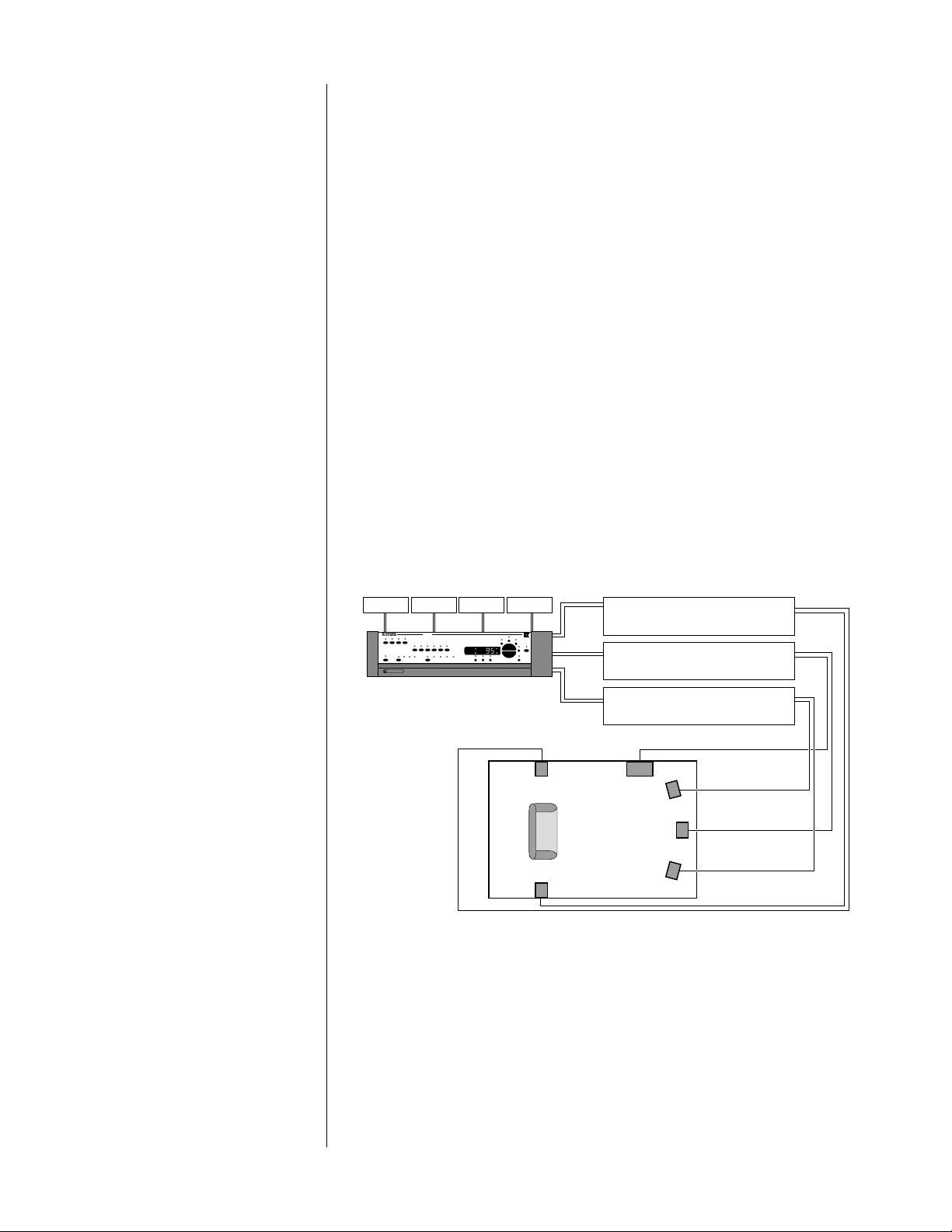
PAV s y ste m d i a g ram
vcr cd tunerlaserdisc
pav
vcr 1 vcr 2 laser disc tv/aux
cd 1 cd 2 tape 1 tape 2 bal/aux tuner
thx
pro
cinema
logic stereo mono off
main remote both record
standby input level delay recall
PROC EE D
surround modepath
LS
RS
LUCASFIL
M
®
balance
center
master
rear
mute
ref. level
sub
Ctr
Sub
RF
LF
Listening Room
Surround Power Amplifier
Center/Sub Power Amplifier
Main (Front) Power Amplifier
LS
RS
Ctr
Sub
RF
LF
Movie Sound and the PAV Unlike traditional stereo sources, Dolby Stereo™ movie soundtracks contain four
channels: Left, Center, Right and Surround. The three speakers in the front of the
room (L, C, and R) provide precise localization of sounds, or imaging, while the
surround channel is intended to be reproduced in a diffuse manner to the sides
and behind the audience—to literally “surround” that person in the ambient
sounds of the environment shown on the screen. Normally, a correctly operating
Surround channel would be so diffuse and enveloping as to be almost subliminal. Its purpose, after all, is to draw you into the movie, not to distract you from
it.
11
Page 12

Dolby Pro Logic™ Sources The PAV accurately decodes the Dolby Stereo™ soundtracks available in virtu-
ally all modern film soundtracks, many television shows, and even some music recordings. It does so by employing carefully optimized Dolby Pro Logic
circuitry, for superior performance and accuracy. Use the pro logic mode
whenever listening to most surround-encoded television shows, MTV (most of
which is now surround encoded), and other surround-encoded program material which has been created for general distribution.
THX Cinema Sources In addition, the PAV incorporates Home THX
®
audio processing to help movie
soundtracks make the transition from large movie theaters into the home. This
extra step is necessary because the acoustics of movie theaters and living rooms
are so different. Some adjustments are necessary in order to achieve the same
subjective effect in your home as in the finest movie auditoriums. These “adjustments” are precisely what Home THX offers. Use the THX cinema mode for
Dolby Stereo movies which were created for theatrical release—meaning virtually
all movies made since the late 1970’s.
Music and the PAV When it is time to enjoy some of your favorite music, the PAV gives you several
simple options, any of which may be selected by pressing the mode button to
cycle through the choices.
The stereo surround mode uses ambient cues contained in your normal stereo
recordings to create a realistic, full-bodied soundfield using all available speakers.
It has been carefully tuned to enhance stereo playback, and can be expected to
be relatively subtle rather than dramatic. (As with attending a live concert, one’s
attention should rarely be called to the characteristic sound of the “hall.” The
acoustics of the space in which the music is performed should enhance the musical experience without becoming an end unto themselves.)
The mono surround mode can be used to give acoustically “dry” mono record-
ings a sense of spaciousness. This mode can be used for historical monophonic
music recordings as well as for older movie classics which were recorded in
mono. This mode is particularly helpful when watching older, mono movies on a
big-screen television, where the disparity between aural and the visual size would
otherwise be a distraction to the movie experience.
12
Subwoofers and
Surround Modes
The surround off mode returns your system to two-channel stereo.
Finally, we have provided a “true mono” mode which reproduces both the Left
and the Right signals through the center channel speaker (and subwoofer) only.
The mono mode is sometimes desirable when listening to noisy monophonic
music recordings or movie soundtracks. Since noise tends to be random in nature, much of it cancels out when L+R are mixed together, as they are in this
mode.
If a subwoofer is connected to the sub outputs, it will normally be given the
deepest bass (below 80 Hz) at all times, independantly of the surround mode or
input selected. Whether or not the three front speakers are also given the deepest
bass information (below 80 Hz) to reproduce is determined by the settings of
the set speakers menu during setup. (See System Setup & Calibration for more
information).
Page 13
1 2 3 5 6 7 8
pav
vcr 1 vcr 2 laser disc tv/aux
cd 1 cd 2 tape 1 tape 2 bal/aux tuner
thx
pro
cinema
standby input level delay recall
main remote both record
PR O C E E D
logic stereo mono off
surround modepath
4
ref. level
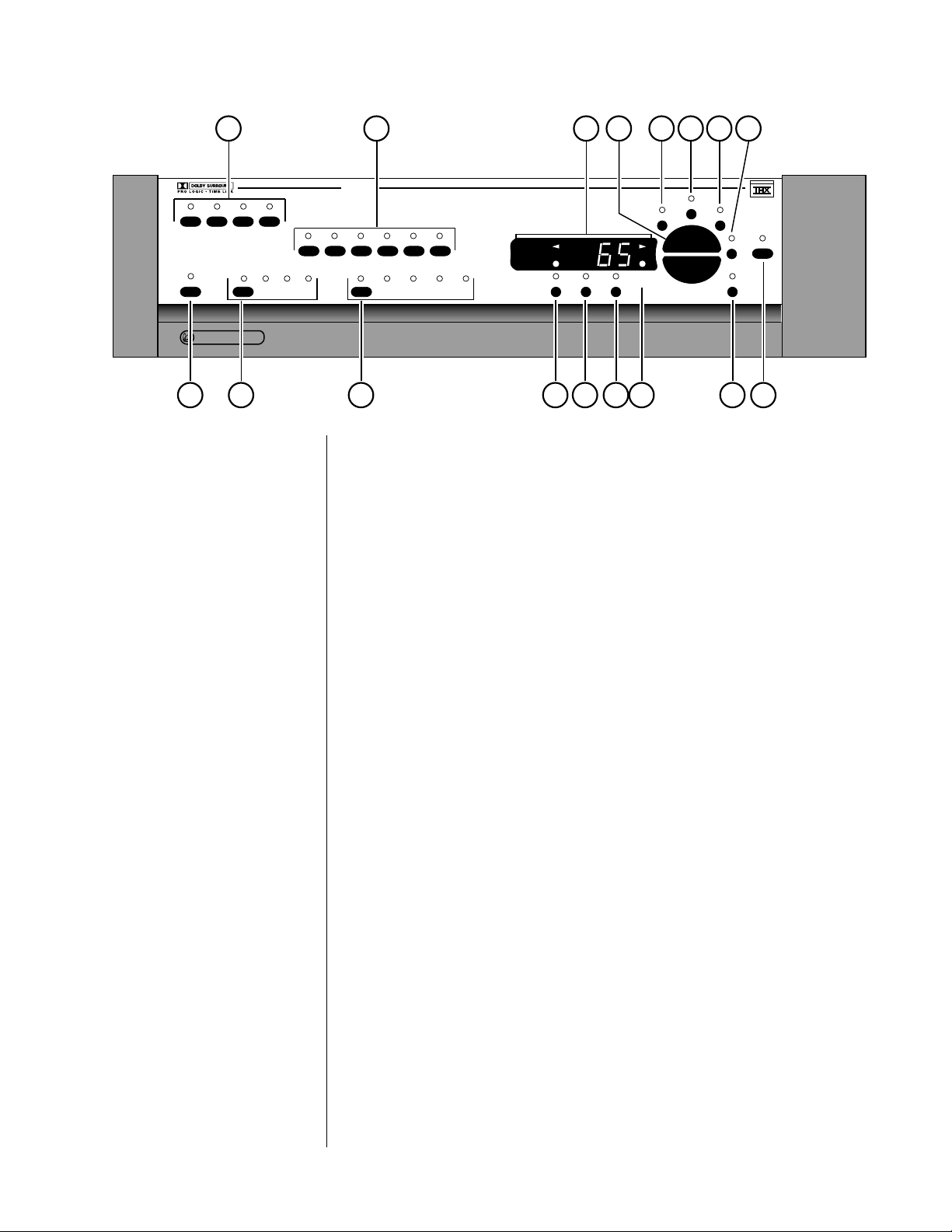
Front Panel
1 VIDEO SOURCE SELECTION BUTTONS
These four buttons select both the video and associated audio signals from
any of the four A/V inputs. To use these Selection Buttons, choose the appropriate path (see path, below). (For your music/home theater room,
“main” would be appropriate.) Then make your selection. The sophisticated
switching system employed in the PAV allows simultaneous, independent
routing of both audio and video signals along any or all of three paths:
main, remote and record.
master
balance
center
rear
LUCASFIL
M
®
mute
sub
91011121314151617
2 AUDIO SOURCE SELECTION BUTTONS
These six buttons select audio signals from among the six audio-only
inputs. (Note that both cd1 and bal/aux are balanced inputs which use
precision XLR connectors.) To use these selection buttons, choose the appropriate path (see path, below), and then make your selection.
Viewing Simulcasts Selecting any audio source after having selected a video source will cause
the newly-selected audio signal to “override” the audio portion of the video
selection (leaving the video signal unaffected). Thus, to enjoy a simulcast,
merely select the desired picture followed by the desired sound. To revert
to the sound of the video input, just press the video input button again.
3 MAIN DISPLAY
The main display provides information pertaining to the operation of the
PAV including relative volume levels, and is used in conjunction with the
buttons which surround it. At all volumes above a relatively quiet background level, and in all modes, the volume control enjoys a resolution of 0.5
dB. Thus a change of 10 decibels would be indicated by a change of 20 in
the display.
13
Page 14

The main display indicates the master volume by default, or the following offsets when chosen: balance, center, rear, subwoofer. In addition, it
can also display the input level (used in calibrating the Dolby Pro Logic
circuitry to the source material) and the rear channel delay (in milliseconds). Right- and Left-facing arrows are provided to indicate the direction of the balance offset. Finally, the infrared receiver and transmitter
for the remote control are positioned on the left side of the main display.
4 VOLUME +/–
These up/down buttons are used to make adjustments on the PAV, apart
from source and path selection. While the
volume +/– buttons normally
control the master volume of the music/home theater system (main path),
they can be used in concert with other buttons to control almost any aspect of system performance (as indicated below).
5MASTER
When the indicator above this button is lit, any adjustment made with the
volume +/– buttons will be applied to all loudspeakers equally, including
Center, Rears, and Subwoofer(s), thus raising or lowering the overall volume
without changing the relative balance of the various speakers. This is the
default mode of operation for the volume control, to which the PAV automatically returns after you make other adjustments.
6 BALANCE
Pressing this button followed by the volume +/– buttons will alter the rela-
tive volume of the Front Left and Front Right speakers. The direction of the
perceived image shift is indicated by the green arrowhead indicators in the
main display, as well as by the on screen display. Pressing volume + in the
balance mode will shift the image to the right (in a “positive” direction);
pressing volume – will shift the image to the left (in a “negative” direction).
7CENTER
Pressing this button followed by the volume +/– buttons will alter the vol-
ume of the Center speaker relative to all others. The resulting offset will be
indicated in the main display, as well as by the on screen display, until the
volume control reverts to its normal master mode. As an example, increasing the center channel volume by three steps would result in a 3 being displayed until the volume control reverted to normal operation, at which
point the display would again indicate the overall volume setting.
8 REAR
Pressing this button followed by the volume +/– buttons will alter the rela-
tive volume of the Rear speakers relative to all others. The resulting offset
will be indicated in the main display, as well as by the on screen display.
14
Page 15

9 MUTE
Pressing the mute button will reduce the main output level of the preamplifier by a user-modifiable amount, ranging from 2.5 to 55 decibels (5 to 110
in the main display). Pressing the mute button a second time without adjusting the volume will return it to its previous setting. If you adjust the volume with either the front panel buttons or the remote control while in the
mute mode, the preamplifier will adjust its volume from the muted volume
and disengage the mute function. The factory default setting of the mute
circuit is -20 dB (a change of 40 units in the Main Display). (See Using the
PAV for information on changing the factory default setting.)
10 SUB
Pressing this button followed by the
volume adjustment buttons will alter
the volume of the Subwoofer(s) relative to all other speakers. The resulting
offset will be indicated in the main display, as well as by the on screen dis-
play.
11 REFERENCE LEVEL INDICATOR
This LED indicator is lit when the PAV is playing at Home THX reference
level (normally calibrated during initial setup—see Output Level Calibra-
tion, p. 37).
12 RECALL BUTTON
Pressing the recall button restores the PAV to its calibrated reference settings for the relative output of all speakers. This is especially helpful after
having experimented with various settings of balance, center, rear, or sub,
or when comparing a modified surround default to “flat” balance, since one
touch of a button will restore your preamplifier to its original state (as determined by the setup calibrations stored in memory; see System Setup &
Calibration and Using the PAV for more details).
13 DELAY BUTTON
Pressing this button allows you to adjust (using the volume adjustment buttons) the delay introduced to the signal being sent to the rear channels,
between 15 and 30 milliseconds (mS). (See Setting the Surround Delay,
page 41, for more details.)
14 INPUT LEVEL BUTTON & INDICATOR
Pressing this button adjusts the input level (or offset) on the main signal
path. Together with the input level indicator in the main display immedi-
ately above it, it may be used to compensate for variations in level among
sources. This adjustment is important primarily for movie sources (since
Dolby Pro Logic circuitry is level-sensitive by its nature). When the Input
Level is set correctly, the green indicator LED should be on most or all of
the time during loud passages, but should never turn red (which would indicate an overload condition).
If overload should occur, pressing the input level button followed by the
volume – button will reduce the input level. Do so until the indicator re-
mains green during even the loudest passages.
15
Page 16

Conversely, if you rarely see the green LED illuminate during loud passages, you should increase the Input Level to compensate for the relatively low level of the source. Press the input level button, followed by
the volume + button to increase the input level.
15 SURROUND MODE SELECTOR
Pressing this button cycles among the various surround modes of the PAV:
•
THX cinema — for movies which were mixed for theatrical re-
lease; both THX cinema and pro logic indicators are lit, confirming that Pro Logic is in use whenever the THX cinema mode is
selected.
• pro logic — for all other surround-encoded material, such as
many TV shows and some music recordings; only the pro logic
indicator is lit.
• stereo surround — for enjoying two-channel stereo recordings
using all loudspeakers; the stereo surround indicator is lit.
• mono surround — for monophonic recordings which would benefit from some degree of additional ambience or spaciousness,
such as many classic movies and some sporting events; the mono
surround
indicator is lit.
• surround off — to return the system to two-channel stereo; the
surround off indicator is lit.
• mono —a “true” mono, reproduced only through the center channel speaker and subwoofer. Noisy mono soundtracks often enjoy
significant noise reduction by being reproduced in this mode;
both mono and off indicators are lit to denote the fact that the
surround circuitry is disengaged, leaving you with a “true” mono.
16 PATH SELECTOR
Pressing this button cycles among your various signal path options:
• main — the home theater; this path determines which video and
audio sources are sent to the Main outputs on the back of the
PAV. Sources selected for the main path are indicated in yellow on
the front panel LEDs. (If the LED blinks red, it is indicating a
tape loop condition caused by the same source having been se-
lected on the record path; deselect the source on the record path
first, then reselect your main source.)
• remote — determines which video and audio sources are sent to
the Remote outputs on the back of the PAV, to be sent to another
system elsewhere in the house. These sources are indicated in
green on the front panel LEDs. The remote path may also be
used as a secondary Record Output path if necessary.
• both — the audio and video signals for both main and remote
paths may be selected at the same time, for your convenience; as
when entertaining, perhaps, for whole-house background music.
Sources selected for “both” main and remote paths will be indicated by yellow LEDs (the same as for the main signal path).
• record — determines which video and audio sources are sent to
the various record output jacks. The source selected for the
record path is indicated on the front panel in red LEDs. As a
safety measure, the PAV will prevent the selection of any recordable device as its own source (to avoid feedback loops). If such a
selection is attempted, the PAV will cause the appropriate LED to
16
Page 17

flash yellow on the front panel, indicating a conflict on the
main path. The PAV will also display the words tape loop on
screen as a warning.
Tip: To avoid any possibility of running into a “Tape Loop”
problem (where the PAV prevents you from choosing what
you want, in order to protect the system from possible
damage), simply select a non-recording source such as TV
on the record path.
17 STANDBY BUTTON
Pressing this button places the PAV in standby mode, turning off the display,
disengaging all control functions, and turning off all outputs. The internal
circuitry remains on in order to maximize performance on demand by virtue of all circuits remaining thermally stable. Lest you think this wasteful,
you should know that the PAV draws less than power than a typical light
bulb, whether in standby or fully on. The benefits of having it always
warmed up and ready to go (and always able to respond to remote control
commands) far outweigh the small amount of power used. We recommend
using the rear panel power switch only when you will be away from the
house for extended period of time, such as during a vacation.
There is another good reason for using the PAV’s standby mode. The PAV
will generate a full-frame black video signal at its video outputs during
standby, rather than passing no signal at all. This is particularly helpful with
many projections televisions, since it gives the projector a “sync” signal to
lock onto without calling for any light to be generated. This feature allows
the projector to remain fully warmed up at all times without risking damage to the phosphors which create the projected light.
17
Page 18
1 2 3 4
vcr1 vcr2 tape1 tape2
vcr1 vcr2 tape1 tape2
R
PR O C E E D
p a v
13
laser
disctvaux cd2 tuner
center
rear
sub
surround remote main
by MADRIGAL AUDIO LABORATORIES
11
10
9 7 6 58
12
cd1 bal/aux
PUSH
21
3
12312
PUSH
21
3
main remote
i n p u t s
3
o u t p u t s
PUSH
21
3
12312
PUSH
21
3
3
laser
disc
main rem
aux
tv
vcr1 vcr2
vcr1 vcr2
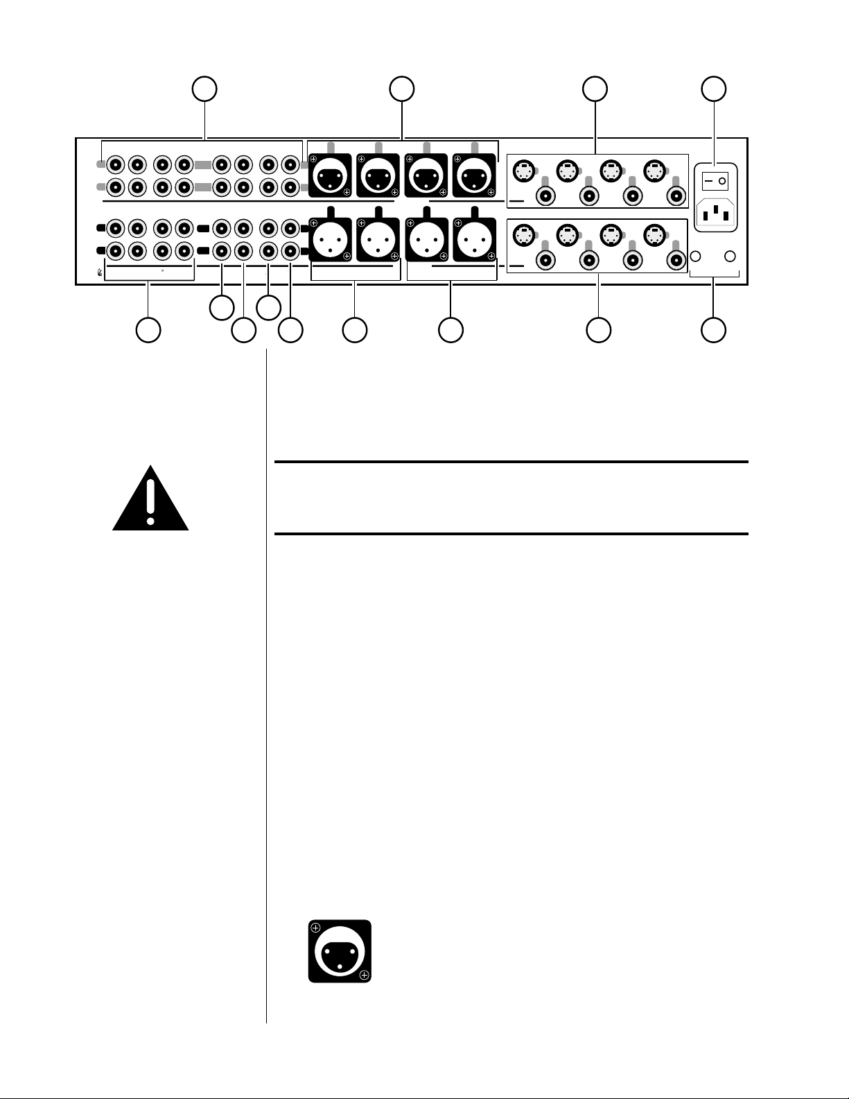
Rear Panel
Caution! Disconnect all associated equipment from the AC mains
BEFORE making any signal connections and applying power
to the PAV.
remote
i. r. turn-on
1 SINGLE-ENDED AUDIO INPUTS (8)
Accepts right-channel and left-channel audio signals from source equipment
with single-ended (RCA) outputs. Single-ended audio inputs are provided
for a total of eight components, designated: vcr1, vcr2, tape1, tape2, a
laserdisc player, your tv (or auxiliary component), a cd2, and a tuner. Note
that the video portion of the signal from any video source (VCR, laserdisc,
TV) would be connected on the right side of the rear panel in the Video
Input section. (See below.)
Connect the right-channel and left-channel single-ended outputs of your
various source components to the corresponding inputs on the PAV.
2 BALANCED AUDIO INPUTS (2)
Accepts right-channel and left-channel signals from source equipment with
balanced outputs. Provisions are made for two balanced signals via high
quality XLR connectors, designated cd1 and bal/aux.
The pin assignments of these XLR-type female input connectors are:
PUSH
21
3
Pin 1: Signal ground
Pin 2: Signal + (non-inverting)
Pin 3: Signal – (inverting)
Connector ground lug: chassis ground
18
Page 19
These pin assignments are consistent with the standards adopted by the
Audio Engineering Society. Refer to the operating manuals of your balanced-output line-level sources to verify that the pin assignments of their
output connectors correspond to the PAV. If not, wire the cables so that the
appropriate output pin connects to the equivalent input pin.
Connect the right-channel and left-channel balanced outputs of your source
components to the corresponding balanced inputs on the PAV.
Note: If you do not have balanced sources and need more single-
ended inputs, it is possible to fabricate a cable to connect linelevel sources with single-ended output to these balanced inputs:
1
ground
signal +
22-gauge
2
3
buss wire
Male RCA
(connect to source)
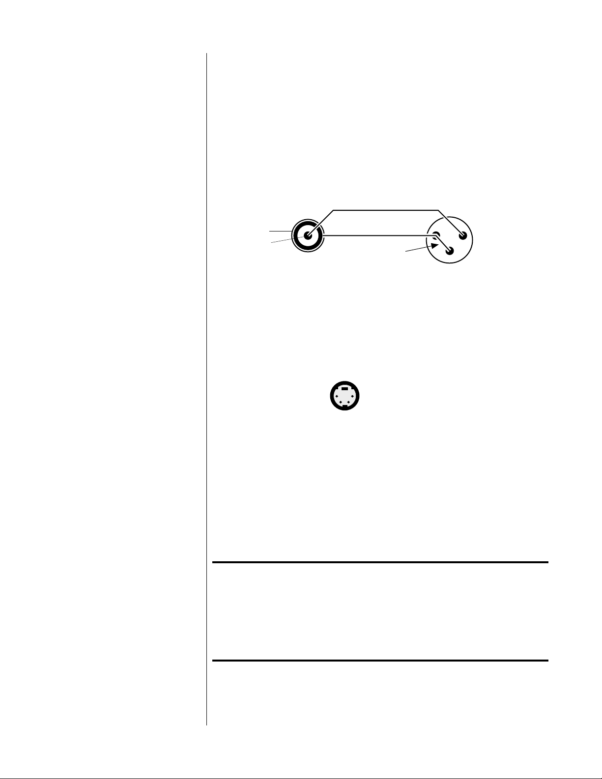
3 VIDEO INPUTS (4)
Four video inputs are provided in the PAV, designated: laserdisc, tv/aux,
vcr1, and vcr2. These inputs may be configured for use with either com-
posite or S-video (Y/C) signals during setup. Composite video inputs use
RCA connectors. S-video inputs utilize “S” connectors:
Male XLR
(connect to PAV)
S-video connector
The PAV does not provide for “cross-feeding” of S-video and composite signals. Any signal entering the PAV in either format will be output in the same
format only. We strongly recommend standardizing on one or the other
throughout the system for maximum ease of use. In addition, using both
the composite and the S-video inputs simultaneously may result in a loss of
video signal quality.
Connect the video outputs of your video components to the corresponding
video inputs on the PAV. (See System Setup and Calibration for more infor-
mation on programming these inputs for either composite or S-video use.)
Installation Note: S-video (Y/C) signals are more susceptible to degradation
over long wire runs. The quality of wire used makes a
significant difference, but regardless, it is generally
inadvisable to run S-video cables more than six or eight feet
(2–2.5 meters). Composite video signals hold up better over
longer runs, especially when high quality 75Ω cable such as
Madrigal MDC-2 is used.
19
Page 20

4 AC POWER SWITCH AND AC POWER INPUT
An AC power switch is provided which disconnects the PAV from the wall
outlet’s AC power. The PAV is designed to be left in Standby when not in
use, rather than completely “off.” Being in Standby allows it to respond to
commands from the remote control and maintains a stable operating temperature at all times for optimal performance and longevity.
Plug the supplied three-prong power cord into the AC Power Input
recepticle provided before plugging the power cord into the wall. If a
longer AC power cord is required for your application, be sure to use a
three-conductor power cord which conforms to IEC standards.
The Proceed PAV has been safety-tested and is designed
for operation with a three-conductor power cord. Do not
defeat the “third pin” or earth ground of the AC power cord.
Beside the power switch you will find a communications port. This is reserved for future use (communicating with the PAV's companion piece, the
Digital Surround Decoder). Do not insert anything into this port other than
the communications cable from a “DSD.”
5 REMOTE IR AND REMOTE TURN-ON
A 1⁄8" “mini” jack labeled remote ir. in the lower right corner of the rear
panel provides direct access to the infrared control circuitry of the PAV. It
may be configured during setup (in an on screen menu) to interpret incoming signals in either of two ways:
• Remote: when in Remote mode, the PAV will interpret any com-
mand entering through the remote IR jack as being intended to
affect the remote path only. This feature allows easy access to all
sources connected to the PAV from elsewhere in the house with
the addition of any commercially-available IR repeater.
• Local: when in the Local mode the remote IR jack replaces the
infrared receiver in the main display of the front panel. This
mode is most often used with an IR repeater when the PAV and
other components are placed inside of cabinets (preventing the
normal IR receiver from receiving remote commands). Setting the
remote IR jack to local will disable the IR receiver in the main
display to avoid inconsistent operation which might be caused by
interference between the two. (See Programming the IR Input,
page 48.)
The incoming signal for the remote IR input should conform to widelyaccepted IR repeater standards: that is, the signal present should be between 3-15 volts DC at less than 100 mA current, with a positive tip polarity, as shown below:
20
IR input tip polarity
+–
3-15 volts @ less
than 100 mA
Page 21

Your Proceed dealer can help you take advantage of these design features to maximize your system’s versatility.
The remote turn-on output to the right of the remote ir input (as seen
from the rear) can be used to toggle Proceed power amplifiers between
standby and operate in concert with the operational status of the PAV.
This output normally provides a 300 msec long, 8 volt positive pulse
whenever the PAV turns on, and a 600 msec long, 8 volt positive pulse
whenever the PAV turns off. (Alternatively, the PAV may be configured to
provide a level control voltage that can be used by certain Niles controllers and similar products. See System Setup and Calibration for more in-
formation.)
To enable the PAV to control the turn-on and turn-off of the associated
Proceed amplifiers, connect a wire terminated with a
1
⁄8" “mini” plug at
both ends (available in various lengths at electronics supply stores such
as Radio Shack, or may be custom made to length by your installing
dealer) between the remote turn-on output of the PAV and the remote
turn-on input of the AMP. If more than one Proceed amplifier is being
used, simple “Y-adapters” may be used to daisy-chain the turn-on signal
for up to three AMPs’ turn-on inputs.
6 VIDEO OUTPUTS
Four video outputs are provided in the PAV: main, remote, vcr1, and vcr2.
S-video (Y/C) outputs utilize four-conductor “S” connectors, while the composite video outputs use RCA connectors.
The main output should be connected to your video monitor in the main
home theater system. The remote output can be used to feed video signals
to another system elsewhere in the house. The remaining vcr1 and vcr2
outputs are used for making recordings on those decks via the PAV, much
as you would make audio cassette recordings with a traditional preamplifier
or receiver. Connect them to the corresponding inputs on the back of those
video tape recorders.
Installation Note: S-video (Y/C) signals are more susceptible to degradation
over long wire runs. The quality of wire used makes a
significant difference, but regardless, it is generally
inadvisable to run S-video cables more than six or eight feet
(2–2.5 meters). Composite video signals hold up better over
longer runs, especially when high quality 75Ω cable such as
Madrigal MDC-2 is used.
The PAV does not provide for “cross-feeding” of S-video and composite signals. Any signal entering the PAV in either format will be output in the same
format only. For most people, it is simplest to standardize on one format or
the other throughout the system. While it is possible to use a combination
of both types of signal, this setup would require manual switching of inputs on the video monitor whenever the monitored video source changed.
In addition, using both the composite and the S-video outputs simultaneously may result in a loss of video signal quality.
21
Page 22
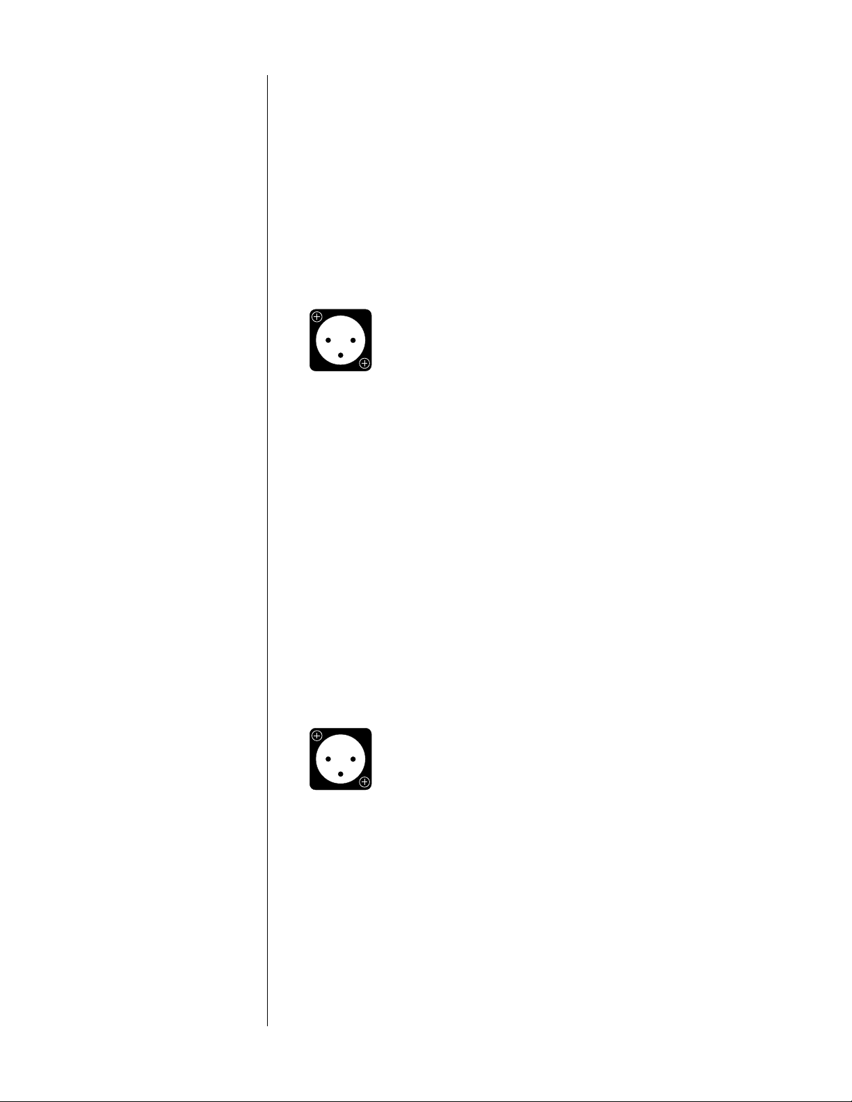
7 REMOTE BALANCED OUTPUTS
If the system being used in the remote zone is equipped with balanced
(sometimes called “differential”) inputs, it is best to use these balanced outputs on your PAV. A balanced signal from preamplifier to power amplifier
will offer the highest possible performance with the best immunity from
common-mode noise, such as electromagnetic interference (EMI) or radio
frequency interference (RFI). This characteristic immunity is particularly important when using long cable runs, as may be expected when sending a
signal to a remote location. The balanced output signal is made available by
way of precision male XLR connectors (requiring female XLRs on the PAV
end of the interconnecting cable).
The pin assignments of these XLR-type male outputs are:
Pin 1: Signal ground
12
3
Pin 2: Signal + (non-inverting)
Pin 3: Signal – (inverting)
Connector ground lug: chassis ground
Refer to your amplifier’s operating manual to verify that the pin assignments
of its input connectors correspond to the PAV. If not, wire the cable so that
the appropriate output pin connects to the equivalent input pin.
Connect the right-channel and left-channel balanced remote outputs of
the PAV to the appropriate balanced inputs of the remote system.
8 MAIN BALANCED OUTPUT
If the power amplifier being used to drive the Front Left and Front Right
speakers is equipped with balanced (sometimes called “differential”) inputs,
it is best to use the balanced main outputs on your PAV. A balanced signal
from preamplifier to power amplifier will offer the highest possible performance with the best immunity from common-mode noise, such as radio
frequency interference (RFI). The balanced output signal is made available
by way of precision male XLR connectors (requiring female XLRs on the
preamplifier end of the interconnecting cable).
The pin assignments of these XLR-type male outputs are:
Pin 1: Signal ground
12
3
Pin 2: Signal + (non-inverting)
Pin 3: Signal – (inverting)
Connector ground lug: chassis ground
Refer to your power amplifier’s operating manual to verify that the pin assignments of its input connectors correspond to the PAV. If not, wire the
cable so that the appropriate output pin connects to the equivalent input
pin.
Connect the right-channel and left-channel balanced main outputs of the
PAV to the appropriate balanced inputs of the remote system.
22
9 SINGLE-ENDED MAIN OUTPUTS
Single-ended (“unbalanced”) outputs are provided for compatibility with a
wide range of associated components.
Page 23

If you use the single-ended main outputs, connect them to the corresponding inputs of the amplifier being used to drive the Front Left and
Front Right speakers.
10 SINGLE-ENDED REMOTE OUTPUTS
Single-ended (“unbalanced”) outputs are provided for compatibility with a
wide range of associated components, including power amplifiers and electronic crossovers.
If you use the single-ended remote outputs, connect them to the corresponding inputs of your remote amplifier (or other device).
11 REAR SURROUND OUTPUTS (SINGLE-ENDED)
Connect these outputs to the input of the power amplifier being used to
drive the surround speakers, which are normally located at the sides or the
rear of the room.
12 CENTER & SUBWOOFER OUTPUTS (SINGLE-ENDED)
The upper of these two RCA jacks should be connected to the amplifier
channel which will drive your center channel speaker; the lower RCA jack
should be connected to the amplifier channel which will drive your
subwoofer(s).
If you have two channels of amplification driving multiple subwoofers, simply wire them in parallel from this output, using a Y-adapter. The output
circuitry of the PAV can easily handle the extra amplifier without any loss of
performance.
Please Note: If your system does not have a subwoofer, leave the sub
output empty. Also be sure the crossover is turned off during
Setup in order to give your front loudspeakers a full-range
signal. (See
13 RECORD OUTPUTS (SINGLE-ENDED)
Four audio record outputs are provided, which are designed to work in
concert with their corresponding inputs. For example, you would connect
the vcr1 outputs to the audio input jacks on the video tape recorder you
had connected to the vcr1 input. The record outputs are: vcr1, vcr2, tape1,
tape2.
System Setup & Calibration
for more details.)
23
Page 24
Learning Remote Control
installing batteries in
the remote control
pav
audio
cd dvd aux
power
standby
input
record
mute
prev
rev fwd
stop
vcr1 vcr2 laserdisc THX
123
tv/vcr1 cd1 cd2 mode
46
5
tape1 tape2 bal/aux status
78
tuner
menu
0
on
display input delay recall
screen
adjust channel
volume
play
volume
9
enter
next
pause
late night
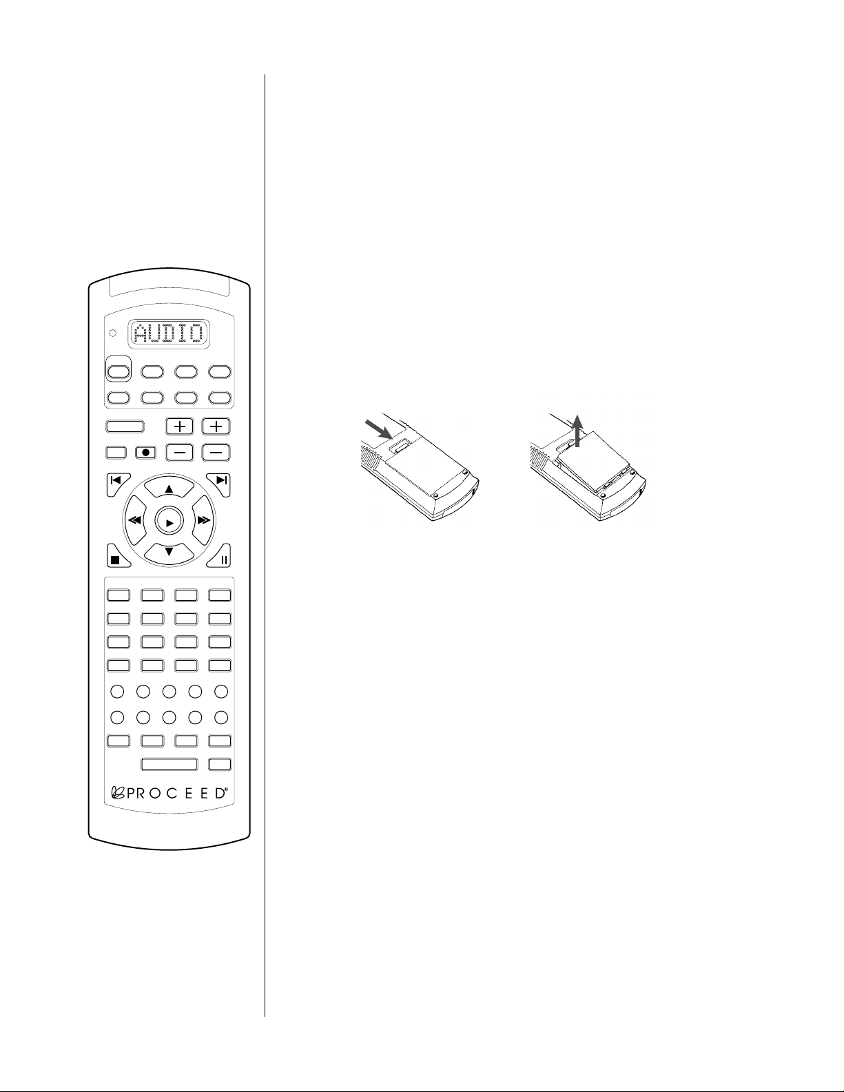
This remote control uses four AAA 1.5V batteries. Please be sure to match
the batteries with the (+) and (–) markings inside the battery compartment
during installation.
A: To Open and Close the Battery Compartment Cover
To open the battery cover, push the latch forward toward the top of the
remote control, and lift the latch up.
To close the battery cover, slide the battery cover straight back in (toward
the top of the remote) and push down until it “clicks” into place.
cblvcrtvsat
B: Low Battery Message
When the Liquid Crystal Display (LCD) flashes L_BAT, the batteries
should be replaced.
Note: Batteries should last about 6 months under normal conditions.
This remote control will retain its programmed memory for up to one
year after the batteries are removed and up to ten years after the batteries
go “dead”.
24
m1 m2
subrearcenterbalancemaster
IMPORTANT NOTE:
m3
m4
path
light
The PAV’s remote may be programmed to control up to eight devices, including the PAV. Before using the remote, it is important to remember to
press the Device Control Selector button that corresponds to the unit you
wish to operate. Before using the remote with other products, follow the
instructions in Programming and Using the Remote Control.
It is also important to remember that many of the buttons on the remote
take on different functions, depending on the product selected using the
Device Control Selectors. The descriptions shown here primarily detail
the functions of the remote when it is used to operate the PAV.
Page 25

1 LCD DISPLAY
This Liquid Crystal Display (LCD) shows messages as to which Device
Mode the remote is currently in, as well as various messages displayed
pav
audio
power
standby
input
mute
prev
cd dvd aux
adjust channel
record
volume
cblvcrtvsat
next
while programming your remote.
2 PROGRAMMING STATUS LED
This three-color (green/red/orange) LED indicates the remote’s status
when IR commands are being transferred from another compatible IR
remote. For more information on “teaching” the remote to learn IR
commands see Programming and Using the Remote Control.
rev fwd
play
volume
stop
vcr1 vcr2 laserdisc THX
123
tv/vcr1 cd1 cd2 mode
46
5
tape1 tape2 bal/aux status
78
on
screen
m1 m2
9
tuner
0
display input delay recall
late night
entermenu
m3
light
pause
3 DEVICE CONTROL SELECTORS
Press the
pav/audio button to use the remote control for operation of
the PAV Audio/Video Preamplifier. Note that the Programming Status LED
will briefly blink red and the LCD Display will confirm your selection by
switching to AUDIO.
Press any of the other seven Device Control Selectors to use the remote
subrearcenterbalancemaster
m4
path
to control the functions of another audio/video device.
4TRANSPORT BUTTONS
This section of the PAV learning remote control groups the most-used
features of a source component together, be it a CD player, a VCR, or
a laserdisc player. This design allows you to put one or more of the
remote controls in your coffee-table collection away in a drawer, leaving
only the single PAV remote to provide all of the day-to-day commands
you require.
NOTE:
•the volume +/–: buttons normally adjust the overall system
volume, although they are also used in conjunction with other
buttons and/or menu items to vary most of the available system adjustments. When navigating within the on screen menu
system, the volume +/– buttons will either:
• move the cursor up or down
[when the “select-it” cursor (→) is displayed]
• increment/decrement the value of a selected menu item
[when the “change-it” cursor (x) is displayed]
For more information on the teaching your remote new functions, see
Programming and Using the Remote Control.
5 INPUT SELECTION AND NUMERIC KEYPAD
This section of buttons normally provides direct access to the inputs
printed above the various buttons. However, you may also “teach” the
learning remote to operate as a conventional numeric keypad such
as you might have on the remote controls of your cable decoder or
television.
25
Page 26

6 MENU, ENTER BUTTONS
• menu: when the on-screen menu is not displayed, pressing this
button will bring up the main menu. Once in the menu system,
pressing menu will exit your current level without making any
permanent changes, returning you to the next-higher level. Repeated pushes of menu will ultimately take you out of the menu
system entirely (e.g., will exit the topmost level of the menu system,
taking you out of the menus entirely.)
•
enter: when navigating through the on-screen menus, the enter
button serves two purposes: indicating that something is to be
changed, and then confirming the change. When the “select-it”
cursor
(→) is pointing to an item that has a sub-menu, pressing
enter will take you to that sub-menu. Otherwise, pressing enter
will change the “select-it” cursor (→) to the “change-it” cursor
(x) so the menu item may be changed directly. (At this point,
using the volume +/– buttons will change the value of the item
in question.) Either way, pressing enter after changing a value
confirms the change.
7 PAV OPERATIONAL CONTROLS
This section of the learning remote contains most of the controls for
the Proceed PAV.
• on screen: pressing this button will turn the on screen display
off to avoid the distraction of messages whenever you adjust
the volume, change surround modes, etc. Pressing the on
screen
button again will restore the normal on screen function.
• display: pressing this button will turn off the front panel display of the PAV to facilitate listening to music or watching
movies in a darkened room without visual distractions. The
PAV’s display will turn back on momentarily when adjusting
the unit’s operation in order to acknowledge the changes. The
display may be returned to its normal, always-on mode by
pressing the display button again.
• input: pressing this button temporarily places the volume +/–
keys in input level mode, allowing you to fine-tune the input
sensitivity of each particular input for proper Pro Logic
calibration. This control also allows you to adjust the relative
volumes of the various source components to avoid abrupt
changes in volume when switching between inputs. (Note that
a default setting for this function may be set for each input;
see Setting Input Defaults. Note also that this control is never
needed with digital sources—only for analog ones.)
• delay: pressing this button, followed by pressing center, rear, or
sub temporarily allows the volume +/– keys to adjust the amount
of time the selected channel(s) signal is delayed relative to the
front channels. This time delay may be adjusted between 0-15 mS
in 1 mS increments (in the case of Pro Logic, this delay is added
to the 15 mS delay for the rear speakers required by Pro Logic).
26
Page 27

• recall: pressing this button restores the various channel
offsets to their calibrated, most accurate settings (set up during
installation and calibration). You can experiment with adjusting
the levels of the subwoofers, center channel, surrounds, etc. to
suit your preference or a particular recording, knowing that a
single press of recall will restore the PAV/PDSD to its calibrated
settings.
•
master: pressing this button allows the volume +/– keys to affec t
the overall volume of the system, maintaining any relative settings
between the various loudspeakers. This is the default mode for
the volume +/– keys, to which the PAV will return after a few
seconds of inactivity.
• balance: pressing this button temporarily allows the volume +/–
keys to affect the balance of the left front and right front speakers
rather than the overall volume.
• center: pressing this button temporarily allows the volume +/–
keys to affect the level of the center front speaker relative to
the rest of the system.
• rear: pressing this button temporarily allows the volume +/–
keys to affect the level of the rear (surround) speakers relative
to the rest of the system.
• sub: pressing this button temporarily allows the volume +/–
keys to affect the level of the subwoofer relative to the rest of
the system.
• mute: pressing this button duplicates the function of the mute
button on the front panel, reducing the volume of the main
system by a user-selectable amount.
• path: pressing this button will cycle the PAV through the various signal paths. Having selected a particular path, subsequent
source selections affect only that path (e.g. , main, remote,
both, or record).
8MEMORY BUTTONS
There are five memory buttons (m1~m4, power) that are designed to
store up to 15 commands in each button. Pressing any one of the
memory buttons will send out the series of commands that are stored
in the button. These buttons can be programmed to store Favorite Channels, Macro Commands, or to “relocate” functions from one mode to
another. For more information on these buttons see Programming and
Using the Remote Control.
9 LIGHT BUTTON
All buttons and the LCD on the PAV/PDSD remote are back-lit for seven
seconds when the light button is pressed. The backlight is extended an
additional seven seconds with any button press while the backlight is on.
27
Page 28

10 THX®, mode, status, late night, standby BUTTONS
Several commonly used button are placed along the top right side of
the PAV/PDSD remote control where they may be easily found even
in dimly-lit rooms. Note that these buttons are round, rather than the
rectangular shape used in most of the rest of the remote control. This
further helps to identify them by touch.
•
THX: pressing this button will toggle the THX processing within
the PAV/PDSD on and off. When listening to a Dolby Pro Logic
signal, the four channel version of THX processing is used; the
5.1 channel version of THX is used for discrete multichannel
digital sources such as Dolby Digital, DTS, or MPEG/Musicam.
• mode: pressing this button cycles the PAV through the various
two-channel surround processing modes (pro logic, stereo sur-
round
, mono surround, two-channel stereo, and mono), indi-
cated both on the front panel and on screen. (PAV ow n e r s w ill
note that Home THX Cinema mode is no longer part of this list,
since it has its own button now, and may be added to discrete
multichannel sources as well as to the two-channel surround
modes listed here.)
• status: pressing and holding the status button will display a
variety of information pertaining to the current operational status
of the PAV/PDSD (for as long as you continue to hold the button). For example, if you ever find yourself wondering what
surround mode you are in, pressing status will let you know.
• late night: modern Dolby Digital soundtracks can sometimes
have more dynamic range than is desired, particularly if you
are listening at night or in an apartment building and wish not
to disturb others. Pressing the late night button will cycle you
through three levels of dynamic range control: none, low, and
high. High control will result in the greatest compression with
the least opportunity for loud “surprises” in the soundtrack’s
level.
• standby: this button will place the PAV/PDSD into standby
mode. Pressing it again will return the PAV/PDSD to operate
mode.
28
For more information on teaching your remote new functions, see
Programming and Using the Remote Control.
Page 29

Planning Your Installation
The information contained within this section is intended to help get someone
started who wishes to design and install their own sophisticated A/V system built
around the Proceed PAV. However, it cannot be considered a substitute for the experience, expertise and specialized training of an audio/video installation professional. (See A Word About Installation, page 10.)
Choosing The Equipment The list of equipment needed for a full home theater system based on the PAV
is fairly straightforward:
• The Proceed PAV
• At least six channels of amplification (Left, Center, Right, two Surrounds, and one or more Subwoofers)
• Additional amplification (with volume control) and loudspeakers if
a remote zone is to be used. (Alternatively, this output may be
used in conjunction with a third-party multi-room system.)
• Left, Center and Right (LCR) front speakers with appropriate stands
or mounting brackets
• One or more subwoofers (required with THX speaker systems;
otherwise optional, but recommended)
• A pair of Surround speakers with appropriate stands or mounting
brackets
• Assorted appropriate interconnecting cables, speaker wires, etc.
Planning Your
Equipment Placement
Of course, you will also need at least one source and a display system. The best
consumer video sources, in order of quality, are:
• Laserdisc
• Direct Broadcast Satellite link (DBS, DSS)
• a good cable-TV or antenna signal
•Super-VHS tape
• Hi-8 mm videotape
• regular VHS videotape
The “light pollution” created by some components can be significant and distracting. Ideally, all equipment should be conveniently located for operation, but any
lights and other indicators should be out of your direct field of vision when
viewing the television picture. The various indicator lights, though essential for
proper operation, can be distracting when listening to music or watching a movie.
While the PAV’s display may be turned off (with the display button on the remote control) to eliminate this problem, other components are unlikely to have
this feature.
Care should also be taken that any mechanical noise created by VCRs, laserdisc
players, etc. does not intrude on the viewing experience. Placing the equipment
behind opaque doors, inside a cabinet addresses both light and noise concerns.
Should this option be chosen, a hard-wired remote IR input is provided on the
PAV’s rear panel to replace the IR input which would normally be received
through the receiver in main display. Alternatively, locating the components well
away from the field of vision can be effective (if mechanical noise from transports, etc. is not a problem).
29
Page 30

Attention should be paid to the accessibility of the infrared control signal to
the components. Most people instinctively aim remote controls at the screen,
without thinking about the location of the equipment. It is a good idea to locate a small infrared “repeater” in the vicinity of the screen, set up to relay the
signal into the equipment area and/or the PAV’s remote IR input. This is espe-
cially true if the equipment has been isolated from plain view, inside cabinetry.
The “Correct” Size for
Your Television Screen
Video images will often be displayed on some sort of projection system, since
the increased size will give you a more film-like experience. There may be situations where a 31"–35" direct-view television is appropriate (in smaller rooms, for
example). But do not give in to this temptation too easily—part of the theater
experience is the visual impact of having your field of vision dominated by the
size of the image on the screen. A good rule of thumb is to use a
diagonal screen size of approximately 1⁄2 to 1⁄4 the planned viewing distance. Thus,
if your seating is 12 feet from the screen, you would like to use a television with
a 3 to 6 foot (36"-72") diagonal screen measurement. In this case, a 35" directview television might be just adequate. A larger screen would be preferable, especially if you plan to watch many letterboxed movies. If your video system includes a line doubler for enhanced resolution, take advantage of the improved
picture clarity by using a larger screen (closer to the one-half-the-distance figure).
The Power Amplifiers Given the dynamic range of modern soundtracks and people’s expectations of
their home theater systems, at least 100 w/ch is recommended for all six channels, with few exceptions. Still more power may be required in unusually large
rooms.
A common misconception is that the center and surround speakers have lower
power requirements than do the rest. This is proven untrue by the mathematics
of Dolby Pro Logic processing. The center channel is the hardest-working speaker
in a movie soundtrack’s mix. You should also be forewarned that the surrounds
are working harder than your first impression might indicate. While they may require less power on average, there are moments during which they are the loudest speakers in the room (as when an aircraft seems to fly overhead, for example). Prudent system design requires that the surround channels have enough
power to reproduce their signals without amplifier clipping, even under such a
worst-case scenario.
The Left, Center and Right
(LCR) Front Speakers
30
The goal of the front speakers is to accurately recreate the sounds that would be
coming directly at you in real life situations. It is important that they be accurate
in terms of tonal balance, dynamic capabilities, and imaging precision if they are
to recreate a convincing soundstage (whether of music or film soundtracks). They
also need to be well-matched to one another—do not skimp on the center channel speaker, as it is the most important loudspeaker in the entire system when it
comes to movie reproduction.
Ideally, all three Front speakers would be at the height of the screen. Of course,
the center channel speaker would then obscure the screen, so placement above
or below the screen is usually required. All three speakers should be close to the
same height, however, to avoid distracting changes in apparent altitude as sound
is panned across the screen.
Page 31

toe-in of left & right speakers
L sur
R sur
sub
L
C
R
Some toe-in of the Left and Right speakers toward the main listening area (see
above) will help minimize side wall reflections and balance the sound for people
at the extreme edges of the viewing area. Placing the center speaker at the same
distance as the left and right is also important (note the arc in the diagram
above).
If possible, it is usually desirable to have the side walls between the front speakers and the listener be acoustically absorptive to further minimize early side wall
reflections. Plush drapes, wall hangings, and various commercially-available materials can do the trick nicely. (Consult with your dealer for further ideas.)
The Subwoofer(s) The Proceed PAV is designed to use a common-bass subwoofer, meaning that the
low frequency information from the controller is summed to a single channel.
This can be done without degrading the stereo effect because the human ear
cannot readily localize sounds below about 120 Hz. In addition, virtually all program material (music and movies) is monophonic below 100 Hz. As a result,
there is a great deal of flexibility in the placement of the subwoofer(s). The primary goal is to have bass which can deliver visceral impact without becoming
boomy or distorted. In order to achieve this, attention must be paid to room
placement to minimize the “room modes” (or standing waves).
A good rule of thumb is to place your subwoofer(s) asymmetrically in the room,
at “odd fractions” (1⁄3, 1⁄5, 2⁄5, etc.) of the room’s length or width.
L sur
R sur
sub
1
⁄3
L
C
R
You may also want to try to keep your subwoofer(s) within three feet (one
meter) of the circle formed by anchoring a string at the main listening position
and swinging the other end through the front speakers. (Doing so minimizes and
31
Page 32

phase-induced irregularities at the crossover frequency of 80 Hz.) Of these
two guidelines, the first is usually more significant sonically, as it tends to
minimize the audibility of the room’s modes. Avoid corner placement, as this
typically increases bass quantity at the expense of bass quality (by stimulating
every room mode supported by the room).
The actual number of subwoofers used in an installation will depend on both
the size of the room and on the manufacturer’s design. Of course, having multiple
subwoofers enhances the maximum level at which they will play. Additionally,
there is an advantage to having more than one subwoofer in the room. Smoother
bass may be obtained by placing two subwoofers asymmetrically in the room,
since different sets of room modes would then be excited by each. The peaks of
one set of room modes could offset the valleys of the other one to some degree.
The Surround Speakers Ideally, the rear speakers will create a diffuse, non-localizable soundfield which
envelopes the listener. Creating this effect depends in part on the loudspeakers
chosen for the job.
If THX-certified dipolar surround speakers are used, they should be located high
and to the sides of the listening area, firing to the front and the rear of the room.
(See diagram, below.) This placement ensures that the audience will not be able
to localize them as sources of sound, but rather will be enveloped in a diffuse
soundfield. They should be at least two feet above ear level when seated. Ideally,
they would be placed somewhat above ear level even when standing, so that they
are unlikely to be localized as people walk around the room.
dipolar surround placement
L sur
R sur
sub
L
C
R
If more traditional speakers are used, they should be placed such that their output is scattered across the rear of the room. (See diagram, next page.) Often, the
best results will be obtained by placing them relatively high and slightly behind
the listener, cross-firing across the rear wall so as to create a large number of reflections with relatively little direct sound arriving at the listening position.
32
Page 33

conventional surround
g
placement
L sur
sub
L
C
The Wiring Low impedance speaker wire must be used throughout the system. This ensures
example wire lengths chart
R sur
R
the most efficient transmission of power from the amplifiers to the speakers,
which minimizes several forms of audible distortion. Surprisingly, not all speaker
wires (including some of the audiophile variety) meet the necessary criteria. As
always, your best source of advice is your trained dealer/installer. However, the
table below may be used as a worst-case general guide. When in doubt, use a
thicker (heavier gauge) wire than is specified below.
Example Wire Lengths
Length
(in Feet)
up to 12'
up to 18'
up to 29'
up to 51'
AWG Size
& Strandin
16 gauge
(19/29)
14 gauge
(19/27)
12 gauge
(65/30)
10 gauge
(105/30)
Working in Unusually
Large Rooms
Large rooms (in the 4000-6000 cubic feet range) have so much air to move that
they may benefit from having additional subwoofers for greater bass impact. The
PAV’s subwoofer output can easily drive several power amplifiers—simply split its
output with Y-connectors.
Another technique for large rooms involves the construction of risers for the seating area in a dedicated home theater. Risers tend to enhance the visceral effect of
deep bass by providing a resonant platform for the couches and chairs, thereby
transmitting structural as well as airborne vibrations to the audience. This approach can be used alone or in conjunction with extra subwoofers. If both techniques are used, consider building one or more subwoofers into the riser, which
both conceals the subwoofer’s bulk and maximizes the vibrations being transmitted to the listener’s chair. (Action movies will never be the same.…)
33
Page 34

System Planning Guide
Experience shows that almost any reasonable amount of time spent in the
planning stages will pay for itself two to three times over during the installation—more if the installation crew includes two or three people. With the
background provided in the previous sections, the planning process can be
boiled down to a checklist which will ensure that you do not overlook anything important.
Video Placement ■ The primary seating area should be perpendicular to the picture.
■ Be aware of the trade-off between screen size and perceived clar-
ity. The resolution of NTSC requires a seating distance of at least 4
times the diagonal screen size for maximum perceived clarity (this
is why small screens seem so sharp). Yet larger images have greater
visual impact. You may want to go for a seating distance of as little
as 2 times the screen size to increase visual involvement (although
this is probably only realistic if you have a line-doubled television).
■ Stray ambient light should be minimized. (Drapes, dimmers, light
placement)
■ Leave room for the Left, Center, and Right (LCR) speakers up front,
flanking the screen itself, placed with reasonable symmetry with
respect to adjacent walls, and all at the same distance from the primary viewing area.
■ The screen should be well away from side walls, since you want to
minimize side wall reflections from the front (LCR) speakers.
Electronics Placement ■ Cabinetry is generally preferred to conceal the distracting LEDs on
the equipment. (An infrared repeater system may be needed in
this case.)
■ The ideal system would have invisible, yet readily accessible equip-
ment and an IR repeater to relay the user’s commands from the
area of the screen to the concealed electronics.
■ People tend to aim their remote controls at the screen, regardless
of where the equipment is. In the absence of IR repeaters, placing
the electronics near the screen makes the system’s operation more
intuitive.
■ Ample ventilation for the power amplifiers must be provided, pref-
erably through convection (to avoid fan noise).
Speaker Placement ■ Can the speakers be used as designed? (Wall-mounting speakers
designed to be used in free space may create a mid-bass bump in
the response—consult with the manufacturer of your speakers as
to their best use.)
■ The Left and Right speakers often should be closer to the edges of
the screen than you may think best initially. There is some cognitive dissonance (disorientation) when sound appears to come from
well away from its apparent visible source.
■ The Center speaker should be centered on the screen, directly
above or below it (unless you have an acoustically transparent
screen, in which case it may be directly behind the center of the
screen). Try to keep its tweeters as close to the level of the tweeters in the L&R speakers as possible, so that pans do not involve
noticeable changes in altitude. Make sure that the Center speaker is
34
Page 35

the same distance from the main listening area as the Left and
Right speakers.
■ If THX-certified LCR speakers are used and must be either above
or below ear level when seated, aim them down (or up) into the
listening area. They are intentionally quite directional in the vertical
plane, to improve dialog intelligibility and localization.
■ Placing the LCRs below the screen is generally preferable to place-
ment above.
■ The subwoofers do not have to be extremely close to the LCRs—
anywhere in the room is all right, but placement will affect the
consistency of the low bass. Experimentation is in order.
■ Dipolar surrounds should be located high and to the sides of the
listeners instead of behind them, in order to place the audience in
the surround speakers’ null. If the viewing area is more than one
row deep, place the surrounds halfway back within the seating
area.
■ If architectural constraints prevent ideal placement of dipolar sur-
rounds directly to the sides of the listening area, it is generally best
to err on the side of being a bit further to the rear of the room.
■ When using traditional speakers for the surround channels, the
speakers should be located high and somewhat behind the listeners, with the speakers’ output directed toward the rear wall rather
than at the listeners.
■ The surrounds should be relatively high, often near the ceiling for
the best results. And they should be located equally distant from
their adjacent walls/ceilings, or else one will have more mid-bass
than the other.
Additional Notes on
Speaker Placement
• Some allowance must be made for those installations involving
relatively small screens, such as 35" direct-view televisions. Placing
the speakers immediately beside televisions of this size may reduce
the stereo separation to unacceptable levels. Some experimentation
is in order, but as a rule of thumb, try to have the L and R speakers
spread apart by no more than approximately 1.5 times the width of
the screen to avoid cognitive dissonance from the apparent conflict
between visual and aural images.
• With regard to subwoofer placement, it is important to leave yourself some leeway during final installation for minor movements to
minimize room modes. Corner placement will yield the most deep
bass, but it will usually be lumpy and irregular, as this placement
excites the maximum number of standing waves.
• Use multiple subwoofers if more bass output is needed. This also
has the advantage of allowing one subwoofer to fill the other’s
“holes” created by room modes, while reducing distortion by giving
each subwoofer an easier task.
35
Page 36

System Setup & Calibration
The PAV uses on screen menus to make the initial setup of this sophisticated
control center as simple as possible. In addition, there are a few on screen menus
which can be used occasionally, if you change your preferences as to how the
system should operate.
Operating the On Screen
Menus with the Remote
There are five keys on the remote control which are used to “navigate” through
the on screen menu system.
• menu: when no on screen menu is displayed, pressing this button will
bring up the main menu. Once within the menu hierarchy, pressing
menu will exit the level you are currently on without making any per-
manent changes, returning you to the next-higher level (much like “Cancel” on a computer). When at the top level, or main menu, the menu
button will take you out of the on screen menu system.
• master: conveniently placed adjacent to the volume +/– buttons, the
master button serves the “select” function when in the on screen menus.
Pressing the master button will move the cursor indicating the currentlyselected menu item on to the next item in the list. At the end of a list,
master will move you back to the first item on the list.
• volume + and volume –: once a menu item has been selected by the
master button, pressing either of these buttons will act upon that menu
item. These actions will either increment a setting up or down directly,
or take you to the next level of the menu structure so that further action
can be taken.
• enter: any changes made to the settings within the on screen menu system must be explicitly entered in order to be saved for future use. This
extra step minimizes the chance of unintended changes being made by
those who are casually exploring the menu system. If a change is made
and not entered, the PAV will display last chance to saved changed
items
on screen. Press enter to save your change, or menu to exit with-
out saving any changes.
Operating the On Screen
Menus from the Front Panel
36
All of the above functions can also be accessed from the front panel of the PAV
(especially helpful if the remote control is not available).
• recall: the menu function is provided by the recall button. In order to
activate the on screen menus rather than simply recalling the reference
level settings, press and hold the recall button until the front panel lights
are turned off (about five seconds). From this point on until you exit the
menu system, the recall button will perform exactly as the menu button
on the remote control would.
• master: the front panel master button is also conveniently placed adjacent to the volume +/– buttons, and serves the same purpose as the one
on the remote control.
• volume +/–: the front panel volume +/– buttons also operate in the
same fashion as their counterparts on the remote control.
• standby: the enter function is provided by the standby button on the
front panel (when the PAV is in menu mode). It is deliberately set apart
from all of the other menu-related buttons to make permanent changes
of system parameters a deliberate act.
Page 37

Setting Up All surround processors require a certain amount of setup before they can per-
form correctly. This fact is also true for audio/video preamplifiers such as the PAV
which incorporate surround processing as part of their design. Briefly, and at a
minimum, you must “inform” the PAV about the nature of the loudspeakers with
which it is working, and you must calibrate the various outputs so that all the
loudspeakers can operate on a “level playing field” despite variations in sensitivity
and room placement. For an overview of the process, see the flowchart below.
Set Speakers Once the physical installation of the PAV is complete, the next step is to configure
the PAV for the specifics of the particular system.
SETUP
SET
SPEAKERS
SET
SPEAKERS
SET LEVELS
SET DELAY
INPUT
DEFAULTS
MODE
DEFAULTS
REMOTE
CONTROL
CROSSOVER:
ON/OFF
CENTER
SPKR:
LARGE/SMALL
/NONE
1. ENTER THE SETUP MENU
This is accomplished by pressing menu once to reach the main PAV menu,
then pressing master to select setup, and then pressing either
volume +/– to access the next menu down. The on screen display should
now show the setup menu.
2. SELECT “SET SPEAKERS,” AND TURN THE CROSSOVER ON OR OFF, AS
NEEDED.
Turning this control on introduces an 80 Hz, 12 dB/octave high pass filter
to the three front channels (attenuating their lowest frequencies). If you are
using the PAV’s electronic crossover to drive a subwoofer in your system,
the subwoofer will handle everything from 80 Hz down.
If you are not using a subwoofer in the system or have any other reason for
wanting to drive the main front outputs full range, make sure the crossover
is off. Note that the subwoofer output is normally available for use regardless of this setting, and has a 24 dB/octave low pass filter with a turnover
frequency of 80 Hz on its output. Its signal is derived from all three front
channels (L, C, R).
Either of the volume +/– keys will toggle between on and off.
3. SELECT LARGE, SMALL, OR NONE FOR YOUR CENTER SPEAKER.
The PAV has the ability to remove bass information from the Center channel
and “split” it out to the Left and Right speakers (which are presumed to
have better bass reproduction capabilities). Informing the PAV that you have
a large center speaker (e. g., one which can reproduce bass) will pass a full
range signal on to the center channel. Using the volume +/– keys to toggle
to small will split frequencies below 120 Hz out to the Left and Right channels.
Note that this function operates independently of whether or not you have
a subwoofer. For example, THX-certified LCR speakers operate to 80 Hz,
below which it is assumed you would have a THX-certified subwoofer. Because of this, the LCRs are considered “large” speakers—they can reproduce everything that would ever be required of them.
37
Page 38

Phantom Center Channel
Physical Setup Proper setup and calibration of your new system is essential to its performance.
If your system does not include a center channel speaker, choose
“none.” Doing so will place the PAV into a “phantom” center channel
mode wherein the information which would normally be directed to the
center speaker by the Pro Logic circuitry will instead be sent equally to
both left and right speakers. This process creates an illusion of a center
channel speaker for those sitting on the centerline between Left and
Right speakers. (Having a real center channel makes seating arrangements far more flexible than is the case with only a “phantom” center.)
4. SAVE YOUR CHANGES (IF ANY) BY PRESSING ENTER.
It is not necessary to press
enter if you have not made any changes, In-
stead, you may press menu to move you back to the setup menu without
making any changes.
Note that these adjustments apply only to the main (home theater) path.
Neither of these settings has any effect on either the remote or the record
signal paths.
There are several items which should be checked before making the various system adjustments.
Testing For Proper Phasing You must be certain of having the proper phasing throughout the system before
level calibration can be established accurately and reliably. Accurate phasing of the
loudspeakers in the system is also essential for precise localization of images and
deep bass response. Ensuring proper phasing is made more complicated than it
might seem at first glance if amplifiers of different types are used in the system,
since some amplifier designs invert the phase of their output relative to their input. Speakers attached to these amplifiers must be connected so that their phase
is inverted again to get it back where it belongs.
The simplest way to ensure proper phasing in your home theater is to use only
non-inverting amplifiers (such as Proceed® and Mark Levinson® power amplifiers)
throughout the system and be extremely careful while making all amplifier/
speaker connections. If this approach is not practical, or if you have lingering
doubts about the relative phase of your loudspeakers, compare each speaker to a
single speaker which will be used as the reference. We will use the Left front
speaker as the reference in our example.
• Relative Subwoofer Phasing: if multiple subwoofers are used, it is
important to have their phase with regard to each other correct.
Reverse the polarity of one of the two subwoofers while program
material with deep bass is playing (being careful not to momentarily short the two speaker leads to one another). The slow low
frequency sweep “rattle test” on Lucasfilm’s WOW! laserdisc (Chap-
ter 16) can be used for this purpose, or any of the below-80 Hz
warble tones on the Stereophile Test CD. You will immediately no-
tice either a loss or an increase in bass. The correct polarity is the
one which exhibits the most bass.
• L–R Phasing: check Left-Right phasing by listening to mono pink
noise (such as the pink noise on Chapter 6 of WOW! or Track 4 on
the Stereophile Test CD) in the surround off mode. Listen for a solid,
stable center image. If in doubt, reverse the leads on the Right
speaker only and compare the results. Out-of-phase speakers will
38
Page 39

have a poorly-defined image smeared all over their end of the
room.
• L–C Phasing: check Left-Center phasing in the Home THX mode
by repeating the L-R Phasing test after having moved the interconnect from the Right speaker’s amplifier input to the Center
speaker’s amplifier input. Don’t forget to move the interconnecting
cables back where they belong when you are done.
•
Absolute Subwoofer Phasing: it is also important for both sub-
woofers to have the correct phase with regard to the rest of the
system. Now that the LCR speakers are all matched, play the 80 Hz
warble tone from the Stereophile Test CD. Alternatively, listen for the
“body hits” (when Indy gets slugged) in WOW! (These body hits
have a lot of energy at approximately 80 Hz.) Reverse the polarity
of all subwoofers (if using more than one) and listen again. The
polarity with the greatest bass output in this vital region is correct.
• Surround Phasing: using the pro logic mode (not the THX cinema
mode), stand halfway between and at some distance from the surround speakers with them facing you. With strong surround program material (such as Chapter 11 on WOW!, or the out-of-phase
pink noise test on the Stereophile Test CD), you should hear a solid
center image hanging between the surround speakers. (“Absolute”
phasing of the surrounds with regard to the front speakers is relatively unimportant, since the delay used to take advantage of the
precedence effect destroys any front-to-back phase integrity.)
A few minutes of extra attention paid to phasing at this stage of the installation
pays off handsomely in improved localization and in optimal bass performance.
This is particularly true if the amplifiers used are not identical.
Input Level Calibration It is necessary to adjust the input level of sources in order to get the best results
from the system when used in either THX cinema or pro logic modes. This is be-
cause Dolby Pro Logic employs a modified version of Dolby B noise reduction,
which needs to be calibrated in order to ensure accurate tracking and decoding
of the soundtrack. This adjustment yields the best dynamic range from the surround decoder circuitry, and ensures accurate tracking of the steering circuitry in
Dolby Pro Logic. While not hyper-critical in the PAV, thanks to its extraordinary
signal-to-noise and headroom performance, adjusting it accurately will squeeze
the last bit of performance from your system.
A simple test tone can be used in conjunction with the front-panel level indicator
to calibrate the system. (Ch. 5 on Lucasfilm’s WOW! test laserdisc, or a copy
thereof for your VCR; Track 1 of the first Stereophile Test CD also has a suitable -
20 dBFS, 1 kHz test tone.) Lower the master volume to “background” music levels
and then turn on the test tone. Adjust the input level until until the green LED
just above the input level button just turns on.
If no test tone is available, you can still calibrate the system with reasonable accuracy by turning up the input level control until the green LED is on most of the
time during loud passages in movies, but so as to prevent it from turning red at
any time (which would indicate the onset of clipping in the Dolby Pro Logic circuitry). Various movies are dubbed at slightly different levels, so you may want to
touch up this adjustment occasionally. Expect to see a 1-3 dB variation among
various film transfers.
Default input level settings may be set for each input in the PAV. Setting these defaults for each source in the system will have the effect of transparently eliminat-
39
Page 40

ing differences in level between various sources (some of which may seem
“louder” than others without such a correction).
Output Level Calibration The PAV also incorporates level controls for each output. These allow you to
compensate for differences in amplifier and speaker sensitivities and for placement variations in different rooms. These adjustments are essential for re-
producing proper soundstaging and image localization. Fortunately, they
LEFT FRONT
are normally a one-time adjustment during setup, and only need to be revisited
if amplifiers or speakers change.
CENTER
The simplest and best way to adjust the output level controls is by using a dB
Sound Pressure Level (SPL) meter and the internal test tone generator. The goal is
to set the volume at the primary listening position to read 75 dB SPL (C-weight-
SET LEVELS
INTERNAL
RIGHT
FRONT
RIGHT REAR
ing, slow mode) from each speaker in sequence, using the individual output level
LEFT REAR
controls. You should point the meter at the ceiling so as to avoid inadvertently
favoring one speaker over another. (Note that if the tones in Chapters 8-11 of the
SUBWOOFER
EXTERNAL
WOW! test disc are used, the meter should read 85 dB SPL, since these tones are
recorded at a level 10 dB higher than those generated by the internal generator. If
external tones such as these are used, you must also be certain that the input
level calibration has been done accurately prior to calibrating the output levels.)
In the absence of a dB SPL meter, it is possible to set the output level controls by
ear. Use the built-in pink noise generator in the PAV to adjust all volumes to
sound the same as they cycle around the various speakers. (This signal is bandwidth-limited pink noise to minimize the problem of timbre shifts influencing
the setting of levels.) The system will then be reasonably well balanced, although
of course it is not “calibrated.”
set levels menu
1 ENTER THE SET LEVELS MENU
Select set levels in the setup menu and press volume +/–. Then select inter-
nal
(to use the internal noise generator) and press volume +/–. You will
then see a screen which should look something like the following:
NOISE SETUP MODE
LEFT FRONT 83
CENTER 83
RIGHT FRONT 83
RIGHT REAR 83
LEFT REAR 83
SUBWOOFER 83
2 RAISE OR LOWER THE LEFT FRONT SPEAKER’S VOLUME TO 75 DB SPL AS
MEASURED AT THE PRIMARY LISTENING POSITION
Remember that you should be using the “C” weighting curve and the “Slow”
ballistics of the SPL meter in order to get an accurate reading.
40
Page 41

3 REPEAT THIS PROCESS FOR EACH SPEAKER IN TURN
Pressing master will move the cursor (and the noise) on to the next
speaker. When adjusting the subwoofer level, be sure to get up and walk all
around the listening area, watching for the magnitude of the variations introduced by room modes at low frequencies. If more than 3-4 decibel
variations are seen within the listening area, consider re-locating your
subwoofers for more consistent results. (See Planning Your Installation for
specific suggestions on subwoofer placement.)
4 MAKE A NOTE OF THESE SETTINGS UNDER “YOUR SYSTEM SETTINGS” IN
THE BACK OF THIS MANUAL
Having these settings handy will prove helpful should anyone ever tamper
with your careful calibrations. Of course, you should re-calibrate the system
whenever changing amplifiers and/or speakers, or when something has a
noticeable effect on room acoustics (such as re-arranging the furnishings).
5 PRESS ENTER TWICE TO SAVE YOUR CHANGES
Since these settings are critical to achieving optimal performance from your
PAV, the on screen display will ask you whether you are sure you want to
make these changes, and tell you to press
menu to escape without saving
those changes. Assuming that you do wish to save your changes, press enter
a second time to confirm and save the changes.
Setting the Surround Delay All Dolby Pro Logic decoders incorporate a delay to the rear speakers. This delay
takes advantage of the precedence effect, whereby we tend to localize on the first
sound we hear when being confronted with several similar sounds (as in the
case of surround sound, or a visit to a reverberant concert hall). The rear signal is
delayed somewhat to ensure that we never hear any potential leakage of the front
channels into the surround speakers, despite the fact that the latter are often
closer to the seating area than are the main speakers. This delay gives the sound
coming from the front speakers a chance to reach the viewer before the surrounds are heard. It can be varied from 15 to 30 milliseconds.
The best setting depends on the distance between the main seating area and the
front speakers, and the distance between the main seating area and the surround
speakers. (See below.)
1 MEASURE THE DISTANCE IN FEET FROM THE FRONT SPEAKERS TO THE
PRIMARY LISTENING POSITION
This number represents an approximate measure of the time it takes for the
front speaker sound to reach the listener, in milliseconds. (Since the speed
of sound at sea level is 1130 feet per second, sound travels approximately
one foot per millisecond—close enough for this sort of work, anyway. Similarly, people using the metric system may use the approximate conversion
of 3 feet = 1 meter.)
2 SUBTRACT THE DISTANCE (IN FEET) FROM THE LISTENER TO THE REAR
SPEAKERS
This difference represents the time “advantage” the rear speakers have over
the front speakers, measured in milliseconds. Since they are usually closer
to the listener than the front speakers, it is important for their signal to be
delayed.
41
Page 42

3 ADD 15 TO THE NUMBER OBTAINED IN STEP #2 AND SELECT THIS SUM
IN THE SET DELAY MENU
For example, if your rear speakers are 7 feet closer to you than the front
speakers, add 7 to 15 to get 22 msec, which is the optimum delay for your
system. Use the volume +/– keys to set this value in the set delay menu.
4 MAKE A NOTE OF THESE SETTINGS UNDER “YOUR SYSTEM SETTINGS” IN
THE BACK OF THIS MANUAL
Having these settings handy will prove helpful should anyone ever tamper
with your careful calibrations.
Don’t be overly concerned about this setting—by its very nature, it does not have
to be exact. The goal is to delay the rear speakers enough to make them be perceived as secondary sources of sound, without introducing so much delay that
they sound like echoes of the original. In most systems, anything from 20–25
msec or so will perform just fine.
Setting Input Defaults Although not really necessary for proper operation of the Proceed PAV, the input
defaults section of the setup menu allows you to customize certain aspects of
your PAV’s behavior.
The video portion of the input defaults menu also tells the PAV whether a particular video input is using the composite or the S-video connectors. This is important because it necessitates a change in the way on screen messages are generated. (If set incorrectly, the blue field against which the characters are normally
displayed may be gray. No real harm is done, but you may wonder why the picture keeps losing its color momentarily when on screen messages are displayed.)
Tip: You can go directly from normal operation to the input
Programming a New
On Screen Alias
Before adjusting your input defaults, we suggest turning the master volume down
to a relatively low level on your PAV (since you will be using strong signals to
calibrate the system’s input levels and don’t want to endanger your loudspeakers).
Then place the PAV into either THX cinema or pro logic mode (which engages
the reference level LED in the main display). The following sections outline the
various input defaults you may customize.
default menu for a partcular input by pressing and holding
the input button for about five seconds. When finished,
pressing menu once will take you back to normal operation
without having to do any further navigation of the menu
system.
The PAV allows you to re-name its inputs for the purposes of the on screen
menus, for greater clarity and simplicity of subsequent use. These “aliases” (alternative, on screen names) may be up to five characters long.
42
Page 43

1 ENTER THE INPUT DEFAULTS MENU, SELECT AUDIO INPUTS, THEN CD 1,
THEN ALIAS
This can be accomplished by moving the cursor to input defaults and then
pressing either of the volume +/– keys four times in succession. (For our
example, we will concern ourselves with the cd 1 input. The other inputs
operate in the same fashion.) You should then see a screen which looks
something like this:
CD1
cd 1 menu
ALIAS CD1
OFFSET 0
MODE
NONE/THX/
etc.
SUB
NONE/ON/OFF
alias menu
INPUT DEFAULTS
ALIAS CD1
OFFSET 0
MODE NONE
2 GIVE THE INPUT A MORE SPECIFIC ON SCREEN ALIAS
When you use the volume +/– keys to select alias, the first character will
automatically be selected (indicated by an arrow). Use the volume +/– keys
again to scroll through the available list of characters until you see what you
need. Then use the master button to move on to the next character. Continue until you are finished with this alias. For example, setting the cd 1
alias to “CDP” and then moving the cursor on with the master button
would result in a screen which looked like this:
ALIAS
CDP
↑
3 PRESS ENTER TO SAVE THE NEW ALIAS
From now on, the on screen display will refer to this input as your “CDP”
(or whatever else you spelled out).
Repeat these programming steps in turn for any inputs which will be used in
your system’s configuration.
Programming Input Offsets Having created a new alias for an input, pressing enter returns you to the
inputs defaults menu for that input. Pressing master moves the cursor on to the
input offset default for that source. The PAV will automatically load this number as
the input level whenever this particular input is selected.
The primary purpose for this feature is to eliminate the level differences between
various source components, in order to give the Dolby Pro Logic circuitry a more
consistent signal strength with which to work. For example, you may discover that
your CD player’s output is stronger than your laserdisc player’s output. The best
course is to set the input level adjustment for the laserdisc, since it will often play
surround-encoded material; then adjust the relative volume of the CD player to
match that of the laserdisc (in order to avoid abrupt changes in volume when
switching between inputs). While not especially critical to the operation of the
PAV, fine-tuning the input levels of the source components will yield some improvements in both dynamic range and signal to noise performance of surroundencoded material.
To adjust your default input offsets, access the input default menu for the selected
input by pressing and holding its button for about five seconds, then:
43
Page 44
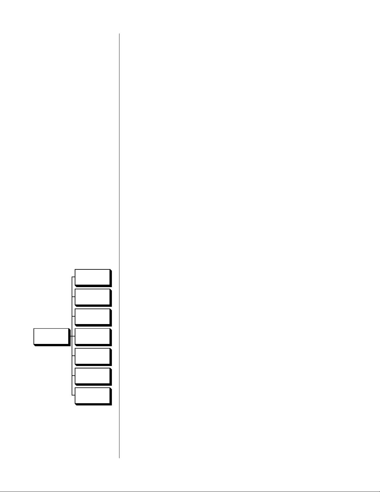
1 UNDER THE INPUT DEFAULTS MENU FOR THE CHOSEN INPUT, SELECT
OFFSET AND PRESS EITHER OF THE VOLUME +/– KEYS
You will see a screen which looks like the following:
input level offset menu
INPUT DEFAULTS
OFFSET 0
2 USING AN APPROPRIATE TEST SIGNAL ON THE SOURCE COMPONENT,
ADJUST THE INPUT LEVEL OFFSET UNTIL THE REFERENCE LED IN THE MAIN
DISPLAY
JUST
ILLUMINATES
Appropriate test signals may be found on: Chapter 5 of Lucasfilm’s WOW!
laserdisc; Track 1 of the Stereophile Test CD; or copies of either of these
sources made on your tape decks or VCRs. (Note that the meters of analog
tape decks such as cassette decks should read -20 dB when recording and
playing back this signal.) Using the volume +/– buttons, adjust the input
level offset up and down as needed until you find the setting at which the
LED first illuminates.
3 PRESS ENTER TO SAVE YOUR NEW DEFAULT INPUT LEVEL OFFSET.
This setting will automatically be used whenever you select this input. You
are, or course, still free to adjust it manually should you run across a recording which was made at an unusual level.
Repeat these programming steps in turn for any inputs which will be used in
your system’s configuration.
Programming Default Modes The PAV also allows you to set up a preferred surround mode for each input,
which will be engaged automatically whenever that input is selected. For ex-
NONE
ample, you might want to use stereo surround for most of your music listening.
As such, it would make sense to set that as your default surround mode for your
CD player and other music sources. Similarly, you would probably choose THX
THX CINEMA
cinema
as your default for a laserdisc player. By doing so, you will automatically
be in the most appropriate surround mode the majority of the time, without hav-
PRO LOGIC
ing to pay any attention to it yourself.
Any surround mode may be assigned to each input. In addition, there is also a
DEFAULT
SURROUND
STEREO
SURROUND
MONO
SURROUND
choice given for none, which will leave the PAV in whatever surround mode it
happens to be in at the time of the input selection. (Note that none is not the
same as surround off which will force the PAV into two-channel stereo operation.)
When the PAV leaves the factory, all inputs use “none” as their default surround
mode, which leaves the PAV in the same mode all the time until you change it
SURROUND
OFF
MONO
manually.
44
Page 45

To change your default surround mode:
1 UNDER THE INPUT DEFAULTS MENU FOR THE SELECTED INPUT, SELECT
“MODE” AND PRESS EITHER OF THE VOLUME +/– KEYS
You should then see a screen which looks something like this:
default surround mode menu
DEFAULT SURROUND MODE
NONE
2 USE THE VOLUME +/– BUTTONS TO CYCLE THROUGH THE AVAILABLE
SURROUND MODES UNTIL YOU SEE THE ONE YOU WOULD LIKE TO HAVE
AS A DEFAULT FOR THIS INPUT.
For example, for your CD player you may want to select the stereo surround mode, as shown below.
DEFAULT SURROUND MODE
STEREO SURROUND
3 PRESS “ENTER” TO SAVE THIS DEFAULT SURROUND MODE FOR THIS INPUT.
Repeat these programming steps in turn for any inputs which will be used in
your system’s configuration.
Programming Video Inputs Video sources have the same input default options outlined above for audio
sources, with one addition: you need to tell the PAV whether you are using the
composite or the S-video inputs for each of your four video inputs. The very different nature of these two signals requires that on screen displays for each be
generated differently. (If set incorrectly, the blue field against which the characters
are normally displayed will be gray; also, color video will turn black and white
for the duration of on screen messages. No real harm is done, but you may wonder why you occasionally lose color.)
video input defaults menu
All video inputs are set to composite when they leave the factory. We strongly
recommend that you standardize on either composite or S-video and use your
choice consistently throughout the system. To use the S-video connection on the
PAV for a particular video input:
1 FROM THE SETUP MENU, SELECT INPUT DEFAULTS, FOLLOWED BY VIDEO
INPUTS, FOLLOWED BY THE INPUT YOU WOULD LIKE TO PROGRAM.
Assuming you have already performed the adjustments outline above, your
on screen menu might look something like the following (the specifics will
vary, of course):
INPUT DEFAULTS
ALIAS LASER
OFFSET -4
MODE THX
VIDEO COMPOSITE
45
Page 46

2 USING THE MASTER BUTTON, MOVE THE CURSOR DOWN TO VIDEO;
THEN PRESS EITHER OF THE VOLUME +/– KEYS TO TOGGLE TO S-VIDEO
3 PRESS ENTER TO SAVE YOUR CHANGE.
Repeat these programming steps in turn for any inputs which will be used in
your system’s configuration.
Mode Defaults The PAV also allows you to customize its default configuration for each surround
mode. Although the most accurate reproduction will be achieved by leaving these
adjustments disabled, their inclusion does allow you the option of tailoring the
sound of various surround modes to suit your individual taste. For example, if
you find yourself turning up the rear speakers whenever you watch a movie, and
then turning them back down to their normal, calibrated setting for music, you
may want to set the defaults for THX cinema and stereo surround accordingly.
We recommend living with the PAV and using it in its calibrated
settings for a while before changing these defaults. There is an adjustment period people go through when their system is upgraded
during which it is difficult to make an accurate decision about
sound quality. The best-known example of this is when someone
first owns a high quality subwoofer: the tendency is to turn it up
too loud initially (so one can “hear it”); as time goes by, most
people find themselves gradually turning it down until it is adjusted to a more accurate level that blends appropriately with the
rest of the system. Similarly, there is a tendency to exaggerate the
bass and surround channels in surround systems before one adjusts to the multichannel experience.
Remember that ad hoc adjustments (to compensate for a poor recording, for example) on the PAV are easy to make. Simply touch the button for the speaker(s)
you wish to adjust, and then raise or lower the volume. These offsets from the
calibrated settings remain active until you deliberately change them, or until you
press recall to restore the PAV to its calibrated settings.
The surround mode defaults simply automate this process. For each of the six
surround modes of the PAV, you may create default offsets for center, rear, and
sub channels. The PAV will simply enter these default settings for you as it
switches from one surround mode to the next. As always, you may alter these settings as you see fit from the front panel or from the remote control. You may also
return to the calibrated (no offsets) setting by pressing recall.
In addition, you may elect to automate the sub on/off toggle described in the
section Programming the Remote Control. (Briefly, this toggle switches between
the speaker setup described in the set speakers menu and one in which the
front speakers are given a full range signal and the subwoofer is turned off.)
Setting Mode Defaults To change the default offsets for your various surround modes, you must first en-
able this special feature for all six surround modes, then alter each as you like:
46
Page 47

**DISABLED/
ENABLED**
1 FROM THE SETUP MENU, SELECT “MODE DEFAULTS” AND ENABLE THE
FEATURE
After selecting mode defaults from the setup menu, you will see a screen
that looks like this:
MODE
DEFAULTS
THX CINEMA
PRO LOGIC
STEREO
SURROUND
MONO
SURROUND
SURROUND
OFF
MONO
MODE DEFAULTS
➔ --DISABLED- THX CINEMA
PRO LOGIC
STEREO SURROUND
MONO SURROUND
SURROUND OFF
MONO
You must first engage this feature by pressing volume +/– to toggle
-- DISABLED-- to --ENABLED--. This extra step ensures that any automated
changes of output levels are consciously chosen and therefore less likely to
cause surprise. It also allows you to disable all the surround mode defaults
in one easy step should you decide at some future date to return to the
calibrated settings for all your routine listening.
2 SELECT THE SURROUND MODE YOU WOULD LIKE TO MODIFY
When you have selected the THX cinema mode, for example, you should
see a screen that looks something like this:
MODE DEFAULTS
SUB ON/OFF NONE
CENTER LVL 0
REAR LVL 0
SUB LVL 0
THX CINEMA
3 SELECT “NONE”, “ON”, OR “OFF” AS THE SETTING FOR YOUR SUBWOOFER
IN THIS SURROUND MODE
If you simply leave this setting as none for all your surround modes, the
PAV will always use the speaker settings from the set speakers menu. If you
prefer to add a subwoofer for movies and remove it when listening to music, you should set speakers for a biamplified system (crossover on), set the
movie-related surround modes for sub on, and set the music-oriented surround modes to sub off. This way, your subwoofer will automatically be engaged or disengaged as you change between (for example) THX cinema to
stereo surround.
4 ADJUST THE LEVEL OF CENTER, REAR AND SUB CHANNELS RELATIVE TO
THE FRONT LEFT AND RIGHT SPEAKERS TO SUIT YOUR PREFERENCE
Using the master button, move the cursor to the item you wish to adjust;
then adjust the setting with the volume ± buttons.
47
Page 48

5 PRESS “ENTER” TO SAVE YOUR CHANGES; REPEAT FOR ALL OTHER
SURROUND MODES AS NEEDED
Note that if you change only a single surround mode, the others will remains at their factory default settings of no offset and sub = none. This will
cause even offsets entered at the front panel to be reset to all zeros when
surround modes other than the one you changed are selected. (All the
more reason to live with the system for a while before electing to customize
it in this way. You should know your preferences with a fair degree of certainty before automating them to this degree.)
Programming the IR Input The infrared remote input jack on the rear panel of the PAV may be pro-
grammed to respond to either local commands (e. g., duplicating the function-
ality of the IR receiver in the main display) or remote commands (e.g. , from
an IR repeater, to affect only the remote signal path). Refer to p. 19, Remote IR
and Remote Turn-on, for more information.
The factory default setting is remote. If your installation of the PAV prevents IR
commands from reaching the PAV (as when behind closed doors, for example),
and if you are using an IR repeater to pass IR commands to the PAV, you may
wish to set the IR input on the rear panel to local, in which case you would also
want to “hard-wire” the PAV to your IR repeater (see IR Tip Polarity, page 20).
To make this software change, follow these steps:
1 ENTER THE REMOTE CONTROL MENU
This menu is accessed from the setup menu by moving the cursor to
remote control (using the master button), and pressing the volume +/– key
to select the menu item.
2 SELECT REAR IR JACK
Using the master button, move the cursor to rear IR jack and press
volume +/–.
3 TOGGLE THE MENU ITEM FROM REMOTE TO LOCAL
Press either of the volume +/– keys to change the default setting of
remote to local.
Important: Note that this change will not take effect until you back out of
the on screen menus and return to normal operation. This
delayed response allows you to continue to use the IR
receiver on the main display long enough to finish what you
are doing. It will be turned off in favor of the IR input jack
once you leave the menu system.
48
Once the rear IR jack is changed to local, the IR receiver in the main display is
deactivated in favor of the rear IR jack. If you do this unintentionally and are not
set up to “hard-wire” the commands into the rear IR jack, don’t worry. You can
always use the front panel buttons to operate the on screen menu system, turning the rear IR jack setting back to remote. Doing so reactivates the IR receiver in
Page 49

the main display. (See Operating the On Screen Menus from the Front Panel,
page 37.)
Changing the
PAV’s IR Address
Important! If you change the IR address of your PAV, your remote
Configuring the
Remote Trigger output
In some installations, you may discover that some other company is trying to
use the same infrared control codes used by the PAV, or vice versa. (This unfortunate circumstance has become more common in recent years thanks to
the explosion of IR-controlled products in the home.) Fortunately, the PAV allows you to use any of eight different sets of IR codes, which are accessed by
changing the “IR address” used by the PAV.
control will no longer operate the PAV until it is re-taught all
of the new codes! Do not change this setting from its default
value of 5 unless you must, in order to solve a conflict.
If you run into an apparent IR conflict where pushing one button on a remote
control affects something seemingly unrelated, we suggest that you contact your
dealer/installer for assistance. (The numbers 0 through 7 refer to Philips RECS80
addresses, a bit of engineering trivia your installer may need if your system is
already using several of the available addresses, including the one we normally
use in the PAV: 5.)
The remote trigger output on the rear panel of the PAV is normally used to auto-
matically turn the associated Proceed AMPs on and off with the PAV. This is particularly convenient when the amplifiers are located at some distance from the
PAV, as may be the case when they are placed near the speakers (for example). In
this application, you can simply leave it in its default setting, pulse.
If you need to turn on and off a power amplifier that does not include remote
turn-on capabilities, the simplest solution is to use a product like the Niles IPC-6,
which is an intelligent AC-outlet strip that can turn AC power on and off to a set
of components based on the presence or absence of a level control voltage.
Caution! If you use the remote trigger output of your PAV with non-
Madrigal products, it is important that those products provide
current-limiting and ground isolation for this output. This
isolation may be accomplished with opto-couplers or with
low-voltage relays. Please consult with your installer prior to
using the remote trigger output with products other than those
designed by Madrigal.
Note that the remote trigger output of the PAV can support approximately 5 volts
at 30 mA current.
Having completed the calibration of your PAV system, you may also wish to consider locking your settings to minimize the likelihood of someone inadvertantly
changing your setup. This menu item can be found under the operate menu,
which is found at the main PAV men u. (See page 51 for more information.)
49
Page 50

Using the PAV
Setting the Volume There are, in effect, two volume controls in the PAV. When in either THX cin-
ema
or pro logic modes, the input level control should be used to compensate
for differences between recordings, using its associated green LED as a guide.
Adjustments to allow for personal preferences, late-night listening, and the like
should then be made with the master volume control.
When in any of the other surround modes, the input level adjustment is significantly less critical and can be largely ignored (particularly if input level defaults were set up during installation).
Home THX cinema When the THX cinema mode is engaged, both the Dolby Pro Logic circuitry
and the proprietary Home THX audio processing circuits are in use. This is
most appropriate for film-based program materials made since the mid-1970’s,
which have in all likelihood been mixed in a standard dubbing stage environment. This setting will provide the listener with the most accurate reproduction of the majority of motion pictures available. In addition, many other video
source materials are produced in Dolby Surround using the industry standard
response curves, and are best enjoyed in the THX cinema mode. (Examples
include Star Trek: Voyager and The David Letterman Show, which are mixed in
an environment which emulates the dubbing stage used for film.)
Dolby Pro Logic Surround Some program material does not conform to film industry standards, although
it may still be Dolby Surround encoded. Music videos on MTV, for instance,
are often Dolby Surround encoded, but have soundtracks which are produced
in non-film studios. In fact, a growing number of music CDs are mastered with
surround sound. These sources and others which have surround encoding but
which are unlikely to have been mixed or re-mixed in industry-standard production facilities should use the pro logic mode to avoid compensation where
none is indicated.
When in doubt as to whether THX cinema or pro logic is more appropriate,
listen for a natural presentation of the treble. Films mixed for theatrical release
exhibit an elevated treble region when played back on a home system with
flat response. The THX cinema mode will correct this. Conversely, surround-
encoded programs without this high frequency emphasis might sound dull or
lacking in detail when (incorrectly) played in the THX cinema mode.
Stereo Surround The stereo surround mode has been carefully designed to extract real ambi-
ence from your recordings rather than synthesizing something artificial that
might be quite alien to the music itself. The ambient cues found in the program material are then used to provide appropriate information for the center
and rear speakers. The front Left and Right speakers are left unaffected by this
mode, allowing you to hear unadulterated stereo imaging with the addition of
a genuine sense of hall ambience.
50
Since this mode is based on the recordings themselves, it is normal to hear
some variation in the degree of the effect. Extremely “dry” recordings which
lack any significant ambience may not sound significantly different than when
Page 51

in surround off mode (e.g., two-channel stereo). You may find that increasing
the level of the rear speakers is necessary in order to bring what little ambience is in a “dry” recording up to a more enjoyable level.
Mono Surround The mono surround mode can provide a sense of spaciousness and size to
monophonic program material such as some historical recordings and movie classics such as Casablanca or The Wizard of Oz. The
mono surround mode makes
no effort to “electronically reprocess to simulate stereo” (a process which almost
always causes more harm than good). Instead, it uses sophisticated steering techniques to create a sense of space in what would otherwise be a largely dimensionless soundfield. It is particularly helpful when viewing mono program material on a big screen, where a tiny mono image would simply sound wrong in
contrast to the big picture.
Surround Off The surround off mode is intended for music reproduction without any form of
surround enhancement. In this mode, the Left and Right speakers are active along
with the subwoofer(s), and reproduce the input without any processing other
than the electronic crossover needed for the subs.
Mono The mono mode sums the incoming Left and Right signals. The result is sent to
the center channel speaker, as well as the subwoofer(s). This mode is especially
useful for older, classic films or historical recordings which have noisy mono
soundtracks. Since much of the noise is likely to be random in phase, significant
noise cancellation can often be achieved by playing these mono sources in a true
mono mode.
OPERATE
The Operate Menu Those settings for which there is no “right” or “wrong” but which are purely a
matter of user preference are contained in the operate menu (accessed from out-
side the menu system by pressing menu on your remote control twice). The op-
MUTE
LEVEL
erate menu
• mute level — the magnitude of volume reduction introduced by pressing
is organized as shown at left, and is detailed below:
the mute key is user-definable from -5 to -110 in increments of 5 (-2.5 dB to
-55 dB in 2.5 dB increments). The factory preset is for -40 (-20 dB).
• display pref — the display preferences subheading groups together several
DISPLAY
PREF
items which control the appearance of the on screen displays presented by
the PAV during use. We will cover to this menu item in detail on the next
page.
• volume display — gives you the option of displaying your volume settings
VOLUME
DISPLAY
on a scale of 0 (off) to 112 (extremely loud) or on a scale which is marked
off either plus or minus around the calibrated reference level established
during calibration. The former is called “absolute” while the latter is called
“relative.” As an example, if your calibrated reference level is 91, the display
VOLUME
SPEED
would read 0 in the relative mode when it would read 91 in the absolute
mode.
• volume speed — you may select either slow, medium, or fast response for
the volume change when pressing and holding the volume +/– keys. In all
SETUP:
UNLOCKED
cases, single taps of the volume keys result in single incremental steps in
volume. The volume speed chosen affects the amount of time it takes to reach
maximum speed while holding the volume +/– button down.
• setup: locked/unlocked — after having completed all setup adjustments,
you may wish to lock your settings to prevent accidental changes. Doing so
will disallow access to the main setup menu until unlocked.
51
Page 52

The Display Pref Menu Returning to the subject of display preferences, selecting this menu item (by
pressing either volume +/– while the cursor is pointing at it) presents you with a
sub-menu, outlined at left. The details of that submenu are as follows:
DISPLAY
PREF
DISPLAY
POSITION
DISPLAY
TIMEOUT
CHARACTER
STYLE
BACKGROUN
D COLOR
• display position — the position of the on screen display of volume
changes, surround mode changes, etc., can be moved up or down to
suit the needs of your system. This flexibility allows you to place your
PAV’s on screen information where it won’t conflict with other on
screen information. As an example, you may place the on screen display in the black area under letterboxed movies.
•
display timeout — controls the duration of these on screen “updates”
generated by the PAV as status reports when you change something.
(Remember that you can disable the on screen display using the on
screen
button on the remote control.)
• character style — on screen messages are normally displayed within
a black box when superimposed on live video signals. This display
method ensures legibility even against extremely bright backgrounds,
when white letters might otherwise be difficult to read. At your option, however, you may elect to have these superimposed messages
displayed with only a black fringe around them, which some may find
less intrusive than the black box. This method remains easily legible
in all cases except a few (relatively rare) examples of extremely bright
video. A case in point might be the seemingly endless pans across the
sky shown during broadcast golf tournaments. (Do they really think
we can see a tiny white ball flying across a cloudy sky?).
• background color — the default color for the screen when lacking a
live video signal to display is blue. This blue screen serves as a reminder that your television is on, when in fact you may prefer to turn
it off. However, some may prefer to leave their projection television on
in order to keep it warmed up and ready to use, in which case a
black screen might be more desirable. (A black screen would facilitate
listening to music in a darkened room, for example.) This menu item
allows you to choose the best mode for your system, either blue or
black.
52
Page 53

Programming and Using the
Remote Control
The PAV/PDSD is equipped with a powerful backlit remote control that will
control up to seven additional devices, in addition to all the features of the
PAV. It may also be programmed to “learn” the functions from most current
infrared remote controls. This means that once programmed, the PAV/PDSD
remote will not only operate your PAV, but most TV sets, VCRs, DVD and LD
players, satellite systems, set-top converters and other IR controlled home
theater or home automation equipment.
pre-programmed functions To operate the PAV, be certain that you have pressed the pav/audio Device
Control Selector. Note that the Programming Status LED will briefly blink red
and the LCD Display will confirm your selection by switching to AUDIO. In this
pre-programmed mode, the remote control takes on the functions of the PAV.
learning set-up In addition to it’s preprogrammed functions, the PAV/PDSD remote may be
taught to learn the commands from almost any infrared remote that is used to
operate audio, video, home theater or home automation equipment. This enables
the PAV/PDSD remote, once programmed, to replace a collection of remotes, and
operate your entire entertainment system from one, powerful command center.
The PAV/PDSD remote has the ability to learn new functions from your original
remote controls:
• There are 8 “pages” of learning with each page corresponding
to the 8 Device modes on the Remote control: pav/audio, cd,
dvd, aux, sat, tv, vcr and cbl.
• All buttons in all Device modes can learn, except the light button.
• The 8 Device buttons at the top of the remote control labeled
(pav/audio, cd, dvd, sat, tv, vcr and cbl) learn only in the Audio
mode.
• Learned functions override any existing preprogrammed functions
on the remote control.
• Learned functions are automatically erased when a new function is
learned on the same button.
• To erase a learned function and return to an original
preprogrammed function, please refer to the section Erasing Learned
Functions.
NOTE: If you inadvertently overwrite one or more pre-programmed PAV com-
mands in your PAV remote control, the PAV itself can send all of the necessary IR
commands from its main display window, enabling you to teach the PAV remote
both its pre-programmed commands and a few other, optional commands which
you might find useful. (Please refer to the section “Programming PAV Functions”.)
53
Page 54

learning new functions on the
main keypad
1 Select the mode in which you wish to learn the new function
by pressing the corresponding Device button.
2 Place the PAV/PDSD remote and the original remote control to
be learned from, on a flat surface. Line up the remote controls
head-to-head, about two to three inches apart.
rev fwd
mute
input
stop
volume
pause
prev
volume
play
next
audio
pav
standby
power
record
cd dvd aux
adjust channel
cblvcrtvsat
2" to 3"
Device Buttons
pav
audio
power
standby
input
mute
prev
rev fwd
stop
Play Button
cd dvd aux
adjust channel
record
volume
play
volume
pause
3 Press and hold both the Device button selected in Step 1
and the play button for about three seconds, until the LCD on
cblvcrtvsat
NOTE: Each of the following steps must be completed within 20 seconds. If
the PAV remote shows LEARN. the PAV remote is now in the
learning mode.
the remote does not receive any new commands within the allotted time, it
next
will return to its normal operating mode.
4 Press and release a button on the PAV remote you have
selected to learn the new function. The LCD will show READY.
5 Press and hold the button on the original remote control for
about 3 seconds from which you are learning the new function.
The LCD on the PAV remote will show – – – – indicating that it is
receiving the information from the original remote control.
6 Release the button on the original remote control. The LCD on
the PAV remote will show RETRY.
7 Press and hold the same button on the original remote once
again, for about three seconds. The LCD on the PAV remote
will flash GOOD, the Device Mode and then return to LEARN,
verifying that the new function has been learned.
Repeat Steps 4 through 7 for any other buttons you wish to learn new
functions.
54
8 Once you have completed the learning for all the desired but-
tons in a Device mode, store the learned functions by pressing
the device and play buttons simultaneously, once again. The
LCD in the PAV remote will show SAVED and then return to
the Device Mode. The remote has now returned to the original
operating mode.
Once you have stored the learned functions, test the buttons that have been
taught. If any of the buttons do not operate as they should, please repeat from
Step 1 for those buttons.
NOTE: If the LCD shows FAIL at any time during the learning process, the PAV
remote was unable to learn the new functions. Please repeat from Step 4. If
the remote continues to show FAI L during the learning process, please try the
following suggestions:
Page 55

• Increase or decrease the head-to-head distance between the
two remote controls, within a 1 to 5 inch range.
• Increase or decrease the time you press-and-hold the button on
the original remote control in step 5, for 1 to 2 seconds.
• Avoid fluorescent lights or strong sunlight during the set-up.
These lighting conditions can cause interference with the
learning process.
• Verify that the original remote control contains fresh batteries.
Some remote controls operate at non-standard IR, UHF or ultrasonic frequencies,
and are unable to be learned. If you continue to experience difficulty during
set-up, please contact authorized dealer for assistance.
learning new functions
on device buttons
The eight Device buttons at the top of the remote control can also learn new
functions. These buttons can only be set up in the Audio mode. If a new function is learned on a Device button, the new function will override any existing
preprogrammed information on the Device button.
1 Place the PAV remote and the original remote control to be
learned from, on a flat surface. Line up the remote controls
head-to-head, about two to three inches apart.
2 Press-and-hold both the audio and play buttons simultaneously,
for about three seconds, until the LCD on the PAV remote shows
LEARN. The PAV remote is now in the learning mode.
NOTE: Each of the following steps must be completed within 20 seconds. If the
remote does not receive any commands within the allotted time, it will return
to its normal operating mode.
3 Press-and-release one of the eight Device buttons on the PAV
remote. The LCD will show READY.
4 Press-and-hold the button on the original remote control you
wish to teach into the PAV remote, for about three seconds.
The LCD on the PAV remote will show – – – – indicating that it
is receiving the information from the original remote control.
5 Release the button on the original remote control. The LCD on
the PAV remote will show RETRY.
6 Press-and-hold the same button on the original remote again,
for about three seconds. The LCD on the PAV remote will flash
GOOD, the Device Mode and then return to LEARN, verifying
that the new function has been learned.
Repeat Steps 3 through 6 for any other buttons you wish to learn new
functions.
7 Once you have completed the learning for all the desired
Device buttons, store the learned functions by pressing the
audio and play buttons simultaneously, once again. The LCD
in the PAV remote will show SAVED and then return to the
AUDIO mode. The remote has now returned to the original
operating mode.
55
Page 56

erasing learned functions
To erase learned functions, please refer to the following procedures:
Erasing Individual Buttons:
1 Press the Device button for the mode where the learned function
has been stored.
2 Press-and-hold the Device and the play buttons simultaneously,
for about three seconds, until the LCD shows LEARN.
3 Press-and-release the button to be erased. The LCD will show
READY.
4 Press the light button. The LCD will flash ERASE, CLEAR, the
Device Mode and then return to LEARN.
Repeat steps 3 and 4 for any other buttons to be erased.
5 To return to the normal operating mode, press the Device and
play buttons simultaneously.
The learned functions on the selected buttons have now been erased.
The pre-programmed functions for these buttons will now operate on the
remote control.
Erasing All Buttons in One Device Mode:
1 Press the Device button for the mode to be erased.
2 Press-and hold the Device and play buttons simultaneously,
for about three seconds, until the LCD shows LEARN.
3 Press-and-hold the Device and light buttons simultaneously
for approximately five seconds and then release the buttons.
The LCD will flash ERASE and then alternately CLEAR and the
Device Mode.
NOTE: When the LCD on the remote returns to the
Device Mode
, all the learned
functions in the selected Device mode have been erased. All the buttons in that
Device mode will now operate with the preprogrammed functions in that mode.
Erasing All Buttons in All Device Modes:
1 Press-and-hold the tv Device Button and the light button simul-
taneously, for approximately ten seconds. The LCD will flash
ERASE ten times, flash CLEAR and then return to the TV mode.
When the LCD on the remote returns to tv, all the learned functions in all
eight Device modes have been erased. All the buttons in all Device modes
will now operate with the preprogrammed functions in their respective modes.
operation After you have programmed the remote control for your equipment, use the
following procedures to operate your home entertainment system:
1 Press the Device button that you wish to operate: e.g., to operate
a TV press the tv Device button; to operate a VCR, press the vcr
Device button, etc.
56
2 Aim the remote control at the device and press the power/
standby
3 Press the buttons that send out the commands you desire.
button to turn on the device.
Page 57

NOTE: Some audio/video devices have separate buttons for Power On and
Power Off. To operate these devices on the remote, press the corresponding
Device Button to turn the equipment ON and press the power/standby button
to turn the equipment OFF or place the equipment in the Standby mode.
Please try all the functions of this remote control with your equipment. The
most common functions are labeled on the remote. However, some of the
secondary functions might be stored under a button that has a different name
from the one on your original remote control.
device buttons
main device mode
automatic audio mode
Pressing a Device button at the top of the remote performs the following
functions:
1 Changes the Device mode on the PAV remote control.
2 Sends out a Power ON command for the Device, if applicable.
3 Sends out a preprogrammed or learned Audio receiver/
preamplifier INPUT SELECTION, on second press of the buttons
in A–XXX mode, if applicable.
4 Toggles between the Main Device mode and the Automatic Audio
Mode. (See “Automatic Audio Mode” below.)
NOTE: Device buttons can learn new information only in the Audio mode.
When the main Device mode is displayed in the LCD, the PAV remote will
operate in a standard operating mode and all the buttons will operate in the
preprogrammed, learned and punch-through features for that Device mode.
The PAV remote is designed to provide convenient and continuous operation of
your home theater system’s devices. You can have full and immediate access to
the PAV’s volume and surround controls while maintaining control of any of the
other seven different device modes of the remote control by pressing the same
Device button a second time.
The Automatic Audio Mode enables you to watch a video program or listen to
a CD and also adjust audio volume and surround levels in the same Device
mode. The LCD will show a A–XXX indicating that the remote control is in the
Automatic Audio mode.
Example: Pressing the sat Device button a second time will change the LCD
from SAT to A_SAT.
In the Automatic Audio Mode, you gain control of the PAV volume and surround
levels while also maintaining full control of the Channel, Transport cursor and
Numeric Keypad of the device.
57
Page 58

remote control
9
1234
5678
10 11
15121613 14
20
222423
17
18 19
21
25
29 30 31 32
36353433
37
41 42 43 44 45
50
51 52 53 54
55
56
49484746
38 39 40
26 27 28
audio
pav
cd dvd aux
cblvcrtvsat
standby
mute
power
input
prev
record
adjust channel
next
volume
volume
play
rev fwd
pause
stop
vcr1 vcr2 laserdisc THX
tv/vcr1 cd1 cd2 mode
tape1 tape2 bal/aux status
entermenu
46
9
123
5
78
on
screen
display input delay recall
subrearcenterbalancemaster
late night
m1 m2
light
m3
path
m4
tuner
0
function worksheet
Planning Your Remote Control
For your convenience, we have included the worksheets on the following two
pages on which you may plan which additional functions you will assign to
which buttons on the PAV remote control. We suggest photocopying this page
and then planning your programming before getting into it too heavily. Refer to
the drawing below which shows the PAV remote at the left and the PAV remote
at the right with numbers on each button which correspond to the numbers on
the worksheets that follow. Refer to this drawing when learning/programming
additional remotes into the PAV remote control. A little time spent planning can
make the teaching process go much more smoothly, and it provides you with a
ready reminder of which commands you placed where during the first day or
two of use. After that, you will probably find everything to be second nature,
and you may wonder how you ever got along without this “all-in-one” remote
control. An asterisk (*) indicates buttons normally used by the PAV.
58
Page 59

remote control
function reference
no. button name device device device device
1-8 * device name _________ _________ _________ _________
9 * power/standby _________ _________ _________ _________
10 adjust + _________ _________ _________ _________
11 channel + _________ _________ _________ _________
12 * input/mute _________ _________ _________ _________
13 record/ _________ _________ _________ _________
14 adjust – _________ _________ _________ _________
15 channel – _________ _________ _________ _________
16 prev/ _________ _________ _________ _________
17 next/ _________ _________ _________ _________
18 stop/ _________ _________ _________ _________
19 pause/ _________ _________ _________ _________
20 * volume/ _________ _________ _________ _________
21 * volume/ _________ _________ _________ _________
22 fwd/ _________ _________ _________ _________
23 rev/ _________ _________ _________ _________
24 play/ _________ _________ _________ _________
25 * vcr1/1 _________ _________ _________ _________
26 * vcr2/2 _________ _________ _________ _________
27 * laserdisc _________ _________ _________ _________
28 * THX _________ _________ _________ _________
29 * tv/vcr1/4 _________ _________ _________ _________
30 * cd1/5 _________ _________ _________ _________
31 * cd2/6 _________ _________ _________ _________
32 * mode _________ _________ _________ _________
* An asterisk indicates buttons normally used by the PAV.
59
Page 60

no. button name device device device device
33 *tape1/7 _________ _________ _________ _________
34 *tape2/8 _________ _________ _________ _________
35 *bal/aux/9 _________ _________ _________ _________
36 *status _________ _________ _________ _________
37 *menu _________ _________ _________ _________
38 *tuner/0 _________ _________ _________ _________
39 *enter _________ _________ _________ _________
40 *late night _________ _________ _________ _________
41 *on screen _________ _________ _________ _________
42 *display _________ _________ _________ _________
43 *input _________ _________ _________ _________
44 *delay _________ _________ _________ _________
45 *recall _________ _________ _________ _________
46 *master _________ _________ _________ _________
47 *balance _________ _________ _________ _________
48 *center _________ _________ _________ _________
49 *rear _________ _________ _________ _________
50 *sub _________ _________ _________ _________
51 m1 _________ _________ _________ _________
52 m2 _________ _________ _________ _________
53 m3 _________ _________ _________ _________
54 m4 _________ _________ _________ _________
55 light _________ _________ _________ _________
56 *path _________ _________ _________ _________
* An asterisk indicates buttons normally used by the PAV. _________
60
Page 61

punch-throughs
Remote Control
Advanced Features
After you set up the remote control to operate your equipment, you can also
program advanced features on the remote control. The advanced features are
designed to enhance the use of the remote control with your home entertainment system.
volume control
“punch-through”
The PAV/PDSD’s remote may be programmed to operate the volume + – controls
and mute button from either the TV or PAV to operate in conjunction with any of
the eight devices controlled by the remote. For example, since the PAV will likely
be used as the sound system for TV viewing, you may wish to have the PAV’s
volume activated when the remote is set to run the TV. Either the AUDIO or TV
volume control may be associated with any of the remote’s devices.
NOTE: When this feature is active, the AUDIO or TV volume and mute will
override any existing volume controls in that mode.
To program the remote for Volume Punch-Through, follow these steps:
1 Select the mode that you wish to program for Volume Contr ol
“Punch-Through.”
2 Press the corresponding Device button (e.g., tv, sat, etc.) and
the mute button simultaneously. SET will appear in the LCD.
3 Press the adjust + button. PUNCH will appear in the LCD.
4 Press either the pav/audio or tv Device selector, depending on
which system’s volume control you wish to have attached for
the punch-through mode. AUDIO or TV will flash in the LCD.
Example: To have the PAV’s volume control be activated even though the
remote is set to control TV, first press the tv Device control selector, and the
mute button at the same time. Next press the adjust + button, followed by the
pav/audio Device control selector.
To return to the original setting, follow these steps:
1 Select the mode that you want to turn off the Volume Control
“Punch-Through” and press the corresponding Device button
(e.g., tv, sat, etc.) and the mute button simultaneously. SET will
appear in the LCD.
2 Press the adjust + button. PUNCH will appear in the LCD.
3 Press the same Device button again. The Device mode will
flash in the LCD.
The AUDIO or TV Volume Control “Punch-Through” is now turned off. The
VOLUME and MUTE of the original device will operate on the remote control.
61
Page 62

channel control
“punch-through”
You can program the remote so that either the Sat or Cable Channel Controls
(channel + or channel –) will also operate in other modes on the remote control.
NOTE: When this feature is active, the SAT or Cable channel + or channel – will
override any existing channel controls in that mode.
To program the remote for Channel Control Punch-Through, follow these steps:
1 Press the Device button for the device you wish to have associ-
ated with the volume control (e.g., sat or cbl.) and the mute
button simultaneously. SET will appear in the LCD.
2 Press the adjust – button. PUNCH will appear in the LCD.
3 Press either the sat Device button to set-up for the SAT Chan-
nel Control or the cbl Device button to set-up for the Cable
Channel Control. Either SAT or CBL will flash in the LCD,
depending on the Device button selected.
SAT or Cable Channel Controls will now override the original channel + and
channel – in this mode.
To return to the original setting, follow these steps:
1 Select the mode that you want to turn off the Channel Control
“Punch-Through” and press the corresponding Device button
and the mute button simultaneously. SET will appear in the
LCD.
transport control
“punch-through”
2 Press the adjust – button. PUNCH will appear in the LCD.
3 Press the same Device button again. The Device mode will
flash in the LCD.
The SAT or Cable Channel Control “Punch-Through” is now turned off. The
CHANNEL UP and DOWN of the original device will operate on the remote
control.
You can set up your remote control so that VCR or CD Transport Controls (Play,
Stop, Fast Forward, Rewind, Pause and Record) will also operate in other modes
on the remote control. An example would be to control your VCR functions
while operating the remote control in the tv mode.
NOTE: When this feature is active, the VCR or CD functions (Play, Stop, Fast
Forward, Rewind, Pause and Record) will override any existing functions
preassigned to these buttons in than mode.
To program the remote for Transport Control Punch-Through, follow these steps:
1 Press the Device button for the device you wish to have associ-
ated with the volume control (e.g., tv or sat.) and the mute
button simultaneously. SET will appear in the LCD.
62
2 Press the play button. PUNCH will appear in the LCD.
Page 63

memory buttons There are five memory buttons (m1~m4, power/standby) that are designed to
power
standby
input record
mute
Memory Buttons
adjust channel
3 Press either the vcr Device button to set-up for VCR Transport
Control or the cd Device button to set-up for CD Transport
Control. VCR or CD will flash in the LCD, depending on the
Device button selected.
The VCR or CD Transport Controls (Play, Stop, Fast Forward, Rewind, Pause
and Record) will now override the original functions of the buttons in this
mode.
To return to the original setting, follow these steps:
1 Select the mode that you want to turn off the Transport Control
“Punch-Through” and press the corresponding Device button
and the mute button simultaneously. SET will appear in the
LCD.
2 Press the play button. PUNCH will appear in the LCD.
3 Press the same Device button again. The Device mode will
flash in the LCD.
The VCR or CD Transport Control “Punch-Through” is now turned off. The
original functions assigned to these buttons are restored.
store up to 15 commands in each button. Pressing any one of the memory
buttons will send out the series of commands that are stored in that button.
You can either turn on or off up to eight devices by storing Power on/off
commands or use it to select the favorite channels by storing channel numbers
into the button. You can also combine Power on/off, select favorite channel
and any of the features in the remote control to these buttons.
m1 m2
m3
m4
light
path
You can program any of the memory buttons (m1~m4, power/standby) in
AUD mode and it will send out the stored commands in Audio, CD, DVD and
AUX modes. You can also program the memory buttons in SAT mode, and it
will send out the stored commands in Satellite, TV, VCR and CBL modes.
• MACRO COMMANDS:
Memory Buttons can store and emit up to 15 commands including multiple
Power On/Off sequences. As an example, in the Audio mode, the power/
standby
Memory Button can be programmed to turn on the TV, turn on the
PAV, turn on the VCR and turn on the Satellite receiver with one button push.
• FAVORITE CHANNELS:
Memor y Buttons can provide direct access to your channel with a one-button
push. As and example, in the SAT device mode each of the Memory Buttons m1,
m2, m3 and m4 can provide direct access to a different satellite channel by send-
ing out the three-digit channel number for that channel to your satellite receiver
with a one-button push.
63
Page 64

programming
memory buttons
To program the Memory Buttons, follow these steps:
1 Select the section that you wish to program the Memory Button
in by pressing the corresponding Device button (audio or sat)
and mute button, simultaneously. SET will appear in the LCD.
2 Press one of the Memory Buttons (m1, m2, m3, m4 or power/
standby
) into which you wish to store the functions. M(1-5)_##
will appear in the LCD.
NOTE: The mute button is used to designate POWER/STANDBY commands
during Memory button programming.
3 Press in up to fifteen commands that you want stored in that
Memory button. Each successive button selection will appear
as M(1-5)_(01-15) in the LCD.
You can select functions from another mode by first pressing
the corresponding Device button and then the buttons where
those functions are located in that mode. The pressing of a
Device button also counts as one command.
NOTE: Each insertion of a Device Button adds a 1/2-second delay to the
command sequence.
4 Press the channel + button to store your selections. SAVE will
flash three times in the LCD to confirm the programming.
IMPORTANT NOTE: If you attempt to store more than 15 commands, the entire
sequence of macros entered will clear and you will need to start over.
NOTE: It can take up to 15 seconds to send out 15 commands from a memory
button. Please continue to point the remote control at the device(s) until all the
commands on the Memory Button have been sent out. This will ensure that all
the commands are received by the device(s).
Example: To program your TV, Cable Box and the PAV to turn on when the
power button is pressed, first press-and-hold the sat and mute buttons until SET
appears in the LCD. Next, press the mute button to enter the Power commands
for the PAV. Press tv to select the TV mode, and then press the mute button
again, to select TV Power. Finally, press cbl followed by the mute button to
select Cable power. Press the channel + button to enter the commands.
After following these steps, each time you press the power/standby button,
after either the sat, tv, vcr or cbl Device control selector has been pressed, the
remote will send the “Power On/Off” command.
64
Page 65

erasing memory buttons
To erase the Memory Buttons, follow these steps:
1 Select the mode (AUD or SAT) in which you want to erase the
Memory button.
2 Press the corresponding Device button (audio or sat) and mute
button simultaneously. SET will appear in the LCD. Press the
Memory button to be erased.
3 Press the channel + button. SAVE will flash in the LCD. The
M(1-5)_## will appear in the LCD.
Memory button is now erased.
NOTE: Any previously stored commands on a Memory button will be erased
when new commands are stored on the same Memory button.
changing the lcd display Twenty-four different LCD displays can be selected for each Device mode of
the remote control. To select an alternate LCD display, please use the following
procedure:
1 Press-and-hold the Device button for which you would like to
change the LCD setting.
2 While pressing the Device button, press-and-release the pause
button. Each time the pause button is pressed, the LCD will
show one of twenty-four displays.
3 Release the Device button when you find the new LCD display
you wish to assign to the Device mode.
• CHOICE OF LCD DISPLAYS
TV VCR CABLE SAT AUDIO CD
DVD AUX TV2 VCR2 TUNER AMP
TAPE1 TAPE2 WEBTV SURR DAT PROJE
AUX2 LD AUD2 LIGHT DSS AV
• LCD DISPLAYS IN THE AUTOMATIC AUDIO MODE
A-TV A-VCR A-CAB A-SAT AUDIO A-CD
A-DVD A-AUX A-TV2 S-VC2 A-TUN A-AMP
A-TA1 A-TA2 A-WEB A-SUR A-DAT A-PRJ
A-AX2 A-LD A-A2 A-LIT A-DSS A-AV
65
Page 66

Programming PAV Functions If you inadvertently overwrite one or more PAV commands in your PAV remote
control, never fear—you don’t have to obtain another PAV remote in order to
re-teach your own its PAV-specific commands. The PAV itself can send all of
the necessary IR commands from its main display window, enabling you to
teach the PAV remote both its pre-programmed commands and a few other,
optional commands which you might find useful.
When using the PAV itself to teach new commands to your remote control,
your remote will have to be in its learning mode (obviously). Therefore, you
must navigate the on screen menus by using the buttons on the front panel of
the PAV. The buttons on the front panel you need to use are as follows:
•
recall: the menu function is provided by the recall button. In
order to activate the on screen menus rather than simply recalling the calibrated output level settings, press and hold the recall
button until the front panel lights are turned off (about ten seconds). From this point on until you exit the menu system, the
recall button will perform exactly as the menu button on the remote control would.
• master: the front panel master button is also conveniently
placed adjacent to the volume +/– buttons, and serves the same
purpose as the one on the remote control.
• volume +/–: the front panel volume +/– buttons also operate in
the same fashion as their counterparts on the remote control.
• standby: the enter function is provided by the standby button
on the front panel (when the PAV is in menu mode). It is deliberately set apart from all of the other menu-related buttons to
PANEL
BUTTONS
PRESS
BUTTON
make permanent changes of system parameters a deliberate act.
TEACH
REMOTE
REMOTE
ONLY
DIRECT
ACCESS
SPECIAL
MENU
ENTER
DISPLAY
ON SCREEN
THX
STATUS
LATE NIGHT
DUAL DRIVE
TOGGLE
SURROUND
MODES
PATH
MISC
CONTROL
CONTROL
TRIG 1 ON
CONTROL
TRIG 1 OFF
CONTROL
TRIG 2 ON
CONTROL
TRIG 2 OFF
SUB/
CROSSOVER
1 ENTER THE SETUP MENU
2 SELECT “REMOTE CONTROL,” AND THEN “TEACH REMOTE”
3 TO RE-LEARN THOSE FUNCTIONS WHICH HAVE CORRESPONDING
FRONT PANEL BUTTONS, CHOOSE “PANEL BUTTONS”
The on screen display will prompt you to press any button. Line up the
IR window of the PAV remote control with the center of the main display
of the PAV, at a distance of approximately 6"-12". Select the to-be-learned
button on the remote, then press the corresponding button on the PAV.
Notice that a yellow LED in the main display lights up briefly after you
press a button. This LED indicates that the PAV is transmitting the command which corresponds to the button you just pushed. You may repeat
this process until all buttons have been learned.
Tip : save the teaching of the
recall
button for last, since its function as the menu button’s “double” will result in the on screen
display reverting to the previous menu after it transmits its
signal.
4 TO RE-LEARN BUTTONS WHICH EXIST ONLY ON THE REMOTE
CONTROL, CHOOSE “REMOTE ONLY”
From the teach remote menu, select remote only. The on screen display
will now look something like this (see next page):
66
Page 67

remote only menu
REMOTE ONLY
TEACH
REMOTE
PANEL
BUTTONS
REMOTE
ONLY
DIRECT
ACCESS
SPECIAL
MENU
ENTER
DISPLAY
ON SCREEN
THX
STATUS
LATE NIGHT
DUAL DRIVE
TOGGLE
MENU
ENTER
DISPLAY
ON SCREEN
THX
STATUS
LATE NIGHT
DUAL DRIVE TOGGLE
Press the appropriate button on the remote control (while in learning
mode), and then use the front panel master and volume +/– buttons to
select and “fire” the appropriate IR command from the main display of
the PAV into the remote control. Repeat as necessary.
5 TO LEARN COMMANDS THAT GIVE DIRECT ACCESS TO SURROUND
MODES, SIGNAL PATHS, AND POSITIVE CONTROL OVER TOGGLE
FUNCTIONS, SELECT “DIRECT ACCESS” ON THE TEACH REMOTE
MENU
You may also teach special commands to the PAV remote control which
allow direct access to the various surround modes, signal path and control options. These may be assigned to any available button on the PAV
remote control.
For example, you may find that you use the THX cinema, pro logic,
stereo surround and surround off modes most frequently. You could as-
sign a button to each of these and never have to cycle through the other
options again. Definite “on” and “off” commands for standby and mute
(rather than toggles) offer improved control over the PAV when operated
from a remote zone, or when controlling the system via a macro.
surround, path and
misc control menus
The Surround, Path and Misc Control menus under the Direct Access
menus are as follows:
SURROUND PATH MISC CONTROL
PRO MAIN OPERATE
STEREO S REMOTE STANDBY
MONO S BOTH MUTE ON
SUR OFF RECORD MUTE OFF
MONO DIRECT VOLUME
Press the appropriate button on the remote control (while in learning
mode), and then use the front panel master and volume +/– buttons to
select and “fire” the appropriate IR command from the main display of
the PAV into the remote control. Repeat as necessary.
67
Page 68

Room Acoustics
The following information on room acoustics does not need to be considered
in every installation. Rather, it is provided for those who plan a dedicated listening room, or for those who feel they have a problematic room and therefore need ideas about how to improve their system’s performance further.
Once again, the value of your dealer’s experience should never be underestimated. Many installers have been involved in dozens or hundreds of home theater installations similar to yours, and have proven solutions to whatever problem
you might be experiencing. The information provided here is best used as a
starting point for your discussions with your dealer.
Room Reverberation In a perfect world, your room would have no characteristic sound of its own, no
acoustical “fingerprint.” The ideal room would be perfectly neutral and would not
superimpose itself on the sound within it in any way. After all, any reverberation
or ambient sound which the director wished people to hear will be recorded in
the soundtrack. And much of the inherent ambience in music recordings will
normally be reproduced by the rear speakers (using the stereo surround mode),
where such ambience belongs. Anything beyond this added by the room would
be redundant and would actually detract from the realism. In general, then, the
ideal listening room will be somewhat more “dead” acoustically than the average
living room. This goal can be accomplished through the use of drapes, plush carpeting, or various acoustical treatments.
Note, however, that the surround speakers depend on reflecting sound to develop
the proper enveloping characteristic, and that they therefore need some reflective
surfaces. Ideally, these would be diffusive in nature, providing randomized reflections in many directions. Bookcases and other irregular surfaces provide diffusion, as do some commercially-available wall treatments. If there is some degree
of choice in the matter, it is generally better to have the rear 1⁄3 of the room be
reflective and diffusive, while the front 2⁄3 of the room is relatively absorptive. Re-
sist the temptation to “go overboard,” however, lining the room with absorptive
material from floor to ceiling. It is possible to have too much absorption, resulting
in reduced subjective dynamic impact and therefore less excitement.
The Boundary Effect A well-known effect of room acoustics is the change in bass and mid-bass re-
sponse which results from moving a speaker near a wall. This so-called “Boundary Effect” is the result of the reflection of the extremely long bass wave off the
wall being substantially in-phase with the direct sound radiated toward the listener. This in-phase reinforcement effectively “doubles-up” on the amplitude of
the bass relative to what would have been heard without the wall reflection. If a
speaker was originally designed to produce flat response when situated in the
middle of the room (not near any room surfaces), placing it on the floor or
against a single wall often makes it sound somewhat bass-heavy. Placing it where
the floor and the wall meet will produce even more bass, and placing it in the
corner (at the intersection of three room surfaces) is enough to make almost any
speaker sound congested and muddy, unless it was specifically designed for that
type of placement in the first place. (In practice, the actual difference you hear
may vary slightly from room to room, depending on how solidly the walls are
built. A light, flexible wall may “leak” bass into the next room, reducing the magnitude of the effect.)
68
Page 69

The Boundary Effect is particularly important when it comes time to position
the front speakers. If they are not placed consistently with regard to adjacent
room boundaries, the tonal balance or timbre of sounds panned across the
front may change, weakening the illusion of a real object moving across the
soundstage. The front Left, Center and Right speakers should be the same distance from the wall behind them, and there should be approximate symmetry
of the Left and Right speakers with respect to their respective side walls.
Room Modes Another acoustic property of concern is the concept of “room modes.” (These
are also sometimes called “standing waves.”) Bass frequencies have long
wavelengths, some of which are the same size as some dimension of the room
itself. If the sizes work out such that the reflection of the wave between two
walls is in phase with the original wave, that particular frequency will be overemphasized. Similarly, some frequencies will very nearly cancel out in certain
parts of the room, being out of phase with each other. This effect is much
worse in rooms in which two or more dimensions (width and length, for instance) are even multiples of one another, since the same frequencies are then
being affected no matter which way they turn. The result is wildly irregular
bass response in various parts of the room, resulting in either an unnatural,
boomy quality or a thin, lifeless character to the sound depending on where
you sit.
All rooms have room modes, but you can ameliorate their effect greatly. In the
case of new construction, where you may have some latitude specifying the final
room dimensions, make sure that no two dimensions of the room are even multiples of each other. (Consult with your dealer for more information.)
Most of the time, you will not have the luxury of specifying where walls should
go. The next best thing (and something to be tried even when you can move
walls) is mid-bass diffusion. Break up the reflections between parallel surfaces
with large pieces of furniture or almost anything else. The worst sounding rooms
are the ones which are almost empty, since the standing waves can bounce back
and forth unimpeded.
Another strategy to be tried in minimizing the audibility of standing waves is
speaker placement. The placement of the speakers in any home theater system is
somewhat restricted by the need to have the sound closely associated with the
screen, which in turn must be in a location convenient to the seating area. But
sometimes moving a speaker a bit can make a noticeable difference in the
smoothness of the mid-bass response, due to changes in the room’s modes. Fortunately, the subwoofers can be moved with relative freedom, since they normally
will not be localized as sources of sound. Experiment with an ear toward having
the smoothest bass response and the best “splice” or transition to the LCRs.
Of course, there are various acoustical treatments which can be utilized—ask
your dealer. There is also electronic equalization, but this is best done after everything else has been optimized. Electronic EQ is best for providing the finishing
touches to a room, rather than for doing major surgery. And in all cases, electronic EQ should be done by a trained professional with equipment having at
least one-third octave resolution. Anything less than that is likely to introduce as
many problems as it solves.
69
Page 70

Your System Settings
The settings in your Proceed PAV are saved in non-volatile memory and
should normally survive power outages. Still, it is a good idea to write your
preferred settings down against the chance of an inquisitive neighbor or family
member changing them without your knowledge. Please use the following
form to record your system’s settings against such a possibility.
Operate Menu Settings • Mute level ______
• Display Position ______
• Display Timeout 1 2 3 4 5 seconds (circle one)
• Character Style Black box or Black Fringe (circle one)
• Background Color Blue or Black (circle one)
• Volume display Relative (to THX reference level) or
Absolute (with 0 representing volume off)
• Volume Speed Slow, Medium, or Fast (circle one)
• Setup: Unlocked or Locked (after you re-enter all other settings)
Set Speakers Settings • Crossover On or Off (circle one)
• Center Large, Small or None (circle one)
Set Levels • Left Front ______
• Center ______
• Right Front ______
• Right Rear ______
• Left Rear ______
• Subwoofer ______
Set Delay • Set Delay ______ msec
vcr 1 Input Defaults • Alias ______
• Offset ______
• Surround Mode ______
• Video Composite or S Video (circle one)
vcr 2 Input Defaults • Alias ______
• Offset ______
• Surround Mode ______
• Video Composite or S Video (circle one)
laserdisc Input Defaults • Alias ______
• Offset ______
• Surround Mode ______
• Video Composite or S Video (circle one)
70
tv/aux Input Defaults • Alias ______
• Offset ______
• Surround Mode ______
• Video Composite or S Video (circle one)
Page 71

cd 1 Input Defaults • Alias ______
• Offset ______
• Surround Mode ______
cd 2 Input Defaults • Alias ______
• Offset ______
• Surround Mode ______
tape 1 Input Defaults • Alias ______
• Offset ______
• Surround Mode ______
tape 2 Input Defaults • Alias ______
• Offset ______
• Surround Mode ______
bal/aux Input Defaults • Alias ______
• Offset ______
• Surround Mode ______
tuner Input Defaults • Alias ______
• Offset ______
• Surround Mode ______
THX Cinema Surround Defaults • Sub On/Off ______
• Center Lvl ______
• Rear Lvl ______
• Sub Lvl ______
Pro Logic Surround Defaults • Sub On/Off ______
• Center Lvl ______
• Rear Lvl ______
• Sub Lvl ______
Stereo Surround Defaults • Sub On/Off ______
• Center Lvl ______
• Rear Lvl ______
• Sub Lvl ______
Mono Surround Defaults • Sub On/Off ______
• Center Lvl ______
• Rear Lvl ______
• Sub Lvl ______
Surround Off Defaults • Sub On/Off ______
• Center Lvl ______
• Rear Lvl ______
• Sub Lvl ______
Mono Defaults • Sub On/Off ______
• Center Lvl ______
• Rear Lvl ______
• Sub Lvl ______
71
Page 72

PAV Menu Structure (partial)
MUTE LEVEL
DISPLAY
PREF
PAV MENU
OPERATE
SETUP
VOLUME
DISPLAY
VOLUME
SPEED
SETUP:
UNLOCKED
SET
SPEAKERS
SET LEVELS
SET DELAY
INPUT
DEFAULTS
MODE
DEFAULTS
REMOTE
REMOTE
CONTROL
CONTROL
TEACH
REMOTE
REAR IR
JACK
PANEL
BUTTONS
REMOTE
ONLY
DIRECT
ACCESS
SPECIAL
LOCAL
REMOTE
72
IR ADDRESS
REMOTE
TRIGGER
ADDRESS:
5
PULSE/LEVEL
NOTE: USE
Page 73

Troubleshooting
Your Proceed PAV has been designed to deliver many years of satisfaction. It
has also been designed to allow an unusual amount of “customization” so as
to make it suitable in a wide variety of (possibly changing) circumstances. This
flexibility necessitates a certain amount of setup before the unit can be expected to perform correctly—in effect, one must inform the PAV of its environment so it may make the right “decisions” about what it should do. Once
setup is completed, the PAV is quite simple to use. But the setup is quite essential.
It has been our experience that most difficulties encountered with the PAV are
due to improper initial setup. Please review the relevant portions of this manual
for the details of the setup procedure.
THERE SEEMS TO BE TOO LITTLE (OR TOO MUCH) BASS.
✓ Is the crossover set correctly for your speaker configuration?
✓ Are the output levels set accurately, usinga dB SPL meter?
THE AURAL IMAGE SEEMS INCONSISTENT OR VAGUE
✓ Are the output levels set accurately, using a dB SPL meter?
✓ Are your speakers closely matched to one another in tonal balance
and dynamic performance?
THERE IS A PERSISTENT HUM IN THE SPEAKERS.
✓ If it exists only with a particular input, check that source compo-
nent and its interconnecting cables.
✓ If it exists on all sources, you may have a ground loop by having
multiple ground references in your system. We suggest you ask
your dealer for assistance in isolating this problem.
MY PAV’S ON SCREEN DISPLAY HAS INDICATED THAT IT HAS DETECTED
POTENTIAL AC PROBLEMS AND REFERRED ME TO THIS SECTION OF THE
MANUAL.
✓ If this is the first time you have seen the message, you probably
don’t have to do anything. If the PAV detects an electrical problem
that might affect its operating software (an unusually strong spike
on the AC line, for example), it posts this message and reinitializes
itself automatically. Your user settings, output levels and so forth are
retained.
✓ If you see this message with any regularity, you may have a persis-
tent, severe ground loop or other AC problem that should be fixed.
We suggest you ask your dealer for assistance in isolating this
problem.
I LEFT THE PAV ON, BUT JUST RETURNED AND FOUND IT IN STANDBY.
WHAT IS HAPPENING?
✓ There was probably a power outage while you were away from the
system. During a power failure, the PAV saves all of its critical settings to non-volatile memory. When power is restored, it enters the
standby mode and waits for your return.
73
Page 74

Care and Maintenance
To remove dust from the cabinet of the PAV, use a feather duster. To remove
dirt and fingerprints, we recommend isopropyl alcohol and a soft cloth.
Caution! Always apply the isopropyl alcohol to the soft cloth and then
wipe the PAV with the dampened cloth. Never pour or spray
even small amounts of any liquid directly on the PAV, as doing
so may allow the liquid to reach the circuitry inside the unit.
Any liquid inside the unit poses a hazard to both the user and
to the unit, and must be avoided.
Make sure that the Remote sensor window on the front panel and the Remote
Control’s projection lens are kept clean and dust-free.
Fluorescent lighting and sunlight may interfere with the operation of the Remote
Control. Avoid placing the PAV near fluorescent lamps or in direct sunlight.
When the Remote Control’s batteries need to be replaced, use only AA batteries;
always replace both batteries at the same time. If you don’t plan to use the Remote Control often, remove the batteries. When not used for an extended period,
even “leakproof” batteries can leak corrosive acids that will damage the Remote
Control (and will void the warranty).
74
Page 75

U.S. and Canadian Warranty
90-Day Limited Warranty This Proceed
workmanship under normal use for a period of ninety (90) days from the date
of purchase. To extend the warranty of this Proceed product, return the warranty
registration card along with a copy of the original receipt of purchase to Madrigal Audio Laboratories, Inc., P. O. Box 781, Middletown, CT 06457.
Five Year Extended Warranty The extended warranty for this Proceed product is five (5) years from the date of
purchase. During the warranty period, any Proceed component exhibiting defects
in materials and/or workmanship will be repaired or replaced, at our option,
without charge for either parts or labor, at our factory. The warranty will not apply
to any Proceed component that has been misused, abused or altered.
Any Proceed component not performing satisfactorily may be returned to the factory for evaluation. Return authorization must first be obtained by either calling
or writing the factory prior to shipping the component. The factory will pay for
return shipping charges only in the event that the component is found to be defective as above mentioned. There are other stipulations that may apply to shipping charges.
There is no other express warranty on this component. Neither this warranty nor
any other warranty, express or implied, including any implied warranties of merchantability or fitness, shall extend beyond the warranty period. No responsibility
is assumed for any incidental or consequential damages. Some states do not allow limitations on how long an implied warranty lasts and other states do not
allow the exclusion or limitation of incidental or consequential damages, so that
the above limitation or exclusion may not apply to you.
®
product is warranted to be free from defects in material and
This warranty gives you specific legal rights, and you may also have other rights
which vary from state to state. This warranty is applicable in the United States and
Canada only. Outside of the U.S. and Canada, please contact your local, autho-
rized Proceed distributor for warranty and service information.
75
Page 76

Obtaining Service
We take great pride in our dealers. Experience, dedication, and integrity make
these professionals ideally suited to assist with our customers’ service needs.
If your Proceed component must be serviced, please contact your dealer. Your
dealer will then decide whether the problem can be remedied locally, or whether
to contact Madrigal for further service information or parts, or to obtain a Return
Authorization. The Madrigal Technical Services Department works closely with
your dealer to solve your service needs expediently.
Important! Return authorization must be obtained from Madrigal’s
Technical Services Department BEFORE a unit is shipped for
service.
It is extremely important that information about a problem be explicit and complete. A specific, comprehensive description of the problem helps your dealer and
the Madrigal Technical Services Department locate and repair the difficulty as
quickly as possible.
A copy of the original bill of sale will serve to verify warranty status. Please include it with the unit when it is brought in for warranty service.
Warning! All returned units must be properly packaged (preferably in
their original packing material), and the proper return
authorization numbers must be marked on the outer carton
for identification. If the packaging to protect the unit is, in our
opinion or that of our dealer, inadequate to protect the unit,
we reserve the right to repackage it for return shipment at the
owner’s expense. Neither Madrigal nor your dealer can be
responsible for shipping damage due to improper (that is,
non-original) packaging.
Your dealer can order a new set of shipping materials for you if you need to ship
your component and no longer have the original materials. There will be a
charge for this service. We strongly recommend saving all packing materials in
case you need to ship your unit some day.
76
Page 77

Dimensions
vcr 1 vcr 2 laser disc tv/aux
4.45"
11.3 cm
main remote both record
standby input level delay recall
PRO C E E D
pav
cd 1 cd 2 tape 1 tape 2 bal/aux tuner
thx
pro
cinema
logic stereo mono off
surround modepath
17.25"
43.8 cm
ref. level
LUCASFIL
M
balance
master
®
center
rear
mute
sub
0.98"
2.49 cm
13.27"
33.7 cm
1.00"
2.54 cm
14.25"
36.2 cm
2.00"
5.08 cm
14.25"
36.2 cm
4.45"
11.3 cm
0.98"
2.49 cm
14.25"
36.2 cm
(note that additional space must be allowed
for connections behind the pav)
4.33"
11.0 cm
77
Page 78

Specifications
The correlation between published specifications and performance is unreliable. A list of numbers reveals virtually nothing. All technical measurements
must be subject to qualitative as well as quantitative interpretation.
Measurements of the PAV yield excellent results by any standards. However,
only those specifications that apply to its actual operation are included here.
■
Power consumption: less than 60 W
■ Mains voltage: determined by the needs of country for which
the unit was manufactured; cannot be reset by dealer or user
■ Overall dimensions: See “Dimensions”
■ Shipping weight: 27 lbs. (12.3 kg)
■ Audio Inputs: 2 sets stereo balanced
8 sets stereo single-ended
■ Audio Outputs: 1 set balanced stereo main path L&R outputs
1 set balanced stereo remote path L&R outputs
6 single-ended main outs (L, C, R, Sub, LSur, RSur)
1 set single-ended remote path L&R outputs
4 sets record outputs (vcr1, vcr2, tape1, tape2)
■ Video Inputs: 4 composite video (vcr1, vcr2, laserdisc, tv/aux)
4 S-video (Y/C) (vcr1, vcr2, laserdisc, tv/aux)
■ Video Outputs: 4 composite video (vcr1, vcr2, main, remote)
4 S-video (Y/C) (vcr1, vcr2, main, remote)
■ Other Input:1
■ Gain: 14 dB (nominal)
■ Gain range: -60 dB to +14 dB
■ Gain resolution: 0.5 dB steps above 18 in display,
gradually increasing step size at lower levels
■ Input overload: greater than 2 V rms (0 dB output)
■ Input impedance: 100kΩ (single-ended)
■ Output impedance: less than 20Ω
■ Maximum output (main outputs): 10 V rms, balanced
■ Signal to Noise ratio (main outputs): better than -80 dB (0 dB output)
1
⁄8" mini-jack for external IR repeater
For more information, see your Proceed dealer, or contact:
Madrigal Audio Laboratories, Inc.
P.O. Box 781
2081 South Main Street (Route 17)
Middletown, Connecticut 06457 USA
Telephone (860) 346-0896
FAX (860) 346-1540
http://www.madrigal.com/
If purchased in the United States or Canada, the warranty on this Proceed
product is owner-transferable. If your product requires service, you must obtain
a Return Authorization before shipping it to Madrigal. Madrigal reserves the
right to repack any product which arrives improperly packed for shipment and
to charge the owner for the required packing material. For warranty
information and conditions on products purchased in other countries, contact
your local dealer or distributor.
Page 79

Installation Notes
Page 80

Madrigal Audio Laboratories, Inc.
2081 South Main Street, P.O. Box 781
Middletown, Connecticut 06457 USA
Telephone: (860) 346-0896
Fax: (860) 346-1540
http://www.madrigal.com/
PR O C E E D
R
is a registered trademark of Madrigal Audio Laboratories, Inc.
a Harman International company
630377 © 8/1999 Madrigal Audio Laboratories, Inc. All rights reserved. Printed in U.S.A.
 Loading...