

Page 1
User’s Manual
R
T4204 Label Printer
Page 2

Page 3

Software License Agreemen t
CAREFULLY READ THE FOLLOWING TERMS AND CONDITIONS
BEFORE USING THIS PRINTER. USING THIS PRINTER INDICATES
YOUR ACCEPTANCE OF THESE TERMS AND CONDITIONS. IF YOU DO
NOT AGREE TO THESE TERMS AND CONDITIONS, PROMPTLY RETURN
THE PRINTER AND ALL ACCOMPANYING HARDWARE AND WRI TTEN
MATERIALS TO THE PLACE YOU OBTAINED THEM, AND YOUR MONEY
WILL BE REFUNDED.
Definitions.
"Software" shall mean the digitally encoded, machine-readable data and
program. The term "Software Product" includes the Software resident in the
printer and its documentation. The Software Product is licensed (not sold) to
you, and Printronix, Inc. either owns or licenses from other vendors who own,
all copyright, trade secret, patent and other proprietary rights in the Software
Product.
License.
1. Authorized Use. You agree to accept a non-exclusive license to use the
Software resident in the printer solely for your own customary business or
personal purposes.
2. Restrictions.
a. To protect the proprietary rights of Printronix, Inc., you agree to
maintain the Software Product and other proprietary information
concerning the typefaces in strict confidence.
b. You agree not to duplicate or copy the Software Product.
c. You shall not sublicense, sell, lease, or otherwise transfer all or any
portion of the Software Product separate from the printer, without the
prior written consent of Printronix, Inc.
d. You may not modify or prepare derivative works of the Software
Product.
e. You may not transmit the Software Product over a network, by
telephone, or electronically using any means; or reverse engineer,
decompile or disassemble the Software.
f. You agree to keep confidential and use your best efforts to prevent
and protect the contents of the Software Product from unauthorized
disclosure or use.
3. Transfer. You may transfer the Software Product with the printer, but only
if the recipient agrees to accept the terms and conditions of this
Agreement. Your license is automatically terminated if you transfer the
Software Product and printer.
3
Page 4

Limited Software Product War ranty
Printronix, Inc. warrants that for ninety (90) days after delivery, the Software
will perform in accordance with specifications published by Printronix, Inc.
Printronix, Inc. does not warrant that the Software is free from all bugs, errors
and omissions.
Remedy
Your exclusive remedy and the sole liability of Printronix, Inc. in connection
with the Software is replacement of defective software with a copy of the
same version and revision level.
Disclaimer of Warranties and Limitation of Remedies
1. THE PARTIES AGREE THAT ALL OTHER WARRANTIES, EXPRESS
OR IMPLIED, INCLUDING WARRANTIES OF FITNESS FOR A
PARTICULAR PURPOSE AND MERCHANTABILITY ARE EXCLUDED.
Printronix, Inc. does not warrant that the functions contained in the
Software will meet your requirements or that the operation of the Software
will be uninterrupted or error free. Printronix, Inc. reserves the right to
make changes and/or improvements in the Software without notice at any
time.
2. IN NO EVENT WILL PRINTRONIX, IN C. BE LIABLE FOR LO ST
PROFITS, LOST DATA, BUSINESS INTERRUPTIONS, OR ANY
OTHER DIRECT, INDIRECT, INCIDENTAL OR CONSEQUENTIAL
DAMAGES ARISING OUT OF THE USE OF OR INAB IL ITY TO USE
THIS PRODUCT, EVEN IF PRINTRONIX, INC. HAS BEEN ADVISED OF
THE POSSIBILITY OF SUCH DAMAGES, OR ANY DAMAGES CAUSED
BY THE ABUSE OR MANIPULATION OF THE SOFTWARE. SOME
STATES DO NOT ALLOW THE EXCLUSION OR LIMITATION OF
LIABILITY FOR CONSEQUENTIAL OR INCIDENTAL DAMAGES, SO
THE ABOVE LIMITATION MAY NOT APPLY TO YOU.
4
3. Printronix, Inc. will not be liable for any loss or damage caused by delay in
furnishing a Software Product or any other performance under this
Agreement.
4. Our entire liability and your exclusive remedies for our liability of any kind
(including liability for negligence except liability for personal injury caused
solely by our negligence) for the Software Product covered by this
Agreement and all other performance or nonperformance by us under or
related to this Agreement are limited to the remedies specified by this
Agreement.
5. California law governs this Agreement.
Page 5

Termination of License Agreement
This License shall continue until terminated. This license may be terminated
by agreement between you and Printronix, Inc. or by Printronix, Inc. If you fail
to comply with the terms of this License and such failure is not corrected
within thirty (30) days after notice. When this License is terminated, you shall
return to the place you obtained them, the printer and all copies of the
Software and documentation.
U.S. Government Restricted Rights
Use, duplication or disclosure by the Government is subject to restrictions as
set forth in the Rights in Technical Data and Computer Software clause at
FAR 242.227-7013, subdivision (b) (3) (ii) or subparagraph (c) (1) (ii), as
appropriate. Further use, duplication or disclosure is subject to restrictions
applicable to restricted rights software as set forth in FAR 52.227-19 (c) (2).
Acknowledgement of Terms and Conditions
YOU ACKNOWLEDGE TH AT YOU HAVE READ THIS AGREEMENT,
UNDERSTAND IT, AND AGREE TO BE BOUND BY ITS TERMS AND
CONDITIONS. NEITHER PARTY SHALL BE BOUND BY ANY STATEMENT
OR REPRESENTATION NOT CONTAINED IN THIS AGREEMENT. NO
CHANGE IN THIS AGREEMENT IS EFFECTIVE UNLESS WRITTEN AND
SIGNED BY PROPERLY AUTHORIZED REPRESENTATIVES OF EACH
PARTY. BY USING THIS PRINTER, YOU AGR EE TO ACCEPT THE TER MS
AND CONDITIONS OF THIS AGREEMENT.
Communication Notices
Federal Communications Commission (FCC) Statement: This equipment
has been tested and found to comply with the limits for a Class A digital
device, pursuant to Part 15 of the FCC Rules. These limits are designed to
provided reasonable protection against harmful interference when the
equipment is operated in a commercial environment. This equipment
generates, uses, and can radiate radio frequency energy and, if not installed
and used in accordance with the instruction manual, may cause harmful
interference to radio communications. Operation of this equipment in a
residential area is likely to cause harmful interference, in which case the user
will be required to correct the interference at his own expense.
Properly shielded and grounded cables and connectors must be used in order
to meet FCC emission limits. Printronix is not responsible for any radio or
television interference caused by using other than recommended cables and
connectors or by any unauthorized changes or modifications to this
equipment. Unauthorized changes or modifications could void the user’s
authority to operate the equipment.
This device complies with Part 15 of the FCC Rules. Operation is subject to
the following two conditions: (1) this device may not cause harmful
interference, and (2) this device must accept any interference received,
including interferenc e that may cause unde si r ed operation.
5
Page 6

Canadian Department of Communications Compliance Statement: This
Class A digital apparatus complies with Canadian ICES-003.
Avis de conformite aux normes du ministere des Communcations du
Canada: Cet appareil numerique de la classe A est conform á norme NMB-
003 du Canada.
European Community (EC) Conformity Statement:
This product is in conformity with the protection requirements of EC Council
Directive 89/336/EEC on the approximation of the laws of the Member States
relating to electromagnetic compatibility. Printronix cannot accept
responsibility for any failure to satisfy the protection requirements resulting
from a non-recommended modification of the product, including the fitting of
non-Printronix option cards.
German Conformity Statement:
Zulassungsbescheinigung Gesetz über die elektromagnetische
Verträglichkeit von Geraten (EMVG) vom 30. August 1995
Dieses Gerät ist berechtigt in Übereinstimmung mit dem deutschen das EGKonformitätszelchen - CE - zu führen.
Der Außteller der Konformitätserklärung ist die Printronix......(1)
Informationen in Hinsicht EMVG Paragraph 3 Abs. (2) 2:
Das Gerät erfüllt die Schutzanforderungen nach EN 50082-1 und
EN 55022 Klasse A.
EN 55022 Klasse A Geräte bedürfen folgender Hinweise:
Nach dem EMVG: “Geräte dürfen an Orten, für die sie nicht asreichend entstört sind,
nur mit besonderer Genehmigung des Bundesminesters für Post und
Telekommunikation oder des Bundesamtes für Post und Telekommunikation
betrieben werden. Die Genehmigung wird erteilt, wenn keine elektromagnetischen
Störungen zu erwarten sind.” (Auszug aus dem EMVG, Paragraph 3, Abs. 4) Dieses
Genehmigungsverfahren ist nach Paragraph 9 EMVG in Verbindung mit der
entsprechenden Kostenverordnung (Amtsblatt 14/93) kostenpflichtig.
Nach der EN 55022: “Dies ist eine Einrichtung der Klasse A. Diese Einrichtung kann
im Wohnbereich Funkstörungen verursachen; in diesem Fall kann vom Betreiber
verlangt werden, angemessene Maßnahmen durchzuführen und dafür aufzkommen.”
Anmerkung: Um die Ein hal tung des EMVG sicher zus tellen sind die Ge räte, w ie in den
Handbüchern angegeben, zu installieren und zu betreiben.
This product has been tested and found to comply with the limits for Class A
Information Technology Equipment according to European Standard EN
55022. The limits for Class A equipment were derived for commercial and
industrial environments to provide reasonable protection against interference
with licensed communication equipment.
Warning
This is a Class A product. In a domestic
environment this product may cause radio
interference in which case the user may be
required to take adequate measures.
6
Page 7
T rade mark Ack nowledgemen ts
Printronix, IGP, IGP/Auto Label Mapping, LinePrinter Plus, PGL, ThermaLine, and
PrintNet are registered trademarks of Printronix, Inc.
HP is a registered trademark of Hewlett-Packard Company.
PCL is a registered trademark of Hewlett-Packard Company.
Code V is a trademark of QMS , Inc.
QMS is a registered trademark of Quality Micro Systems, Inc.
IBM is a registered trademark of International Business Machines Corp.
MS-DOS and Windows are registered trademarks of Microsoft Corporation.
Centronics is a registered tradem ark of Genicom Corporat ion.
Ethernet is a trademark of Xerox Corporation.
IEEE is a registered service mark of the Institute of Electrical and Electronic
Engineers, Inc.
ANSI is a registered trademark of American National Standards Institute, Inc.
EIA is a registered service mark of Electronic Industries Association.
Valeron is a registered trademark of Van Leer’s Vatenfabrieken N.V.
Mylar and Tyvek are registered trademarks of E.I. DuPont De Nemours & Co.
UL is a registered certification mark of Underwriters Laboratories, Inc.
CSA is a registered certification mark of the Canadian Standards Association.
TUV is a registered certification mark of the TUV Rheinland of Noarth America, Inc.
7
Page 8

IMPORTANT WARRANTY INFORMA TION
PRINTER WARRANTY
Printronix
printer (excluding the thermal printhead) purchased hereunder shall be free
from defects in material and workmanship for a period of ninety (90) days
from the date of shipment from Printronix.
Consumable items such as media and ribbons are not covered under this
warranty. This warranty does not cover equipment or parts that have been
misused, altered, or used for purposes other than those for which they were
manufactured. This warranty also does not cover loss, shipping damage,
damage resulting from accident or damages resulting from unauthorized
service.
THERMAL PRINTHEAD
Printronix warrants the printhead for a period of ninety (90) days, or 1,000,000
linear inches (Thermal Transfer/Direct Thermal) of use, whichever comes
first. The warranty does not cover printheads that have been misused,
damaged due to improper cleaning, or damaged due to use of improper
ribbons or media.
SUPPLIES
®
warrants to purchaser that under normal use and service, this
For the number of the nearest Printronix full-service distributor that carries
Printronix genuine supplies, please call 1-800-733-1900 or fax
714-368-2354. Supplies design, specification, and selection are critical and
integral to the development of any computer imaging system. Printronix’s
extensive manufacturing and research capabilities, along with years of
experience in the design of printers and their applications, assures that you
will receive the exact materials that you require to maximize the performance
of your Printronix printer. Further information can be obtained by calling the
Printronix ThermaLine Help Desk at 714-368-2488 or from the Printronix Web
Page at www.printronix.com.
ON-SITE MAINTENANCE SERVICE
Printronix offers on-site support services in the United States. Please contact
the Printronix Maintenance Contracts Group at (714) 368-2798, for detailed
service agreement information.
This document contains propriety information protected by copyright. No part
of this document may be reproduced, copied, translated or incorporated in
any other material in any form or by any means, whether manual, graphic,
electronic, mechanical or otherwise, without the prior written consent of
Printronix
COPYRIGHT 2000, PRINTRONIX, INC.
®
.
8
Page 9

Table of Contents
1 Introduction........................................................ 13
Printronix ThermaLine Help Desk........................................................ 13
Warnings And Special Information ...................................................... 13
The T4204 Label Printer......................................................................14
Thermal Printer Technology ................................................................ 15
Media Selection ...................................................................................16
Ribbons................................................................................................ 16
Emulations........................................................................................... 16
Unpacking The Printer......................................................................... 18
Printer Installation................................................................................ 21
2 Operation............................................................ 25
Controls & Indicators ........................................................................... 25
The POWER Switch ............................................................................ 26
Powering On The Printer ..................................................................... 26
Operating Modes .................................................................................27
Primary Control Panel Keys................................................................. 27
Secondary Control Panel Keys............................................................27
Loading Media ..................................................................................... 28
Loading Roll Media.............................................................................. 29
Loading Fanfold Media ........................................................................ 34
Loading Ribbon.................................................................................... 38
Label Rewinding ..................................................................................41
Label Peel Off...................................................................................... 44
Label Variations And The Label Sensor .............................................. 47
Sensor Assembly Horizontal Adjustment............................................. 47
Calibrating The Transmissive And Reflective Sensors........................ 48
Run Calibrate Procedure ..................................................................... 49
Cleaning The Printhead............................... ....... ...... ....... ...... ....... ...... . 50
3 Configuring The Printer ...................................... 51
Overview.............................................................................................. 51
Menu Navigation..................................................................................51
Using The Secondary Control Panel............................................. 53
Moving Within The Configuration Menu ........................................53
Selecting A Menu Option .............................................................. 55
Page 10

Table of Contents
Changing Printer Settings ............................................................. 56
Saving A Configuration ...... ....... ...... ...... ....... ...... ....... .................... 57
Modifying A Saved Configuration.................................................. 59
Printing A Configuration ................................................................ 60
Menu Options ...................................................................................... 65
CONFIG. CONTROL Menu........................................................... 65
Active IGP EMUL Menu ................................................................ 67
Emulation Menu ............................................................................ 68
MAINT / MISC Menu .................................................................... 69
HOST INTERFACE Menu............................................................. 77
ETHERNET PARAMETERS Menu ...............................................90
Printer Control Menu..................................................................... 91
Font Memory Menu............................... ....... ...... ....... ...... ....... ...... . 97
DIAGNOSTICS Menu ................................................................. 100
IGP/PGL Emulation ........................................................................... 102
IGP/PGL Features....................................................................... 102
Configuring The Emulation With The Control Panel ................... 103
IGP/PGL Submenu ..................................................................... 104
IGP/VGL Emulation ........................................................................... 112
IGP/VGL Features....................................................................... 112
Configuring The VGL With The Control Panel ............................ 113
IGP/VGL Submenu ..................................................................... 114
LinePrinter Plus Emulation ................................................................ 124
LinePrinter Plus Submenus
LinePrinter Plus P-Series Emulation........................................... 132
LinePrinter Plus P-Series XQ Emulation..................................... 136
LinePrinter Plus Serial Matrix Emulation .................................... 139
LinePrinter Plus Proprinter XL Emulation.................................... 142
Proprinter XL Character Set Menu.. ...... ....... ...... ....... ...... ............ 144
LinePrinter Plus Epson FX Emulation ......................................... 145
LinePrinter Plus Epson FX Character Set Menu......................... 147
Coax/Twinax Emulation..................................................................... 148
Standard C/T Interface................................................................ 148
Simple Protocol Converter ................................. ......................... 148
Coax Emulation Menu................................................................. 150
Twinax Emulation Menu.............................................................. 158
SPC Coax Params...................................................................... 163
SPC Twx Params........................................................................ 165
Loading Flash Memory ...................................................................... 167
Downloading Software To Flash Memory ................................... 167
Downloading Optional Font Files To Flash Memory ................... 170
....................................................125
Page 11

Table of Contents
4 Interfaces.......................................................... 177
Overview............................................................................................ 177
Centronics Parallel Interface.............................................................. 178
Centronics Parallel Interface Signals .......................................... 179
IEEE 1284 Parallel Interface.............................................................. 180
Compatibility Mode...................................................................... 180
Nibble Mode................................................................................ 180
Byte Mode.......................... ...... ....... ...... ....... ...... ....... ...... ....... ..... 180
Signals ............ ...... ....... ...... ...... ....... ....................................... ..... 181
Terminating Resistor Configurations........................................... 183
RS-232 And RS-422 Serial Interfaces............................................... 185
RS-232........................................................................................ 185
RS-422........................................................................................ 186
5 Diagnostics And Troubleshooting..................... 187
Printer Self-Test................................................................................. 187
Troubleshooting Common Situations................................................. 188
Improving Processing Time................... ....... ...... ......................... 188
Data Exchange............................................................................ 188
Controlling Print Quality............................................................... 190
Other Printer Problems................................................................ 191
Printer Alarms ............................................................................. 194
Fault Messages........................................................................... 194
A Specifications................................................... 201
B Printer Options ................................................. 207
Hardware Options.............................................................................. 207
Interface Options......................................................................... 208
Supplies And Accessories................................................................. 209
Genuine Printronix Thermal Transfer Ribbons............................ 209
Genuine Printronix Media............................................................ 210
Accessories................................................................................. 212
C Setting The Page Length................................. 213
D ASCII Control Codes........................................ 215
E Glossary........................................................... 219
Page 12

Table of Contents
Page 13

1 Introduction
Printronix ThermaLine Help Desk
The Printronix ThermaLine® Help Desk offers technical support with:
• Installation
• Configuration and Setup
• Operation and Supplies Loading
• Specifying the proper media and ribbon
• Post sales service support questions
Call the Printronix ThermaLine Help Desk at (714) 368-2488 or visit the
Printronix Web Page at www.printronix.com.
W arnings And Special Information
WARNING
W A RNUNG
AVISO
AVERTISSEMENT
AVVERTENZA
CAUTION
IMPORTANT
For your safety and to protect valuable equipment, it is very important that you
read and comply with all information highlighted under special headings:
Conditions that could harm you as well as damage the equipment.
Achten Sie auf folgendes, um keine Personen in Gefahr zu bringen bzw.
das Gerät zu beschädigen.
Condiciones que pueden causar daños a personas y equipos.
Conditions à respecter pour éviter tout danger corporel et dommage
matériel.
Condizioni che possono arrecare danni alle persone e alle
apparecchiature.
Conditions that could damage the printer or related equipment.
Information vital to proper operation of the printer.
NOTE: Information and helpful tips about printer operation.
13
Page 14

Chapter 1 The T4204 Label Printer
Conventions
Throughout this manual, keys and possible key settings or positions are
printed in UPPERCASE typ e.
In most cases, messages displayed in the liquid crystal display (LCD) are
shown in the following format:
PRINTER CONTROL
Print Speed
The T4204 Label Printer
The T4204 is a high quality, direct thermal and thermal transfer printer
specifically designed for printing labels and tags, from any MS-DOS
Windows
®
, or ASCII based compatible computer.
®
,
Features
• Thermal transfer and direct thermal printing.
• Supports over 20 types of bar codes.
• Download forms, fonts and graphics to printer memory.
• High resolution print head for sharp graphics and text.
• Built-in label rewinder for batch processing or label Peel-Off operation.
• Label Taken Sensor for detecting removal of labels in Peel-Off or Tear-
Off modes.
• Peel-Off mode for peeling off labels one at a time, before printing the next
label.
• Tear-Off mode for positioning the label at the tear off position and
detecting its removal before printing the next label.
• Tear-Off Strip mode for automatically positioning the last label of the print
job at the tear off position when the print buffer is empty.
• 4MB DRAM memory.
• 4MB Flash memory.
Printronix Dynamic Print Control provides exceptional print quality. A circuit
monitors the data to be printed and automatically adjusts the energy applied
to the thermal printhead for maximum performance.
14
The printer can be connected to communicate with the host via RS-232 and
RS-422 serial, Centronics
parallel, and, optionally, coax/twinax host connections or Ethernet
10Base-T, or 10/100 Base-T. The interface cable needed to connect the
printer to the host device must be supplied by the user.
®
-compatible parallel, IEEE® 1284 compliant
®
Page 15

Thermal Printer T echnology
Quiet and fast, with excellent print quality, the T4204 multifunction label
printer uses an inline thermal printhead. The operation of a thermal printer is
different from that of a line-matrix or laser printer. The thermal printer uses a
printhead with heating elements and special paper or ribbon.
The Printing Process
The thermal printhead allows two modes of operation:
• Direct Thermal
During
direct
thermal printing, the thermal printhead selectively heats
small, rectangular
paper, the dyes and developers in the coating react to the heat and
develop an image. This mode of printing is generally used for short-term
labeling applications.
• Thermal Transfer
thermal
dots. When these contact the coated thermal
During thermal
thermal ribbon. The heat reacts with the ribbon and bonds the image to
the paper. This method is used especially for abrasive, long-storage
applications and for specialized applications, such as in extreme
environmental conditions or where tamper-proofing is required.
transfer
printing, the heated thermal dots contact a
Dynamic Print Control
Print quality largely depends on how the thermal paper or the thermal ribbon
and thermal transfer paper responds to the heat of the thermal printhead.
During printing, the thermal printhead must reach a set temperature in the
shortest possible time. Then it must cool down to the original temperature in
the shortest possible time after printing. Thus print quality is dependent on the
precise control of the energy supplied to the thermal dots.
The thermal printer has a unique feature that provides excellent print quality
by preventing unevenness of print density. Unevenness is usually caused by
the stored heat from previous dots. The Dynamic Print Control is a history
control whose output is based on the results of the previous printing. The
printer predicts the quantity of heat required to print dots and regulates the
electrical energy applied to the printhead. This prevents unevenness of print
density and results in the printing of narrow-ladder bar codes or vertical grid
lines that are straight from the microscopic viewpoint.
15
Page 16

Chapter 1 Media Selection
Media Selection
Since there are two print modes of operation, there are two kinds of thermal
media: Direct thermal media
and Thermal transfer media.
Ribbons
Direct thermal media
accelerator, acceptor dye and binder. During direct thermal mode, the heat
from the thermal printhead contacts the paper and causes a chemical reaction
to take place.
NOTE: Do not attempt to use direct thermal media with ribbon. The printable
surface of direct thermal media is very slick and will fail to advance
ribbon at the proper speed resulting in poor print quality.
Thermal Transfer Media
Once your specific label requirements are identified, you will need to select
the ribbon and media combination that will satisfy you needs.
NOTE: The term “media” used in this manual refers to all the different kinds
of paper or tag stock that can be used in the printer.
You should use a Genuine Printronix Thermal Ribbon in your printer.
Printronix offers a wide range of thermal transfer media, such as film or
synthetic paper substitutes that are excellent in their ability to transfer an
image (print quality) and in scratch resistance (long storage). Most of these
media options can be die-cut for easy label applications. The wide selection of
media sizes and face stocks have been tested with Printronix ribbons for print
quality and usage. Consult your Genuine Printronix Supplies Catalog or
contact the factory. Further information can be obtained by calling the
Printronix ThermaLine Help Desk at (714) 368-2488 or from the Printronix
Web Page at www.printronix.com.
is paper coated with special chemicals that act as an
is paper designed to be used with a transfer ribbon.
Emulations
16
The T4204 has the standard Printronix LinePrinter Plus® (LP+) emulation
which provides direct compatibility with Printronix P-series printers. In
addition, the printer has co-resident Printronix IGP
emulations which provide printer system commands for text, barcodes,
graphics, lines, and boxes.
®
/PGL® and IGP/VGL
Page 17

Hardware Options
Ask your Printronix representative about the following options, which can
enhance the versatility of your printer.
• Fonts
A selection of fonts is available to extend the capabilities of the
standard resident fonts.
• Media
Cutter
The cutter is used to automatically cut printed media when the media
exits the printer.
• Label/Tag Catcher Tray
Used with the Media Cutter option to catch the cut media and collect it
away from the Media Cutter Assembly.
• Twinax/Coax Host Interface
Provides connection to an IBM host computer system using a coax or
twinax interface.
• PrintNet
®
Servers
Allows the user to attach the T4204 to a LAN (Local Area Network)
rather than attaching it directly to a host system. PrintNet servers
support Ethernet only.
PrintNet servers are available as an internally installed factory option,
mounted inside the printer with the 10Base-T (UTP) connection only.
PrintNet servers are also available as an externally mounted factory
or field option with either a 10Base-T (UTP) or 10/100 BaseT
connection. The external PrintNet field option is user installable and
connects to the Centronics parallel port at the back of the T4204
printer.
NOTE: When the Twinax/Coax Interface option is installed and a PrintNet
option is also required, an External PrintNet option must be used. The
Internal PrintNet option is not supported with the Twinax/Coax
Interface option installed.
Labels can be designed and printed using the following:
• Printronix LP+
• Printronix IGP/PGL or IGP/VGL graphics languages
17
Page 18
Chapter 1 Unpacking The Printer
Bar Code Verification
The most important consideration when printing a bar code is to ensure the
bar code will be scanned properly. Incorporating a bar code quality procedure
in the printing process is the best way to ensure that bar codes are being
printed correctly. A properly implemented verification procedure will increase
overall bar code quality, reduce waste from misprinted bar codes, and
achieve high first time read rates, which is an increasingly important factor in
newer, more efficient systems, where manually entered data is not acceptable
as a back up function. Verification also minimizes the costs of returned
products due to poor reading or unaccountable bar codes.
RJS designs and manufactures the world’s most complete line of bar code
verification products, including their portable Inspector and Laser Inspector
models, On-Line Inspector and AutoScan II series. For more information on
RJS bar code verifiers, contact their corporate headquarters at 562-994-0930,
or visit their web site at www.rjs1.com.
Unpacking The Printer
CAUTION
CAUTION
The printer is shipped in a carton and protective bag. Keep all packing
material in case you need to move or ship the printer again. Avoid touching
the electrical connectors to prevent electrostatic discharge damage while
setting up the printer.
The discharge of electrostatic energy that accumulates on the surface
of the human body or other surfaces can damage or destroy the print
head or electronic components used in this device.
Damage to the printer interface connector may result from placing the
T4204 printer on its backside during unpacking or handling.
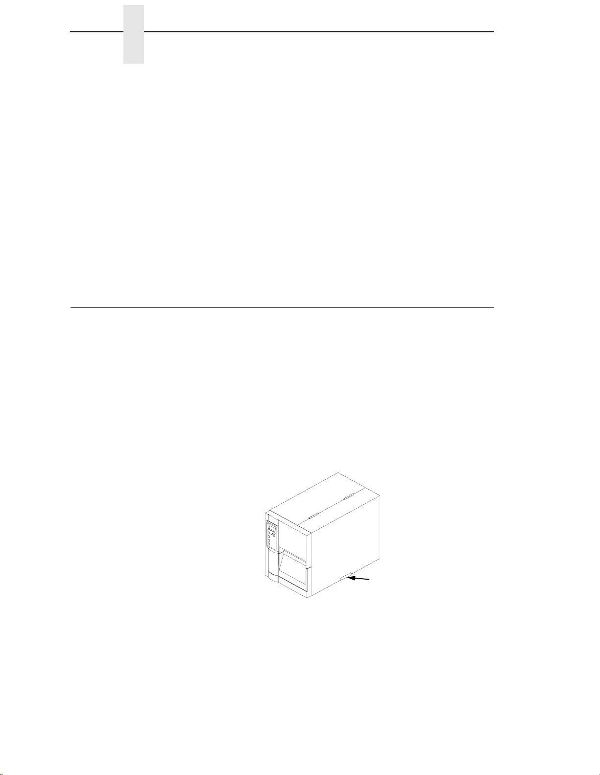
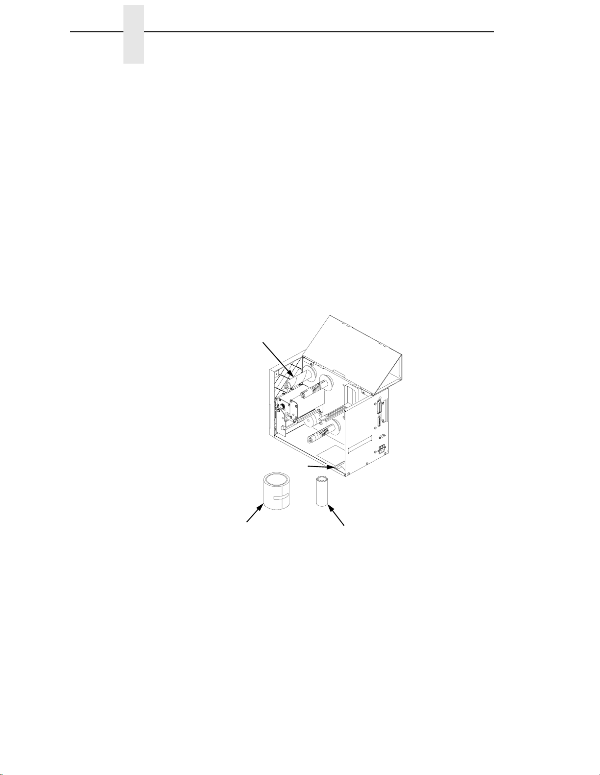
1.
Open the top (and right side) cover by lifting the lip on the lower right side
of the cover.
1
18
Legend:
1) Lip on lower right side of cover
2. Remove the tape securing the label rewind clip to the label rewind
spindle.
3. Place the Media Roll Guide in the down position.
Page 19
4. Remove the sample roll of Printronix ribbon and media from the support
assembly and set them to one side.
1
3
Legend:
1) Tape securing label rewind clip
2) Media Roll Guide
3) Ribbon and Media Sample Rolls
2
19
Page 20
Chapter 1 Unpacking The Printer
Check List
Your T4204 kit contains the items listed below.
• The T4204 printer.
• AC Powercord (not illustrated)
• Programmer’s Manual Order Card (not illustrated).
• Printer User’s Manual (not illustrated).
• Printhead Cleaning Pen (not illustrated)
• Terminating Resistor Packs (not ill ustrated)
• Ribbon Take-Up Core (cardboard) mounted in printer.
• Label Rewind Bracket mounted in printer
• Sample Roll of Printronix Prime Wax Ribbon 4.33” x 164’
• Starter Kit Roll of Printronix 110 Media (100 4.0” x 6.0” labels)
NOTE: If any items are missing, contact your dealer for replacement parts.
1
2
4
Legend:
1) Ribbon Take-Up Core (cardboard)
2) Label Rewind Bracket in stored position
3) Sample Roll of Prime Wax Ribbon
4) Sample Roll of 110 Media
3
20
Page 21

Printer Installation
The following sections will guide you through the installation of the T4204.
WARNING
W A RNUNG
AVISO
AVERTISSEMENT
AVVERTENZA
The printer should never be operated in a location where the operator
and printer can get wet. Personal injury could result.
Der Drucker sollte grundsätzlich nicht an einem Ort aufgestellt und
betrieben werden, an denen der Benutzer oder der Drucker naß werden
könnten, da dies zu Schäden führen könnte.
La impresora nunca deberá utilizarse en un lugar en el que el operador y
la impresora puedan sufrir los efectos de la humedad. De lo contrario,
podrían producirse daños a personas.
Ne faites jamais fonctionner l'imprimante dans un endroit où l'opérateur
et l'imprimante peuvent être mouillés. Il y a risque de préjudice
physique.
Onde evitare il rischio di lesioni personali, non utilizzare mai la
stampante in luoghi in cui l'operatore e la stampante possano venire a
contatto con liquidi.
1. Place the printer in a suitable location that allows easy access to all sides
of the printer. The printer should never be operated while resting on its
side or upside down.
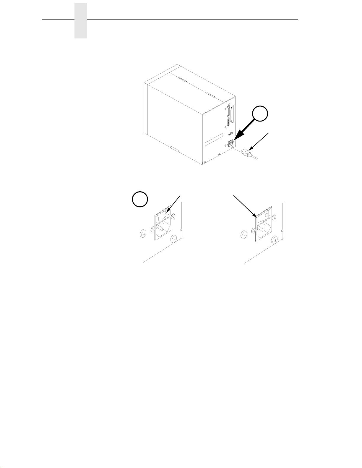
2. Check that the printer power switch is in the OFF (0) position.
3. Attach the AC power cord to the AC power receptacle in the rear of the
printer.
21
Page 22
Chapter 1 Printer Installation
$
1
WARNING
W ARNUNG
AVISO
2
3
$
Legend:
1) AC Power Cord
2) Power Switch Off (0) Position
3) Power Switch On (l) Position
Verify the required voltage on the printer’s model number label on the
rear of the printer.
Überprüfen Sie die erforderliche Spannung an dem Modellschild auf der
Druckerrückseite.
Compruebe el voltaje requerido que figura en la etiqueta del número de
modelo de la impresora que figura en su parte posterior.
AVERTISSEMENT
AVVERTENZA
22
Vérifiez la tension requise sur l'étiquette du numéro de série de
l'imprimante, qui est accolée sur la partie arrière de l'imprimante.
Verificare la tensione richiesta sulla targhetta del numero di serie posta
sul retro della stampante.
4. Attach the AC power cord to a grounded (three prong) electrical outlet of
the proper voltage.
Page 23
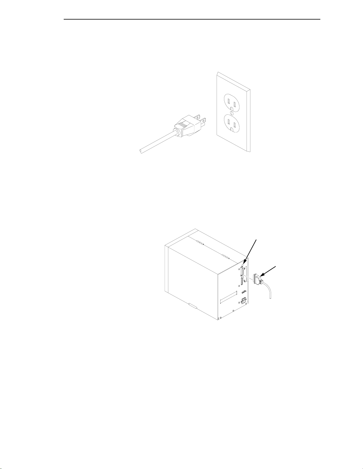
5. Attach The Interface Cable
a. Parallel Interface
Attach a suitable parallel printer cable from the computer to the
Centronics interface connector at the back of the printer. Snap the
bail locks to the Centronics connector to secure the interface cable to
the printer.
Legend:
1) Centronics parallel interface cable
2) Bail lock
1
2
23
Page 24
Chapter 1 Printer Installation
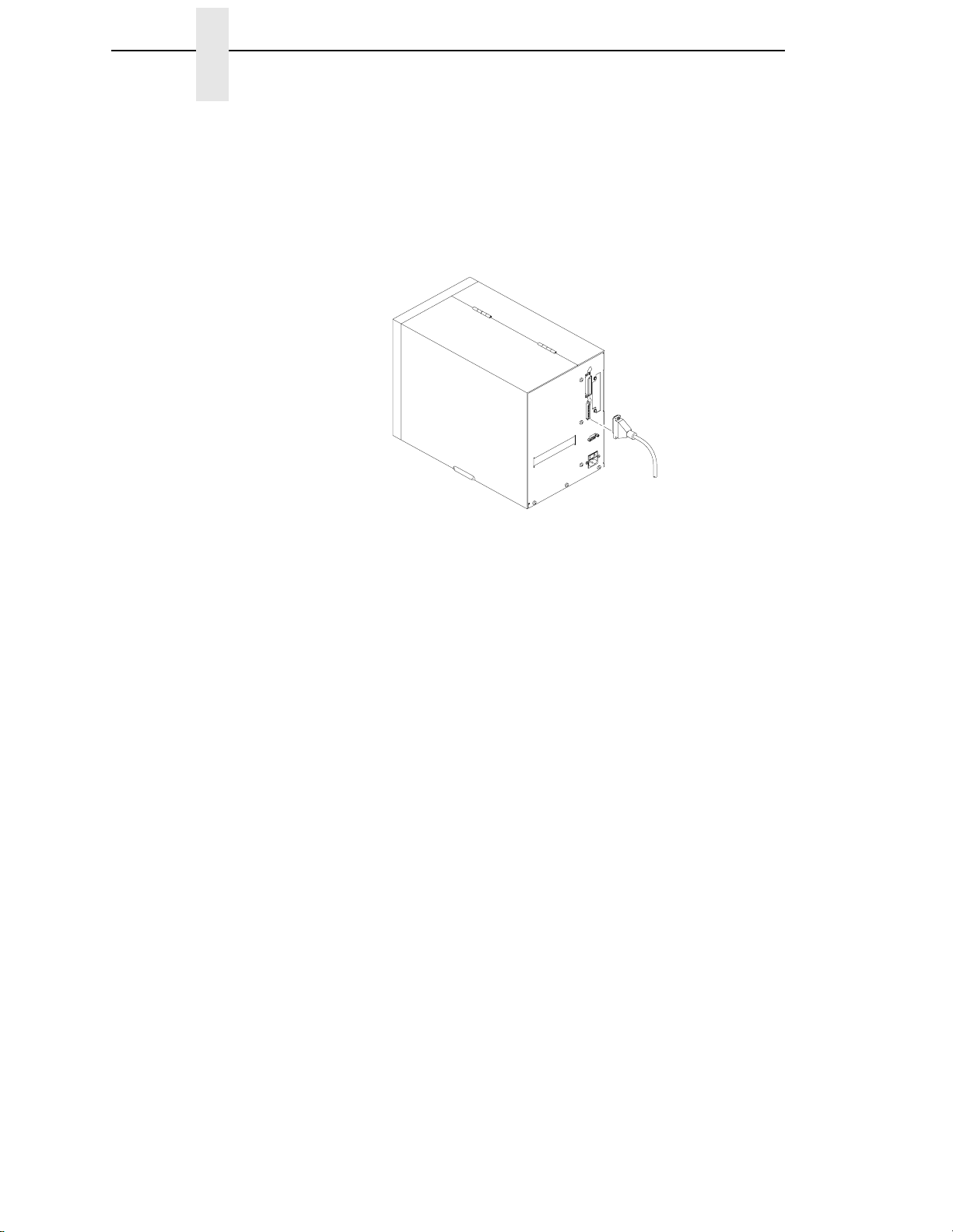
b. Serial Interface
Attach a suitable serial printer cable from the computer to the DB-25
RS-232 Serial interface connector at the back of the printer. For
additional information on serial cable wiring, refer to Chapter 4, page
185.
NOTE: The printer supports simultaneous connection of the Parallel and
Serial interfaces using the Auto Switching feature. See Auto
Switching described on page 78.
24
Page 25
2 Operation
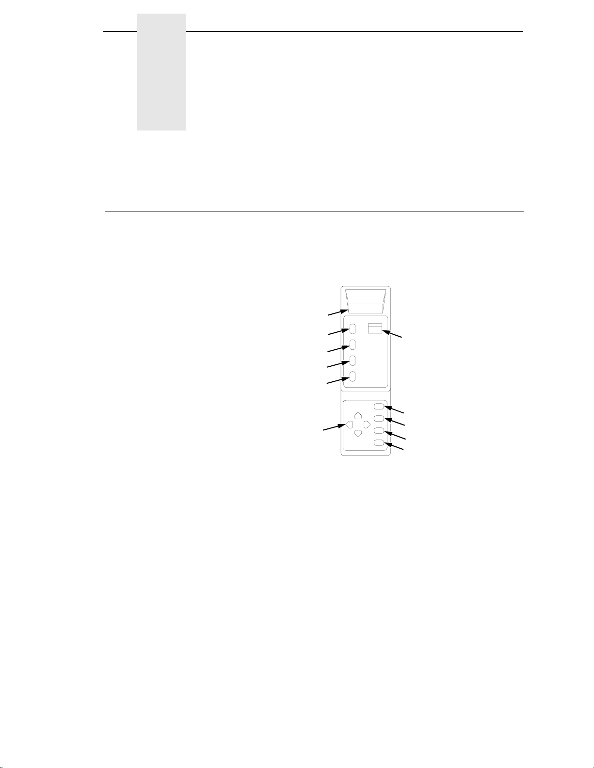
Controls & Indicators
All of the T4204 printer controls and indicators, except for the power switch,
are located on the front panel of the printer, on either the Primary Control
Panel (upper keys), or the Secondary Control Panel (lower keys).
1
11
10
9
8
7
Legend:
1) LCD (Liquid Crystal Display)
2) ONLINE Status Indicator
3) CLEAR Key
4) PRT CONFIG Key
5) JOB SELECT Key
6) ENTER Key
7) Directional “Arrow” keys (4)
8) TEST Key
9) CANCEL Key
10) FEED Key
11) PAUSE Key
2
3
4
5
6
The Primary Control Panel is located at the top left of the printer, on the front
panel. It is accessible with the printer front door either opened or closed. The
panel has a back-lighted Liquid-Crystal Display (LCD), ONLINE status
indicator, and PAUSE, FEED, CANCEL, and TEST keys.
25
Page 26
Chapter 2 The POWER Switch
The Secondary Control Panel is behind the front door assembly below the
Primary Control Panel. It consists of UP, DOWN, PREV, and NEXT arrow
keys to navigate through the printer configuration menus, and CLEAR, PRT
CONFIG, JOB SELECT, and ENTER keys for performing specific functions in
the offline mode or within the printer configuration menu.
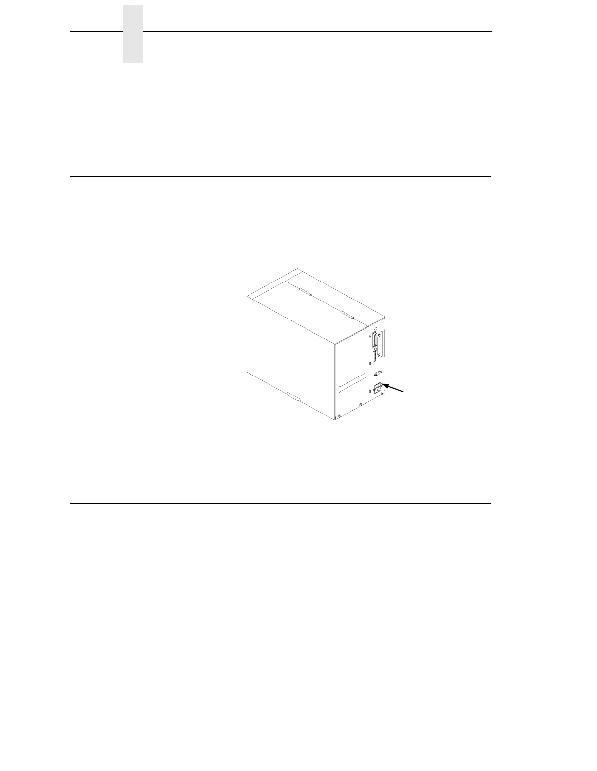
The POWER Switch
The POWER SWITCH is located on the back panel of the printer, in the
bottom left corner. Placing this switch in the ON (1) position applies power to
the printer. An illuminated LCD Message Display indicates the printer power is
ON.
Legend:
1) Printer Power Switch
Powering On The Printer
When you power on the printer, the T4204 executes a self-test. The default
power-up state is online. Once the printer has successfully initialized, the
ONLINE status indicator light will go on, and the LCD indicates the
communication interface selected and the type of emulation installed. The
interface is indicated by PARL for parallel and SERL for serial.
If there is a fault during the self-test, the ONLINE status indicator flashes, and
a fault message appears on the display. The alarm may also sound, if it is
configured to do so.
1
26
Page 27

Operating Modes
Online - In online mode, the printer can receive and print data sent from the
host. Pressing the PAUSE key toggles the printer between the online and
offline mode. The ONLINE status indicator is lit in online mode.
Offline - In offline mode, you may perform operator functions, such as loading
media, or navigating through the printer configuration menu to make changes
or verify option settings. Pressing the PAUSE key toggles the printer from
offline to online mode. The ONLINE status indicator is not illuminated in offline
mode.
Fault - In fault mode, a fault condition exists that must be cleared before
printing can continue. The ONLINE status indicator flashes, the alarm beeps
(if configured to do so) and a descriptive fault message displays.
The current operating mode can be selected through the control panel keys,
or may result from routine operations such as powering on the printer.
Primary Control Panel Keys
PAUSE - Toggles the printer between online [twinax only] and offline modes.
FEED - Advances the media one forms length (active in online or offline
modes).
CANCEL - Cancels all data in the printer (active in online or offline modes).
This key is set to disable from the factory. CANCEL can be enabled in the
MAINT/MISC menu.
TEST - Selects the self-test menu (offline mode only). Pressing the ENTER
key with a Diagnostic Test displayed initiates the test. Pressing the ENTER
key again terminates the test. Press FEED to advance media and clear test
data from the print buffer before returning the printer to the online mode.
Secondary Control Panel Keys
CLEAR - If a fault condition exists, pressing the CLEAR key clears the fault
message and returns the printer to offline mode.
NOTE: If the fault condition has not been corrected before pressing CLEAR,
the fault message appears again when attempting to place the printer
to online status.
PRT CONFIG - Prints the current printer configuration menu settings.
JOB SELECT - Selects a specific printer configuration menu (offline mode
only).
ENTER - Selects the current value within the printer configuration menu
(offline mode only) and displays an asterisk (*) next to the value. If the ENTER
key is locked, the value will not be selected and an “ENTER SWITCH
LOCKED” message displays for one second, followed by a display of the
previously selected value. Pressing the UP and DOWN keys at the same time
unlocks the ENTER key and permits value selection.
27
Page 28

Chapter 2 Loading Media
5) - Navigates the printer menu one level up (offline mode only).
UP (
DOWN (
PREV (
menu (offline mode only).
NEXT (
menu (offline mode only).
UP+DOWN (
the printer menu (offline mode only).
NEXT+PREV (
soft reset (offline only).
Loading Media
The term “media” as used in this manual refers to all the different kinds of
paper, label, or tag stock material that can be printed on by the printer.
Your T4204 can print on continuous paper, adhesive backed labels or nonadhesive tags packaged in roll or fanfold form.
See Appendix B for a list of supplies available from Printronix.
CAUTION
DO NOT TOUCH the Printhead or the electronic components under the
Printhead Assembly. The discharge of electrostatic energy that
accumulates on the surface of the human body or other surfaces can
damage or destroy the printhead or electronic components used in this
device.
6) - Navigates the printer menu one level down (offline mode only).
3) - Navigates between options on the current level of the printer
4) - Navigates between options on the current level of the printer
5+6) - Simultaneously pressing these keys unlocks or locks
4+3) - Simultaneously pressing these keys enables a printer
CAUTION
IMPORTANT
Adhesive backed labels that DO NOT lay flat on the backing liner may
jam the printer. This can cause the label to peel off the liner. The
exposed edges may stick to the label guides and rollers inside the
printer. Genuine Printronix Supplies can be ordered from the Printronix
Distributor where you purchased this printer. Please refer to Appendix B
for sizes and part numbers.
If you run out of labels while printing, do not turn the power switch to
the OFF position while reloading labels. Lost data may result. Prior to
printing labels, it is also recommended you enable the Error Recovery
sub-menu of the PRINTER CONTROL menu, and save it as the power-on
default. Error Recovery forces t he printer to automatical ly reprin t a label
that may have been partially printed prior to the LOAD PAPER fault
message, after additional labels are properly loaded.
28
Page 29
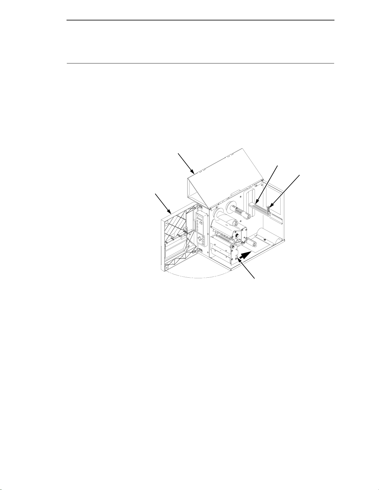
Loading Roll Media
1. Open the top (and right side) cover.
2. Open the front door.
3. Slide the media roll guide down to the end of the media support
assembly.
4. Open the printhead assembly by pushing the release lever towards the
back of the printer. The Printhead assembly will swing upwards.
1
5
4
2
Legend:
1) Top Cover
2) Front Door
3) Printhead Assembly Release Lever
4) Media Roll Guide
5) Media Support Assembly
3
29
Page 30
Chapter 2 Loading Roll Media
5. Slide the media width adjustment tab to the outside stop of the media
sensor assembly and rotate the tab up.
1
Legend:
1) Media Width Adjustment Tab
30
Page 31

6. Slide a roll of media over the media roll guide and onto the support
assembly. Media feeds from the top of the roll and towards the front of the
printer. Push the roll to the back of the support and slide the roll guide
against the outer edge of the media.
7. Thread the label stock through the label sensor assembly and then
between the platen (drive roller) and the printhead. You can also refer to
the Loading A New Roll or Ribbon illustration label on the inside rear
panel of the printer.
1
2
Legend:
1) Roll Guide
2) Media Roll
8. Rotate the media width adjustment tab down and slide it inward until it is
flush with the media. Check the location of the media sensor, and refer to
Sensor Assembly Horizontal Adjustment on page 47.
1
Legend:
1) Media Width Adjustment Tab
31
Page 32

Chapter 2 Loading Roll Media
9. Close the printhead by pressing down on both sides of the fron t of the
printhead assembly.
10. Adjust the media pressure control knob to match the width of the label
stock in use.
Media Wi dth
Pressure Control
2 inches or Less 2 inches
Greater Than 2 inches 4 inches
Knob Settings
CAUTION
32
2
1
Legend:
1) Printhead Assembly
2) Media Pressure Control Knob
Ensure the printhead is down and latched before attempting to print.
Failure to do so may cause a premature failure of the printhead.
Page 33

11. Press the FEED key once to verify that the media advances.
Verify that Print Mode in the Printer Configuration Menu is set for the
media type installed (Direct or Transfer). If Thermal Transfer media is
installed, see “Loading Ribbon” on page 38. The Print Mode submenu is
located in the PRINTER CONTROL Main Configuration menu. See
“Printer Control Menu” on page 91 for more information. Close the
printer’s front door and top (and side) cover if the rewind or thermal
transfer options are not needed.
12.
Press the PAUSE key to place the printer online.
The printer is now ready for printing.
IMPORTANT
The printer will not automatically detect a fault condition when the
printhead is open. When using Transmissive or Reflective media, if the
printhead assembly is opened and media is moved, repositioned, or
replaced, you must press the FEED key after the printhead is locked for
media to advance to the Top-of-Form position.
33
Page 34

Chapter 2 Loading Fanfold Media
Loading Fanfold Media
1. Open the top (and right side) cover on the printer and the front door.
2. Remove the roll media from the media support assembly, if installed.
3. Place the fanfold media behind the printer and insert the first few labels
through the rear panel opening.
4. Open the printhead assembly by pushing the release lever towards the
back of the printer. The Printhead assembly will swing upward.
Legend:
1) Printhead Assembly Release Lever
1
34
Page 35

5. Slide the media width adjustment tab to the outside stop of the media
sensor assembly and rotate the tab up.
1
Legend:
1) Media Width Adjustment Tab
6. Thread the media through the media sensor assembly and then between
the platen (drive roller) and the printhead.
3
2
1
4
Legend:
1) Media Sensor Assembly
2) Platen
3) Printhead
4) Fanfold Media
35
Page 36

Chapter 2 Loading Fanfold Media
7. Rotate the media width adjustment tab down and slide it over until it is
flush with the fanfold media. Check the location of the media sensor, and
refer to “Sensor Assembly Horizontal Adjustment” on page 47.
1
Legend:
1) Media Width Adjustment Tab
8.
Close the printhead by pressing down on both sides of the front of the
printhead assembly.
9.
Adjust the label pressure control knob to match the width of the label
stock in use.
Label Width
Pressure Control
Knob Settings
2 inches or Less 2 inches
Greater Than 2 inches 4 inches
36
Page 37

1
Legend:
1) Printhead Assembly
2) Label Pressure Control Knob
2
CAUTION
IMPORTANT
Ensure the printhead is down and latched before attempting to print.
Failure to do so may cause a premature failure of the printhead.
10. Press the FEED key once to verify that the labels advance.
Verify that Print Mode in the Printer Configuration Menu is set for the
media type installed (Direct or Transfer). If Thermal Transfer media is
installed, see “Loading Ribbon” on page 38. The Print Mode submenu is
located in the PRINTER CONTROL Main Configuration menu. See
“Printer Control Menu” on page 91 for more information. Close the
printer’s front door and top (and side) cover if the rewind or thermal
transfer options are not needed.
11.
Press the PAUSE key to place the printer online.
The printer is now ready for printing.
The printer will not automatically detect a fault condition when the
printhead is open. When using Transmissive or Reflective media, if the
printhead assembly is opened and media is moved, repositioned, or
replaced, the FEED key must be pressed after the printhead is locked for
media to advance to the Top-of-Form position.
37
Page 38

Chapter 2 Loading Ribbon
Loading Ribbon
Skip this section when using Direct Thermal Media.
1. Slide the appropriate thermal transfer ribbon roll onto the ribbon supply
spindle and open the Printhead assembly by pushing the release lever
towards the back of the printer.
1
Legend:
1) Ribbon Supply Spindle
2) Printhead Assembly Release Lever
2
38
Page 39

2. Thread the transfer ribbon between the label sensor assembly and the
printhead bracket. Continue threading the ribbon between the platen (and
label stock, if loaded) and the printhead.
For easy ribbon threading, slide half of the ribbon between the side of the
label sensor assembly and the printhead bracket. Guide it from the side of
the printer through the ribbon path.
1
2
3
4
Legend:
1) Ribbon Take-up Spindle
2) Ribbon Supply Roll
3) Printhead Bracket
4) Label Sensor Assembly
39
Page 40

Chapter 2 Loading Ribbon
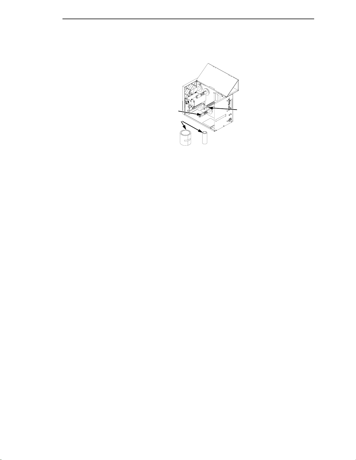
3. Wrap the transfer ribbon from the front of the printhead assembly to the
backside of the ribbon take-up spindle. Attach the ribbon to the take-up
core (fiberboard tube) with tape.
When installing a new roll of Printronix ribbon, fold the ribbon just behind
the adhesive strip and attach the strip to the ribbon take-up core.
Manually rotate the spindle counterclockwise to feed the unusable portion
of the ribbon leader around the take-up spindle.
1
Legend:
1) Label and Ribbon Loading Diagram
4. Close the printhead by pressing down on both sides of the fron t of the
printhead assembly.
5.
Close the printer’s front door and top (and side) cover if the label rewinder
is not needed.
6.
Verify that Print Mode is set for Transfer in the Printer Configuration
Menu. The Print Mode submenu is located in the PRINTER CONTROL
Main Configuration menu. See “Printer Control Menu” on page 91 for
more information.
7.
The printer is now ready for Thermal Transfer Printing.
40
Page 41

Label Rewinding
The printer can be set up to automatically rewind labels into a roll by using the
label rewinder.
1. Remove the front door insert cover from the front door by sliding the insert
cover up to unlock it, then pushing it out of the front of the door assembly.
1
2
Legend:
1) Front Door Insert Cover
2) Label Taken Sensor Gate
2. Remove the label rewinder bracket from inside the printer. Turn the
thumb screw holding the bracket to the printer chassis counter-clockwise
to loosen. The screw is used for mounting and storing the bracket.
2
1
Legend:
1) Label Rewinder Bracket
2) Thumbscrew
41
Page 42

Chapter 2 Label Rewinding
3. Hook the two stepped tabs of the label rewind bracket onto the two
notches on the top edge of the platen roller assembly’s tear-bar plate.
Swing the bracket down. Align the bracket’s tabs with the platen’s bracket
reference holes and insert them.
4.
Secure the bracket with the thumb screw.
5.
Remove the label rewind clip from the label rewinder spindle.
1
2
Legend:
1) Label Rewind Bracket
2) Platen Roller Tear Bar Plate
3) Label Rewinder Spindle
4) Label Rewind Clip
6.
With the label stock already loaded and the front door open (To load
3
4
labels see “Loading Roll Media” on page 29), thread the label stock
around and below the platen roller assembly.
7.
Press the FEED key with the printhead closed, as needed, to supply more
label stock or liner.
1
42
Legend:
1) Label Stock/Liner
Page 43

8. If a label is on the end of the label liner, remove it.
a. Thread the liner around the label rewinder spindle counter-clockwise,
as shown.
b. Slide the label rewind clip over the label liner end and onto the label
rewinder spindle.
c. Fold the label liner over the clip to the back of the printer. This helps
lock in the liner.
d. Press the FEED key until the label liner is taut.
1
2
Legend:
1) Label Rewinder Spindle
2) Label Rewind Clip
9. To rewind labels, set Media Handling to Continuous in the configuration
menu. The Media Handling submenu is located in the PRINTER
CONTROL Main Configuration menu. See Chapter 3 for more information
on configuring the printer.
10.
Close the printer’s front door and top (and side) cover.
43
Page 44

Chapter 2 Label Peel Off
Label Peel Off
The printer can be set to automatically peel off labels from the backing liner
and dispense them one at a time while rewinding the liner. This configuration
requires use of the printer’s label rewinder.
1.
Remove the front door insert cover from the front door of the printer. Slide
the insert cover up to unlock it, then push it out of the front of the door
assembly.
2.
For Peel-Off mode, flip the label taken sensor gate down.
3.
If the label rewinder bracket is mounted on the platen tear bar assembly
at the front of the printer, remove it and secure it in the stored position as
shown.
1
3
2
Legend:
1) Front Door Insert Cover
2) Label Taken Sensor Gate
3) Label Rewind Bracket
4.
With the label stock already loaded and the front door open (To load
labels, see “Loading Roll Media” on page 29) thread the label liner around
and below the platen roller assembly.
44
Page 45

5. Press the FEED key with the printhead closed, as needed, to supply more
label stock or liner.
6. If a label is on the end of the label liner, remove it.
7. Thread the liner around the label rewinder spindle counter-clockwise, as
shown. Slide the label rewind clip over the label liner end and onto the
label rewinder spindle.
1
2
Legend:
1) Label Rewinder Spindle
2) Label Liner
8. Fold the label liner over the clip to the back of the printer. This helps lock
in the liner.
1
Legend:
1) Label Rewind Clip
45
Page 46

Chapter 2 Label Peel Off
9. Press the FEED key until the label liner is taut.
10. For automatic label peel-off mode, set Media Handling to Peel-Off in the
configuration menu. The Media Handling submenu is located in the
PRINTER CONTROL Main Configuration menu. See Chapter 3 for more
information on configuring the printer.
1
Close the printer’s front door and top (and side) cover.
Legend:
1) Peeled Label Area
Peel-Off Mode
11.
Press the PAUSE key to place the printer Online.
12.
Press the FEED key. A label should advance to the peel-off position
under the label taken sensor gate and “LABEL PRESENT Remove Label”
should be displayed.
NOTE: While printing a print job, do not press the FEED key with the ‘LABEL
PRESENT Remove Label’ message displayed or the message will be
removed until the PAUSE key is pressed. Also, each pressing of the
FEED key will cause a blank label to be added at the end of the print
job.
13.
Remove the label. “ONLINE” should then be displayed.
NOTE: A problem where labels drop back down onto the liner before they
can be manually removed can occur, causing the label taken sensor
to falsely sense the label was removed. Labels of 1.0 to 1.5 inches
long are more likely to demonstrate this condition.
This problem can be resolved by decreasing Print Speed or Setting
Paper Feed Shift (under the PRINTER CONTROL menu) from 0.00
inches to a negative (-) 0.07 to 0.10 inch value to retract the label
back slightly keeping it in the horizontal position under the sensor.
46
Page 47

Label V ariations And The Label Sensor
Your T4204 is equipped with a transmissive sensor that detects the gap
between labels while they are being printed. The trailing edge of the gap
establishes the Top-of-Form position. This feature depends on the ability of
the sensor to “see through” the label liner, index hole or notch in the media. In
order to support this type of media, select the Transmissive option under the
PRINTER CONTROL Media Sensor menu. The Transmission Media Sensor
Assembly must be partitioned correctly. (See Sensor Assembly Horizontal
Adjustment, below.)
A reflective sensor located on the lower portion of the same sensor assembly
detects a black horizontal stripe on media with reflective label backing. The
trailing edge of the black stripe establishes the Top-of-Form position. This
feature depends on the ability of the sensor to detect the difference in the
amount of light reflected off the back of the label material and the black stripe.
Select the Reflective option under the PRINTER CONTROL Media Sensor
menu in order to support this type of media. Additionally, the Reflector Sensor
must be in the correct horizontal position.
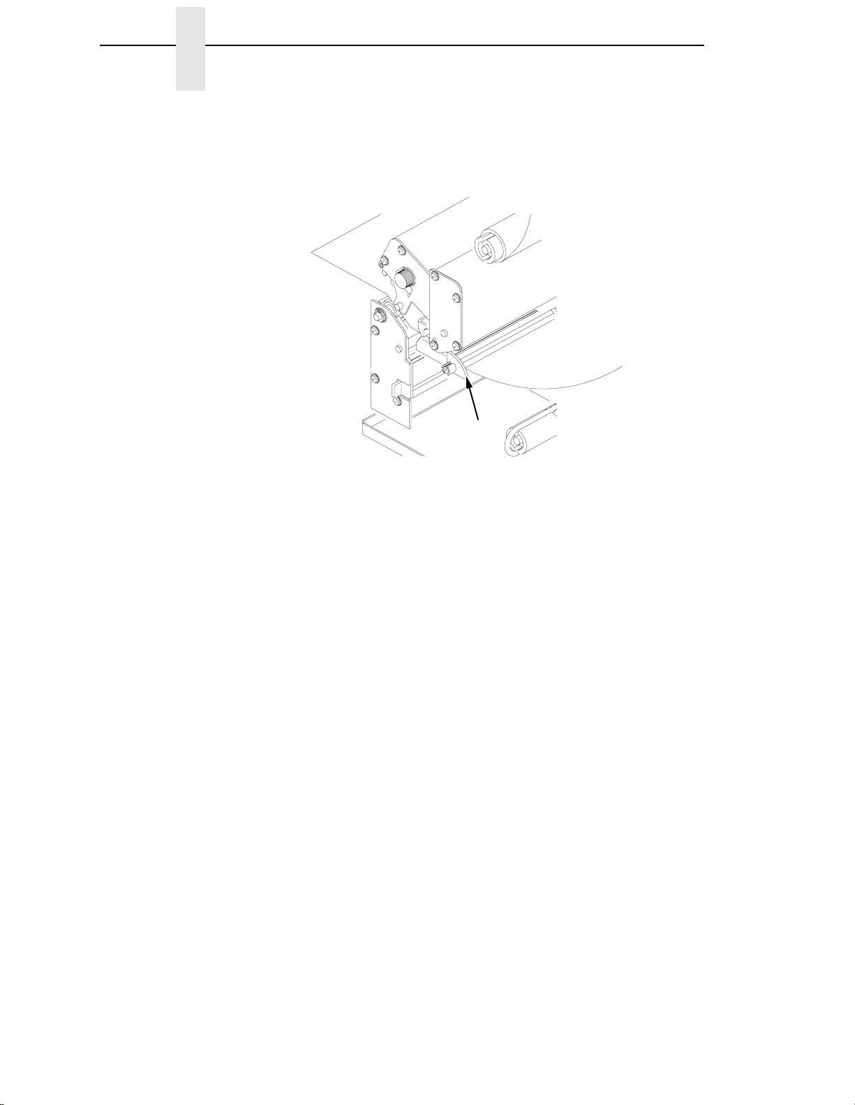
Sensor Assembly Horizontal Adjustment
In order to accurately detect the gap, hole, notch, or narrow black stripe, the
transmissive sensor assembly can be moved 1.4 inches along the width of the
media by squeezing together the two blue locking tabs, located under the
label guide, and sliding the sensor to the desired position. The actual location
of the transmissive sensor is indicated by the sensor crystal visible at the front
of the label guide when the printhead assembly is open.
Position the transmissive sensor directly under the hole or notch. If it extends
the full width of the media, position it in the middle of the transmission liner
gap.
The reflective sensor is located directly below R2, the resistor farthest to the
right on the sensor PCBA. The resistor is visible when the printhead is open.
The reflective sensor should be positioned as close as possible in the middle
of the width of the label black stripe.
When you use either Transmissive or Reflective Media sensing, adhere to the
media specifications described in Appendix A and ensure that the Page
Length value set in the PRINTER CONTROL Main Menu of the Configuration
Menu (or Page Length value sent via software command) matches the
physical length of the label or tag stock installed in the printer. In addition, do
the sensor calibration procedure described below whenever a different type of
media sensing will be required (Transmissive or Reflective), when installing
untried media, or when the printer is losing Top-of-Form position. Loss of Topof-Form is usually followed by an error message on the LCD, such as “GAP
NOT DETECTED Check Media” or “LOAD PAPER”.
47
Page 48

Chapter 2 Calibrating The Transmissive And Reflective Sensors
Calibrating The T ransmissive And Reflective Sensors
Due to manufacturing differences in transmissive and reflective label stock,
the sensors may have difficulty distinguishing between the label and the liner
(gap) or the label and the black mark. When this occurs, the printer will
display an error message on the LCD such as “GAP NOT DETECTED Check
Media” or “LOAD PAPER”. The printer’s sensitivity for detecting the TOF
(Top-Of-Form) position of the media installed can be optimized by using the
Calibrate features in the PRINTER CONTROL menu.
Sensor sensitivity can be improved by changing the Refl Value for reflective
media or by changing the Trans Value for transmissive media. These values
can be changed manually within the PRINTER CONTROL menu or can be
determined automatically by using the Run Calibrate procedure. The change
in values (derived automatically or manually) takes effect immediately within
the current configuration menu, but is not automatically saved. If Run
Calibrate is performed again the new values will overwrite the previous values
for the current menu.
The new values can be saved into non-volatile memory (menus 1-8 only) by
using the Save Configuration procedure. If the current menu in use is the
Factory menu, the values will take effect but cannot be saved into memory
and will be lost when the printer is powered off.
Use the Run Calibrate procedure to automatically determine the Trans or Refl
Values before attempting to change the values manually. When Run Calibrate
has completed successfully, the Sensed Distance option in the Calibrate
menu will display a distance in inches based on the media type in use:
• transmissive media = the label length plus one gap length
• reflective media = the distance from the trailing edge of one black
stripe to the trailing edge of the next black stripe.
The Sensed Distance value cannot be manually changed and is updated only
as a result of the Run Calibrate procedure. The factory default value of
Sensed Distance is 0.00 inches.
If Run Calibrate fails to determine the proper values and ends with a fault
message displayed (GAP NOT DETECTED or LOAD PAPER), you can try it
again by going back to Run Calibrate under the PRINTER CONTROL main
menu and then press the ENTER key. Or, you can manually change the
Trans Value or the Refl Value. Trans Value and Refl Value have a range of 0
- 20 (factory default = 10).
Once the correct values are determined and the Page Length setting in the
PRINTER CONTROL menu is equal to (or slightly less) than the physical
page length, depress the FEED key to advance media and determine if it
consistently stops at the correct TOF position each time.
48
Page 49

Run Calibrate Procedure
NOTE: Verify that the media installed in the printer matches the PRINTER
CONTROL menu Media Sensor option (Transmissive or Reflective).
Verify that the transmissive sensor is horizontally positioned to permit
sensing of the notch, gap, or black stripe. (See “Sensor Assembly
Horizontal Adjustment” on page 47.)
1.
Press and release the PAUSE key to place the printer offline.
2.
Open the printer front door to allow access to the Secondary Control
Panel.
3.
Press and release the UP and DOWN (
unlock the printer menu. “ENTER SWITCH UNLOCKED” appears on the
LCD.
4.
Press the NEXT (
LCD.
5 and 6) keys simultaneously to
4) key until “PRINTER CONTROL” appears on the
5.
Press the DOWN (
6.
Press the NEXT (
7.
Press the DOWN (
8.
Press the ENTER key. The media will advance a minimum of 11 inches
plus the distance required to detect three additional Top-of-Form
positions.
The procedure is completed successfully if no fault is displayed and the
Sensed Distance value is correct. See “Sensed Distance” on page 95 for
a detailed description of Sensed Distance.
NOTE: If a fault message such as “GAP NOT DETECTED” or “LOAD
PAPER” appears while performing the Run Calibrate procedure,
press the CLEAR key and perform the Run Calibrate procedure
again, by going back to Run Calibrate under the PRINTER
CONTROL main menu and then press the ENTER key.
9.
Press the UP (
the LCD.
10.
Press the FEED key. The media should advance one forms length.
NOTE: If the Page Length value is longer than the physical page length of the
media in use, the printer will continue to advance media to achieve
that Page Length value and then stop at the next TOF position.
11. Press the PAUSE key to place the printer Online.
6) key. “Page Width” appears on the LCD.
4) key until “Calibrate” appears.
6) key. “Run Calibrate” appears.
5) key until “OFFLINE PRINTER CONTROL” appears on
49
Page 50

Chapter 2 Cleaning The Printhead
NOTE: The amount of media advancement is also based on which Media
Handling selection is enabled under the PRINTER CONTROL Main
menu of the Configuration Menu. ‘Tear-Off’ and ‘Tear-Off Strip’ (after
Tear-Strip Time) will advance the media until the Top-of-Form of the
next form is positioned over the Tear bar. When ‘Continuous’ Media
Handling is selected the media will advance only until the Top-ofForm of the next form is positioned under the printhead.
12.
Press the PAUSE key to place the printer Online.
Cleaning The Printhead
One cause of poor print quality is a dirty printhead. You should clean the
printhead whenever you replace the ribbon (thermal transfer mode) or install
new media (direct thermal mode).Clean the printhead with the printhead
Cleaning Pen supplied with the printer, or with Isopropyl alcohol and a cotton
swab.
1.
Open the printhead assembly.
2.
Pull back any rolled or fanfold media located directly under the printhead.
1
Legend:
1) Printhead Assembly
50
3. Gently rub the felt tip of the Cleaning Pen or a cotton swab with Isopropyl
alcohol across the amber area of the printhead.
4. Allow the printhead to dry for one minute before reloading the labels.
Page 51

3 Configuring The Printer
Overview
Changing printer settings, such as print speed or emulation, is referred to as
configuration. The configuration process is done using the secondary control
panel and includes the following:
• Configuring the printer for different host interface options
• Customizing label formats
• Checking printer status
• Running various maintenance tests
NOTE: Control codes sent by the host system will override the control panel
Menu Navigation
settings.
The secondary control panel consists of four function keys and four arrow
keys. Figure 1 shows the keypad section of the panel. An explanation of each
key is in Table 1.
This section explains how to use the secondary control panel to change
individual settings and save them as a customized configuration.
Legend:
1) UP Key
2) PREV Key
3) DOWN Key
4) CLEAR Key
5) PRT CONFIG Key
6) NEXT Key
7) JOB SELECT Key
8) ENTER Key
1
2
3
Figure 1. Secondary Control Panel
4
5
6
7
8
51
Page 52

Chapter 3 Menu Navigation
Table 1: Key Function Summary - Secondary Control Panel
Key Function
CLEAR If a fault condition exists, pressing this key clears the fault message
and returns the printer to offline mode.
NOTE: If the fault condition is not corrected before pressing CLEAR,
the message reappears when attempting to place the printer
online.
PRT CONFIG Prints the current printer configuration menu settings (offline mode
only).
JOB SELECT Selects a specific printer configuration menu (offline mode only).
ENTER Selects the current value within the printer configuration menu (offline
mode only) and displays an asterisk (*) next to the value. If the ENTER
key is locked, the value will not be selected and an “ENTER SWITCH
LOCKED” message displays for one second, followed by a display of
the previously selected value. Pressing the UP and DOWN keys at the
same time unlocks the ENTER key and permits value selection.
UP (
5)
DOWN (
PREV (
NEXT (
UP+DOWN
(
5+6)
NEXT+PREV
(
4+3)
6)
3)
4)
This key causes the printer to go up one level in the menu structure
(offline mode only).
This key causes the printer to go down one level in the menu structure
(offline mode only).
If the menu selection is a value, pressing this key causes the value to
be decremented. If the menu selection is an option, pressing this key
allows selection among options on the current menu level. Holding the
key down causes the key to repeat at about seven times a second
(offline mode only).
If the menu selection is a value, pressing this key causes the value to
be incremented. If the menu selection is an option, pressing this key
allows selection among options on the current menu level. Holding the
key down causes the key to repeat at about seven times a second
(offline mode only).
Simultaneously pressing these keys unlocks or locks the printer menu
(offline mode only). This is the default key combination for locking/
unlocking the secondary control panel. You can change the key
combination. See page 72.
Simultaneously pressing these keys enables a printer soft reset (offline
mode only).
52
Page 53

Using The Secondary Control Panel
Using The Secondary Cont rol Panel
Configuration parameters are set from the secondary control panel or are
retrieved from the printer’s memory. The parameters define how the printer
will respond to command and interface signals from the host computer.
The configuration menu structure consists of the main configuration menus
and the corresponding submenus, where applicable.
NOTE: Many of the selectable configurations refer to printer options or
features that may or may not be present in your printer. Selecting an
option or feature that is not present will result in no action being
performed by the printer, or an ‘OPTION NOT INSTALLED’ message
displayed.
Moving Within The Configuration Menu
To configure the printer, it must be offline. If the ONLINE indicator is lit, press
and release the PAUSE key to place the printer offline. When the printer is
offline, OFFLINE appears on the top line of the LCD and CONFIG. CONTROL
appears on the next line.
Figure 2 shows the configuration main menu options. For details on the
parameters that pertain to those options, refer to the specified pages.
Movement within the configuration menus is controlled by using the
appropriate arrow keys. (See Table 1, for more details on the function of the
operator panel keys.)
Figure 3 shows how to change a configuration menu option and the
messages that appear in the display after you press each key.
If you follow the example shown in Figure 3, you will configure the printer for
Direct Thermal Print Mode.
In this manual the factory default settings for all available options are
indicated by an asterisk (*) located to the right of the option.
You can select different options and save them as the power on default;
however, they can only be saved to configurations menus 1-8. Changes made
to the factory configuration menu cannot be saved.
When the printer is online, the first line of the LCD indicates ONLINE and the
second line lists the active interface port and type of emulation.
53
Page 54

Chapter 3 Menu Navigation
OFFLINE
CONFIG.
CONTROL
page 65
Load Config.
Save Config.
Print Config.
Delete Config.
Power-Up Config.
Protect Configs
Name Configs.
Reset Cfg Names
ETHERNET
PARAMS
IP Address
Gateway Address
Subnet Mask
MAC Address
Novell Protocol
NetBIOS Protocol
Novell Frame
PPM Port Number
PPM Port Timeout
1
page 90
ACTIVE IGP
EMUL
page 67
IGP/PGL
IGP/VGL
PRINTER
CONTROL
page 91
Page Width
Page Length
Print Speed
Print Intensity
Print Mode
Media Sensor
Media Handling
Paper Feed Shift
Hor Image Shift
Ver Image Shift
Calibrate
Tear-Strip Time
Clip Page
Error Recover
EMULATION
page 68
LinePrinter+
IGP/PGL
IGP/VGL
1
CTHI
FONT
MEMORY
page 97
Max Char Memory
Max Cache Memory
Max Cache Size
Max Cached Char
Max Fonts Loaded
Font Weight
Installed Fonts
MAINT/MISC
page 69
Alarm
Power-Up State
Hex Dump Mode
Ptx Setup Opti on
Display Language
Downloaded Fonts
File System
Cancel Key
Auto Locking
Set Lock Key
Auto Label Map
Compatibility
Power Saver Time
DIAGNOSTICS
page 100
Printer Tests
System Memory
Print Statistics
HOST
INTERFACE
page 77
1
Twinax
1
Coax
Auto Switching
Centronics*
Serial
IEEE 1284
Ethernet
1
if installed
1
54
Figure 2. Configuration Main Menu
Page 55

Selecting A Menu Option
Step Press LCD Notes
1. OFFLINE
2. ENTER SWITCH
3. OFFLINE
4. PRINTER CONTROL
5. PRINTER CONTROL
6. Print Mode
7. Print Mode
8. Print Mode
PAUSE
+
OR
OR
ENTER
UNTIL
CONFIG. CONTROL
UNLOCKED
PRINTER CONTROL
Page Width
Print Mode
Transfer*
Direct
Direct*
Allows you to make
configuration changes.
Cycle through the
choices.
Figure 3. Moving within the Configuration Menu
Selecting A Menu Option
By default, the ENTER key is “locked” when the printer is turned on. This
prevents accidental changes to the configuration menu. If you press the
ENTER key when the key is locked, the message “ENTER SWITCH
LOCKED” is displayed on the LCD for one second, and the value will not be
selected.
To unlock the ENTER key, press the UP and DOWN arrow keys
simultaneously. This toggles the enter lock function.
If this function is performed while the ENTER key is locked, the message
“ENTER SWITCH UNLOCKED” will be displayed for one second, and the
ENTER key will be unlocked.
If this function is performed while the ENTER key is unlocked, the message
“ENTER SWITCH LOCKED” will be displayed for one second, and the
ENTER key will be locked.
When the ENTER key is pressed (with the ENTER key unlocked), the value
displayed is entered and the configuration is changed immediately.
55
Page 56

Chapter 3 Menu Navigation
NOTE: The lock and unlock function can be configured to be other than the
UP and DOWN keys. (See “Set Lock Key” on page 72.)
IMPORTANT
This change takes effect for all subsequent data and operations for the
printer only after the printer is placed in the Online mode. The
configuration change(s) stay in effect only while the printer is powered
on. When the power is turned off, all current configuration data are lost
unless you save the configuration.
To save configuration information permanently or to select it as the power-up
default, see page 57.
Changing Printer Set tings
1.
Make sure the printer is offline. If the ONLINE indicator is lit, press the
PAUSE key. The following message will display:
OFFLINE
CONFIG CONTROL
2.
3.
3or 4 key for the following display.
Press
OFFLINE
PRINTER CONTROL
Press the
6 key for the following display:
PRINTER CONTROL
Page Width
4.
3or 4 to cycle through these options:
Press
Page Width
Page Length
Print Speed
Print Intensity
Print Mode
Media Sensor
Media Handling
Paper Feed Shift
Hor Image Shift
Ver Image Shift
Calibrate
Tear-Strip Time
Clip Page
Error Recover
56
Page 57

Saving A Configuration
5. When the desired menu displays, press the6 key to access the available
options or submenus.
IMPORTANT
IMPORTANT
6. Press the
7. Press the ENTER key to select a value. An asterisk (*) displays next to
the selected value.
8. If there are more values you want to change, use the
RIGHT, UP, or DOWN) keys to access the value and the ENTER key to
select it. At any time, you may press the
one level higher.
9. At any time, you may press the PAUSE key to exit the configuration menu
and place the printer online. Once you have finished selecting all your
options, save your configuration.
The printer must be placed in the Online mode before the new menu
selections or changes take effect.
If you do not save your configuration, all your new values will be lost
when you turn off the printer.
3or 4 key and hold to scroll through the values.
3456 (LEFT,
5 key to return to the options
Saving A Configuration
You can save up to eight different configurations to meet eight unique print job
requirements. For example:
Factory: Factory Default (This cannot be altered.)
Config. 1: Selects RS-232 Serial Interface
Selects Page Width of 4 inches
Selects Page Length of 24 inches
Selects image Horizontal Shift of 0.20 inches, etc.
Config. 2: Selects Parallel Interface
Selects Page Width of 2.2 inches
Selects Page Length of 25.0 mm
Selects image Vertical Shift of 0.10 inches, etc.
The configurations are saved and stored in non-volatile memory for later use.
These configurations, including the factory default configuration, will not be
erased from memory when the printer power is turned off.
If you do not save your configuration (to the non-volatile memory) before you
turn off the printer, any changes made to that current configuration will be lost.
NOTE: If the Protect Configs. option is enabled, the new configuration will not
be saved unless the existing configuration has been deleted.
57
Page 58
Chapter 3 Menu Navigation
Follow these steps to save a new configuration:
1. Press the PAUSE key to take the printer offline. The following message
displays:
OFFLINE
CONFIG. CONTROL
2. Press the
CONFIG CONTROL
Load Config.
3. Press the
CONFIG CONTROL
Save Config.
4. Press the
Save Config.
1*
5. Press the
factory default configuration is not listed.
6. When the desired number displays, press ENTER to select it. The
following message displays briefly:
Saving
Configuration
6 key until:
3 or 4 key until the following displays:
6 key until:
3 or 4 key to cycle through the options (1-8). Note that the
58
When processing is completed, the display shows:
Save Config.
X
*
NOTE: If the configuration number has been previously saved and the
Protect Configs. option is enabled under CONFIG CONTROL, the
following error message displays:
CONFIG. EXISTS
Delete First
If the above occurs, see page 59, step 4.
It is recommended that you print your configuration and store it in a safe place
for future reference. Refer to page 60.
Page 59

Modifying A Saved Configuration
Modifying A Saved Configu rat ion
You can change a saved configuration by rewriting over it. For example, you
can modify Config. 1, shown below. Suppose you want to keep all the settings
but you want to select the parallel interface instead of the serial interface.
Config. 1: Selects RS-232 Serial Interface
Selects Page Width of 4 inches
Selects Page Length of 24 inches
Selects Image Horizontal Shift of 0.20 inches, etc.
1. Load the configuration to be changed (for example, Config. 1).
a. Press the PAUSE key to take the printer offline.
OFFLINE
CONFIG. CONTROL
b. Press the
CONFIG. CONTROL
Load Config.
c. Press the6 key.
Load Config.
1*
d. Press the
e. When the desired number displays, press the ENTER key to select it.
The following message is displayed while loading.
Loading Saved
Configuration
Then, the following message displays when it is loaded:
Load Config.
X
*
2. Move through the menu and change all the desired values. (In this
example, under Host Interface, you would change the value from Serial to
Centronics.)
6 key.
3 or 4 key to cycle through the options: Factory 1-8.
3. Press the ENTER key to save each new value. An asterisk (*) displays.
4. Before saving the modified configuration, you must delete the original
configuration if the Protect Configs . opti on is enable d.
a. Press the
5 key.
59
Page 60

Chapter 3 Menu Navigation
b. Press the
CONFIG. CONTROL
Delete Config.
c. Press the
d. Press the
desired number displays, press the ENTER key to select it. The
following message is displayed.
Deleting
Configuration
Then, the following displays when it is deleted:
Delete Config.
X
*
5. Save the new configuration as described in the page 57. Make sure you
select the same number (e.g., Config. 1) when saving the modified
configuration. The new configuration writes over the existing one.
3or 4 key until the following displays:
6 key.
3or 4 key to cycle through the options (1-8). When the
6. Print a copy of this newest configuration (see below) and store it in a safe
place.
Printing A Configuration
Print and store your configurations for future reference. The printout provides
a list of the parameters that were set when you configured the printer. A
sample configuration printout is shown in Figure 4.
To print a configuration:
1. Press the PAUSE key to take the printer offline.
OFFLINE
CONFIG. CONTROL
2. Press the
3. Press the
6 key for the following display:
CONFIG. CONTROL
Load Config.
3 or 4 key until the following displays:
CONFIG. CONTROL
Print Config.
60
4. Press the
6 key.
Page 61

Printing A Configuration
5. Press the3 or 4 key to cycle through the following printout options:
Current*
Factory
Power-Up
All
1-8 customized configurations
6. When the desired option displays, press the ENTER key. The printer
prints the specified configuration. Refer to Figure 4, for a sample
configuration printout.
NOTE: If the configuration you want to print has not been saved, the
following message will display momentarily:
CONFIG. DOES NOT
EXIST/Save Fi rst
This message indicates that no configuration menu has been saved
under the configuration value you have selected and therefore cannot
be printed. You must either select another configuration to print or
load and then save a configuration to that configuration value first.
61
Page 62

Chapter 3 Menu Navigation
62
Figure 4. Sample Configuration Printout (sheet 1 of 3)
Page 63

Printing A Configuration
Figure 4. Sample Configuration Printout (sheet 2 of 3)
63
Page 64

Chapter 3 Menu Navigation
64
Figure 4. Sample Configuration Printout (sheet 3 of 3)
Page 65

Menu Options
The rest of this chapter shows each menu along with its possible choices, and
explains what each of the choices mean.
CONFIG. CONTROL Menu
The CONFIG. CONTROL menu allows you to control your printer’s
configurations according to the specifications necessary for your print jobs.
CONFIG.
CONTROL
(from page 54)
CONFIG. CONTROL Menu
* = Factory Default
Load Config.
Factory*
1-8
Name
Configs
1*
(1-8)
Save Config. Print Config.
1*
(1-8)
Reset Cfg
Names
1* (1-8)
All
Current*
Factory
Power-up
All
1-8
Delete Config.
1*
(1-8)
Power-up
Config.
Factory*
1-8
Protect
Configs.
Disable*
Enable
Load Config.
The printer can store up to eight configurations in memory. This parameter
allows you to select and load a specific configuration.
Save Config.
This option allows you to save up to eight unique configurations to meet
different print job requirements. This eliminates the need to change the
parameter settings for each new job. The configurations are stored in
memory, and will not be lost if you turn off the printer. If the Protect Configs.
parameter is enabled, the new configuration will not be saved unless the
existing configuration has been deleted first. The factory default configuration
cannot be changed. See page 57 for details.
65
Page 66

Chapter 3 Menu Options
Print Config.
This option is used to print a listing of various stored printer configurations. It
is recommended you store printouts of your configurations in a safe place for
quick referral.
Delete Config.
You can delete one or all of your eight customized configurations. The factory
default configuration cannot be deleted.
Power-Up Config.
You can specify which of the nine configurations (Factory or 1-8) will be the
power-up configuration.
Protect Configs.
You can specify whether or not a new configuration should overwrite an
existing configuration when you activate the Save Configs. parameter. When
disabled (default), the new configuration will overwrite the existing
configuration. When enabled, the new configuration will
existing configuration, and the message “CONFIG. EXISTS / Delete First”
displays.
not
overwrite the
Name Configs
You may specify a 15 character name which can be used to refer to a
configuration. The name you enter for a configuration will be used in the Load
Config., Save Config., Print Config., Delete Config., and Power-Up Config.
menus. The names can only be cleared by using the Reset Cfg Names menu.
When you move into the Name Configs menu, the top line of the display
shows the current configuration name. The second line of the display is
initially the same as the top line. You can modify the second line of the display
without affecting the top line until the ENTER key is pressed, which sets the
modified name as the current selection.
Press the UP or DOWN (
for that character at the cursor location. Press the NEXT (
the next character to be modified. Press the PREV (
character you have already modified. Continue until you have entered the
name you want to give to this configuration, then press ENTER to save. The
name you entered will now represent this configuration on the printer's front
panel. To exit this menu without saving, press any key other than the ENTER
key. The configuration name will revert to the last saved value.
5 or 6) keys to cycle through the values available
4) key to move to
3) key to go back to a
Reset Cfg Names
You can reset specific configuration names back to the default value of the
configuration number.
66
Page 67

Active IGP EMUL Menu
Active IGP EMUL Menu
* = Factory Default
ACTIVE IGP
EMUL
(from page 54)
IGP/PGL*
IGP/VGL
This ACTIVE IGP EMUL function allows the user to activate an installed IGP
VGL or PGL emulation. There are two methods for selecting the desired
emulation. The first is by selecting the emulation directly from the printer
menu. The second is by sending a host command which will switch the
emulation automatically (see the appropriate
Manual
for details
).
Programmer’s Reference
IMPORTANT
When changing from one IGP emulation to the other, the printer will load the
Power-up configuration. Thus, any setting performed before selecting those
emulations and not saved in NVRAM will be lost.
When the ACTIVE IGP EMUL is switched from one IGP emulation to
another, the printer will load the settings saved under the Power-Up
Config. menu. These settings may not be the current settings in use
prior to switching the Active IGP emulation. The Print Mode, Media
Sensor, Media Handling, Calibration (Trans or Refl Values), Page Length
and Width and numerous other settings in use will change to the
settings saved under the Power-Up Config. menu. Users should
therefore insure that all desired settings are saved as the printer PowerUp Config. menu settings prior to switching the Active IGP emulation.
67
Page 68

Chapter 3 Menu Options
Emulation Menu
The LinePrinter+ emulation is the standard emulation on the printer, along
with a choice of IGP/PGL, or IGP/VGL. The CTHI emulation is available when
the Coax/Twinax option is installed.
The contents of the emulation menu structure will be created by the printer at
run-time, and, when powered up, the printer will automatically load the default
configuration values. The default set of parameters is the factory setting until
a new setting is saved to non-volatile memory.
NOTE: Each emulation may have a unique set of configuration options in
addition to those that are in the printer system list. See the
appropriate section at the end of this chapter for those settings.
EMULATION
from page 54
LinePrinter+
page 124
IGP/PGL
page 102
CTHI
page 148
IGP/VGL
page 112
68
Page 69

MAINT / MISC Menu
MAINT/MISC
(from page 54)
MAINT / MISC Menu
* = Factory Default
1
If you have the CT option,
Enable is the default value,
otherwise it is Disable.
2
If installed
Alarm Power-up
On*
Cont. Beep
Off
File System
Overwrite Files
Enable*
Disable
View File List
File 1
File 2
etc.
Delete Files
File 1
File 2
etc.
Optimize&Reboot
Print File List
State
Online*
Offline
File System
Char.
Operations
Delete frm Flash
Load from Flash
Save to Flash
Delete from RAM
Hex Dump
Mode
Disable*
Enable
Ld Char at
PwrUp
Disable*
Enable
Ptx SETUP
Option
Setup Parse
Enable*
Disable
Setup SFCC
21h*
(1h-FFh)
Set
Operations
Delete frm Flash
Load from Flash
Save to Flash
Delete from RAM
Display
Language
English*
German
French
Italian
Spanish
Ld Set at
PwrUp
Disable*
Enable
Cancel Key
Disable*
Enable
1
Auto Locking
Disable*
Enable
Set Lock Key
Auto Label
Map
Auto Map Select
Disable*
Enable
Auto Label Width
02.0 inches*
(00.1-04.1 inches)
Num Auto Labels
2 labels*
(1-40 labels)
Compatibility
Default*
Laser
P5000
T3000
T1006
Power Saver
Time
Disable
1 minute
5 minutes
10 minutes
15 minutes*
30 minutes
45 minutes
60 minutes
69
Page 70

Chapter 3 Menu Options
Alarm
•On. An audible alarm sounds (3 beeps) when a fault occurs, such as a
paper jam.
• Continuous. A continuous audible alarm sounds when a fault occurs,
which can be stopped by pressing CLEAR.
•Off. No audible alarm will sound.
Power-Up St ate
• Online. The printer powers up in the online state.
• Offline. The printer powers up in the offline state.
Hex Dump Mode
A hex code printout (or hex dump) translates all incoming data to hexadecimal
equivalents. A hex dump lists each ASCII data character received from the
host computer, together with its corresponding two-digit hexadecimal code.
Hex dumps can be used to troubleshoot some types of printer data reception
problems. Hex Dump Mode is supported with a minimum media width of 4.10
inches.
NOTE: Narrower media will result in characters missing or truncated in the
printout.
PTX SETUP Option
Selects the Special Function Control Code for the PTX SETUP command and
functions.
• Setup Parse. Disables or enables the PTX SETUP command.
• Setup SFCC. Allows you to choose the hex value of the ASCII character
you wish to use as the SFCC for the PTX SETUP command. Valid hex
values are 01-FF. The default value is hex 21, which corresponds to the
“!” character.
Display Language
This parameter chooses the language that will appear on the LCD: English,
Spanish, French, Italian, or German.
Reset Cmd CFG Ld
When the printer receives a host data stream reset command (ESC @ or
ESC[K) in addition to resetting printer variables, the selected configuration will
be loaded.
70
• Disable. The active emulation parameters are loaded when the reset
command is executed.
• Power-Up Config. The power-up configuration is loaded when the reset
command is executed.
Page 71

MAINT / MISC Menu
• Current Config. The currently selected configuration is loaded when the
reset command is executed.
• Factory Config. The factory installed configuration is loaded when the
reset command is executed.
Downloaded Fonts
• Char Operations. Allows you to delete a character from flash, load a
character from flash, save a character to flash, and delete a character
from RAM.
• Ld Char at PwrUp. Allows you to disable or enable loading a character at
power up.
• Set Operations. Allows you to delete a character set from flash, load a
character from flash, save a character set to flash, and delete a character
set from RAM.
• Ld Set at PwrUp. Allows you to disable or enable loading a character at
power up.
IMPORTANT
File System
• Overwrite Files. Allows you to prevent files from being overwritten by
disabling the overwrite function.
• View File List. Displays the list of files in the file system. Pressing the
DOWN key displays the file size.
• Delete Files. Displays the list of files in the file system. Pressing the
ENTER key deletes the file displayed on the front panel.
• Optimize & Reboot. Reclaims flash space from deleted flash files. After
pressing ENTER, wait for the printer to reboot.
• Print File List. Prints a summary of the files stored in flash memory and
several statistics on File System usage.
Do not turn the printer off until it has completely rebooted and is either
back online or offline.
Cancel Key
When enabled, the CANCEL key may be used to clear all data in the print
buffer without printing any of the data.
Auto Locking
• Disable. The ENTER key must be locked manually.
•Enable. The printer automatically locks the ENTER key five minutes after
the last front panel key press.
71
Page 72

Chapter 3 Menu Options
Set Lock Key
Normally, to lock or unlock the printer menu, the UP and DOWN keys are
pressed at the same time. The Set Lock Key parameter lets you choose
different keys to lock or unlock the printer menu. Y ou may choose almost any
group of keys as the new lock and unlock keys. You cannot use the ENTER
key or any key combinations which are already used for another function.
There is no limit to how many keys can be selected.
To set the new lock key:
1. Go to the configuration menu and select “Set Lock Key” (follow the menu
structure on page 69).
2.
Press ENTER. The display reads, “Select a new lock key.”
3.
Press the combination of keys that you want to be the new lock key. Make
sure you press all keys selected at the same time.
4.
If the selection is valid, the display will read, “Enter the new lock key
again.” Press the same combination of keys a second time. If the
selection is invalid, the display will read, “Invalid key selection.” Return to
step 2 and start over.
5.
If the new lock key combination is entered again correctly, the display will
read, “Lock key has been changed.” If it was entered incorrectly, the
display will read “Verification failed.” Start over at step 1.
6.
After entering the new lock combination successfully, press the PAUSE
key to put the printer back online.
NOTE: The new lock combination will remain even if the printer is powered
off and back on.
72
Page 73

Auto Label Map
MAINT / MISC Menu
This option specifies the maximum print width to be used by the application.
The IGP/Auto Label Mapping
programs written for Printronix Wide Web line-matrix printers using Printronix
IGP graphics languages. It allows the printer to print two-up (or other multi-up)
labels. Instead of printing multiple labels across the printer, it prints the
leftmost label and the rightmost label, so the printout will be twice as long but
half as wide.
®
feature allows backward compatibility of
Auto Map Select
• Disable. When a program is sent with horizontally adjacent labels that
exceed the physical page width of the printer, the excess data will be
clipped or wrapped based on the Autowrap menu option setting.
•Enable. The printer will automatically reposition the horizontally adjacent
labels to a vertical adjacent position or combination of horizontal and
vertical position based on the values selected under the Auto Label Width
and Num Auto Labels options (described below).
• Auto Label Width. The width of a single label to be printed or the
maximum width of the media that will be used for the print file. The value
is selectable in 00.1 inch increments with a range of 00.1 inch through
04.1 inches. (See Note below).
NOTE: The maximum Auto Label Width value will be limited to the current
PRINTER CONTROL/Page Width value selected in the configuration
menu.
• Num Auto Labels. The desired number of labels to be printed vertically
adjacent on the form. The value is selectable with a range of 1 through 40
labels.
NOTE: Thr maximum number of labels is determined by the amount of
memory in the printer and the width of the label. The maximum length
is 47 inches using the maximum 4.09 inch print width. Reducing the
print width extends the maximum print length.
Examples
All of the examples below assume that the logical form length is set to the
label length.
Example 1: Simple Case
Problem: A file has been constructed with two horizontally adjacent 4 inch
labels for a printer with a physical width of 8 inches. The user now desires to
use this file with a printer that has a 4 inch physical width.
Solution: The user sets Auto Label Width to 4 inches (the width of the label),
configures the Num Auto Labels to 2, and enables the Auto Label Mapping
feature.
Printer Operation: The printer will print the first (leftmost) 4 inch label first.
Once the first label has been completed, the printer will print the second 4
inch label. These labels will appear vertically adjacent on the form.
73
Page 74

Chapter 3 Menu Options
Line-Matrix Printer Output
Label 1 Label 2
Thermal Printer Output
Label 1
Label 2
Wide Web Width
Narrow
Web
Width
Example 2: Uneven Number Case
Problem: A file has been constructed with three horizontally adjacent 2 inch
labels. The user now desires to use this file with a printer that has a 4 inch
physical width.
Solution #1: The user sets
labels), configures the
Mapping feature.
Printer Operation for Solution #1: The printer will print the first two labels at
the same time. These first two labels will be horizontally adjacent. Once these
labels have been completed, the printer will print the remaining 2 inch label
along with a blank 2 inch label.
File Contents:
Label
1
Label2Label
Auto Label Width
Num Auto Labels
3
to 4 inches (the width of two
to 2, and enables the Auto Label
Print Output:
Label
1
Label
3
Label
2
Blank
Label
74
Page 75

MAINT / MISC Menu
Solution #2: The user sets
Auto Labels
Printer Operation for Solution #2: The printer will print the first 2 inch label
by itself, the second 2 inch label by itself, and finally, the last 2 inch label by
itself.
to 3, and enables the Auto Label Mapping feature.
Label
1
Label2Label
Auto Label Width
3
to 2 inches, configures the
Label
1
Label
2
Label
3
Num
Example 3: Blank Label Case
Problem: A file exists with two horizontally adjacent 4 inch labels. The user
now desires to use this file with a printer that has a 4 inch physical width. The
user decides to set the
despite the fact that these values are not optimum.
Printer Operation: The maximum
11. The selected value of 3 is legal. After the file is sent, the printer will begin
by printing the first 4 inch width label. Once that label is complete, it will print
the second 4 inch width label. Finally, once both of those labels have been
printed, the printer will print a blank 4 inch label.
File Contents:
Label
1
Num Labels
Label
2
to 3 and the
Label Width
Num Auto Labels =
to 4 inches
(47 inches/4 inches) =
Print Output:
Label
1
Label
2
Blank
Label
75
Page 76

Chapter 3 Menu Options
Compatibility
This parameter allows you to make the T4204 thermal printer compatible with
other printers.
When trying to preserve compatibility with respect to barcodes, you may not
always be able to make them equal in size. This is due to the various Dot-PerInch differences between printer types. In the case where an exact match
cannot be made, the barcode is reduced in size so that the form bounds will
not be compromised and the barcode will be readabl e.
• Default. The default. Use for optimum performance.
• Laser. Forces the output to correspond with the laser line of printers.
• P5000. Forces the output to correspond with the P5000 line of line matrix
printers.
• T3000. Forces the output to correspond with the T3000 line of thermal
printers.
• T1006. Forces the output to correspond with the T1006 line of thermal
printers.
Power Saver T i m e
The time interval you specify for this parameter sets the amount of idle time
before the printer goes into Power Saver mode.
Idle time begins counting down once media motion ends.
• Disable. When Disable is chosen, the printer will not enter the Power
Saver mode.
• 1 - 45 minutes. You may set the Power Saver Time from as little as 1
minute to as long as 45 minutes.
76
Page 77

HOST
INTERFACE
(from page 54)
HOST INTERFACE Menu
HOST INTERFACE Menu
* = Factory Default
1
Available when an Ethernet
Adapter is present.
Twinax
(Available with
CT Option)
Parallel
Hotport
Port Type
Centronics*
Dataproducts
IEEE 1284
Ethernet
Disable
Trickle Time
1/4 sec.*
1/2 sec.
1 sec.
2 sec.
4 sec.
8 sec.
16 sec.
Off
Timeout
10 sec.*
(1-60)
Report Status
Disable*
Enable
Coax Auto Switching
(Available with
CT Option)
Serial Hotport
Port Type
RS-232*
RS-422
Disable
Trickle Time
1/4 sec.*
1/2 sec.
1 sec.
2 sec.
4 sec.
8 sec.
16 sec.
Off
Timeout
10 sec.*
(1-60)
Report Status
Disable*
Enable
Centronics*
Serial
(see page 80) (see page 82)
C/T Hotport
Port Type
Twinax*
Coax
Disable
Timeout
10 sec.*
(1-60)
Report Status
Disable*
Enable
1
IEEE 1284
(see page 88)
Ethernet
1
(see page 89)
77
Page 78

Chapter 3 Menu Options
The Host Interface Menu enables you to select and configure one of many
types of interfaces between the printer and your host computer. The currently
selected interface is indicated with an asterisk on the control panel message
display. Each interface has its own submenu with a set of interface
parameters which can be configured.
IMPORTANT
When switching between Twinax, Coax, or Auto Switching, the printer
will load the power-up configuration. Any settings made and not saved
before selecting these interfaces are lost.
Auto Switch ing
Gives the printer the ability to handle multiple data streams sequentially. With
Auto Switching, the printer can service hosts attached to the serial, parallel,
coax and twinax ports as if they were the only interface connected.
For example, if the host computer sends one print job to the RS-232 serial
port and a separate print job to the IEEE 1284 parallel port, the printer’s Auto
Switching is able to handle both jobs, in the order they were received, without
the user having to reconfigure the selected interface between jobs.
Port Type
Select the types of parallel, serial and/or C/T interfaces which are connected
to the printer. For example, if your printer is attached to one host with a
Centronics connection and a second host with an RS-422 serial connection,
you would select Centronics under the Parallel Hotport menu, RS-422 under
the Serial Hotport menu, and Disable under the C/T Hotport menu.
Tr ickle Time
78
When the printer is printing data from a host and a second job is received by
the printer from a different host, Trickle Time prevents the second host from
timing out while it is waiting for its data to be printed. In order to support this
feature, the port has to be able to accept data from the host and store it for
future use.
For example, if the printer is printing a job from the serial port, and then
receives a second print job from the parallel port, the data from the parallel
port will “trickle” bit by bit into the printer buffer to prevent a timeout error from
being sent back to the host connected to the parallel port.
The selected value is the time that the printer waits before getting the next
byte of data from the host. The Trickle Time value should be less than the
host time out value, but not too much shorter or else the printer fills up its
buffer too fast. This function is not applicable for C/T hotport.
Page 79

HOST INTERFACE Menu
Timeout
This is the value used by the printer to time out from the current port and
check the other selected Port Types for data to print. When the printer has not
received data from the host after certain period of time, it needs to Timeout in
order to service the other ports.
Report Status
• Disable. When a fault occurs on the printer, only the active port reports
the fault to the host.
• Enable. The port will report any fault even when it is not the current active
port.
79
Page 80

Chapter 3 Menu Options
Centronics (Parallel)
CENTRONICS
(from page 54)
* = Factory Default
Data Bit 8
Enable*
Disable
Prime
Signal
Enable*
Disable
PI Ignored Data Polarity
Enable*
Disable
TOF Action Buffer Size
Reset*
Do Nothing
Standard*
Inverted
In K
8*
1-16
Resp.
Polarity
Standard*
Inverted
Busy On
Strobe
Enable*
Disable
Latch
Data On
Leading*
Trailing
Data Bit 8
• Enable. Allows access to the extended ASCII character set.
• Disable. The printer interprets bit 8 of each incoming data charac ter as a
zero, regardless of its actual setting.
80
PI Ignored
The PI (Paper Instruction) signal is used to control vertical paper motion.
• Enable. Ignores the PI signal and treats the data as characters or control
codes.
• Disable. Causes the printer to interpret the eight data lines as VFU
commands when the PI signal is true.
Data Polarity
The Data Polarity parameter must be set to match the data polarity of your
host computer.
• Standard. Does not expect the host computer to invert the data.
• Inverted. Expects the data received on the data lines from the host
computer to be inverted. Ones become zeros, and vice versa.
Page 81

HOST INTERFACE Menu
Response Polarity
The Response Polarity parameter must be set to match the response polarity
of your host computer.
• Standard. Does not invert the response signal.
• Inverted. Inverts the response signal sent to the host computer.
Busy On Strobe
• Enable. Asserts a busy signal after each character is received.
• Disable. Asserts a busy signal only when the print buffers are full.
Latch Data On
Specifies whether the data is read on the leading or trailing edge of the data
strobe signal.
Prime Signal
• Enable. The parallel port will perform a warm start (reboot) if the host
asserts the Prime Signal.
• Disable. The parallel port will not perform a warm start (reboot) if the host
asserts the Prime Signal.
TOF Action
• Reset. A form feed is performed before a warm start when the prime
signal is asserted from the host. This setting is used only if the Prime
Signal parameter is enabled.
• Do Nothing. Nothing occurs before a warm start when the prime signal is
asserted from the host.
Buffer Size In K
Configures the amount of memory allocated for the Centronics parallel port
buffer. You can specify between 1 and 16 Kbytes, in 1-Kbyte increments.
81
Page 82

Chapter 3 Menu Options
Serial
SERIAL
(from page 54)
* = Factory Default
Interface
Type
RS-232*
RS-422
Data Terminal
Ready
True*
On-Line and BNF
Off-Line or BF
On-Line
False
Idle
Response
Disable*
Enable
Data Protocol Baud Rate
XON/XOFF*
ETX/ACK
ACK/NAK
Series 1 Char
Series 2 Char
DTR
Request
To Send
On-Line and BNF*
Off-Line or BF
On-Line
False
True
One Char
Enquiry
Disable*
Enable
600
1200
2400
4800
9600*
38400
57600
115200
Printer Status
Word Length
Buffer Size
In K
1*
(1-16)
Disable*
ENQ/STX
ENQ
8 bits*
7 bits
Stop Bits
1 stop bit*
2 stop bits
Poll
Character
00 Hex*
(00-FF hex)
Parity
None*
Odd
Even
Mark
Sense
Poll
Response
0 ms*
(0-30)
82
Interface Type
This parameter allows you to select either the RS-232 or RS-422 serial port
interface.
Data Protocol
You can select one of the following serial interface protocols to meet the host
interface requirements.
• XON / XOFF. The printer controls the flow of communication from the
host by turning the transmission on and off. In some situations, such as
when the buffer is full or the timing of signals is too slow or too fast, the
printer will tell the host to stop transmission by sending an XOFF
character. An XOFF character is sent when the number of empty bytes in
the buffer is less than or equal to 25 percent of the buffer size.
Page 83

HOST INTERFACE Menu
If the host keeps sending data after an XOFF is sent, the printer firmware
will continue to send an XOFF for every 16 characters received. When
cleared, the printer will resume receiving data (XON). The data does not
have any End of Text codes; XON / XOFF is a non-block protocol.
• ETX / ACK. End of Text / Acknowledge. The host controls the flow of
communication to the printer by sending a block of data and ending the
block with an End of Text (ETX) signal. When the printer receives the ETX
signal, it will acknowledge the ETX, thereby acknowledging it has
received the entire block of data.
• ACK / NAK. ACK means acknowledge; the device acknowledges it has
accepted a transmission. NAK means negative acknowledge; the device
did not receive the transmission.
• SERIES1 1 CHAR. The printer controls the flow of communication from
the host by turning the transmission on and off using response characters
sent to the host. If the number of valid bytes in the buffer reaches 75
percent of the buffer size, the online or offline and buffer full response
character is sent. If the buffer is completely full, an online or offline buffer
full response is sent every time a character is sent from the host.
Whenever the printer state changes to online or offline, the appropriate
response character is sent. If the idle response option is enabled, the
printer will send a response character every two seconds while the
number of valid bytes in the buffer is less than 75 percent of the buffer
size. If a poll character is received (configurable from the Poll Character
xx
Hex option on the front panel from 00 through FF hex), the printer will
n
send a response character
xx
Character
milliseconds is called the poll delay. The poll character will be removed
from the input data stream and will not be processed. This may cause
problems with the transmission of binary data (e.g. control codes, bit
image, etc.). If a poll delay is started due to the receipt of a poll character
and another poll character is received, the second poll character has no
effect, and is removed from the input data stream. If a transition (from
buffer full to empty or online to offline) occurs during a poll delay, the new
printer state will be sent at the end of the poll delay.
The response characters are described in Table 2.
MS on the front panel from 0 through 30). This n
milliseconds later (configurable from the Poll
Table 2. Series1 1 Char Response Characters
Printer State Response
Online and Buffer Empty CR
Online and Buffer Full 3
Offline and Buffer Empty 0
Offline and Buffer Full 2
• SERIES1 2 CHAR. This protocol behaves exactly the same as the
Series1 Char except there is a two-character response to the host. The
response characters are described in Table 3.
83
Page 84

Chapter 3 Menu Options
•DTR. The printer controls the data flow by sending this hardware signal to
the host. If there is enough room in the printer buffer, the printer will send
a high signal; if the buffer is full the printer will send a low signal. DTR tells
the host if it is safe to send more data. (If the host sends data during an
unsafe condition, data will be lost.) DTR is not available when RS-422 is
selected.
Table 3. Series1 2 Char Response Characters
Printer State Response
Online and Buffer Empty 1 CR
Online and Buffer Full 3 CR
Offline and Buffer Empty 0 CR
Offline and Buffer Full 2 CR
Baud Rate
Sets the baud rate of the serial interface in the printer. Baud rate is the speed
at which serial data is transferred between the host computer and the printer.
The choices for the RS-232 and RS-422 interfaces are 600, 1200, 2400,
4800, 9600, 19200, 38400, 57600, and 115200 Baud.
NOTE: If you select a baud rate that is greater than 19200, you may need to
use RS-422 to prevent data loss. You also may need to increase the
Buffer Size in K parameter from the default (1 Kbyte) to improve
performance.
Word Length
Sets the length of the serial data word. The length of the data word can be set
to 7 or 8 bits, and must match the corresponding data bits setting in the host
computer.
Stop Bits
Sets the number of stop bits in the serial data word. Either one or two stop bits
can be selected. The setting must match the corresponding stop bit setting in
the host computer.
84
Parity
Set for odd parity, even parity, mark, sense, or no parity. The setting must
match the corresponding parity setting in the host computer.
Page 85

HOST INTERFACE Menu
Data Terminal Ready
This configuration is part of hardware flow control and determines when the
Data Terminal Ready (DTR) signal is generated. This signal indicates if the
printer is ready to receive data.
• True. Continuously asserts the DTR signal.
• On-Line and BNF (buffer not full). Asserts the DTR signal when the
printer is online and the internal serial buffer is not full.
• Off-Line or BF (buffer full). Asserts the DTR signal when the printer is
offline or the internal serial buffer is full.
• On-Line. Asserts the DTR signal when the printer is online.
• False. Never asserts the DTR signal.
Request to Send
This configuration is part of hardware flow control and determines when the
Request to Send (RTS) signal is generated. This signal indicates whether or
not the printer is ready to receive data.
• On-Line and BNF. Asserts the RTS signal when the printer is online and
the internal serial buffer is not full.
• Off-Line or BF. Asserts the RTS signal when the printer is offline or the
internal serial buffer is full.
• On-Line. Asserts the RTS signal when the printer is online.
• False. Never asserts the RTS signal.
• True. Continuously asserts the RTS signal.
Buffer Size In K
This option configures the amount of memory allocated for the serial port
buffer. You may specify between 1 and 16 Kbytes, in 1-Kbyte increments.
NOTE: If you select a baud rate that is 19200 or greater, you may need to
increase the Buffer Size In K parameter from the default to 16 Kbytes
to improve performance.
Poll Character
This option is for the Series1 protocol. Whenever the printer receives this
character, it sends a response to the host indicating the current state of the
printer (see Series1 protocol). It may be configured from 0 through FF
hexadecimal.
85
Page 86

Chapter 3 Menu Options
Poll Response
This option is for the Series1 protocol. After receiving a poll character, the
printer will wait the poll response time in milliseconds before sending the
response. It may be configured from 0 through 30.
Idle Response
This option is for the Series1 protocol. When enabled, the printer will send a
response character every two seconds while the number of valid bytes in the
buffer is less than 75 percent of the buffer size.
One Char Enquiry
The One Char Enquiry mode uses the Poll Character to detect a request from
the host and sends a response back to the host. This option also allows you to
turn on and off this feature.
Table 4. One Char Enquiry Response Characters
Printer State Response (hex)
Online and Buffer Not Full 20
Online and Buffer Full 21
Offline and Buffer Not Full 22
Offline and Buffer Full 23
The Poll Character is removed from the data stream. If the Data Protocol is
set to ETX/ACK, ACK/NAK, or Series 1, One Char Enquiry is automatically
disabled.
86
Page 87

HOST INTERFACE Menu
Printer Status
Disabled - Printer status ignored.
ENQ and ENQ/STX
When enabled, the printer responds to an ENQ signal by sending a status
byte to the host. The type of status byte is determined by a Front Panel menu
selection. The selections allowed are ENQ and ENQ/STX. The ENQ is
removed from the data stream. The menu selection for enabling the ENQ
option may only be seen when using a feature file.
Bit
0
1
2
3
4
5
6
7
The ENQ/STX status byte is shown below:
Bit
0
1
Printer Status
Set when the label has printed
Set when the label i s presente d
Set while printer is online.
Always set.
Set printing in the batch mode.
Set during a ribbon fault.
Set during a paper out fault.
Always set.
Printer Status
Set when the printer is not online or the buffer is full.
Set when the printer is offline.
2
3
4
5
6
7
Clear during a paper out fault.
Always set.
Always set.
Set during a buffer overflow fault.
Set during a parity or framing error fault.
Always clear.
87
Page 88

Chapter 3 Menu Options
IEEE 1284 Parallel (Bidirectional)
* = Factory Default
HOST
INTERFACE
IEEE 1284
(from page 77)
Prime Signal
Enable*
Disable
TOF Action Buffer Size In
Reset*
Do Nothing
K
1*
(1-16)
The IEEE 1284 interface is faster and more versatile than Centronics and
supports bidirectional communication. Chapter 5 discusses the available
modes (Compatibility, Nibble, and Byte) in more detail. Configuration of this
interface is controlled from the host.
Prime Signal
•Enable. The parallel port will perform a warm start (reboot) if the host
asserts the Prime Signal.
• Disable. The parallel port will not perform a warm start (reboot) if the host
asserts the Prime Signal.
TOF Action
• Reset. A form feed is performed before a warm start when the prime
signal is asserted from the host. This setting is used only if the Prime
Signal parameter is enabled.
• Do Nothing. Nothing occurs before a warm start when the prime signal is
asserted from the host.
88
Buffer Size In K
This option configures the amount of memory allocated for the IEEE 1284
parallel port buffer. You can specify between 1 and 16 Kbytes, in 1-Kbyte
increments.
Page 89

HOST INTERFACE Menu
Ethernet
* = Factory Default
HOST
INTERFACE
Ethernet
(from page 77)
Buffer Size In
K
1*
(1-16)
The Ethernet interface allows you to locate the printer on a LAN rather than
attach the host directly into the printer. The detailed configuration of this
option is given in the
PrintNet User’s Manual
.
Buffer Size In K
This option configures the amount of memory allocated for the Ethernet
buffer. You can specify between 1 and 16 Kbytes, in 1-Kbyte increments.
89
Page 90

Chapter 3 Menu Options
ETHERNET P ARAMETERS Menu
ETHERNET
PARAMS
(from page 54)
* = Factory Default
IP Address
xxx.xxx.xxx.xxx
Novell Frame
Auto Sensing*
Ethernet II
Ethernet 802.2
Ethernet 802.3
802.2 Snap
Gateway
Address
xxx.xxx.xxx.xxx xxx.xxx.xxx.xxx hhh hhhhhhhhh Enable*
PPM Port
Number
3001*
(0-65535)
Subnet Mask
PPM Port
Timeout
100 secs.*
(1-255)
MAC Address
Novell
Protocol
Disable
NetBIOS
Protocol
Enable*
Disable
The ETHERNET PARAMS menu is available only when the Printronix
PrintNet option is installed. This menu is for configuring your printer for
network operation.
For information on assigning the IP Address, Gateway Address, Subnet Mask
and MAC Address, refer to the
PrintNet User’s Manual
.
You may also enable or disable the Novell or NetBIOS Protocols within this
menu, as well as selecting which Novell Frame scheme is used in processing
Novell signals. See the Novell chapter in the
PrintNet User’s Manual
for more
details.
90
If the printer is connected to a Printer Manager utility, the PPM Port number
and PPM Port Timeout settings must match the settings in the Printer
Manager program. See the appropriate
Printer Manager
manual for details.
Page 91

PRINTER
CONTROL
from page 54
Printer Control Menu
Printer Control Menu
Page Width Page Length
Width In
Inches
00.1 inches
00.2 inches
:
04.1 inches*
Print Mode Media Sensor
Transfer*
Direct
Width in MM Length in MM
2.5 mm
2.6 mm
:
104.1 mm*
None*
Reflective
Transmissive
Length in
Inches
00.1 inches
:
06.0 inches*
:
99.0 inches
Continuous*
Tear-Off Strip
Media
Handling
Tear-Off
Peel-Off
Cut
2.5 mm
:
152.4 mm*
:
2514.6 mm*
Print Speed
2 inches
3 inches
4 inches
5 inches
6 inches*
Paper Feed
Shift
-0.50 inches
:
0.00 inches*
:
2.00 inches
Print Intensity
0
:
10*
:
20
Hor Image
Shift
-1.00 inches
:
0.00 inches*
:
1.00 inches
Ver Image
Shift
-1.00 inches
:
0.00 inches*
:
6.00 inches
Calibrate
Run Calibrate
Refl Value
10* (0-20)
Trans Value
10* (0-20)
Sensed Distance
0.00 inches*
Tear Strip
Time
1 second*
:
60 seconds
Clip Page
Enable*
Disable
Error
Recovery
Disable*
Enable
91
Page 92

Chapter 3 Menu Options
Page Width
This option specifies the physical width of the image to be printed. The value
can be specified in inches or millimeters. The allowable range in inches is
00.1 to the maximum print width of the printer 4.1 inches, in 00.1 inch
increments. The allowable range in millimeters is 2.5 to 104.1 in 1-millimeter
increments. The factory default value is 4.1 inches, or 104.1 millimeters.
Page Length
This option specifies the user-selected Page Length in inches or millimeters.
In most applications this user-selected Page Length will match the
page length. Physical page length is the actual label length of the media
installed.
Physical page length for transmissive media represents the leading edge to
trailing edge distance of the die-cut label. It does not include the distance of
the transmissive gap.
Physical page length for reflective media is the distance from the trailing edge
of one black mark to the trailing edge of the next black mark.
NOTE: When using reflective media it is recommended that the user-
selected Page Length be set approximately 0.10 inches less than the
physical page length distance or intermittent shifting of TOF (Top-ofForm) position or page skip may result.
Physical
When continuous media with no transmissive gap, or black stripe is installed
(no predetermined length) and the Media Sensor option = None, the userselected Page Length under the PRINTER CONTROL menu will determine
the length of the physical page.
When transmissive or reflective media is installed (media with a
predetermined physical page
hole or black mark) the user should set the
predetermined physical length of the media.
When the user-selected Page Length value is shorter than the physical page
length of the transmissive or reflective media, the printer will leave a blank
space the remaining distance of the physical page and advance the media to
the next TOF position. When user-selected Page Length is longer than the
physical page length, the printer will print the remaining part of the label on
the next page and then advance to the next TOF position. However, if the Clip
Page menu option = Enabled, the printer will cl ip the page to fit the physic al
page and the data not printed will be lost. See Appendix C for details
regarding user-selected page length vs. physical page length.
The PRINTER CONTROL menu Page Length value will override and change
the LinePrinter+ menu Absolute Form Length value.
If the LinePrinter +, PGL or VGL Host Form Length = Enabled in the
configuration menu, then Host Form Length software commands will override
and change the PRINTER CONTROL Page Length value. The sent Host
Form Length value can be viewed under the Page Length option in the
configuration menu.
If the Lineprinter +, PGL or VGL Host Form Length = Disable, then Host Form
Length software commands will have no effect on the PRINTER CONTROL
menu Page Length value.
length established by a transmissive gap, notch,
Page Length value to match the
92
Page 93

Printer Control Menu
The allowable Page Length range is 00.1 to 99.0 inches in 00.1 inch
increments (2.5 - 2514.6mm) The factory default is 06.0 inches (152.4 mm).
Page Length range is limited to a maximum value of 47.0 inches (1193.8 mm)
when Page Width is set to 4.1 inches. Decreasing (narrowing) the Page Width
to 1.7 inches will extend the range limits of the Page Length and permit a
longer Page Length selection (99.0 inches maximum).
Print Speed
This option specifies the speed at which the media passes through the printer.
This parameter has a significant effect on print quality (see Print Intensity
below).
Print Intensity
This option specifies the level of thermal energy from the printhead to be used
for the type of media and ribbon installed.
Large numbers imply more heat (thermal energy) to be applied for each dot.
This has a significant effect on print quality. The print intensity and speed
must match the media and ribbon type to obtain the best possible print quality
and barcode grades.
Print Mode
This option specifies the type of printing to be done.
Direct - indicates the Direct Thermal type of printing (no ribbon) and requires
special heat sensitive media.
Transfer - indicates the Thermal Transfer type of printing (ribbon installed).
Media Sensor
This option specifies whether either of the label sensors (Reflective or
Transmissive) are enabl ed.
None - Indicates that continuous media with no black strip and no
transmissive gap is being used. Forms length is based on the Page Length
value, located under the Printer Control Menu.
Reflective - Indicates media with a horizontal black mark on the back side of
the liner is being used. The trailing edge of the black mark establishes the topof-form position.
Transmissive - Indicates media with a space or “gap” between die cut labels is
being used, where the media backing or liner is present between labels.
Transmissive sensing is also used to detect pre-punched notches or holes in
butt-cut or tag stock media. The trailing edge of the “gap” or notch establishes
the top-of-form position.
93
Page 94

Chapter 3 Menu Options
Media Handling
This option specifies how the printer will handle the media (paper or tag
stock).
• Continuous. Printer prints on the media and sends it out the front or
rewinds the printed media onto the internal rewinder. The label taken
sensor gate should be in the up (disabled) position to support continuous.
• Tear-Off Strip. Prints until the print buffer is empty, then positions the last
label over the tear-off bar for removal. The label taken sensor gate should
be in the up (disabled) position to support tear-off strip.
• Tear-Off. After each label is printed, the printer positions the label over
the tear off bar and waits for you to tear off the label before printing the
next one (on-demand printing). A LABEL PRESENT/Remove Label
message will display to remind you to remove the label before the next
one can be printed. The label taken sensor gate must be in the down
(enabled) position to support tear-off.
•Peel-Off. Prints and peels die-cut labels from the liner without assistance.
The printer waits for you to take away the label before printing the next
one (on-demand printing). The label backing is rewound on the internal
rewinder. A LABEL PRESENT/Remove Label message will display to
remind you to remove the label before the next one can be printed. The
label taken sensor gate must be in the down (enabled) position to support
peel-off.
•Cut. When the optional media cutter is installed, it automatically cuts
media after each label is printed or can cut after a specified number of
labels have been printed using a software cut command. It cuts
continuous roll paper, labels, or tag stock. The label taken sensor gate
must be in the up (disabled) position to support cut.
Paper Feed Shift
This option represents the distance to advance a label when the Tear-Off
Strip, Tear-Off, Peel-Off, or Cut media handling option is enabled.
Hor Image Shift
This option specifies the amount to shift an image horizontally left (-) or right
(+) for precise positioning on the page. The actual width of the image is not
affected by this parameter. The allowable range is -1.00 through +1.00 inches
xx
in .01 inch increments, displayed as
inches is 0.
/100. The factory default value in
V er Image Shift
This option specifies the amount to shift an image vertically up (-) or down (+)
for precise positioning on the page. The actual height of the image is not
affected by this parameter. The allowable range is -1.00 through +6.00 inches
in .01 inch increments, displayed as xx/100. The factory default value in
inches is 0.
94
Page 95

Printer Control Menu
Calibrate
This feature is used to optimize the sensitivity of the Transmissive or
Reflective sensors (whichever is selected in the Media Sensor sub-menu) in
being able to detect the TOF (Top-of-Form) position of the current media
installed. The sensitivity can be adjusted manually by changing the Refl Value
or Trans Value menu settings or can be determined automatically by using
the Run Calibrate procedure.
The change in values (derived automatically or manually entered) take affect
immediately within the current configuration menu. They can be saved into
non-volatile memory (menu’s 1-8 only) by using the Save Configuration
procedure. We highly recommend that you take advantage of the Trans or
Refl Values automatically determined by the Run Calibrate procedure before
attempting to make any manual changes to the Values. If the Run Calibrate
procedure fails to determine the proper values and ends with a fault message
displayed (“GAP NOT DETECTED” or “LOAD PAPER”), you can manually
enter the Refl Value or Trans Value and press the FEED key to determine if
the gap or black stripe can be consistently detected.
• Run Calibrate. Pressing the ENTER key with Run Calibrate displayed
initializes the automatic calibration procedure. This advances the media a
minimum of 11 inches plus the distance required to detect 3 additional
TOF positions. The procedure is successfully completed if no fault
message is displayed and the Sensed Distance value is correct. The
result is that the Refl Value or Trans Value (depending on which media
type is installed) and the Sensed Distance value will be determined
automatically.
• Refl Value. Value representing the sensitivity for distinguishing the
difference between the black mark and label liner or tag stock for
Reflective media. The value range is (0-20) and the default value is 10.
This value can be determined automatically by using the Run Calibrate
procedure or can be entered manually. Too high a value causes a “GAP
NOT DETECTED” error message displayed, too low a value causes a
“LOAD PAPER” error message.
• Trans Value. Value representing the sensitivity for distinguishing the
difference between the label and the transmissive gap (hole, notch or
label liner) for Transmissive media. The value range is (0-20) with a
default of 10. This value can be determined automatically by using the
Run Calibrate procedure or can be entered manually. Too high a value
causes a “LOAD PAPER” error message displayed, too low a value
causes a “GAP NOT DETECTED” message.
• Sensed Distance. This value (in inches) represents the distance that
was sensed between the TOF of one label to the TOF of the next label.
With Transmissive media installed the distance equals the physical label
length + one transmissive gap, notch or hole. With Reflective media
installed the distance equals the trailing edge of one black mark to the
trailing edge of the next. The factory default for Sensed Distance is 0.00
inches. This value is automatically determined only after successful
completion of the Run Calibrate procedure and cannot be changed
manually.
95
Page 96

Chapter 3 Menu Options
Tear-Strip T ime
When using Tear-Off Strip media handling, the Tear-Strip Time option
specifies the number of seconds after the buffer is empty that the printer will
wait before it advances media to the tear off position.
Clip P a ge
This option determines how the printer handles images that are too large for
one physical page length.
• Disabled. When the user selected page length is greater than the
physical page length, the printer continues to print the remaining excess
data onto the next physical page. The media sensor looks for the gap
notch, hole, or black mark only after the label has advanced the distance
specified by the Page Length value in the Printer Control menu, or by the
host forms Length value sent via host software. Any gaps, holes, notches,
or black marks that exist prior to reaching the Page Length or Host Forms
Length value will be ignored.
•Enable. When the user selected page length is greater than the physical
page length, the printer clips the excess data to fit the physical page. The
excess data is lost. The media sensor will constantly look for the gap,
notch, hole, or black mark, and when detected will use it as the Top-OfForm Position for the next page and clip any excess data for the previous
page.
Error Recovery
This option determines how the printer handles data that was printing when
an error occurred.
• Disabled. The printer will not reprint the label that was printing when the
error condition occurred.
•Enable. The printer reprints the label that was printing when the error
condition occurred.
96
Page 97

Font Memory
from page 54
Font Memory Menu
Font Memory Menu
This option allows the user to set the amount of memory reserved for scalable
font caching. The maximum amount of memory which can be selected is
determined by the total amount of memory installed in the printer.
Max Char
Memory
50 KBytes
100 KBytes
150 KBytes
200 KBytes
250 KBytes
300 KBytes*
.
.
.
900 KBytes
Font
Weight
Standard
Chars.
205*
10
11
12
.
.
.
.
290
Max Cache
Memory
50 KBytes
100 KBytes
150 KBytes
200 KBytes*
250 KBytes
300 KBytes
.
.
.
900 KBytes
Bold
Chars
10
11
12
.
.
260*
.
.
290
Max
Cache Size
50 Characters
100 Characters
150 Characters
200 Characters
250 Characters
300 Characters
.
.
.
900 Characters*
Extra Bold
Char.
10
11
12
.
.
275*
.
.
290
Max
Cached Char
1 Kbytes*
2 Kbytes
3 Kbytes
4 Kbytes
5 Kbytes
6 Kbytes
.
.
.
20 Kbytes
Installed
Fonts
Lists installed
fonts
Max Fonts
Loaded
1 Font
2 Fonts
3 Fonts
4 Fonts
5 Fonts*
6 Fonts
.
.
.
20 Fonts
Figure 5. Font Memory Menu
Figure 5 shows the Font Memory menu options. These options are further
described in the sections that follow.
NOTE: For most applications, the default settings for font memory are
acceptable. Therefore, do not change the defaults unless your
application requires an uncommon font memory configuration.
97
Page 98

Chapter 3 Menu Options
Activating Font Memory Options
After selecting any of the “Font Memory” options, perform the following steps
to activate the new value:
1.
Save your configuration changes. See the Config. Control menu option
“Save Configuration” on page 57.
2.
Change the power-up configuration to match the configuration you just
saved. See the Config. Control menu option “Power-Up Config.” on page
66.
3.
Turn the printer power off and then on again.
Max Char Memory
The Maximum Character Memory option specifies the size of the largest
character that can be printed. To calculate the memory requirement, use this
equation:
horizontal
resolution X
vertical
resolution X
character
height (inches) X
8
character
width (inches)
For example, if an application requires a character that is 4 inches high by 2
inches wide, calculate the Maximum Character Memory value as follows:
203 X 203 X 4 X 2
8
= 41,209
Therefore, select a value that is equal to or greater than 41,209. The closest
available value is 50 KBytes.
The allowable range is 50 KBytes through 900 KBytes, in 50 - KByte
increments. The default value for this parameter is 300 KBytes.
Max Cache Memory
The Maximum Cache Memory option specifies the size of the memory block
that can b e alloca ted t o the f ont c ache. The fo nt ca che stor es bi tmap s that a re
created on demand from the font outlines stored on the printer flash. The
cache allows the printer to print scalable fonts at optimum speed.
To calculate the memory requirement, use this equation:
98
horizontal
resolution X
vertical
resolution X
average
character
height (inches) X
8
average
character
width (inches) X
# of characters
to be cached
The allowable range is 50 KBytes through 900 KBytes, in 50-KByte
increments. The default value for this parameter is 200 KBytes.
Page 99

Font Memory Menu
Max Cache Size
The Maximum Cache Size option specifies the maximum number of
characters that can be stored in the font cache.
The allowable range is 50 through 900 characters, in 50-character
increments. The default value for this parameter is 900 characters.
Max Cached Char
The Maximum Cached Characters option specifies the size of the largest
character that can be stored in the font cache. To calculate the memory
requirement, use this equation:
horizontal
resolution X
For example, if an application requires the use of a character that is 1 inch
high by 1 inch wide, calculate the Maximum Cached Characters value as
follows:
Therefore, select a value that is equal to or greater than 5,151. The closest
available value is 6 KBytes.
The allowable range is 1 KByte through 20 KBytes, in 1-KByte increments.
The default value for this parameter is 1 KByte.
vertical
resolution X
character
height (inches) X
8
203 X 203 X 1 X 1
8
character
width (inches)
= 5,151
Max Fonts Loaded
The Maximum Fonts Loaded option specifies the number of scalable font
outlines that can be concurrently loaded into DRAM in the printer.
The allowable range is 1 through 20 fonts, in 1-font increments. The default
value for this parameter is 5 fonts.
NOTE: The above calculations for Maximum Character Memory, Maximum
Cache Memory, and Maximum Cached Characters assume the
standard 203 dpi resolution.
Font Weight
The Font Weight option specifies the thickness or stroke weight of the text
fonts. The allowable range is 10 to 290, in increments of 1. The default values
define the stroke weight for Standard, Bold, and Extra Bold printing.
Installed Font s
The Installed Fonts option provides a list of all fonts currently loaded into
DRAM.
99
Page 100

Chapter 3 Menu Options
DIAGNOST ICS Men u
DIAGNOSTICS
(from page 54)
* = Factory Default
1
If Ethernet adapter is present.
Printer Tests
Checkerboard*
Grey
Grid
Current Config
Left Test
Right Test
E-net Test Page
1
System
Memory
X Megabytes On: X.X hrs.
Print Statistics
Print: X.X hrs.
Print Inches
Printer Tests
These tests are used to check the print quality and operation of the printer.
NOTE: Your authorized se rvice representative will typically run the tests.
They are described in more detail in the
• Checkerboard. This pattern helps identify marginal printhead elements,
quality of edge sharpness, and uneven print quality.
Maintenance Manual
.
100
•Grey. This pattern helps identify burned out printhead elements and
uneven print quality.
•Grid. This pattern helps identify edge sharpness and uneven print quality.
• Current Config. Prints the current printer configuration and helps identify
the text print quality.
• Left Test. This pattern contains a series of ladder-type bar code symbols.
The first prints four ladder symbols and the last prints a single ladder
symbol. This pattern helps to identify ribbon wrinkle problems.
• Right Test. This pattern contains a series of ladder-type bar code
symbols, starting with four, and decrementing by one symbol on each
print until a single symbol prints. This pattern helps to identify ribbon
wrinkle problems.
• E-Net Test Page. Prints the Ethernet statistics stored on the Ethernet
adapter (if present).
 Loading...