

Page 1

PrintNet Enterprise Suite
User’s Manual
Page 2

Software License Agreement
CAREFULLY READ THE FOLLOWING TERMS AND
CONDITIONS BEFORE USING THIS PRODUCT.
INSTALLATION INDICATES YOUR ACCEPTANCE OF
THESE TERMS AND CONDITIONS. PROMPTLY REMOVE
ALL FILES RELATED TO THIS PRODUCT FROM YOUR
HOST PLATFORM SHOULD YOU DISAGREE WITH ANY OF
THE TERMS OR CONDITIONS LISTED BELOW.
1. “Software” shall mean the digitally encoded, machinereadable data and program. The term “Software Product”
includes the Software identified on the distribution media
and any accompanying documentation. The term
“Distribution Media” refers to any method by which the
Software Product is delivered to the end user, including but
not limited to Floppy Disks, CD-ROM, Magnetic Tape and
On-Line distribution via the Internet. The Software Product
is licensed (not sold) to you, and Printronix
owns or licenses from other vendors who own, all
copyright, trade secret, patent and other proprietary rights
in the Software Product.
2. You agree to accept a non-exclusive license to use the
Software identified on the distribution media solely for your
own customary business or personal purposes.
3. To protect the proprietary rights of Printronix, Inc., you
agree to maintain the Software Product and other
proprietary information concerning the Software Product in
strict confidence and to establish reasonable procedures
regulating access to and use of the software.
4. You agree not to duplicate or copy the Software except that
you may make one backup copy. You agree that any such
copy shall contain the same proprietary notices as those
appearing on the original.
5. You shall not sublicense, sell, lease, or otherwise transfer
all or any portion of the Software Product separate from the
printer(s), without the prior written consent of Printronix,
Inc.
6. You may not modify or prepare derivative works of the
Software Product. You may not transmit the Software
Product over a network, by telephone, or electronically
using any means; or reverse engineer, decompile or
disassemble the Software.
7. You may transfer the Software Product with the printer(s),
but only if the recipient agrees to accept the terms and
conditions of this Agreement. Your license is automatically
terminated if you transfer the Software Product and
printer(s).
8. This License shall continue until terminated. This license
may be terminated by agreement between you and
Printronix, Inc. or by Printronix, Inc. if you fail to comply
with the terms of this License and such failure is not
corrected within thirty (30) days after notice. When this
License is terminated, you shall either return to the place
you obtained them, or destroy, the printer and all copies of
the Software and documentation.
®
, Inc. either
9. Printronix, Inc. warrants that for ninety (90) days after
delivery, the Software will perform in accordance with
specifications published by Printronix, Inc., and that the
distribution media will be free from defects in material and
workmanship. Printronix, Inc. does not warrant that the
Software is free from all bugs, errors and omissions.
THE PARTIES AGREE THAT ALL OTHER WARRANTIES,
EXPRESS OR IMPLIED, INCLUDING WARRANTIES OF
FITNESS FOR A PARTICULAR PURPOSE AND
MERCHANTABILITY ARE EXCLUDED.
10. Your exclusive remedy and the sole liability of Printronix,
Inc. in connection with the Software is replacement of
defective distribution media upon their return to Printronix,
Inc. Printronix, Inc. will not be liable for any loss or damage
caused by delay in furnishing a Software Product or any
other performance under this Agreement.
Printronix does not w arrant that the functions contained in the
Software will meet your requirements or that the operation of
the Software will be uninterrupted or error free.
Printronix reserves the right to make changes and/or
improvements in the Software without notice at any time.
IN NO EVENT WILL PRINTRONIX, INC. BE LIABLE FOR
LOST PROFITS, LOST DATA, BUSINESS INTERRUPTIONS
OR ANY OTHER DIRECT, INDIRECT, INCIDENTAL OR
CONSEQUENTIAL DAMAGES ARISING OUT OF THE USE
OF OR INABILITY TO USE THIS PRODUCT, EVEN IF
PRINTRONIX HAS BEEN ADVISED OF THE POSSIBILITY OF
SUCH DAMAGES, OR ANY DAMAGES CAUSED BY ABUSE
OR MANIPULATION OF THE SOFTWARE. SOME STATES
DO NOT ALLOW THE EXCLUSION OR LIMITATION OF
LIABILITY FOR CONSEQUENTIAL OR INCIDENTAL
DAMAGES, SO THE ABOVE LIMITATION MAY NOT APPLY
TO YOU.
11. California law governs this Agreement.
12. Use, duplication or disclosure by the Government is
subject to restrictions as set forth in the Rights in Technical
Data and Computer Software clause at FAR 242.2277013, subdivision (b) (3) (ii) or subparagraph (c) (1) (ii), as
appropriate. Further use, duplication or disclosure is
subject to restrictions applicable to restricted rights
software as set forth in FAR 52.227-19 (c) (2).
YOU ACKNOWLEDGE THAT YOU HAVE READ THIS
AGREEMENT, UNDERSTAND IT, AND AGREE TO BE
BOUND BY ITS TERMS AND CONDITIONS. NEITHER
PARTY SHALL BE BOUND BY ANY STATEMENT OR
REPRESENTATION NOT CONTAINED IN THIS
AGREEMENT. NO CHANGE IN THIS AGREEMENT IS
EFFECTIVE UNLESS WRITTEN AND SIGNED BY
PROPERLY AUTHORIZED REPRESENTATIVES OF EACH
PARTY. BY INSTALLING THIS SOFTWARE PRODUCT, YOU
AGREE TO ACCEPT THE TERMS AND-CONDITIONS OF
THIS AGREEMENT.
Page 3

PrintNet Enterprise Suite
User’s Manual
Page 4

This document contains proprietary information protected by copyright. No part of this document
may be reproduced, copied, translated or incorporated in any other material in any form or by any
means, whether manual, graphic, electronic, mechanical or otherwise, without the prior written
consent of Printronix, Inc.
Printronix, Inc. makes no representations or warranties of any kind regarding this material,
including, but not limited to, implied warranties of merchantability and fitness for a particular
purpose. Printronix, Inc. shall not be held responsible for errors contained herein or any omissions
from this material or for any damages, whether direct, indirect, incidental or consequential, in
connection with the furnishing, distribution, performance or use of this material. The information in
this manual is subject to change without notice.
Trademark A cknowl edgem en ts
Access is a trademark of Microsoft Coporation.
Cisco is a registered trademark of Cisco Systems, Inc.
Epson is a registered trademark of Seiko Epson Corporation.
Excel, Microsoft, and Windows are registered trademarks of Microsoft Corporation.
J2SE, Java, and Solaris are trademarks of Sun Microsystems, Inc.
LinePrinter Plus, Printronix, and PrintNet are registered trademarks of Printronix, Inc.
Linux is a registered trademark of Linus Torvalds.
Pentium is a registered trademark of Intel Corporation.
Sun Microsystems is a registered trademark of Sun Microsystems, Inc.
UNIX is a registered trademark of Unix System Laboratories, Inc.
Copyright © 2007, 2013 Printronix, Inc. All rights reserved.
Page 5

Table of Contents
1 Overview .............................................................. 11
PrintNet Enterprise Suite ....................................................................... 11
Requirements ........................................................................................11
Installing the Software ...........................................................................11
Printer Setup .........................................................................................12
PNE Method ..................................................................................... 12
Telnet Method .................................................................................. 12
Operator Panel Method ....................................................................13
Set Password ...................................................................................16
Set Telemetry Path (SL5000/T5000 Series Only) ............................17
Check Port Number.......................................................................... 17
Loading and Using Foreign Language Fonts ........................................ 18
Limitations ........................................................................................18
Windows Setup ................................................................................ 18
Unix Setup........................................................................................ 19
Getting Started ......................................................................................20
2 Printer Database.................................................. 27
Overview ...............................................................................................27
The Menu Bar........................................................................................ 28
The File Menu .................................................................................. 28
Preferences ...................................................................................... 29
The Edit Menu .................................................................................. 36
The View Menu ................................................................................ 38
The Applications Menu.....................................................................42
The Status Menu ..............................................................................43
The Utilities Menu ............................................................................56
The Help Menu................................................................................. 57
The Toolbar ...........................................................................................58
Managing the Database ........................................................................ 60
Database Items ................................................................................60
Defining Printer Properties ...............................................................61
Page 6

Table of Contents
3 Applications and Web Access.............................. 71
Configuration Editor............................................................................... 71
Menu Tree........................................................................................ 72
Creating Configurations ...................................................................72
Changing Configurations.................................................................. 73
Saving Configuration Files ...............................................................76
Opening Configuration Files............................................................. 77
Downloading Configurations ............................................................ 78
Uploading Configurations ................................................................. 78
Migration ..........................................................................................78
Factory Settings Differences ................................................................. 82
Menu Bar.......................................................................................... 83
Toolbar .............................................................................................84
Configuration Settings Differences Views ........................................85
Displayed Language ........................................................................ 86
Flash File Manager................................................................................ 87
Get File Info...................................................................................... 88
Upload.............................................................................................. 89
Delete And Optimize ........................................................................ 90
CST Manager ........................................................................................90
File Download........................................................................................ 91
Define the Download Files ............................................................... 92
Download the Files........................................................................... 93
Recovery File ................................................................................. 104
GPIO Manager .................................................................................... 104
Media Profiler ...................................................................................... 105
The Menu And Toolbar ..................................................................106
Profiler View ...................................................................................108
The Status Bar ............................................................................... 112
For More Information...................................................................... 112
Operator Panel ....................................................................................113
Primary/Secondary Operator Keys ................................................118
Message Display ............................................................................ 118
Status Indicator .............................................................................. 118
Disabled Indicator ..........................................................................119
In Progress Indicator ......................................................................119
Information Capture............................................................................. 119
File .................................................................................................120
Configuration Printout ....................................................................120
Error Log ........................................................................................ 120
Directory......................................................................................... 121
AutoID Data Manager.......................................................................... 122
ODV Quality Wizard ............................................................................ 122
Page 7

Table of Contents
Speed Keys .........................................................................................123
Job Capture ......................................................................................... 124
Job Capture Features ....................................................................125
Web Access ........................................................................................128
The PNE Web Site URL Address................................................... 128
Login To The PNE Web Site ..........................................................129
Changing The User Password .......................................................129
The Printer List Page .....................................................................130
Changing User Settings, IP Addresses, and
IP Address Ranges ........................................................................ 131
4 Utilities ............................................................... 135
Reboot Printer ..................................................................................... 135
Set Printer Password...........................................................................135
Set Wireless Properties ....................................................................... 137
General Tab ................................................................................... 137
WEP Encryption Tab ...................................................................... 139
Kerberos Tab .................................................................................140
EAP Tab.........................................................................................144
WPA Tab........................................................................................145
Macro Utility.........................................................................................146
Configure Macro.............................................................................147
SNMP Browser .................................................................................... 149
Assign IP Address ...............................................................................150
Enable Remote Printer Management ..................................................151
Lock/Unlock Menus .............................................................................152
Configure Print Servers .......................................................................153
5 Datastream Adapter........................................... 155
Overview .............................................................................................155
CST Manager ......................................................................................156
The Menu And Toolbar ..................................................................157
Input/Output Fields .........................................................................161
The CST Listing Field..................................................................... 162
CSTs and CST Bundles ................................................................. 162
Status Bar ......................................................................................162
Modes And Attributes ..........................................................................163
Modes ............................................................................................163
Attributes ........................................................................................166
Additional Features .............................................................................168
The Use Once Flag ........................................................................168
The Entry On/Off Flag ....................................................................169
Page 8

Table of Contents
Edit Information ................................................................................... 169
General Tab ................................................................................... 169
Memo Tab ......................................................................................170
Patterns / Variables .............................................................................170
Pattern Character Tab.................................................................... 170
Pattern Tab .................................................................................... 172
Formatted Pattern Tab ................................................................... 174
How to Use Patterns ...................................................................... 177
Pattern Recognition Example......................................................... 178
Variable Tab ................................................................................... 186
Status Response Definition ................................................................. 187
Conditions ...................................................................................... 188
Protocols ........................................................................................ 188
How To Use Conditions And Protocols ..........................................189
Status Response Generator Example............................................ 190
CST Manager And EBCDIC ................................................................ 194
CST Manager Version Control System ............................................... 203
Application Name and Version Information .................................... 203
Viewing File Version Information....................................................206
Automatic File Backup System ...................................................... 206
Backup History ...............................................................................207
6 GPIO Manager ................................................... 209
Introduction.......................................................................................... 209
Events and Actions.............................................................................. 210
The Hardware...................................................................................... 210
Overview .............................................................................................211
The Toolbar And Menus................................................................. 212
Event To Action Mapping .................................................................... 219
Events ............................................................................................ 220
Actions ...........................................................................................229
Event to Action Mapping Buttons ........................................................ 238
Multiple Actions ..............................................................................239
The ON Flag................................................................................... 240
The Status Line ..............................................................................240
Data Fields .......................................................................................... 241
Data Field Actions ..........................................................................242
Data Field Events ........................................................................... 245
Reports................................................................................................ 247
Defining Reports ............................................................................248
Creating Sections ........................................................................... 249
Creating Reports ............................................................................251
Using Reports ................................................................................253
Page 9

Table of Contents
Timers .................................................................................................254
Delay Timer Mode .......................................................................... 254
Daily Timer Mode ...........................................................................256
Weekly Timer Mode ....................................................................... 257
Using Timers ..................................................................................258
Mapping...............................................................................................259
Download Mapping Tables .............................................................259
Preloaded Table .............................................................................260
Mapping Examples.........................................................................261
Pin Code Protected Printer ............................................................266
GPIO Version Control System.............................................................271
Application Name and Version Information .................................... 271
Viewing File Version Information....................................................274
Automatic File Backup System.......................................................274
Backup History ...............................................................................275
Technical Information ..........................................................................276
Opto-couplers................................................................................. 276
Relays ............................................................................................ 276
Voltages ......................................................................................... 277
I/O Connector ................................................................................. 277
Basic GPIO Schematic Diagram ......................................................... 279
Electrical Inputs And Outputs ..............................................................280
GPIO Opto-coupled Input Circuit....................................................280
GPIO Opto-coupled Output Circuit................................................. 280
7 AutoID Data Manager ........................................ 281
Overview .............................................................................................281
Data Validation ....................................................................................282
The Menu And Toolbar ..................................................................283
Printer List ......................................................................................284
Report Generation..........................................................................285
Report Parameters ......................................................................... 286
Viewing Telemetry Data .................................................................287
Telemetry Data Export To 3rd Party Databases .................................298
Examples Of Property Definitions ..................................................299
Example Exporting Telemetry Data To A Microsoft
Access Database ........................................................................... 300
Exporting Telemetry Data To A Microsoft SQL Database ..............303
User Fault Generation .........................................................................304
How To Generate A User Fault ......................................................305
Data Field Names................................................................................306
Label Data Fields ........................................................................... 306
Bar Code Data Fields ..................................................................... 307
RFID Data Fields............................................................................ 310
Page 10

Table of Contents
A Contact Information ............................................ 313
Printronix Customer Support Center ................................................... 313
Printronix Supplies Department...........................................................314
Corporate Offices ................................................................................ 314
B Linux Font Configuration File ............................. 315
Page 11

1
Overview
PrintNet Enterprise Suite
PrintNet Enterprise Suite (PNE) allows you to organize all of the printers in
your office remotely in a single database, download software and printer
configuration settings from a host computer with a single mouse click, and
use a virtual operator panel to configure printers in the same room or on the
other side of the world.
Requirements
• a line matrix or thermal printer manufactured by Printronix
• the printer must be attached to the host system via a 10/100Base-T
network interface card (NIC) or a wireless NIC; if you do not have a NIC,
see your dealer for an upgrade. If available, USB connection may also be
used.
• a host computer running the Windows
Server 2008, or Win 7) or UNIX
system
• a host computer running a Java™ 2 Platform, Standard Edition (J2SE™)
Java Runtime Environment (JRE) that is fully JRE 5 compliant or higher
NOTE: Vista, Server 2008, and Win 7 require JRE 6 or later.
• for Windows, a minimum hardware configuration of a 450MHz Pentium
with 128 MB of RAM
To install and edit the database, it is not necessary to have the printers
connected. When starting a session with a printer, the printer must be
connected and turned on.
Installing the Sof tware
The Windows, Linux, and Solaris versions of JRE 5 (or later version) and the
Java-based PNE are available on CD. Follow the on-screen instructions to
first install JRE 5 for your platform, then PNE.
®
, Inc.
®
®
(2000, XP, Server 2003, Vista,
(such as Linux® or Solaris™) operating
®
NOTE:
If you are using Vista, Server 2008, or Win 7, download JRE 6 or later
at
http://java.sun.com/javase
If you have another UNIX operating system, see your system
administrator.
Install JRE 6 or later first, then PNE.
11
Page 12

Chapter 1
Printer Setup
Printer Setup
Your printer uses the diagnostic port to communicate with PNE. The
diagnostic port must be configured to interact with the NIC. Follow the PNE,
Telnet, or Operator Panel Method below for your printer model to configure
the diagnostic port.
PNE Method
All Supported Printers
You can configure the diagnostic port to interact with the NIC using PNE.
See “Enable Remote Printer Management” on page 151.
Telnet Method
All Supported Printers
1. Install and enable the NIC (refer to the installation instructions).
2. Make sure the IP Address is set up on the NIC:
•
Use the operator panel (refer to the
– OR –
•
Use PNE: select
Address” on page 150.
3. Open a command prompt session and type:
telnet ipaddress
4. At the telnet
root
<Enter>
5. At the
(there is no password by default)
6. At the
enable printermgr
login:
Password:
ipaddress:root>
UtilitiesAssign IP Address
prompt, type:
prompt, enter the password and press <Enter>
prompt, type:
<Enter>
User’s Manual
).
. See “Assign IP
12
7. Close the telnet session. The NIC is now activated.
Page 13

Operator Panel Method
P8000 Series Line Matrix Printers
Operator Panel Method
1. Press
2. Press ↵ key to enter Menu mode.
3. Press the UP and Down keys at the same time to unlock the ↵ key.
4. Press the (Right) and (Down) keys until DIAGNOSTICS displays.
5. Press ↵ to enter the DIAGNOSTICS menu.
6. Press the (Up) key until Printer Mgmt displays.
7. Press ↵ to enter the Printer Mgmt menu.
8. Press (Down) key to until PNE Port displays.
9. Press the (Right) key until Ethernet displays.
10. Press ↵ to select it. An asterisk (*) displays after Ethernet.
11. Press the (Up) and (Down) keys at the same time to lock the ↵ key.
12. Press the
ONLINE
Online
key to enter Offline mode.
key twice to place the printer back online.
P7000 Series Line Matrix Printers
1. On the operator panel, press the
offline.
2. Press and at the same time to unlock the ENTER key.
3. Press until PRINTER MGMT displays.
ON LINE CLEAR
key to take the printer
4. Press until PNE Port displays.
5. Press again to see the current selection.
6. If you have the internal PCI NIC, press until Ethernet displays.
If you have the external NIC, press Å until Adapter displays.
7. Press
8. Press and at the same time to lock the ENTER key.
9. Press
ENTER
ON LINE CLEAR
to select it.
to put the printer back online.
13
Page 14

Chapter 1
.
.
.
Printer Setup
P5000 Series Line Matrix Printers
1. On the operator panel, press the
offline.
2. Press UP and
3. Press
4. Press
5. Press
6. Press
7. Press
8. Press
9. Press
10. Press
PREV, NEXT, UP
Factory menu.
NEXT
DOWN
DOWN
NEXT
ENTER
UP
ON LINE CLEAR
DOWN
until PRINTER MGMT displays.
until DIAGNOSTIC PORT displays.
again to see the current selection.
until Debug Ethernet or Debug Adapter displays.
to select it.
and
DOWN
at the same time to unlock the ENTER key.
, and
at the same time to lock the ENTER key.
to put the printer back online.
ON LINE CLEAR
DOWN
at the same time to enter the
key to take the printer
SL5000r/T5000r Series Therm al P rinters
1. On the operator panel, press the
2. Press to place the printer in Menu mode. QUICK SETUP displays on
the operator panel.
3. Press ↓ and ↵ at the same time to unlock the ↵ key.
4. Press + until PRINTER MGMT displays.
PAUSE
key to take the printer offline.
5. Press ↓ until PNE Port displays.
NOTE:
6. If you have the internal PCI NIC, press + until Ethernet displays. If you
7. Press ↵ to select it.
8. Press ↓ and ↵ at the same time to lock the ↵ key.
9. Press
If PNE Port does not display, see “Factory Menu” below.
have the external NIC, press
PAUSE
twice to put the printer back online.
+
until Adapter displays.
Factory Menu
1. On the operator panel, press the
2. Press ↓ and ↵ at the same time to unlock the ↵ key.
3. Press +, –, ↓, and ↑ at the same time to enter the Factory menu.
4. Press ↓ until PNE Port (or Diagnostic Port) displays.
5. If you have the internal PCI NIC, press + until Ethernet (or Debug
Ethernet) displays. If you have the external NIC, press
Debug Adapter) displays.
6. Press ↵ to select it.
7. Press ↓ and ↵ at the same time to lock the ↵ key.
8. Press
PAUSE
twice to put the printer back online.
PAUSE
key to take the printer offline.
+
until Adapter (or
14
Page 15

SL5000e/T5000e Series Thermal Printers
Operator Panel Method
1. On the operator panel, press the
2. Press ↓ and ↵ at the same time to unlock the ↵ key.
3. Press +, –, ↓, and ↑ at the same time to enter the Factory menu.
4. Press ↓ until Diagnostic Port displays.
5. Press + until Debug Ethernet displays.
6. Press ↵ to select it.
7. Press ↓ and ↵ at the same time to lock the ↵ key.
8. Press
PAUSE
twice to put the printer back online.
PAUSE
key to take the printer offline.
SL4M/T4M Series Thermal Printers
1. Press to enter Menu mode.
2. Press the Down and ↵ keys at the same time to unlock the ↵ key.
3. Press the Right key until PRINTER SETUP displays.
4. Press ↵ to enter the PRINTER SETUP menu.
5. Press the Up key until Admin User displays.
6. Press the Right key until Enable displays.
7. Press ↵ to select it. An asterisk (*) displays after Enable.
8. Press to enter Menu mode. MEDIA SETUP displays.
9. Press the Down key until INTERFACES displays.
10. Press ↵ to enter the INTERFACES menu.
11. Press the Down key until Printer Mgmt displays.
12. Press ↵ to enter the Printer Mgmt menu.
13. Press the Down key until PNE Port displays.
14. Press the Right key until Ethernet displays.
15. Press ↵ to select it. An asterisk (*) displays after Ethernet.
16. Press the Down and ↵ keys at the same time to lock the ↵ key.
17. Press twice to put the printer back online.
15
Page 16

Chapter 1
Printer Setup
Set Password
See “Set Printer Password” on page 135 to learn how to set passwords.
If the password is unknown you must clear it first.
P8000 Series
Go into the Factory menu (press , , , and at the same time when the
printer is offline), then into the PNE Access menu. Press
Password displays. Unlock the ENTER key, then press
User and Supervisor passwords.
Under the Security tab in Printer Properties, delete any passwords that
already exist. Now you may set new passwords as described on
P7000 Series
Go into the Factory menu (press Å, , , and at the same time), then into
the PRINTER MGMT menu. Press
Unlock the ENTER key, then press
passwords.
Å
until Clear Password displays.
ENTER
to clear the User and Supervisor
until Clear
ENTER
to clear the
page 135.
Under the Security tab in Printer Properties, delete any passwords that
already exist. Now you may set new passwords as described on
page 135.
SL5000/T5000 Series
Go into the Factory menu (press +, –, ↓, and ↑ at the same time). Press ↑ or ↓
until Clear Password displays. Unlock the
User and Supervisor passwords.
Under the Security tab in Printer Properties, delete any passwords that
already exist. Now you may set new passwords as described on
↵
key, then press ↵ to clear the
page 135.
SL4M/T4M Series
Go into the Factory menu (press the Up, Down, Left, and Right keys at the
same time). Press
then press
Under the Security tab in Printer Properties, delete any passwords that
already exist. Now you may set new passwords as described on
↵
↑
or ↓ until Clear Password displays. Unlock the ↵ key,
to clear the User and Supervisor passwords.
page 135.
All Oth er Pr in te rs
Go into the Factory menu, then into the PRINTER MGMT menu.
Press
NEXT
until Clear Password displays. Unlock the ENTER key, then
press
ENTER
Under the Security tab in Printer Properties, delete any passwords that
already exist. Now you may set new passwords as described on
to clear the User and Supervisor passwords.
page 135.
16
Page 17

Set Telemetry Path (SL5000/T5000 Series Only)
.
.
.
Set Teleme try Path (SL5000 /T500 0 Series Only )
The following procedure enables you to collect data using the Data Validation
application.
1. On the operator panel, press the
2. Press to place the printer in Menu mode. QUICK SETUP displays on
the operator panel.
3. Press ↓ and ↵ at the same time to unlock the ↵ key.
4. Press + until VALIDATOR displays.
5. Press ↓ until Telemetry Path displays.
6. Press + or – until Network Port displays.
7. Press ↵ to activate it.
NOTE:
8. Press ↓ and ↵ at the same time to lock the ↵ key.
9. Press
For more information, refer to the
Since only one port can be used at a time, DEACTIVATING HOST
SERIAL displays.
If you later change the setting to Serial Port or Disabled,
REACTIVATING HOST SERIAL will display.
PAUSE
twice to put the printer back online.
PAUSE
Online Data Validator User’s Manual
key to take the printer offline.
.
Check Port Number
Make sure your printer port number has the same setting as the NIC.
To check the port number using PNE, see page 23.
IMPORTANT
To check the port number on the printer, see Table 1 to determine the port
number menu location for your printer model. The default port number is
3001.
Do not set the PNE Port Number to the same value as the Status Port
Number (the default is 3002) or the Mgmt Port Number (the default is
3007).
Table 1. Port Number Menu Location
Printer Model Menu
SL4M/T4M INTERFACESPrinter MgmtPNE Port Number
SL5000r/T5000r PRINTER MGMT or FactoryPNE Port Number
SL5000e/T5000e FactoryPNE Port Number
P8000
P7000
P5000 FactoryPRINTER MGMTPPM Port Number
PRINTER MGMTPNE Port Number
17
Page 18

Chapter 1
Loading and Using Foreign Language Fonts
Loading and Using Foreign Language Fonts
PNE supports Asian languages such as Korean, Simplified Chinese, and
Traditional Chinese. UTF-8 encoding is utilized since it has the ability to
support all known languages and is backwards compatible with ASCII
(specifically 0 - 7F).
Microsoft operating systems provide most of fonts for the world languages
which can be obtained from Microsoft’s web site. UNIX operating systems
such as Linux and Solaris requires more setup since the operating systems
provide less fonts than Microsoft. Java uses five logical fonts (Dialog,
Dialoginput, Serif, Sanserif and Monospaced) to map to the fonts on the
system. Mapping is done in the Java font.properties file. Dialog, size 12 is the
default font for all language dependent applications. Through mapping of the
font.properties file, the Dialog font supports all of the printer supported
languages. Mapping of operating system fonts should be performed by a
System Administrator.
Limitations
Not all of the items in the PNE Suite will display UTF-8. All PNE menus,
dialogs, tooltips and printer names will be displayed in ASCII.
Only the following applications, utilities, and displays support UTF-8
encoding:
•
Printer Database status messages
•
Printer configuration languages in the Configuration Editor
•
Information Capture’s viewable configuration data
•
Virtual Operator Panel text
•
Factory Settings Differences table data
•
Web page support (Printer List Page Message area only)
•
SNMP Browser data
Older versions of PNE Suite (including previous products such as Advanced
Tool Kit, ODV Data Manager and EPC Data Manager) will not support new
printers with UTF-8 encoded byte streams.
All versions of PNE Suite that support UTF-8 encoding will support older
printer firmware versions.
Windows Setup
Java for Windows platforms includes a font.properties file that is used to map
foreign languages to Microsoft Window fonts. This includes all languages
supported on the printer.
18
Page 19

Unix Setup
Unix Setup
Java for Linux platforms also includes a font.properties file. This file needs to
be modified to support the fonts on the user’s Linux or Solaris platforms.
Find or purchase the printer supported fonts for the languages needed. The
additional printer languages supported include Korean, Simplified Chinese,
and Traditional Chinese. Use a package manager such as Red-Hat Package
Manager (RPM) to load the font files onto the UNIX system. Once the fonts
are loaded, modify the component font mappings in the font.properties file for
Allfonts, Serif, Sansserif, Monospaced, Dialog and Dialoginput Logical fonts.
Use absolute path names, path names starting with $JRE_LIB_FONTS or X
Logical Font Description (xlfd) names for the fonts.
Add the following:
•
new font names to the search sequences
•
any exclusion character ranges for the languages
•
the paths to the locations of the actual font files.
Finally, add the valid X11 font directories to the X11 server font path. For a
detailed description of the font.properties file see
Sun’s Java Internationalization Guide at
http://java.sun.com/j2se/1.5.0/docs/guide/intl/fontconfig.html.
See Appendix B for an example of a font.properties file for Asian languages
on a Linux OS.
19
Page 20
Chapter 1
Getting Started
Getting S t arted
This section provides a short tutorial on how to set up and access a printer
using PNE.
1. This tutorial assumes the host computer running PNE and the printer you
2. From your operating system, launch PNE. Click the splash screen to see
want to access are connected by a network. You must know the printer’s
IP Address and Port Number.
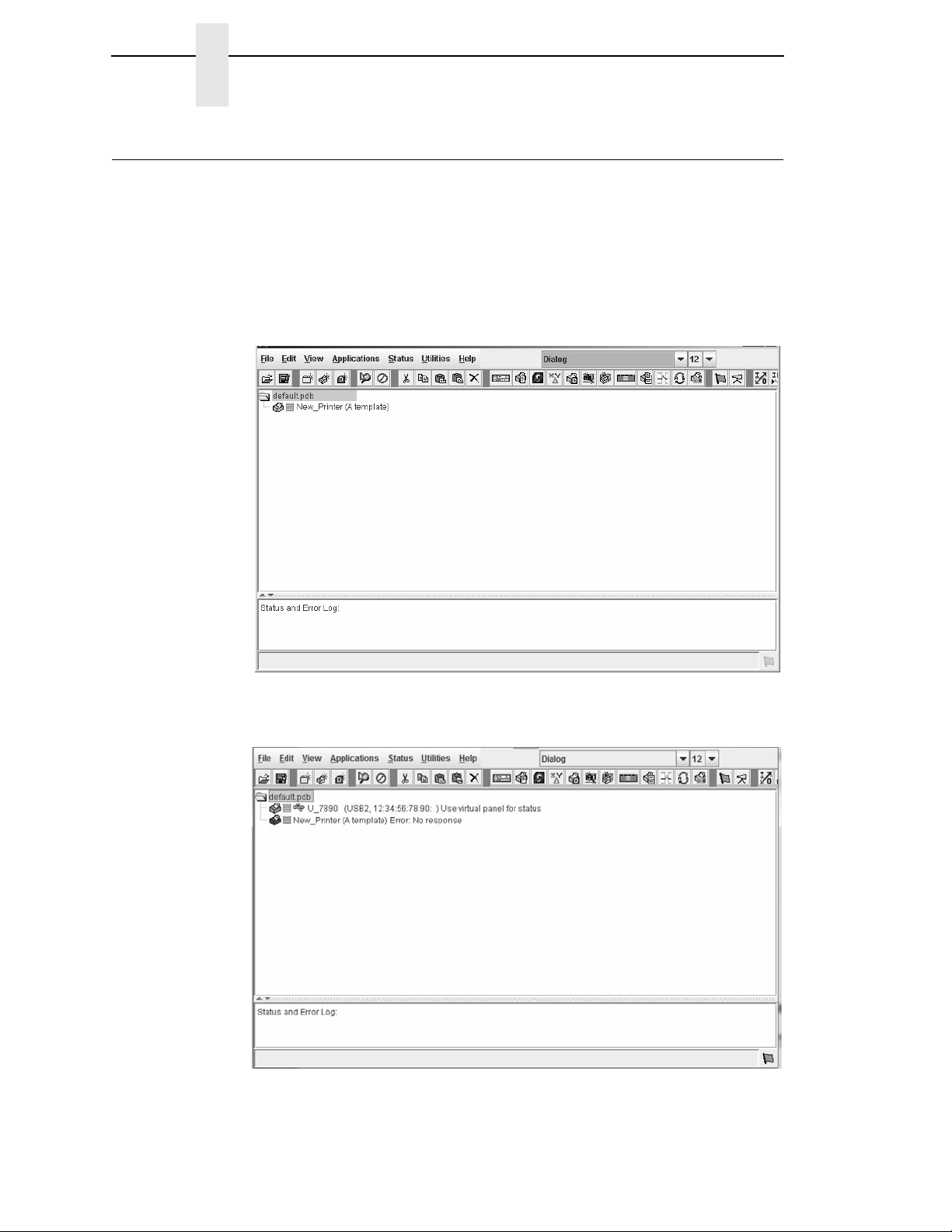
the main window of the printer database more clearly. See
Figure 1.
Figure 1. Printer Database Main Window
3. If your printer has USB connected to the PC, you will see the USB printer
device. See
Figure 2. Printer Database Main Window with USB Connection
Figure 2.
20
Page 21
Unix Setup
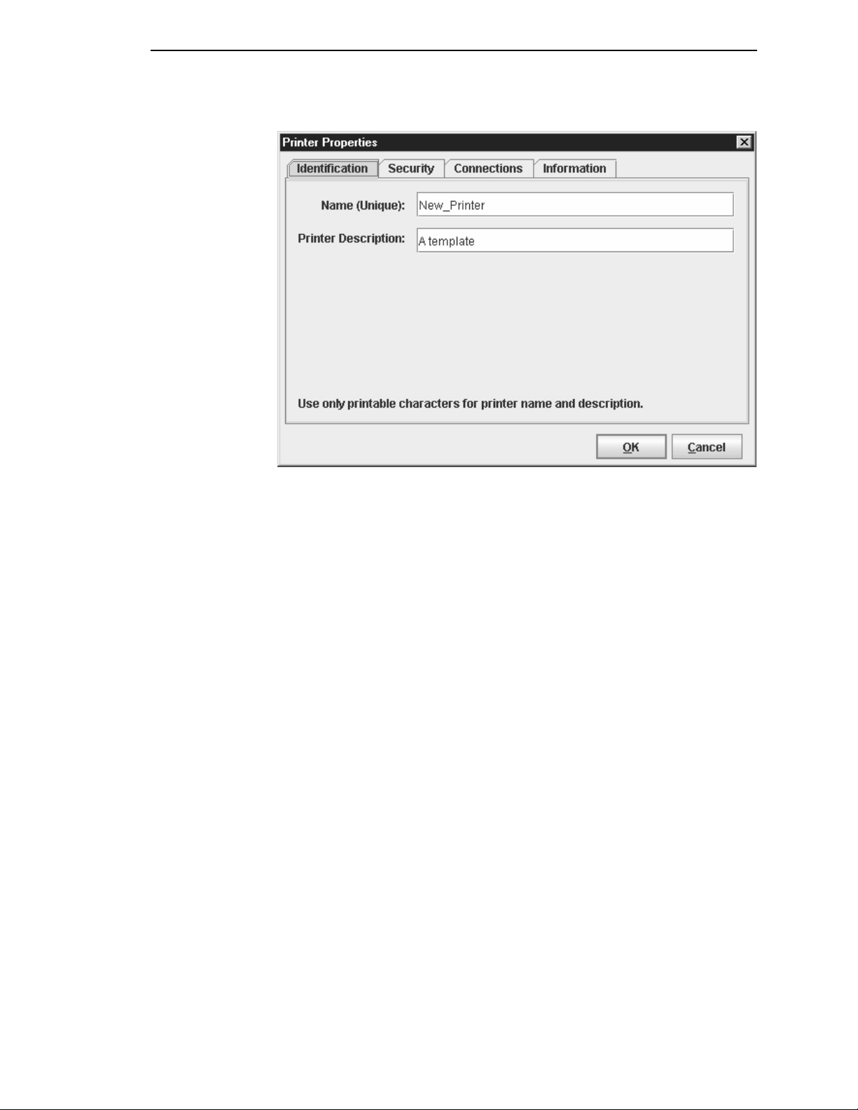
Figure 3. Printer Properties: Identification Tab
4. Double-click
box opens. See
5. Assign a name to your printer. Delete the words
Name (Unique) field, and then type
6. Assign a description to this printer. Delete the words
Printer Description field, and then type
New_Printer (A template)
Figure 3.
Tutorial
. The Printer Properties dialog
New_Printer
.
My First Connection
in the
A template
in the
.
21
Page 22
Chapter 1
Getting Started
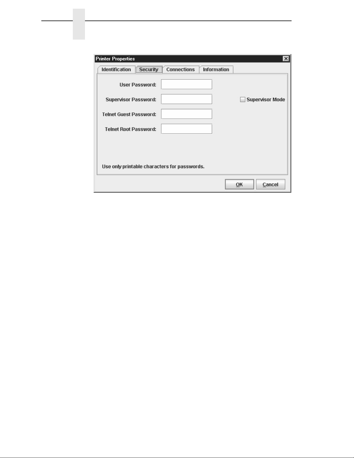
Figure 4. Printer Properties: Security Tab
7. Click the
8. If you are using PNE for the first time, it is likely that no passwords are
assigned to this printer. If you are unsure, contact your system
administrator.
•
If no passwords are assigned, leave the password boxes empty.
•
If a User password is necessary to access this printer, type the password
in the User Password field.
•
If a Supervisor password is necessary to access this printer, type the
password in the Supervisor Password field, and check the Supervisor
Mode check box.
•
If a Telnet guest password is necessary to poll the status of the printer,
type the password in the Telnet Guest Password field. See
on page 63.
•
If a Telnet root password is necessary to update wireless printer settings,
type the password in the Telnet Root Password field. See
on page 63.
In any case, an asterisk (*) character appears in the field after each letter
you type to preserve password secrecy.
For more details on setting up and changing passwords, see page 56.
Security
tab. See Figure 4.
“Security Tab”
“Security Tab”
22
Page 23
Unix Setup
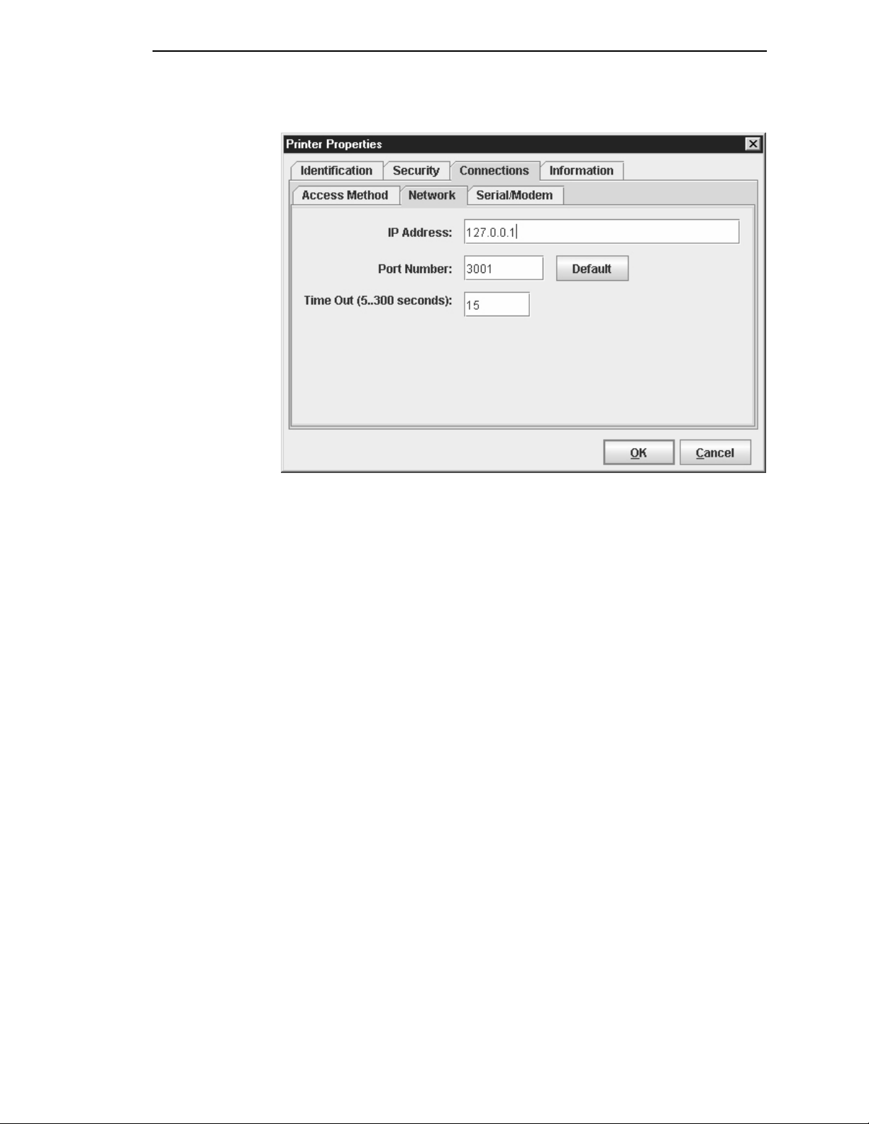
Figure 5. Printer Properties: Connections Tab – Network Sub-Tab
9. Click the
10. Click the
want to access. Follow the format shown in
The Port Number field must be set to the same port as the printer. Leave
it set at 3001. Leave the Time Out (5..300 seconds) field set at 15
seconds.
Connections
IP Address
field and then type the IP Address of the printer you
tab. By default, the Network sub-tab displays.
Figure 5.
23
Page 24
Chapter 1
Getting Started
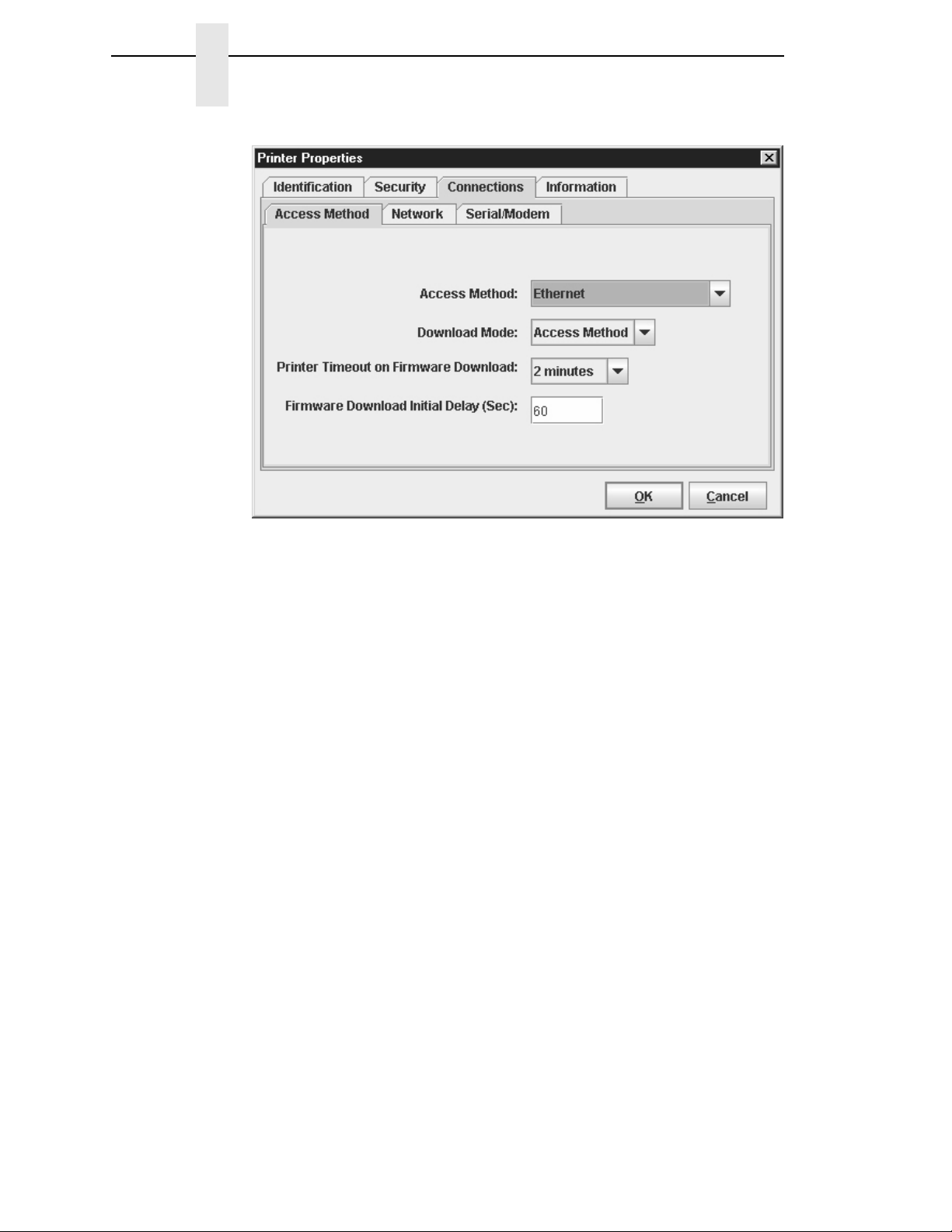
Figure 6. Connections: Connections Tab – Access Method Sub-Tab
11. Click the
The Access Method tells PNE how the host computer communicates with
the printer. Make sure it is set to Ethernet. Ignore Download Mode and
Download Timeout for now. These options are described in
Method Sub-Tab” on page 66.
Access Method
sub-tab. See Figure 6.
“Access
24
Page 25
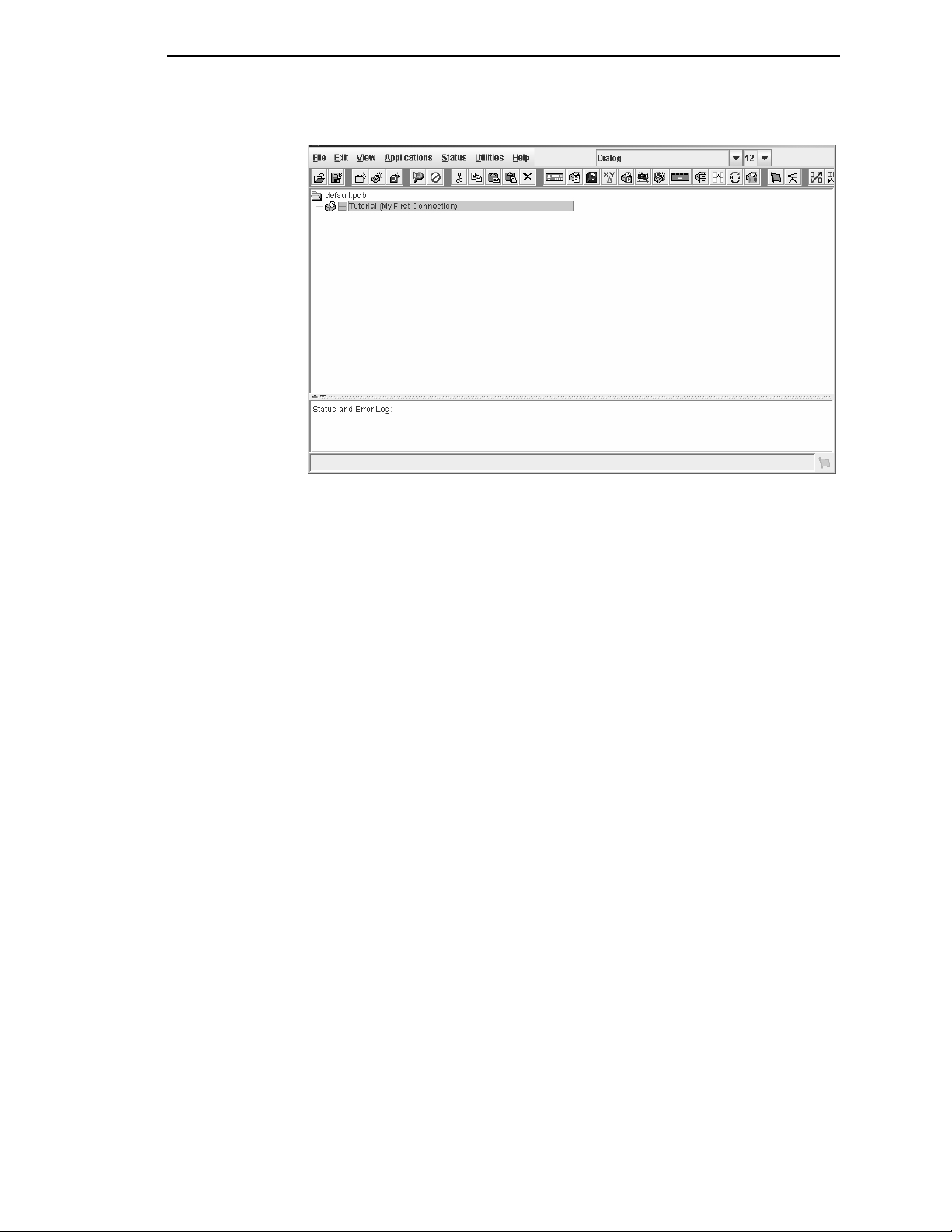
Figure 7. Printer Database Main Window
Unix Setup
IMPORTANT
12. Click OK. The Printer Properties dialog box closes and you return to the
printer database main window. See
the PNE database.
13. Try to access the virtual operator panel as a test to see if the information
you input is accurate. Follow this procedure:
a.
Tutorial (My First Connection)
shown in
b. Select
appears (see
message appears in the Status and Error Log pane. Check your
password to make sure it is correct. If the error continues, contact
your system administrator.
c. Printers connected via the USB interface are automatically detected
by PrintNet Enterprise. The USB interface cannot be manually
selected using the Access Method mentioned above. To ensure that
a USB connected printer is detected, the printer must have the PNE
Port set to USB. Make sure that USB Support is enabled under PNE
Preference. Refer to the Printer Setup section (
instructions on setting the PNE Port.
PNE will search for USB connected printers every minute when the
application is running.
Before starting PNE, make sure the printer is connected vi a USB and the
PNE Port setting is correct. Otherwise, the application may not find the
printer.
Figure 7. If it is not highlighted, click it to select it.
ApplicationsOperator Panel.
“Operator Panel” on page 113). If not, an error
Figure 7. Your printer is now set up in
should be highlighted in blue, as
The virtual operator panel
page 12) for
All USB connected printers that were detected is listed at the top of
the printer tree.
25
Page 26

Chapter 1
Getting Started
26
Page 27
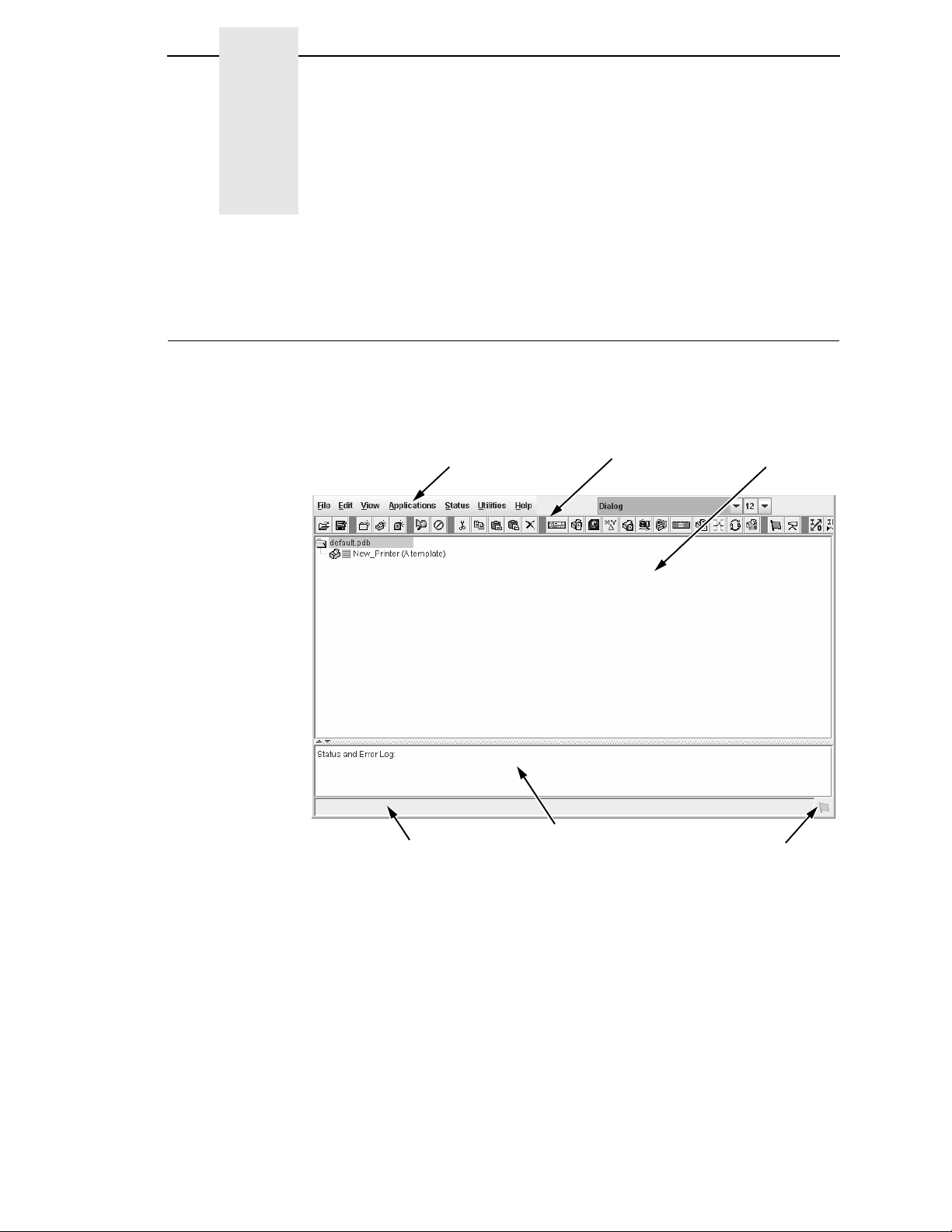
2
Menu Bar
Toolbar
Database Pane
Status and Error Log Pane
Status Bar
Polling Indicator
Overview
Printer Database
When you start PNE, the printer database window appears first. The printer
database tool organizes and controls printers and Download files.
shows how the database looks when PNE launches for the first time.
Figure 8
The menu bar contains all the menus used to control the functions of the
program. The menus are described later in this chapter.
The toolbar contains buttons for the most commonly used menu functions.
See
Use the Database pane to access and control your printers in a tree format.
The first line of the database tree displays the database file name. In
the default file name for this database is
database tree branches out to include printers, folders, and Download files,
which you can organize into groups. With a single mouse click, you can
download a file to several printers at once. In addition, you can use as many
Figure 8. Printer Database Main Window
page 58 for descriptions of the toolbar buttons.
default.pdb
Figure 8,
. From there, your
27
Page 28
Chapter 2
The Menu Bar
databases with PNE as you want. Databases save as
hard drive.
NOTE:
The Status and Error Log scrolls status and error messages as you work
through the program. If PNE does not function properly, look at this pane for
error messages. Use the scroll bar on the side of the pane to reference
previous status and error messages. The status and error messages relate to
the current PNE session, not to the specific database. When you exit PNE,
these messages will be deleted.
The Status Bar displays brief status messages of PNE, some of which appear
in the Status and Error Log.
The Polling Indicator turns green whenever printers are being polled.
The Menu Bar
The printer database menu bar is located at the top of the window
(see Figure 8). Use the menu bar to access all the functions of PNE.
The following are descriptions of the options located on the menu bar.
The File Menu
.pdb
You can open only one printer database at a time.
files on your local
28
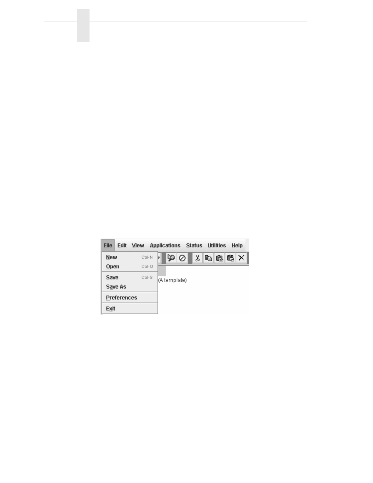
Figure 9. File Menu
New
Creates a new database file. Since PNE allows only one database file to be
open at a time, it asks if you want to save your changes to the current
database before it creates a new one.
Open
Opens a database file. Since PNE allows only one database file to be open at
a time, it asks if you want to save your changes to the current database before
it opens a different one.
Page 29
Preferences
Save
Saves the active database file using its current name.
Save As
Prompts you to enter a name for the current database file before PNE saves
it. Use Save As if you do not want to overwrite the current database file.
Preferences
Opens the Preferences dialog box. See page 29.
Exit
Exits PNE.
Preferences
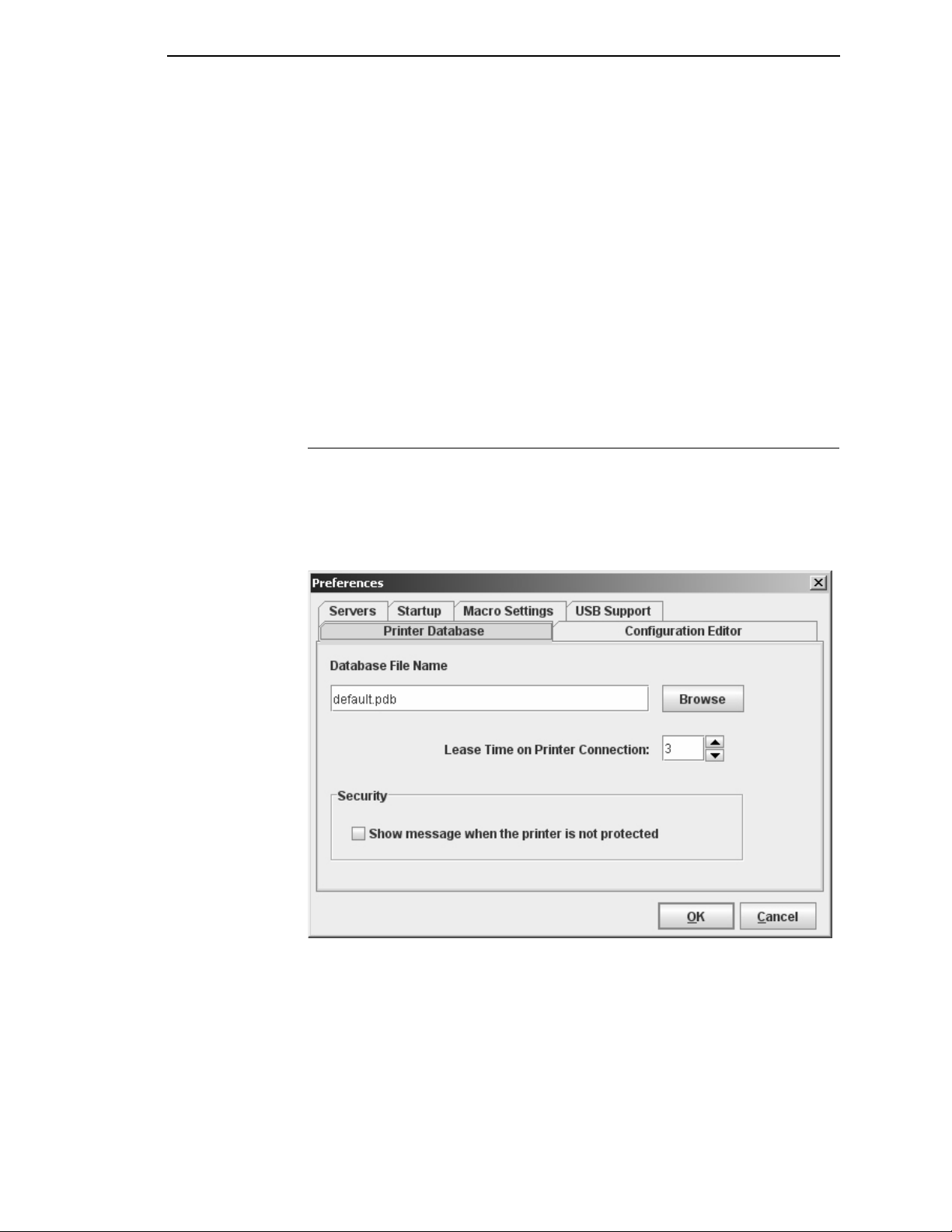
The Preferences dialog box has three tabs: Printer Database, Configuration
Editor, and Servers. See
Figure 10.
Printer Database T ab
Figure 10. Preferences: Printer Database Tab
The Printer Database tab controls database features.
Database File Name:
this database file when the program starts. To select a new default database
file, type it into the Database File Name field, or click
on your network.
Enter the name of the default database file. PNE opens
Browse
to locate a file
29
Page 30
Chapter 2
The Menu Bar
Lease Time on Printer Connection:
maximum amount of time a printer connection can remain open without any
communication. The default is three seconds.
Security:
check box to enable a warning message that informs you when a selected
printer does not have an assigned password.
Check the
Show message when the printer is not protected
Enter an amount (in seconds) to set the
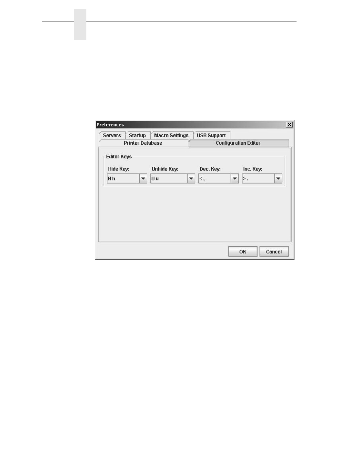
Configuration Editor Tab
Figure 11. Preferences: Configuration Editor Tab
The Configuration Editor tab controls features of the Configuration Editor
utility.
Hide Key/Unhide Key:
the Configuration Editor menu tree (see
The default for Unhide is U u.
Dec./Inc. Key:
in the Configuration Editor menu tree (see
decrement is < ,. The default for increment is > ..
Assigns which keys will decrement and increment menu items
Assigns which keys hide and unhide menu items in
page 71). The default for Hide is H h.
page 71). The default for
30
Page 31

Servers Tab
Preferences
Figure 12. Preferences: Servers Tab
The Servers tab allows you to assign port values for the SNMP (Simple
Network Management Protocol) Trap Server, the Web Server, and the XML
Server. Click
NOTE:
SNMP Trap Server:
printer when its status changes. Once PNE receives the alert, PNE creates an
instant status poll to reflect the change in the database pane. For instance, if
you turn the printer offline, the printer sends an alert to PNE causing it to
change the printer status instantly. In the database pane, the printer status
changes to offline.
NOTE:
Web Server:
“Web Access” on page 128.
NOTE:
XML Server:
Service Enabled
You must restart PNE to use the new settings and enable the servers.
The service that enables PNE to receive alerts from the
The SNMP Trap Server works only if the printer’s NIC is configured
correctly using the Configure Print Servers utility. See
Print Servers” on page 153.
Allows you to view the active PNE using a web browser. See
If you want to use the Web Server service, you must also enable the
XML Server service.
PNE uses XML to communicate with its web server.
next to the corresponding server to turn it on.
“Configure
31
Page 32

Chapter 2
The Menu Bar
Startup T ab
Figure 13. Preferences: Startup Tab
In the Startup tab, check the AutoID Data Manager check box to set the
AutoID Data Manager (
launches.
If you have added printers in the printer list (page 284), and the Run box is
checked, the AutoID Data Manager will launch and begin collecting telemetry
data automatically when PNE launches.
NOTE:
You must restart PNE to use the new settings.
page 281) to launch automatically when PNE
32
Page 33

Macro Settings Tab
Preferences
Figure 14. Preferences: Macro Settings Tab – General Sub-Tab
The Macro Settings tab has three sub-tabs: General, Network, and Serial.
See
Figure 14.
General Sub-Tab
Macro Config File:
you start the macro utility. To select a new default macro config file, type it into
the Macro Config File field, or click
Printer Port:
choices vary according to the host computer. Possible choices include LPT1,
LPT2, COM1, COM2, and Network.
If you select COM1 or COM2, click the
parameters. If you select Network, click the
network parameters.
• Use selected network printer:
the network printer selected in the printer database. You do not need to
further define network parameters.
• Rescan:
computer.
Displays the macro file that will load automatically when
Browse
Allows you to select the port that data is sent through. The
Check this box to send data directly to
Checks to see which ports are currently available on the host
to locate a file on your network.
Serial
tab to further define printer
Network
tab to further define the
33
Page 34

Chapter 2
The Menu Bar
Figure 15. Preferences: Macro Settings Tab – Network Sub-Tab
Network Sub-Tab
Use the Network tab only when the Printer Port on the General tab is set to
Network.
IP Address:
Port:
The port number that PNE will use to send the data. This must match
the network interface card (NIC) of the printer where PNE will send the data.
In most cases this is 9100, the default. If not, contact your system
administrator.
The address of the printer where PNE will send the data.
34
Page 35

Preferences
Figure 16. Preferences: Macro Settings Tab – Serial Sub-Tab
Serial Sub-Tab
Speed:
speed of the printer host serial port under the SERIAL PORT menu (thermal
printers) or the SERIAL submenu in the HOST INTERFACE menu (all other
printer models). See “Serial Port” (thermal) or “Host Interface” (all others) in
your
Word Size:
be set to 8.
Stop Bits:
Parity:
Other settings include Mark and Space.
Flow Control:
to the needs of the receiving side.
• None:
• Rts/Cts in:
• Rts/Cts out:
• Xon/Xoff in:
The baud rate at which data transfers. This setting must match the
User’s Manual
The number of data bits per character. In most cases this should
Inter-character gap. Can be set to 1 or 2. The normal setting is 1.
Adds an error checking bit if set to Odd or Even. The default is None.
No adjustment occurs.
X-off control characters.
.
Prevents data overrun by adjusting the sending side according
Hardware flow control on serial-input.
Hardware flow control on serial-output.
Software flow control on serial-input using the X-on and
• Xon/Xoff out:
X-off control characters.
Software flow control on serial-output using the X-on and
35
Page 36

Chapter 2
The Menu Bar
Figure 17. Preferences: USB Support Tab
IMPORTANT
USB support is disabled by default. It can be enabled by using the Preference
setting under the File menu. In the Preference dialog, click the USB Support
tab and make sure that the box “USB Support Enable” is checkmarked.
Restart PNE to en able the new USB sett ing.
The Edit Menu
Figure 18. Edit Menu
Use the Edit option on the menu bar to build your database. The options in the
Edit menu are described below.
36
Insert
Adds a folder, printer, or Download file into your database. You must select an
existing database item to create a folder, printer, or file. You can also paste
the contents of the paste buffer (the last item that was copied or cut) into the
database. The new icon appears one level below the selected database item.
If there are items below the selected database item, the new item appears at
the end.
Page 37

The Edit Menu
Inserting an item involves three steps:
1. Select a database item. (The new icon will appear below the item you
select.)
2. Define which type of icon you want to add. Select
select the item you want to add. Or click the
(insert new printer), or (insert new Download file) icon.
A new icon appears in the database.
3. Define what printer, folder, or file this icon represents.
a. To define a printer, see “Defining Printer Properties” on page 61.
b. To define a folder, double-click
box opens. Type the name of the folder and click
c. To define a Download file, see “File Download” on page 91.
New Folder
EditInsert
(insert new folder),
. The Folder Name dialog
OK
.
and then
Cut
Removes selected folders, printers, or files from the database and places it in
the paste buffer.
Copy
Copies selected folders, printers, or files from the database to the paste
buffer, leaving the original intact.
NOTE:
You can select multiple database items by using the
Ctrl
or
Shift
key.
Paste
Places the item in the paste buffer on the database tree. To paste, you must
select a database item. The pasted item appears on the same level as the
selected database item.
NOTE:
If you select
as the selected database item. However, if you select
Paste Buffer
database item.
EditPaste
, the pasted item appears one level below the selected
, the pasted item appears on the same level
EditInsert
Delete
Permanently removes a selected folder, printer, or file from the database.
Include/Exclude
Deactivates a selected folder, printer, or file. Inactive database items display a
red circle with a slash through it on top of the item’s icon.
You cannot send information to or receive information from excluded
database items using the following Applications, Status, and Utilities menu
options: Flash File Manager, File Download, Update Status, and Configure
Print Servers.
To activate a database item, select the inactive item and then select
EditInclude/Exclude
.
37
Page 38

Chapter 2
The Menu Bar
The View Menu
Figure 19. View Menu
Collapse Tree
Collapses all folders on the database menu tree. Only the top level menu
items display.
Expand Tree
Expands all folders and printers on the database menu tree. All folders,
printers, and Download files display.
38
Page 39

Style
The View Menu
Angled Lines:
Shows the links between database items using angled lines.
Horizontal Lines:
Figure 20. Angled Lines
Shows the links between folders using horizontal lines.
Figure 21. Horizontal Lines
39
Page 40

Chapter 2
The Menu Bar
No Lines:
Shows no lines between database items.
Figure 22. No Lines
40
Page 41

Toolbar
Allows you to select which buttons display on the toolbar.
The View Menu
NOTE:
For a description of the toolbar icons, see “The Toolbar” on page 58.
By default, some icons do not appear in the toolbar.
Figure 23. Customize Toolbar
41
Page 42

Chapter 2
The Menu Bar
The Applications Menu
Figure 24. Applications Menu
For an explanation of the Applications menu options, find the menu option in
Table 2 and go to the corresponding page.
Table 2. Applications Menu Options
Menu Option Page
Configuration Editor page 71
Flash File Manager page 87
CST Manager page 155
File Download page 91
GPIO Manager page 209
Media Profiler page 105
Operator Panel page 113
Information Capture page 119
Factory Differences page 82
42
AutoID Data Manager page 281
ODV Quality Wizard page 122
Speed Keys page 123
Job Capture page 124
Page 43

The St atus Me nu
Discover Printers
The Status Menu
Figure 25. Status Menu
To search for printers on a network, select
click the
results of the search display in the database pane.
Discover Printers searches for printers on a network based on the settings
specified in the Discovery tab of the Status Monitoring Properties dialog box.
The next section explains how to configure your search.
Discover Printers
button at the far right of the toolbar. The
StatusDiscover Printers
, or
43
Page 44

Chapter 2
The Menu Bar
Properties
Select
box. The dialog box contains three tabs: Discovery, Polling, and Alert
Delivery.
NOTE:
StatusProperties
To enable printer discovery, check the
check box.
to open the Status Monitoring Properties dialog
Enable Printer Discovery
44
Figure 26. Status Monitoring Properties:
Discovery Tab – Print Server Discovery Sub-Tab
Discovery Tab
You can discover printers on a network in three ways:
1.
Print Ser ver Discovery:
printers on a subnet. To enable the option, check the
Server Discovery
box (see
Response Wait (Seconds):
waits for a printer response. By default, the value is set at 5 seconds.
Broadcast IP, Subnet Mask
match your network configuration. See your system administrator.
NOTE:
Figure 26), then click
To discover unconfigured NICs, you must enter the Gateway Address
and Subnet Mask in the Return Gateway field.
This option allows you to discover all PrintNet®
Enable Print
check box in the Status Monitoring Properties dialog
Apply
or OK.
To specify the time delay (in seconds) PNE
, and
Return Gateway:
These settings must
Page 45

The Status Menu
Figure 27. Print Server Discovery in Progress
If Enable Print Server Discovery is enabled, a progress indicator displays
while PNE discovers printers. See
Figure 27.
45
Page 46

Chapter 2
The Menu Bar
Figure 28. Status Monitoring Properties:
Discovery Tab – Polled Discovery Sub-Tab
2.
Polled Discovery:
addresses to poll. To enable the option, click the
and check the
Figure 28). In the First IP Address field, enter the first IP address of your
desired range. In the Last IP Address field, enter the last IP address. Click
Apply
or OK. PNE polls the printers within your specified range and
displays the results in the database pane.
If Polled Discovery is enabled, a progress indicator displays while PNE
discovers printers. See
This option allows you to select a range of IP
Polled Discovery
Enable Polled Discovery
Figure 29.
check box, then click
Add
tab
(see
46
Figure 29. Polled Discovery in Progress
Page 47

The Status Menu
Figure 30. Status Monitoring Properties:
Discovery Tab – Known Printers Discovery Sub-Tab
3.
Known Printers Discov ery :
printer IP addresses. From this log, you can select and delete previously
polled discoveries to create a new polling list to target your printer search.
To enable the option, click the
the
Enable Known Printers Discovery
the polled list of IP addresses, refine your search by keeping or deleting
found IP addresses. Click
specification.
NOTE:
You cannot manually add an IP address to this list. If you delete an IP
address, it is lost until it is rediscovered.
If Known Printers Discovery is enabled, a progress indicator displays
while PNE discovers printers. See
This option logs previously discovered
Known Printers Discovery
check box (see Figure 30). From
Apply
or OK to start a new poll based on your
Figure 31.
tab and check
Figure 31. Known Printers Discovery in Progress
47
Page 48

Chapter 2
The Menu Bar
Polling T ab
Figure 32. Status Monitoring Properties: Polling Tab
The Polling option allows you to control the way PNE polls printers on the
network. For instance, you can create a timed interval for PNE to poll every 30
seconds or every two minutes. You can also specify a range of IP addresses.
To enable the option, check the
Polling tab (see
between each SNMP request. This feature minimizes the network load. By
default, the value is set at 100 milliseconds (.1 second).
NOTE:
Now you can set parameters to a new task. The parameters include:
Printer/Folder:
the field to select options from a drop-down menu.
First IP:
you select
Last IP:
select
If Discovery is enabled, then a discovery also occurs, based upon the
settings in the Discovery tab (see
To set the beginning IP address in a polling range. Use this option if
To set the last IP address in a polling range. Use this option if you
Range:
Figure 32). The SNMP Pacing (MS) value places a delay
To select which printer or folder you want PNE to poll. Click
Range:
as the Printer/Folder option.
as the Printer/Folder option.
Enable Status Monitoring
“Discovery Tab” on page 44).
check box in the
48
Page 49

The Status Menu
Enable:
If you want PNE to poll the printers according to the specifications of your first
task, select
Initial Delay (S):
PNE polls printers. The time delay is calculated in seconds.
Polled Interval (S):
calculated in seconds. Use this option to periodically poll for new printers
every few seconds.
Response Wait (MS):
responses. By default, the value is set at 300 milliseconds (.3 seconds).
NOTE:
NOTE:
To select whether or not you want to enable polling of a specific task.
true
. Otherwise, select
To specify the time delay from when PNE starts to when
To poll printers automatically with timed intervals
To specify the time delay PNE waits between SNMP
If your network is overloaded and the responses are slow, you may
not receive a response with the default setting. In this case, increase
your Response Wait (MS) value.
If you enter a low value for slow networks, you may receive no
response. In this case, increase the Response Wait (MS) value.
false
.
49
Page 50

Chapter 2
The Menu Bar
Alert Delivery Tab
Figure 33. Status Monitoring Properties:
Alert Delivery Tab – Alert Log Sub-Tab
Select
box. Click the
to enable the option. The Alert Delivery properties allow you to customize the
way PNE notifies you of potential printer errors. Descriptions of the three alert
types follows:
1.
StatusProperties
Alert Delivery
Alert Log:
directory. To log alerts, check the
Add
specify the following as applicable, then click
Allows PNE to log alerts to a file located in the PNE installation
(see Figure 33). A task item adds to the log list. In the task item,
Log File:
Size:
minimum required) size is 1000 bytes.
Device:
folder, specific printer, or a range of IP addresses.
First:
option if you select
Last:
you select
To name the log file. The default file name is
To set the maximum file size, in bytes. The default (and
To choose a device item you want PNE to monitor, such as a
To set the beginning IP address in a polling range. Use this
To set the last IP address in a polling range. Use this option if
Range:
to open the Status Monitoring Properties dialog
tab. Check the
Range:
as the Device option.
as the Device option.
Enable Notification
Enable Log File
Apply
check box, then click
or OK.
check box
alerts.log
.
50
Page 51

The Status Menu
NOTE:
In the remaining alert option fields, select
desired.
Offline, Warning, Media Input, Media Output, Media Path, Marker
Cutter, Barcode, RFID, Scanner, Label, Intervention Needed
Consumables
and printer events, refer to “Alert Groups” in the SNMP Configuration
section of chapter three in the
All options are enabled by default.
To set up alert groups on the NIC, see “Configure Print Servers” on
page 153.
Comment:
, and
Power Cart:
Enter comments as needed.
For a description of the alert groups
Network Interface Card User’s Manual
enable
or
disable
as
,
,
.
Figure 34. Status Monitoring Properties:
Alert Delivery Tab – Email Alerts Sub-Tab
2.
Email Alerts:
set up Email Alerts, check the
in the following fields:
Outgoing Mail (SMTP) Server:
Email Subject:
Email Sender:
SMTP Email Server Port:
PNE sends you an alert e-mail if a printer error occurs. To
Enter the subject of e-mail.
Enter your e-mail address.
Enable Email
See your system administrator.
See your system administrator.
check box. Enter information
51
Page 52

Chapter 2
The Menu Bar
Next, click
specify the following information, then click
NOTE:
Add
to define a new task (see Figure 34). In the new task item,
Email Address:
send the alert messages.
Device:
folder, specific printer, or a range of IP addresses.
First:
option if you select
Last:
you select
In the remaining alert option fields, select
desired.
Offline, Warning, Media Input, Media Output, Media Path, Marker,
Cutter
Consumables
and printer events, refer to “Alert Groups” in the SNMP Configuration
section of chapter three in the
All options are enabled by default.
Comment:
To choose a device item you want PNE to monitor, such as a
To set the beginning IP address in a polling range. Use this
To set the last IP address in a polling range. Use this option if
,
Barcode, RFID, Scanner, Label, Intervention Needed
Enter the e-mail address where you want PNE to
Range:
Range:
Enter comments as needed.
as the Device option.
, and
as the Device option.
Power Cart:
Apply
or OK.
enable
For a description of the alert groups
Network Interface Card User’s Manual
or
disable
as
,
.
52
Figure 35. Status Monitoring Properties:
Alert Delivery Tab – Syslog Posting Sub-Tab
Page 53

The Status Menu
3.
Syslog Posting:
alerts to a file located in the PNE installation directory. To log alerts,
check the
task item adds to the log list. In the task item, specify the following as
applicable, then click
Enable Syslog
Used in a UNIX operating system, it allows PNE to log
check box, then click
Apply
or OK.
Add
(see Figure 35). A
NOTE:
Machine Address:
Port:
See your system administrator.
Device:
as a folder, specific printer, or a range of IP addresses.
First:
option if you select
Last:
you select
In the remaining alert option fields, select
desired.
Offline, Warning, Media Input, Media Output, Media Path, Marker
Cutter, Barcode, RFID, Scanner, Label, Intervention Needed
Consumables
and printer events, refer to “Alert Groups” in the SNMP Configuration
section of chapter three in the
All options are enabled by default.
Comment:
To choose a device item that you want PNE to monitor, such
To set the beginning IP address in a polling range. Use this
To set the last IP address in a polling range. Use this option if
Range:
Enter comments as needed.
The UNIX IP Address.
Range:
as the Device option.
, and
as the Device option.
Power Cart:
Network Interface Card User’s Manual
enable
For a description of the alert groups
or
disable
as
,
,
.
53
Page 54

Chapter 2
The Menu Bar
Update St atus
Update Status shows the condition of the printer at the time the status is
checked. To update the status of a printer, select
click the
Figure 36 shows a printer with a wireless NIC that uses two ports. The
(signal strength) icon represents the wireless port, while the (ethernet
port) icon represents the ethernet port.
The printer’s model number, if available, displays in brackets following the
printer icons. Current OEM printers display the OEM’s model number if it is
placed in the Printer MIB. Future OEM printers (rebranded Printronix printers),
will not show the model number or the brackets after the printer icons.
The printer name is a user defined field that is used to distinguish a printer in
the database. This field can be modified in the Printer Properties dialog box
under the Identification tab. The name chosen must be unique from all the
other printer names in the database and must use printable ASCII characters.
(green flag) button at the right of the toolbar.
StatusUpdate Status
, or
Figure 36. Update Status
When the printer status updates, the (printer) icon may change color:
•
Green indicates the printer is online, functioning properly, and can print
•
Yellow indicates a warning, but the printer can print
•
Red indicates the printer is offline or not functioning properly and cannot
print
•
Grey indicates that the printer is not recognized
The message to the right of the printer description is identical to the message
on the operator panel.
If you enable status polling, the printer status updates automatically.
The (ribbon supply) icon indicates the amount of ribbon remaining on the
printer.
•
Green indicates a full or nearly full ribbon supply
•
Yellow indicates a moderate ribbon supply
•
Red indicates a small or no ribbon supply
•
Grey indicates one of the following:
•
The ribbon supply feature is not supported on the printer
•
For thermal printers, the printer is not using ribbon but rather direct
thermal
54
•
For thermal printers, the printer has not printed since it was powered
on, so PNE cannot determine the amount of ribbon remaining
Page 55

The Status Menu
•
For line matrix printers, the printer was powered on with a fault
condition (not allowing the ribbon to be activated), so PNE cannot
determine the amount of ribbon remaining
•
For line matrix printers, the amount of ribbon remaining has reached 0%
(you can still print depending on the operator panel settings)
NOTE:
The (signal strength) icon indicates the strength of the radio signal.
•
•
•
The (ethernet port) icon always remains blue, since it represents an
ethernet connection.
The (battery power) icon indicates the percentage of available battery
power.
•
•
•
Place the pointer over the , , or icon to obtain status information
about the feature. See Figure 37, Figure 38, and Figure 39 on page 55.
NOTE:
The following three icons appear only if the features are installed.
Green with three or four bars indicates a strong signal
Yellow with two bars indicates a moderate signal
Red with one bar indicates a weak or non-existent signal
Green indicates the battery has 61% to 100% available power
Yellow indicates the battery has 20% to 60% available power
Red indicates the battery has less than 20% available power
No information displays if you place the pointer over the icon.
The status information provided by PrintNet Enterprise varies based
on the printer mode and/or the printer connection method. All USB
connected printers will not have its status updated. To see the current
printer status, use the virtual front panel. For T2N printer models, only
basic status information will be available: Online or Offline.
Figure 37. The Ribbon Supply Icon
55
Page 56

Chapter 2
The Menu Bar
Figure 38. The Signal Strength Icon
Figure 39. The Battery Power Icon
The Utilities Menu
Figure 40. Utilities Menu
For an explanation of the Utilities menu options, find the menu option in
Table 2 and go to the corresponding page.
56
Page 57

Table 3. Utilities Menu Options
Menu Option Page
Reboot Printer page 135
Set Printer Password page 135
Set Wireless Properties page 137
Macro Utility page 146
SNMP Browser page 149
Assign IP Address page 150
The Help Menu
Enable Remote Printer
Management
Lock/Unlock Menus page 152
Configure Print Servers page 153
page 151
The Help Menu
Figure 41. Help Menu
User’s Manual Location
Displays the User’s Manual Location dialog box. This dialog box tells you
where to find the PNE user’s manual PDF file.
About
Displays the About dialog box. The About dialog box shows the PNE
program’s version information and part number, and the Java version
number.
57
Page 58

Chapter 2
The Toolbar
The Toolbar
The PNE toolbar contains buttons that perform functions. See below for a
description of each button. Refer to the specified page for a more detailed
description.
You can select which buttons display on the toolbar. See page 41.
Button Description
Open:
Opens a different printer database.
Save:
Saves the current printer database.
Folder:
(
Printer:
(page 36).
Download File:
database (
Edit:
(
Include/Exclude:
or file (
Cut:
database and places it in the paste buffer (
Copy:
paste buffer (
Paste After:
selected item (
Paste Into:
selected item (
Delete:
Inserts a new folder into the printer database
page 36).
Inserts a new printer into the database
Inserts a new Download file into the
page 36).
Defines the properties of the selected item
page 61).
Deactivates a selected folder, printer,
page 37).
Removes a selected folder, printer, or file from the
page 37).
Copies a selected folder, printer, or file to the
page 37).
Pastes the item in the paste buffer after the
page 37).
Pastes the item in the paste buffer into the
page 37).
Removes the selected item (page 37).
58
Operator Panel:
to make selections via PNE as if you are using the
physical operator panel (
Information Capture:
information sent between the computer and the printer
(
page 119).
Configuration Editor:
from the computer to the printer before the printer
receives it (
Virtual operator panel that allows you
page 113).
Allows PNE to capture
Allows you to edit the data sent
page 71).
Page 59

Button Description
The Help Menu
Find Differences:
from the factory settings for all configurations (
File Download:
firmware, or flash file to the printer (
ODV Quality Wizard:
window (
Configure Print Servers:
Servers window (
Speed Keys:
(
page 123).
Flash File Manager:
window (
Media Profiler:
(
page 105).
CST Manager:
(
page 155).
Job Capture:
(
page 124).
page 122).
page 87).
Allows you to find the differences
Allows you to download a configuration,
page 91).
Opens the ODV Quality Wizard
Opens the Configure Print
page 153).
Opens the Speed Keys window
Opens the Flash File Manager
Opens the Media Profiler window
Opens the CST Manager window
Opens the Job Capture window
page 82).
Macro Utility:
(
page 146).
Update Status:
updates (
Discover Printers:
GPIO Manager:
(
page 209).
AutoID Data Manager:
Manager window (
Opens the Macro Utility window
Marks a printer or printers for status
page 54).
Searches for new printers (page 43).
Opens the GPIO Manager window
page 281).
Opens the AutoID Data
59
Page 60

Chapter 2
Folder:
Use folders to group the elements of your database.
Printer:
See “Defining Printer Properties” on page 61.
Download file:
A flash file or a configuration file (created in the
Configuration Editor which is described on page 71) stored on your
host computer.
A flash file contains information (e.g., the printer’s firmware file or a font
file) that you can download to the flash SIMM memory of a printer or
group of printers.
A configuration file contains user-defined printer configurations that you
can download to your printer using either the printer database or the
Configuration Editor.
For information about Download files, see “File Download” on page 91.
Managing the Database
Managing the Database
To organize your databases easily and effectively, use the Edit option on the
printer database menu bar. You can add, delete, and assign printers,
configuration files, and download files to your database tree. You can also
organize them using folders. All Edit menu functions have buttons on the
toolbar (see
Database Items
page 58).
60
Page 61

Defining Printer Properties
Defining Printer Properties
Figure 42. Defining Printer Properties
Before you can use any of the PNE applications, you must define the printer’s
properties. You must identify the printer and configure how the printer
communicates with PNE. To define a printer, double-click the printer’s name
or click the
double-click
opens. See
The Printer Properties dialog box contains four tabs: Identification, Security,
Connections, and Information, described in the next sections.
If the printer is USB connected, the Printer Properties dialog box displays the
Security tab only. See
(edit database entry) button. The first time you run PNE,
New_Printer (A template)
Figure 42.
Figure 43.
. The Printer Properties dialog box
Figure 43. Defining Printer Properties for a USB Connected Printer
61
Page 62

Chapter 2
Managing the Database
Identification Tab
Figure 44. Printer Properties: Identification Tab
Name (Unique)/Printer Description:
identify it in the printer database. You can also assign a printer description,
which appears in parentheses to the right of the printer name in the database.
When you assign a printer name and description, use only printable
characters. Spaces may be used to separate words.
Assigns a name to your printer to
62
Page 63

Security Tab
Defining Printer Properties
IMPORTANT
IMPORTANT
Figure 45. Printer Proper ties: Security Tab
User/Supervisor Password:
The password feature restricts access to certain functions of PNE. In User
mode, PNE does not allow the following functions: downloading files,
configurations, or configuration names to the printer; clearing the error log;
and setting passwords. Supervisor mode allows unrestricted access to all
functions of PNE.
User and Supervisor passwords are only recognized up to 9 characters, and
are displayed as *****, one * for each character typed. Use only printable
characters for passwords. Spaces may be used to separate words. To set up
a password, see
Telnet Guest Password:
If you change the Telnet guest password, click OK and then the
(green flag) button (or select StatusUpdate Status).
Telnet Root Password:
If you change the Telnet root password, click OK and then the
(green flag) button (or select StatusUpdate Status).
“Set Printer Password” on page 135.
Enter the printer’s password, if appropriate.
PNE uses Telnet to read various printer settings.
PNE uses Telnet to update various printer settings.
63
Page 64

Chapter 2
Managing the Database
Telnet Guest Password Errors
Figure 46. Telnet Guest Password Error: Polling the Printer Status
PNE uses Telnet to poll the printer status. If your printer reports a Telnet error
(see
Figure 46), enter the password for the user
See your system administrator.
guest
(page 63).
64
Figure 47. Telnet Guest Password Error: Reading Wireless Settings
PNE also uses Telnet to read wireless printer settings (page 137). If PNE
reports a Telnet error when attempting to read wireless printer settings
(see
Figure 47), enter the password for the user
See your system administrator.
guest
(page 63).
Page 65

Telnet Root Password Errors
Figure 48. Telnet Root Password Error
Defining Printer Properties
If PNE reports a Telnet error when attempting to update wireless printer
settings (see
See your system administrator.
PNE also uses Telnet to enable remote printer management (see “Enable
Remote Printer Management” on page 151).
If PNE reports an error when attempting to enable remote printer
management (see
See your system administrator.
Figure 48), enter the password for the user
Figure 49. Enable Command Failed
Figure 49), enter the password for the user
root
(page 63).
root
(page 63).
65
Page 66

Chapter 2
Managing the Database
Connections Tab
Figure 50. Printer Properties:
Connections Tab – Access Method Sub-Tab
The Connections tab contains three sub-tabs: Access Method, Network, and
Serial/Modem.
Access Method Sub-Tab
Access Method:
Network Interface Card User’s Manual
• Ethernet:
• Network (TCP):
network interface.
• Printer Serial Port (Direct):
printer directly via the serial port.
• Printer Debug Port (Direct):
printer directly via the debug port.
• Printer Serial Port (Modem):
printer via a modem and the serial port.
• Printer Debug Port (Modem):
printer via a modem and the debug port.
Identifies how PNE accesses the printer. Refer to the
to set up the NIC for your printer.
To connect the host computer to the printer via the NIC.
To connect the host computer to the printer via a
To connect the host computer to the
To connect the host computer to the
To connect the host computer to the
To connect the host computer to the
66
Page 67

Defining Printer Properties
Download Mode:
the printer. Access Method is the only option available.
Printer Timeout on Firmware Download:
the printer waits for data while downloading a file from the host computer. If a
stall lasts for more than the specified time, the printer times out and the
download terminates. If you have a slow connection between PNE and the
printer, you may need to define a longer Download Timeout period.
The Download Timeout range is between 1 and 60 minutes. The default is
2
minutes.
Firmware Download Initial Delay (Sec):
PNE waits before sending files to the printer. If the printer is not ready within
the specified time, the download will terminate, and the Status and Error Log
will report Connection Refused.
If you receive this error message, increase the initial delay time. The default is
60 (seconds).
Identifies how PNE downloads files and configurations to
Specifies the number of minutes
Specifies the number of seconds
Network Sub-Tab
Figure 51. Printer Properties: Connections – Network Sub-Ta b
Enter the printer’s IP Address and Port Number. (Click
Port Number to 3001.) The Time Out option sets the amount of time, in
seconds, PNE waits for a response from the printer after sending a command.
If there is no response in the specified amount of time, an error message
appears in the Status and Error Log pane. If you have a slow connection
between PNE and the printer, you may need to define a longer Time Out
period. Define the Time Out between 5 and 300 seconds (the default is 15
seconds).
Default
to reset the
67
Page 68

Chapter 2
Managing the Database
NOTE:
The Network settings must match the settings in the operator panel
menu. See “ETHERNET PARAMS”, “ETHERNET ADDRESS”, or
“WIRELESS ADDRESS” in the printer’s
IP address.
To check the port number on the printer, see “Check Port Number” on
page 17.
User’s Manual
to check the
Serial/Modem Sub-Tab
The Serial/Modem tab contains two tabs: Serial Port Parameters and Modem
Control.
NOTE:
P8000 printers do not have PNE serial connectivity.
Serial Port Parameters
68
Figure 52. Printer Properties: Connections – Serial/Modem Sub-Tab
Serial Port Parameters
Connect Using:
The range is COM1 to COM20.
The serial port to use for connection. The default is COM1.
Page 69

Defining Printer Properties
Speed:
speed of the printer serial debug port. See
debug port baud rate menu location for your printer model
Word Size:
Parity:
must be set to 8 for correct operation, parity should normally be set to None.
Stop Bits:
The baud rate at which data transfers. This setting must match the
Table 4 to determine the serial
Table 4. Serial Debug Port Baud Rate Menu Location
Printer Model Menu
SL4M/T4M INTERFACESPrinter MgmtBaud Rate
SL5000r/T5000r PRINTER MGMT or FactoryBaud Rate
SL5000e/T5000e FactoryBaud Rate
P7000 PRINTER MGMTBAUD RATE
P5000 FactoryPRINTER MGMTBAUD RATE
The number of data bits per character. Must be set to 8 bits.
Adds an error checking bit if set to Odd or Even. Since the word size
Inter-character gap. Can be set to 1 or 2. The normal setting is 1.
Modem Control
Figure 53. Printer Properties: Connections – Serial/Modem Sub-Tab
Modem Control
Phone Number:
Dial Method:
Call Back:
as a call back number.
Enter the phone number you wish to call.
Choose Tone or Pulse.
Enter your phone number, and check Enable if you want to use it
69
Page 70

Chapter 2
Managing the Database
Information Tab
Figure 54. Printer Properties: Information Tab
Contains information about your printer. Refer to the
User’s Manual
for more information.
Network Interface Card
70
Page 71

3
Applications and
Configuration Editor
Web Access
Figure 55. Configuration Editor Window
To access the Configuration Editor application, select a printer from the
printer database and select
(configuration editor) button. Select
configurations from the printer. The configurations upload from the printer and
the active configuration displays in the Configuration Editor window. See
Figure 55.
The Configuration Editor supports offline editing, allowing the editing of stored
configurations. If you start the Configuration Editor without connecting to a
printer, the screen will be blank (indicating no configuration loaded). A
configuration will not display until you load a configuration file from a disk or
computer.
The Configuration Editor allows you to upload, modify, and download eight
user-defined configurations and the factory default configuration (only if
modification of the factory configuration has been enabled; see the NOTE on
page 73). You may also save sets of configurations to your local hard drive so
that they can be easily downloaded to the printer at any time.
The Configuration Editor does not change the current configuration or the
active printer status until the configurations are downloaded to the printer.
ApplicationsConfiguration Editor
FileUpload From Printer
or click the
to upload
71
Page 72

Chapter 3
Configuration Editor
Menu T re e
The Configuration Editor displays the printer configurations in a tree format
(see
Figure 55). The top level of the tree is the OFFLINE menu. From this
level, the tree branches into the printer’s submenus. Menu items that have a
or (handle) next to them have further submenus below them. Click the
handle to expand or collapse the submenus below. (You may also use the
Expand Tree/Collapse Tree options in the View menu, but these options will
expand or collapse all submenus.)
The Configuration Editor has three drop-down menus at the bottom. The
Displayed Language option allows you to select from five or more different
languages to display the configuration information. The Displayed
Configuration option lets you choose between the available configurations to
display. The Power-Up Configuration allows you to assign which configuration
loads whenever the printer turns on.
Creating Configurations
Along with the factory configuration, your printer allows up to 8 user-defined
configurations that can be downloaded to your printer’s memory. You may
create configurations using the operator panel or by using the Configuration
Editor.
To create a configuration using the Configuration Editor:
1. Select
configurations appear gray. Choose one of the configurations.
2. Click
next to the Copy From: menu item.) Move your mouse down to
A list of configurations appears. Choose the number of the configuration
you want to create. This new configuration is created with the settings
from the configuration you chose in
NOTE:
3. You may now edit the configuration settings. See “Changing
Configurations” on page 73.
EditCopy From:
Edit
. (Notice that the configuration you chose in step 1 now appears
If you choose to
configuration will be overwritten.
. A list of configurations appears. Undefined
step 1.
Copy To
a configuration which already exists, that
Copy To
.
72
Page 73

Changing Configurations
Changing Configurations
Configuration settings in the Configuration Editor can be changed two ways:
•
make the changes directly on the menu tree
•
use the Menu Editor
NOTE:
Making Changes on Menu Tree
1. Using the Displayed Configuration menu at the bottom of the window,
2. Expand the submenus until the configuration setting you want to change
Normally, the factory default configuration cannot be changed.
However, you can enable modification of the factory configuration.
Select
you do
modify the factory configuration, you should first upload it from the
printer, and then save it. This way, you will have a backup copy of the
factory configuration. To disable modification of the factory
configuration, select
click the drop-down arrow to choose the configuration to change.
displays.
EditEnable Factory Edit
not
modify the factory default configuration. If you choose to
EditDisable Factory Edit
. It is strongly recommended that
.
3. Select the menu item you want to change. A selection box surrounds your
choice. See
4. Double-click an item to open the Menu Editor (page 74) for that item, or
use the < and > keys to toggle through the available options. See
Figure 57. (You may change these keys in the printer database window:
select
See page 30.)
Figure 56.
Figure 56. Selecting a Menu Item
FilePreferences
Figure 57. Toggling Through The Available Options
, then click the
Configuration Editor
tab.
73
Page 74

Chapter 3
Configuration Editor
Menu Editor
Figure 58. Menu Editor
Double-click any menu item to open the Menu Editor window. Figure 58
shows the screen you see when you double-click the Printer Protocol option.
By using the Menu Editor, you may view and adjust the settings of all nine of
the printer configurations at once. To change a setting, click the drop-down
arrow underneath the corresponding configuration and choose an option.
Grayed out configuration names and settings do not exist; you must create
the configuration before you can edit it (see
To hide a menu item in the operator panel, select Hidden under a
configuration. Click
more information on hiding, see
Select
factory or user-defined configuration currently selected under the
EditCopy From: menu in the Configuration Editor (see page 72).
Click
Click
Click OK to save your changes and exit the Menu Editor.
Copy Fact (1-8)
Cancel
Apply
to save your changes without exiting the Menu Editor.
Hide All
to exit the Menu Editor without saving your changes.
to hide this menu item in all configurations. (For
page 75.)
to set all configurations to the same value as the
page 72).
Deleting Configurations
To delete any of the configurations (except the factory configuration), select
EditDelete
and choose the number of the configuration to be deleted.
74
Naming Configuratio ns
You may name any of the eight user-defined configurations using an
alphanumeric string of 1 to 15 characters. Select
Edit Configuration Names window.
Choose the configuration you want to name, then click OK to assign the name
change,
restore the original configuration numbers.
Cancel
to exit this window without saving your changes, or
EditNames
to open the
Reset
to
Page 75

Hiding/Unhiding Menu Item s
Changing Configurations
IMPORTANT
Figure 59. Hiding a Menu Item
The Configuration Editor allows you to hide menus to make the operator
panel menus easier to use, or to restrict printer operators from accessing
certain printer configuration menu items. If you choose to hide a menu item in
the Configuration Editor, the hidden menu item still loads into the printer when
the configuration downloads to it. However, the hidden menu item does not
appear on the operator panel.
The Configuration Editor displays hidden menus in gray on the menu tree.
When a menu item is hidden, all of its sub-menus are hidden as well.
In Figure 59, the Display Language menu item is hidden. The Display
Language menu item cannot be changed from the operator panel.
Depending upon the active emulation, active interface, or hardware
attached to the printer, some menu items cannot be hidden on the
operator panel, even though they may be defined as “hidden” in PNE.
You can still change hidden menu items using the Menu Editor.
You can hide or unhide menu items in three ways:
1. In the menu bar, select
option, you may hide or unhide individual items, sub-menus or the entire
configuration.
2. Using the Menu Editor. See page 74.
3. Using the keyboard. From the menu tree, select a menu item. A selection
box appears around the selected menu item. Press
item or
FilePreferences
U
to unhide the menu item. (To change these keys, select
ViewHide/Unhide Menus
in the printer database window. See page 30.)
. With this menu
H
to hide the menu
75
Page 76

Chapter 3
Configuration Editor
Saving Configuration Files
Normally, your printer can save only nine configurations in its memory. You
change these configurations through the operator panel. However, using
PNE, you can store a nearly unlimited number of configurations on your host
computer.
Once you have made your changes, you can save your configurations as a
.cfg
file on your local hard drive. This way, you can open any set of
configurations from your host computer and download them into your printer
quickly and easily.
To save configurations to your local hard drive, select
to save your configuration as a
It may be necessary to save a configuration file in the format used by previous
versions of PNE. In this case, select “Legacy Configuration File” from the
Files of Type: list and select the file to be saved.
.cfg
file.
FileSave As
. Be sure
76
Figure 60. Saving as a Legacy Configuration File
Page 77

Opening Configuration Files
Opening Configuration Files
IMPORTANT
To open a configuration file, select
loads the settings from the file you choose.
These settings do not affect the current configuration or the active
printer status until the configurations are downloaded to the printer.
NOTE:
If you load a configuration file that was created with PNE version 3.03H or
earlier, you may need to link the affiliated CST file. In this case, select
FileOpen
Navigate to the affiliated
the
save to the new configuration file. (You will not need to link the CST file in the
future.)
NOTE:
The Configuration Editor displays only one configuration file at a time.
Be sure to save any changes before opening another configuration file.
again, and check the
.cst
Select
button). Save the configuration file, and the CST information will
If you hover the pointer over the
tip appears that describes this functionality.
FileOpen
Link CST File
file and double-click it (or single-click it and click
. The Configuration Editor
check box. See Figure 61.
Link CST File
check box, a screen
Figure 61. Linking a CST File
77
Page 78

Chapter 3
Configuration Editor
Downloading Configurations
You may use the Configuration Editor to download into your printer any
configurations you have created. Open the configuration file you want to use,
then select
configurations, or just the configuration names.
Downloading a configuration overwrites the corresponding configuration
currently stored in the printer. If you want to save the configurations currently
stored in the printer before overwriting them, upload them into the
Configuration Editor first, and then save them as a
drive.
FileDownload To Printer
to send individual configurations, all
.cfg
file on your local hard
NOTE:
NOTE:
Be sure to calibrate your thermal printer after you download a
configuration to it. See “Running Auto Calibrate” in the printer’s
User’s Manual
Downloading a configuration file does not immediately update the
printer’s active configuration. You must activate a downloaded
configuration using the Load Config. setting in the operator panel.
Refer to the printer’s
.
User’s Manual
for details.
Uploading Configurations
The Configuration Editor can upload configurations from a printer. Select
FileUpload From Printer
them to a file. Now you can select another printer from the database and
upload its configurations. PNE prompts you to save the previously uploaded
configuration before the new configuration uploads.
. Once the configurations upload, you can save
Migration
Over time, menus and functions changed to reflect the new features of the
printers. Some printer features have been removed to provide better or more
complete printer features. Older saved configurations may have used these
removed features or contain settings that no longer exist or have been
modified in new printer firmware. This can cause potential problems when
downloading new printer firmware while preserving previously saved
configurations if the saved settings are not analyzed and adjusted to work
with the new firmware. This analysis and adjustment has been summarized
into one word: migration.
78
T ransferring Saved Settings
Original Method
To ensure that your settings from the saved configuration are set correctly in
the printer: print out the old configurations, download the configurations to the
printer, print out the new configurations, and compare the old settings with the
new settings.
If you need to make changes: upload the configurations to the Configuration
Editor, make changes, and re-download to the printer.
Page 79

Migration
Enhanced Method
Using the migration utility in the Configuration Editor, all these things can be
done without having to download the configurations to the printer until you
know they are correct. No migrated settings will be downloaded to your printer
until you download them. This way you can run the migration, view the results,
view the report, and make any necessary changes without affecting your
saved configurations or the configurations in the printer.
How To Use The Migration Utility
STEP 1:
Load the configurations settings that need to be migrated into the
Configuration Editor before using the migration utility.
Migration Limitations
Only attempt to migrate saved configuration settings from printers of the same
model type and the same emulations. An example of a different printer model
type is a thermal printer configuration to a line matrix printer.
The printer that you are going to migrate the settings to should be a superset
of or contain the same emulations as the saved configurations. For example,
migrate saved settings that contain an ANSI emulation on a line matrix printer
to another line matrix printer that contains ANSI and PGL. Do not migrate
these same saved settings to a line matrix printer that does not contain ANSI.
The migration utility does not prevent you from doing this, but the results
would be useless and could cause problems if the migrated configurations
were downloaded and then loaded on a different printer type.
IMPORTANT
Make sure the printer model type and emulations of the saved
configurations match the printer model type and emulations of the
printer you want to migrate the settings to before attempting to migrate
the saved settings.
Loading Configuration Settings
The configuration settings to migrate can be opened using the Configuration
Editor in the following ways:
Loading From a File
Click the (open configuration file) button or select
your configuration file and then click OK.
Loading From a Printer
Select a printer in the printer database. Click the (upload configuration)
button or select the
FileUpload From Printer
FileOpen
to upload the settings.
. Choose
79
Page 80

Chapter 3
Configuration Editor
STEP 2:
Select a printer and begin the migration of the saved configuration
settings.
Select a Printer to Use for Migration
Select a printer in the printer database. The printer you select must have new
printer firmware. If it does not, exit the Configuration Editor and download new
firmware to the selected printer (see
the printer in the printer database.
Start the Migration
“File Download” on page 91), then select
Click the (migrate) button or select
messages will appear in the bottom left corner of the Configuration Editor that
indicate the progress of the migration.
MigrationRun Migration
. Several
STEP 3:
View the results using the Configuration Editor.
The results will display graphically in the Configuration Editor.
Several different icons will display depending on the migration. Hover the
pointer over an icon to display a short description. A icon can represent
several types of changes. The migration report details these changes
(
page 81).
Select
This menu has the following submenus:
Original Configurations
All Menus:
were removed from the original configurations.
Removed Menus:
original configurations.
Migrated Configurations
MigrationView Results
Displays the original configuration settings with the menus that
Displays only the menus that were removed from the
to see the migration results.
80
All Menus:
menus that were modified.
Modified Menus:
migration of the saved settings.
If you select
menus that were affected by the migration will display in a simplified view.
Displays the migrated configuration settings including all of the
Displays only the menus that were modified by the
Modified Menus
and then select
ViewExpand Tree
, all of the
Migration Icon Definitions
Indicates a new menu or a new set of menus.
Indicates that the menu previously existed in the saved configurations and
was added to another menu.
Page 81

Migration
Indicates that the menu previously existed in the saved configurations and
was moved to another menu, or removed from the current menu but still exists
in the saved configurations.
Indicates that the menu was completely removed.
Indicates that this menu or a submenu has changed. The change can be
various things such as range or increment.
Indicates that additional selections have been added to this menu.
Indicates that selections have been removed from this menu.
Indicates that this menu has been replaced with another menu or the
menu definition has changed.
STEP 4:
View the results using the Migration Report Viewer.
IMPORTANT
Select
icon (located at the top of the migrated configurations display) to open the
Migration Report Viewer.
The Migration Report Viewer displays a detailed textual report of the
information that displays graphically in the Configuration Editor. Use the
Migration Report Viewer to view, save, or print the report.
NOTE:
The report contains the following types of messages:
Informational Messages:
They display to inform you that there was a change during the migration.
Warning Messages:
configurations and were changed. Analyze these settings to determine if they
are desirable.
Intervention Messages:
configurations. This could occur when a menu item was completely removed
and the user utilized a setting other than the default. In this case the Migration
Utility cannot decide what action to take.
You must resolve intervention messages, or the printer may not operate
properly.
MigrationView Report
It is recommended to use landscape mode when printing the
migration report.
Menu settings that attempted to migrate to the new
Menu settings that could not migrate to the new
or double-click the
Menu settings that migrated without problems.
Migration Report
STEP 5:
Post-migration.
After you review the migrated configuration, save, delete, or download the
migrated configuration file to one or more printers using PNE.
81
Page 82

Chapter 3
Configuration Settings
Differences Pane
Menu Bar
Toolbar
Factory Settings Differences
Factory Settings Differences
The Factory Settings Differences application allows you to keep track of
migration from old to new printers. It displays the differences between the
Factory configuration settings and all other saved configuration settings. The
differences are highlighted to show value differences between configurations.
Two views displaying the data are available. The All Settings view shows all of
the menus, highlighting the value differences. The Differences Only view
shows the menus and its corresponding values that differ from the Factory
settings.
To access the Factory Settings Differences application, select
ApplicationsFactory Differences
The application opens with no configuration data loaded. The Factory
Settings Differences window contains three sections: the menu bar, toolbar,
and the configuration settings differences pane. See
or click the (find differences) button.
Figure 62.
Figure 62. Factory Setting Differences Window
82
Page 83

Menu Bar
The menu bar consists of a File menu and a View menu.
File Menu
Menu Bar
Figure 63. Factory Settings Differences – File Menu
Open
The Open submenu allows you to select and open a previously saved Factory
Settings Differences file. The file must be one that was created with this
application.
NOTE:
No error checking is available for an invalid file type, including
Comma Separated Variable (CSV) formatted files that were not
created by this application.
Upload Differences
The Upload Differences submenu uploads the configurations and determines
the Factory settings differences. The results display in a table in the All
Settings view.
Save and Save As
The Save and Save As submenu allows you to select and save the Factory
setting differences file to a file. The results table can only be saved in the
Differences Only view. You will be informed if you try saving the file in the All
Settings view. The saved file will be in CSV format.
Print
The Print submenu allows you to set up printing preferences and print the
differences table. You can print the differences table in both views.
83
Page 84

Chapter 3
Factory Settings Differences
View Menu
Figure 64. Factory Settings Differences – View Menu
All Settings View
The All Settings view displays all of the menus in the configuration,
highlighting the menus that are different from the Factory settings and their
values. The menu name and its associated values are highlighted in different
colors for easy distinction. See
Differences Only View
page 85.
The Differences Only view shows the top level menus and the menus that
have configuration values that are different than the Factory settings. Since
this view only shows the differences, the menu names are not highlighted.
The menu values are highlighted for easier distinction. See
page 86.
Toolbar
Figure 65. Factory Settings Differences – Toolbar
The toolbar contains buttons for Open, Save, Upload Differences, All Settings
View, Differences Only View and Print. These buttons perform the same
actions as their menu counterparts. The toolbar also has font selection and
size boxes to allow user selectable preferences.
84
Page 85

Configuration Settings Differences Views
Configuration Settings Differe nces V iew s
This view consists of a non-editable table that displays the menu name, the
menu level, the Factory default settings, and the values of other saved
configurations.
The menu level column shows a menu option’s hierarchy level from the top
menu. Number 1 indicates the top menu, and the largest number is the menu
that is the furthest down the menu tree.
All Settings View
In the All Settings View mode, all menus and its corresponding values display
in a table. The menus with values different from the Factory configuration is
highlighted in purple and the value itself is highlighted in yellow.
See Figure 66.
Figure 66. All Settings View
85
Page 86

Chapter 3
Factory Settings Differences
Differences Only View
In the Differences Only View mode, only the differences between the Factory
configuration and other menu configurations are listed. The differing values
are highlighted in yellow. The menus are not highlighted.
Figure 67. Differences Only View
Displayed Language
The Displayed Language drop-down menu shows all available foreign
languages that the attached printer supports. Since this depends on the
printer, the drop-down menu will be disabled when the Factory Settings
Differences application is first launched. After the Upload Differences program
is executed, the available language names supported by the printer will
display.
After you select a language, the program determines if it has already been
uploaded, and changes the table settings to this language. If it is not loaded,
the program uploads the selected language and redisplays the table settings
in the new language.
86
Page 87

Flash File Manager
Display ed Language
Figure 68. Flash File Manager Window
With the Flash File Manager, you can view a list of the unprotected files
loaded in the printer’s flash memory and optional EM (External Memory).
NOTE:
You can upload the files to the host computer, save them for backup, delete
them, and download them to another printer.
Select
manager) button. See Figure 68.
The Printer List pane displays a list of printers that are selected in the printer
database. If you select one printer, it appears alone in the list. If you select a
folder, all active printers in the folder appear.
If you return to the printer database and select another printer or folder, click
Refresh
printer(s).
NOTE:
The EM is available only for SL4M/T4M and P8000 printers.
ApplicationsFlash File Manager
to update the Flash File Manager and display the newly selected
Cloned printers or different folders that link to the same printer do not
display. Only the original printer displays.
or click the (flash file
87
Page 88

Chapter 3
Status Bar
Flash File Manager
Get File Inf o
Figure 69. Get File Info
Select a printer, and then click
files loaded in the printer’s flash memory. Progress displays in the status bar
at the bottom of the window. After you retrieve the flash memory information,
the files appear in the File List pane. See
NOTE:
When complete, select another printer and click
memory information.
You can only view the flash memory information from one printer at a time,
but the Flash File Manager remembers what information has been retrieved.
For printers that have not had flash memory information loaded, the message
FFS (Flash File System) Info Not Loaded displays in the Printer List.
See
NOTE:
The status bar will toggle from the status of the last operation performed to
the status of the printer flash: memory available (free), memory used (in use),
and memory deleted but not optimized (trashed):
The files are located on the printer’s internal flash memory. If [EM]
precedes the file name, then the file is located on the optional EM.
Figure 69.
Although you have retrieved the flash memory information, the files
have not been uploaded. Notice the message “data not loaded” in the
File List. To upload the files, see
Get File Info
Figure 69.
“Upload” on page 89.
to see a list of the unprotected
Get File Info
to view its flash
If you have an EM installed, the status bar will also toggle the status of the
EM:
88
Page 89

Upload
Upload
Figure 70. Uploaded Flash Files
To upload unprotected files, select a printer, and then select the files you want
to upload from the File List. Click
the flash memory. Progress displays on the status bar at the bottom of the
window.
After the files upload, they appear selected in the File List pane. See
Figure 70. Click
file (bundle file). Save the file with a
Save As
to save all the files together as one downloadable
Upload
.pff
to upload the unprotected files from
file extension.
89
Page 90

Chapter 3
CST Manager
Or, you may use the
See Figure 71. This way, only the selected files will save to the
you click
NOTE:
Delete And Optimize
IMPORTANT
You can not undo a flash file deletion.
You can erase files from the printer’s flash memory. Select the files you want
to delete from the File List, then click
flash memory, see
Once you have deleted files, the flash memory is not optimized until you click
Optimize
NOTE:
To delete and optimize in one step, select the files you want to delete from the
File List, then click
CST Manager
Figure 71. Selecting Multiple Files
Shift
or
Ctrl
key to select single or multiple files.
Save As
You can save only uploaded files to a downloadable file.
. Optimizing reclaims flash space from deleted flash files.
The printer reboots after you Optimize.
.
Delete
“File Download” on page 91.
Delete & Optimize
.
. To download files back to the
.pff
file when
90
See “Datastream Adapter” on page 155.
Page 91

File Download
Delete And Optimize
IMPORTANT
NOTE:
To utilize the File Download application, make sure Enable Status
Monitoring is checked in the Polling tab (see
printer in the printer database and click the update status button to
make sure your printer has been polled at least once (see page 54).
The File Download application allows you to download any of the following file
types (program files, configuration files, recovery files, and flash files) to either
a single printer or to a group of printers in one step. Recovery files are an
exception and should only be downloaded back to the printer that had
problems during a download.
To download a file to a single printer, insert a (Download file) icon below
the printer (one level lower than the printer). To download a file to a group of
printers, insert the Download file icon on the same level as the printers (in the
same folder containing the printers). Use the printer database and insert
additional Download file icons to download as many files to as many printers
as you want.
NOTE:
The terms
indicate the printer’s point of view. Therefore, when you download a
file, you are sending information to the printer (the printer downloads).
When you upload a file, you are receiving information from the printer
(the printer uploads).
Previous versions of PNE required different file types to be
downloaded to the printer in separate steps, which is why the various
file types were identified by
software, a distinction between the various file types is not needed,
and a
database that was saved using a previous version of the software, all
icons will change to icons.
download
icon identifies all file types. Therefore, if you open a printer
and
upload
as used here and in the software
page 48). Then select your
or icons. With this version of the
91
Page 92

Chapter 3
File Download
Define th e Do w nlo ad Fi le s
After you insert Download files, you must define them:
1. Double-click
box opens. See Figure 72.
2. Click
3. Navigate to a program (firmware), configuration, recovery file, or flash file,
4. Since multiple file types can now be downloaded in one operation, a
Browse
select it, then click
button is provided to allow you to verify if the file type specified is
supported by the printer. Clicking the
the specified file and display the file type – this will help you verify that you
selected the correct file. Click
Cancel
to terminate, or click
New Download File
. The Open dialog box opens.
Figure 72. Define Download File
Open
.
OK
Browse
. The Define Download File dialog
Test
button causes PNE to evaluate
if the file type returned is correct, click
to select another file.
Test
92
5. When you are finished, click OK. The database displays the path and
name of the program, configuration, recovery or flash file.
Page 93

Download the Files
Download the Files
After you define Download files in your database, you must download them to
your printer for them to affect the active print state.
NOTE:
To begin the download process, select a printer or a folder containing printers
and select
icon. The File Download dialog box opens and displays a list of all the printers
that you selected in the printer database. See
Each emulation used by the printer has its own list of valid flash files it
can use. Refer to the appropriate
for details about valid flash files.
ApplicationsFile Download
Programmer’s Reference Manual
, or click the (file download)
Figure 73.
NOTE:
The following are the download options for each printer:
Firmware:
Restore Config:
printer once the Program File download has been completed.
If you later select a different printer or folder in the printer database
and the File Download dialog box is still open, click
update the list of printers.
Figure 73. File Download
Check this box to download the printer firmware (program file).
Check this box to restore the configurations that were in the
Update List
to
Restore Flash:
printer before the Program File was downloaded.
Config File:
Flash Files:
For each printer listed, various combinations of these operations can be
executed. Some combinations are mutually exclusive. For example, PNE
does not allow you to simultaneously preserve the printer’s configurations and
download a new configuration file to the same printer (you cannot check both
Restore Config and Config File for the same printer). Similarly, you cannot
restore configurations or flash files unless you are downloading new program
files.
NOTE:
You can double-click a field name (e.g., Firmware, Config File, etc.) to
check or uncheck the check boxes for all displayed printers at once.
Check this box to restore the flash files that were in the
Check this box to download a new configuration file.
Check this box to download additional flash files.
93
Page 94

Chapter 3
NOTE:
Displays only if
the printer has
an EM installed
File Download
Printer's SD card:
take a while. To avoid printer network connection time outs, change the
printer print job timeout setting to indefinite. The printer print job timeout is
different from the “Network Time Out” described in
page 34.
To change the printer print job timeout, telnet to the printer and type ‘store
pserver opts jobtimeout 0' and 'reset'.
Using PNE to download files to the printer SD card may
“Network Sub-Tab” on
Viewing the File Destination
Select a printer in the File Download dialog box and click
Update Properties dialog box opens. See
Figure 74.
Properties
. The
IMPORTANT
94
Figure 74. Update Properties
The Update Properties dialog box lists all the files that will be downloaded to
the selected printer, the source of the files, and their destinations:
Printer Flash (a single file to the printer’s flash memory) or Multiple Files to
Printer Flash. Also, if the printer supports the EM: External Memory (a single
file to the EM), Multiple Files to External Memory, or Both Printer Flash and
External Memory.
PNE can only download files to the EM through the NIC.
Page 95

Download the Files
Changing the File Destination
If you have the optional EM and you wish to change the destination of a single
file, click
Destination
. The User Files dialog box opens. See Figure 75.
Select
NOTE:
Printer Flash
Bundle files (archives that contain multiple files, usually with a
extension) cannot have their destinations changed. Files within
bundle files will download to the printer’s flash memory, the EM, or
both, depending on their original location.
or EM to specify the new destination.
.pff
IMPORTANT
Figure 75. User Files
Restoring Configurations and Flash Files
Whenever a printer downloads a program (firmware) file, the configurations
and flash memory are erased. You can choose whether or not to restore the
configurations and/or flash memory to what was previously loaded. Check or
uncheck the Restore Config check box for configurations and/or the Restore
Flash check box for flash files. By default, the configurations and flash
memory will restore.
If you uncheck Restore Config or Restore Flash, the configurations or
flash memory will erase when you initiate a program file download.
NOTE:
If you are downloading a program file and flash files, the Flash Files and
Restore Flash check boxes will be checked. The flash files will restore, but
they will be overwritten if the new flash files you are downloading have the
same name.
If a download fails due to a power interrupt or a severed connection, the
configurations and flash files will be lost and will not restore. You can
still restore the printer using the recovery file, but only if Restore Config
and/or Restore Flash was checked.
See “Recovery File” on page 104.
95
Page 96

Chapter 3
File Download
Figure 76. Download in Progress
Confirm that the correct files will be sent to the appropriate printers. Close the
dialog box to cancel the download and start over.
IMPORTANT
Click
Start
to begin the download. Once the download is in progress, click
Abort
or close the dialog box to abort the download. See Figure 76.
Aborting a download may leave the printer in an unstable state.
Before any operations begin, PNE obtains the printer type from the printer
and compares it with the printer type in the firmware file. If the types do not
match, PNE aborts the operation and shows an error message in the File
Download status window.
During the download, the printer’s flash memory will be erased, and
CLEARING FLASH will display on the operator panel. At this time, PNE may
appear to stop operating. This is normal, and the entire download process
should take no more than fifteen minutes.
NOTE:
You can also download a series of files to several printers at once using
folders. Select a folder and select
appropriate files inside the selected folder download to all of the printers
inside that folder.
NOTE:
See page 97 for examples of using the printer database and the File
Download application to download files.
Be sure to calibrate your thermal printer after you download a
configuration to it. See “Running Auto Calibrate” in the printer’s
User’s Manual
Downloading a configuration file does not immediately update the
printer’s active configuration. You must activate a downloaded
configuration using the Load Config. setting in the operator panel.
Refer to the printer’s
.
ApplicationsFile Download
User’s Manual
for details.
. All of the
96
Page 97

Downloading Examples
Download the Files
Figure 77. Sample Database
In this sample printer database (Figure 77), the printers are organized
according to different parts of the building. Each area contains its own printers
and Download files.
In the Manufacturing folder, two printers share the same program and
configuration Download files, the Area 1 printer has a flash Download file (in
this example, a fonts file), and the Area 2 printer has no flash Download file.
In the Administration Office folder, two printers share a program Download
file, the Vending Room printer has a configuration and a flash Download file,
and the Conference Room printer has no configuration or flash Download file.
The Building B and Building C folders are collapsed.
97
Page 98

Chapter 3
File Download
Figure 78. File Download: Conference Room Printer
Example 1
IMPORTANT
In this example, the user selected the Conference Room printer, then
selected
button. The File Download dialog box opens. See Figure 78.
The Conference Room printer will download a program (firmware) file, and the
configurations and flash memory will restore
If you uncheck Restore Config or Restore Flash, the configurations or
flash memory will erase when you initiate a program file download.
ApplicationsFile Download
or clicked the (file download)
98
Page 99

Example 2
Download the Files
Figure 79. File Download: Vending Room Printer
In this example, the user selected the Vending Room printer, then selected
ApplicationsFile Download
File Download dialog box opens. See Figure 79.
The Vending Room printer will download a program (firmware), configuration,
and flash file, and the flash memory will be restored.
To see a summary of the files the printer will download, double-click the
printer or select the printer and click
or clicked the (file download) button. The
Properties
.
99
Page 100

Chapter 3
File Download
Figure 80. Update Properties for the Vending Room Printer
The Update Properties dialog box opens. See Figure 80.
In this example, the Vending Room printer will download the Printer
Software B.prg program file, the Vending Configs.cfg configuration file, and
the Fonts.pff flash file.
100
 Loading...