

PRESONUS ULT-series Owner's Manual
ULT-series
Loudspeakers
Owner’s Manual
www.presonus.com
®
Français
Español
Deutsch
English


Table of Contents
1 Overview — 1
1.1 Introduction — 1
1.2 About This Manual — 1
1.3 Summary of ULT-Series Loudspeaker Features — 2
1.4 What is in the Box — 3
2 Getting Started — 4
2.1 Level Setting Procedure (Full-Range) — 4
2.2 Level Setting Procedure (ULT18) — 7
3 Hookup — 11
3.1 Rear-Panel Connections and Controls — 11
3.2 Onboard Performance Monitoring — 13
3.3 Power — 13
3.4 Hookup diagrams — 14
4 Loudspeaker Placement and System Configuration — 15
4.1 Recognizing Problem Rooms — 15
4.2 System configuration suggestions — 17
4.3 Rigging and Safety — 21
5 Technical Information — 24
5.1 Specifications — 24
5.2 Optional Accessories — 25
6 Troubleshooting and Warranty — 26
6.1 Support and Troubleshooting — 26
6.2 Warranty — 27

1 Overview
1.1 Introduction
ULT-series
Owner’s Manual
1
1 Overview
1.1 Introduction
Thank you for purchasing a PreSonus® ULT-series Active Loudspeaker. PreSonus
Audio Electronics has designed ULT-series Loudspeakers utilizing high-grade
components to ensure optimum performance throughout the life of your PA
system. The ULT-series loudspeakers are active PA speaker systems that provide
the widest horizontal dispersion in their class, thanks to the custom Pivot X110
horn. Compact and lightweight, they provide a powerful, professional sound
that makes them an ideal solution for mobile and install solutions alike.
We encourage you to contact us with questions or comments regarding
this product. PreSonus Audio Electronics is committed to constant
product improvement, and we value your suggestions highly. We believe
the best way to achieve our goal of constant product improvement is by
listening to the real experts: our valued customers. We appreciate the
support you have shown us through the purchase of this product.
For technical support, please see Section 6.1: Troubleshooting.
1.2 About This Manual
This manual covers hardware features and functions for both full-range
ULT-series loudspeakers (ULT12 and ULT15) as well as the companion ULT18
subwoofer. We suggest that you use the manual to familiarize yourself with the
features, applications, and connection procedures for your
ULT-series Loudspeakers before trying to set up and operate them.
Except for Low Frequency Driver configuration and some technical specifications
(such as weight, frequency response, and maximum SPL), the features and
functions of both full-range models are the same. In many respects, the functions
of the ULT18 are also the same. Whenever possible these features and functions
will be described for the entire line. Unless preceded by “full-range”, the term
“loudspeaker” will refer to both full-range models and the subwoofer.
Throughout this manual you will find Power User Tips highlighting
unique aspects of your ULT-series loudspeaker, as well as explanations of
various audio terms. In addition, you will find an assortment of tutorials
that cover the basics of room acoustics and speaker placement.
Thank you, once again, for buying our product. We are confident
that you will enjoy your ULT-series loudspeakers!

1 Overview
1.3 Summary of ULT-Series Loudspeaker Features
ULT-series
Owner’s Manual
2
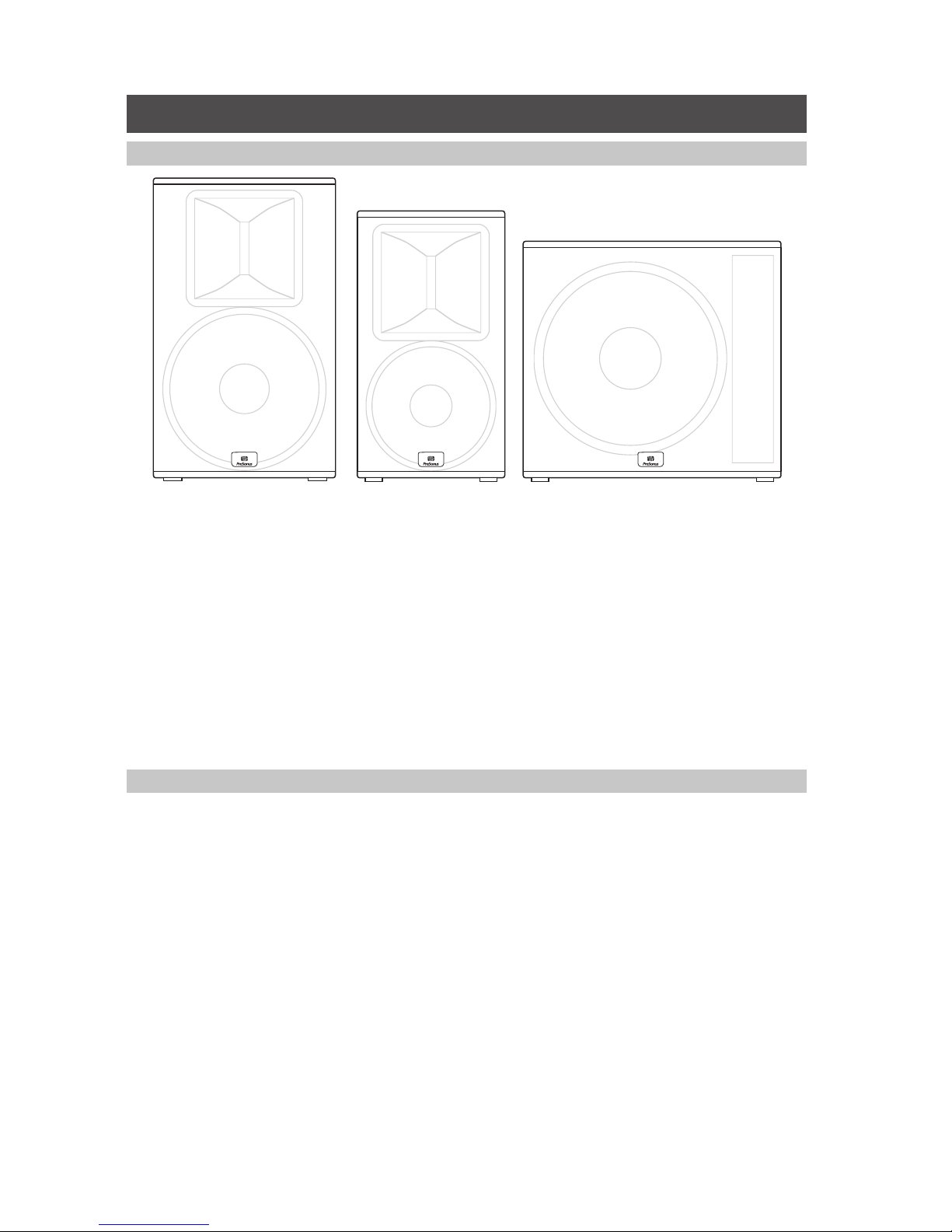
1.3 Summary of ULT-Series Loudspeaker Features
1.3.1 Full-range Models (ULT12 and ULT15)
• 12” / 15” Woofer with 2.5” Voice Coil
• 1.75” diaphragm compression driver
• Worx designed waveguide Pivot X110 Horn for precise coverage
• Ultrawide 110˚ horizontal dispersion
• Tight 50˚ vertical dispersion for farther throw
• 3 presets plus high pass filter
• Maximum SPL 135 / 136 dB peak
• 55 Hz to 18 kHz / 52 Hz to 18 kHz frequency response
• Multi-angle enclosure for mains or monitor wedge application
• 1300-watt Class D power (150 x 500W continuous)
• Onboard mixer with two combo XLR and ¼” inputs; direct line
input channel output; and single summed balanced output
• Defeatable front-panel LED
• Rugged, texture-painted birch enclosures
• XMAX Preamp
• Rotatable horn for horizontal mains use
• Tour-grade 16 gauge steel grilles
• Comfortable ergonomic handles
• 35 mm pole sockets with 6˚ downward tilt
• M10 rigging points for suspended installation
• Locking IEC connection
1.3.2 ULT18 Subwoofer
• 18” Woofer with 4” Voice Coil
• 7mm driver travel before over-excursion
• Extended Bass preset
• Polarity Invert
• Onboard fully Variable Low Pass filter lets you dial in upper frequency limit
• Maximum SPL 135 dB peak
• 35 Hz to 150 Hz (variable) frequency response
• 2000-watt Class D power (2 × 500 W continuous)
• Stereo Combo XLR and ¼” inputs with direct outputs
• Mono Mode sums both inputs to both outputs
• Defeatable front-panel LED
• Rugged, texture-painted birch enclosures
• Tour-grade 16 gauge steel grilles
• Comfortable ergonomic handles
• Locking IEC connection
1 Overview
1.4 What is in the Box
ULT-series
Owner’s Manual
3
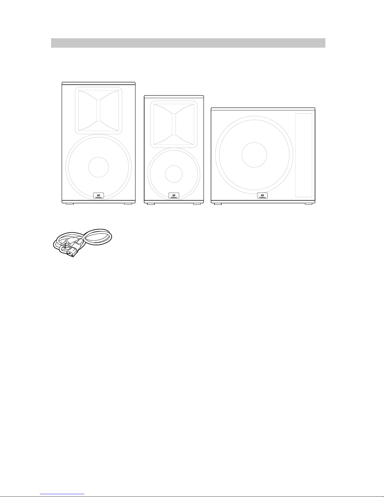
1.4 What is in the Box
In addition to this manual, your ULT package contains the following:
• (1) ULT12, ULT15, or ULT18 Loudspeaker
• (1) Locking IEC power cable
2 Getting Started
2.1 Level Setting Procedure (Full-Range)
ULT-series
Owner’s Manual
4
2 Getting Started
Before you begin, here are a few general rules of thumb:
• Always make sure your loudspeakers are powered off when making connections.
• Do not allow your inputs to clip. Watch the Clip LED on the back of your
loudspeaker. When this LED illuminates, it indicates that the analogto-digital converters are in danger of being overdriven. Overdriving
the converters will cause digital distortion, which sounds terrible.
• Your full-range loudspeaker provides attenuation control only for the speaker
and line levels. If you are not getting adequate volume with these controls
turned all the way up (0 dB), make sure that your mixer is properly gainstaged and that you are using enough loudspeakers for your application.
Your PA and studio equipment should be powered on in the following order:
1. Sound sources (keyboards, direct boxes, microphones,
etc.) connected to your mixer
2. Mixer
3. ULT-series Loudspeakers
When it’s time to power down, your system should be turned off in the reverse order.
Now that you know what not to do, let’s get some audio going! The following
level-setting tutorials cover best practices that can be applied to nearly every
application. The first tutorial covers level setting for the full-range models
only; the second tutorial describes proper level setting for a system that
includes one ULT18 subwoofer and two full-range ULT-series loudspeakers.
2.1 Level Setting Procedure (Full-Range)
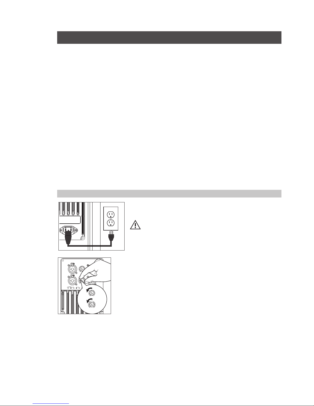
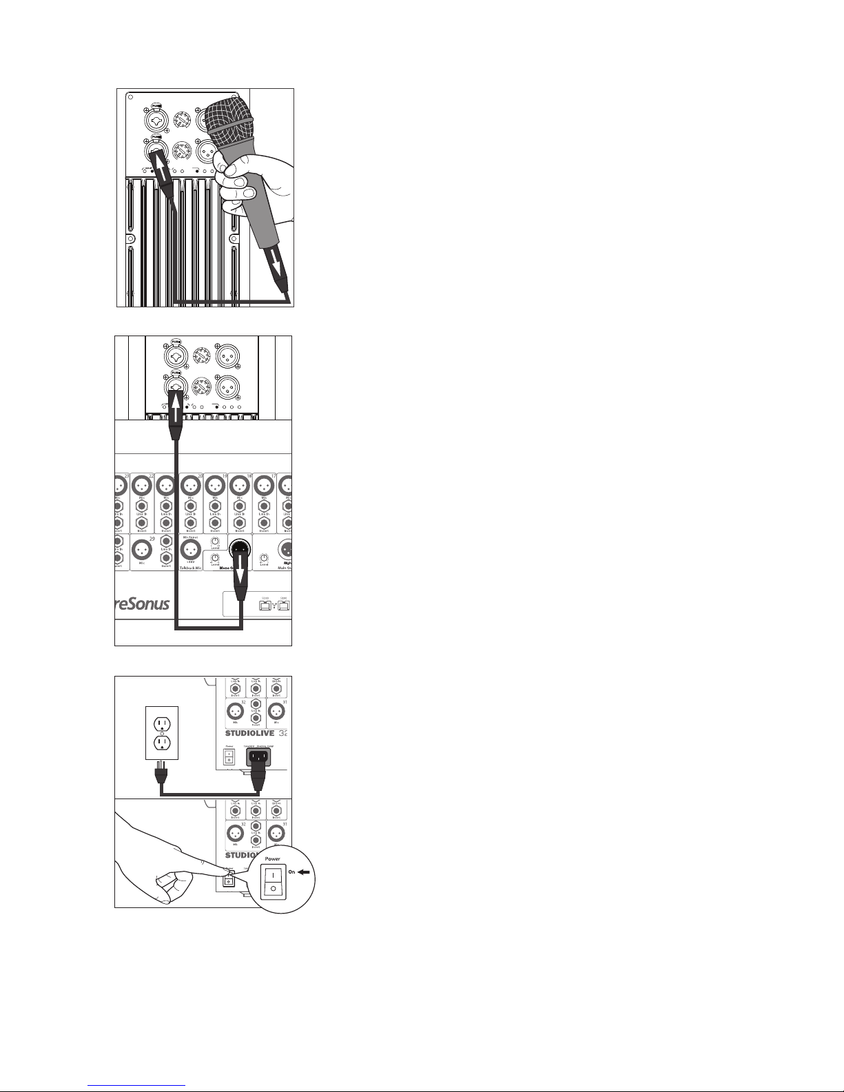
1. With the power switch in the Off position, connect the locking IEC plug to
the IEC socket connection on the back of the loudspeaker and plug it into
a grounded AC outlet or surge protector.
WARNING: While a locking IEC cable is ideal for permanent installation,
be careful that this cable cannot be tripped over in ground-stacked
applications, as this is a toppling risk.
2. Turn the level knobs fully counterclockwise, to the lowest position.
100-230V~, 50-60 Hz, 150W
DIRECT OUT
MIX OUT
LINE
HPF DJ FOHMON SIGNAL CLIP TEMP
MIC/LINE
LINE LEVEL
MIC / LINE
MIC/LINE
-15 +65
M
I
C
L
I
N
E
LINE LEVEL
MIC / LINE
-15 +65
M
I
C
L
I
N
E
2 Getting Started
2.1 Level Setting Procedure (Full-Range)
ULT-series
Owner’s Manual
5
3. If you’re using the ULT full-range loudspeaker as a mixer, connect
a microphone to the Mic input with a standard XLR cable.
4. Connect your line-level source (such as a PreSonus StudioLive
digital mixer) to the Line input. The Line input is a combo
connection that accepts a balanced ¼” TRS or XLR cable.
Power User Tip: If you are running a stereo system, connect the
Left output of your mixer to the Left loudspeaker’s line input, and
the Right output to the Right loudspeaker’s line input.
5. Power on your line-level source.
DIRECT OUT
MIX OUT
LINE
HPF DJ FOHMON SIGNAL CLIP TEMP
MIC/LINE
LINE LEVEL
MIC / LINE
-15 +65
M
I
C
L
I
N
E
DIRECT OUT
MIX OUT
LINE
HPF DJ FOHMON SIGNAL CLIP TEMP
MIC/LINE
LINE LEVEL
MIC / LINE
MIC/LINE
-15 +65
M
I
C
L
I
N
E
2 Getting Started
2.1 Level Setting Procedure (Full-Range)
ULT-series
Owner’s Manual
6
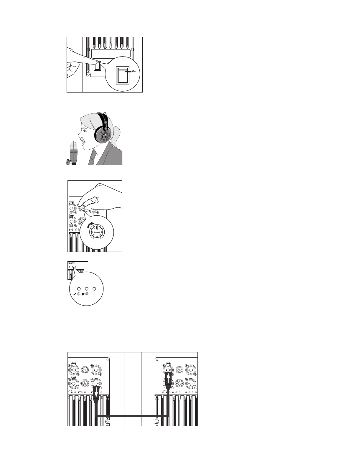
6. Power on your ULT-series loudspeaker.
7. While speaking into the microphone, use the Mic level knob to
adjust the microphone level. Be sure that you are not standing
directly in front of the loudspeaker while doing this, as doing so
could result in feedback. If you are not using the Mic input, it is
recommended that you leave this knob in the fully counter-clockwise
position so as not to introduce noise into your signal path.
8. With audio playing through your line-level source, turn the
Line level knob until you have achieved a comfortable listening
volume. If you are not using the Line input, it is recommended
that you leave this knob in the fully counterclockwise position
so as not to introduce noise into your signal path.
9. Both the Microphone and Line inputs should be set so that the
green Signal LED is illuminated most of the time, but the red Clip
LED illuminates only with the highest transient peaks or not at all.
10. If you are using the input mixer of one loudspeaker to
connect a microphone and a line-level source, or if you
are running a mono system, connect the Mix Out from the
loudspeaker to which your sources are connected to the line
input of the second loudspeaker and repeat steps 1-9.
POWER
On/O
100-230V~, 50-60 Hz, 150W
DIRECT OUT
MIX OUT
LINE
HPF DJ FOHMON SIGNAL CLIP TEMP
MIC/LINE
LINE LEVEL
MIC / LINE
-15 +65
M
I
C
L
I
N
E
LINE LEVEL
SIGNAL CLIP TEMP
SIGNAL CLIP TEMP
DIRECT OUT
MIX OUT
LINE
HPF DJ FOHMON SIGNAL CLIP TEMP
MIC/LINE
LINE LEVEL
MIC / LINE
MIC/LINE
-15 +65
M
I
C
L
I
N
E
DIRECT OUT
MIX OUT
LINE
HPF DJ FOHMON SIGNAL CLIP TEMP
MIC/LINE
LINE LEVEL
MIC / LINE
MIC/LINE
-15 +65
M
I
C
L
I
N
E

2 Getting Started
2.2 Level Setting Procedure (ULT18)
ULT-series
Owner’s Manual
7
2.2 Level Setting Procedure (ULT18)
1. With the power switch in the Off position, connect the locking IEC
plug to the IEC socket connection on the back of each loudspeaker
and plug it into a grounded AC outlet or surge protector.
2. Turn the level knobs on your full-range loudspeakers
fully counterclockwise to the lowest position.
3. Turn the Output level knob on your ULT18
counterclockwise to the lowest position.
4. Connect your line-level source (e.g., a StudioLive mixer) to the Line
inputs. This is a combo jack that accepts a balanced ¼” TRS or XLR plug.
If you are connecting a stereo source, the left side should be connected
to Input 1 and the right side should be connected to Input 2.
100-230V~, 50-60 Hz, 150W
DIRECT OUT
MIX OUT
LINE
HPF DJ FOHMON SIGNAL CLIP TEMP
MIC/LINE
LINE LEVEL
MIC / LINE
MIC/LINE
-15 +65
M
I
C
L
I
N
E
LINE LEVEL
MIC / LINE
-15 +65
M
I
C
L
I
N
E
MIC/LINE
OUTPUT 1
OUTPUT 2
INPUT 1
LOW PASS FILTER
OUTPUT LEVEL
60 Hz 80 Hz
100 Hz
INPUT 2
OUTPUT LEVEL
MIC/LINE
SIGNAL CLIP TEMP
OUTPUT 1
OUTPUT 2
INPUT 1
LOW PASS FILTER
OUTPUT LEVEL
60 Hz 80 Hz
100 Hz
INPUT 2
Natural Mono
0
 Loading...