

Page 1

UC Surface
UC Surface
Software Reference Manual
®
www.presonus.com
English
Page 2

Table of Contents
1 Introduction — 1
1.1 About This Manual — 1
2 Mix Controls — 3
2.1 Selecting Your Mix — 3
2.2 Copy Mix — 4
2.3 Input Channel Controls — 5
2.3.1 Channel Strip — 5
2.3.2 Channel Detail — 5
2.3.3 Channel Settings — 7
2.4 Mix Detail — 8
2.4.1 Aux and Matrix Mix Detail — 8
2.4.2 Subgroup Mix Detail — 9
2.5 Filter DCAs — 10
2.5.1 Creating, Editing, and Deleting
Filter DCAs — 11
2.5.2 Group Masters — 12
3 Fat Channel Controls — 13
3.1 Noise Gate — 13
3.1.1 Key Filter Sidechaining — 14
6 Presets — 23
6.1 Fat Channel Presets — 23
6.2 GEQ Presets — 24
6.3 FX Presets — 24
6.4 Preset Management — 25
7 Projects and Scenes — 26
7.1 Project and Scene Management
(StudioLive Series III) — 26
7.1.1 Import /Export — 27
7.2 Mix Scenes (StudioLive AI-series) — 28
7.2.1 Quick Scenes — 28
7.2.2 Scenes Library — 29
7.2.3 Scene Safe Edit — 29
8 Quick Panel Functions — 31
8.1 Talkback — 31
8.1.1 Talkback Destination — 31
8.1.2 Talkback Source
(StudioLive Rack Mixers) — 32
8.2 Mute Groups — 32
3.2 Compressor — 15
3.3 Equalizer — 16
3.4 Limiter — 17
4 Graphic EQ — 18
4.1 Enabling Smaart Analysis
(StudioLive AI-series only) — 19
4.1.1 Time-Frequency Spectrograph — 19
4.1.2 RTA — 20
4.2 Using the Smaart Spectrograph
to Ring Out Monitors — 20
4.3 Using the RTA While Mixing — 21
5 Adding Effects — 22
5.1 Editing Effects — 22
8.3 FX Mutes — 33
8.4 Fader Locate (StudioLive AI-series
Console Mixers only) — 33
9 The Settings Page — 34
9.1 Device Settings — 34
9.1.1 Device Permissions — 34
9.1.2 Configure Lockout (StudioLive AI
Console Mixers) — 37
9.1.3 Firmware — 37
9.1.4 System Settings — 38
9.2 Networking — 43
9.2.1 Wired Connection — 43
9.2.2 Stagebox Setup
(StudioLive Series III only) — 44
Page 3

9.2.3 EarMix Setup
(StudioLive Series III only) — 45
9.2.4 Wireless Connection
(StudioLive AI-series only) — 45
9.2.5 Cascading Mixers
(StudioLive RM/RML mixers) — 45
9.3 Backup — 46
9.4 Plug-ins (StudioLive Series III Mixers) — 46
9.5 User Profiles (StudioLive Series III Mixers) — 47
9.5.1 Default Administrator — 47
9.5.2 Creating a New Profile — 48
9.5.3 Edit User Permissions — 49
9.6 Digital Patching
(StudioLive Series III only) — 50
9.6.1 Input Source — 50
9.6.2 Input Patch — 51
9.6.3 Analog Sends — 51
9.6.4 AVB Sends — 52
9.6.5 USB Sends — 53
9.6.6 SD Sends — 53
9.6.7 AES — 54
9.7 Aux Routing (StudioLive AI-Series Mixers) — 54
9.8 Smaart System Check Wizards
(StudioLive AI-series only) — 55
9.8.1 Smaart Room Analysis Wizard — 56
9.8.2 Smaart System Delay Wizard — 58
9.8.3 Smaart Output Check Wizard — 61
9.8.4 Mic Position — 61
9.8.5 System Alignment Rules — 64
9.8.6 Using the Trace:
Spotting the Trend — 64
10 StudioLive Series III Rack Mixer
SD Recording — 68
10.1 Recording a New Capture Session — 68
10.2 Capture Screen — 69
10.3 Recording Status Indicators — 69
10.3.1 Status — 69
10.3.2 Recording Errors — 70
Page 4

1 Introduction
1.1 About This Manual
1 Introduction
UC Surface
Reference Manual
UC Surface is a powerful software application that provides control of
channel, subgroup, aux, and bus levels; Fat Channel parameters; aux
mixes; effects; and graphic EQs. It also provides a visual overview of your
StudioLive settings so that you can see, adjust, and organize them, as well
as a librarian, allowing you to easily manage your presets and scenes.
For StudioLive Series III and AI-series console mixers, UC Surface provides
bidirectional control that allows you to remote-control mixing functions
that are also available from their respective hardware control surfaces. Since
control is bidirectional, fader moves and parameter changes made on the
StudioLive mixing surface are reflected in UC Surface and vice versa.
For StudioLive Series III rackmount mixers and StudioLive AI-series RM
and RML mixers, UC Surface provides software-only control.
Power User Tip: The StudioLive CS18AI hardware controller for StudioLive AI-series RM/
RML mixers can be used in conjunction with UC Surface.
UC Surface will run on macOS, Windows, and Windows Touch computers, as well as
Android devices and iPads affording flexible control options for any mix situation.
To use UC Surface, you must do one of two things:
• Connect your StudioLive, computer, Android device, or iPad to the same
wireless network. This option will allow you to use any or all of these
devices to remote control your StudioLive mixer anywhere in the venue
• Connect and sync your StudioLive to your computer using your computer’s
host transport (USB, FireWire s800, or Thunderbolt). This option allows
you to use UC Surface while recording and playing back audio through
Capture™, Studio One®, or a third-party DAW of your choice.
Note: StudioLive AI-series mixers support the use of the Apple Thunderbolt to FireWire
adapter.
1.1 About This Manual
We suggest that you use this manual to familiarize yourself with UC Surface before
trying to use it to control your mixer. This guide assumes that you have followed
the networking procedures outlined in the Networking for StudioLive Remote
Control Guide. If you are using UC Surface on a Mac or Windows computer, you
must first install Universal Control. Please refer to the Using Your StudioLive as an
Audio Interface with Universal Control Reference Guide for installation instructions.
Throughout this manual, you will find Power User Tips. These
tips provide useful hints on how to best use UC Surface and take
advantage of unique workflow functions and features.
For the most part, StudioLive Series III and AI-series console and rack
mixers behave identically. Because of fundamental architectural
differences, some functionality is not available in every series and style
of mixer. When these differences occur, it will be noted as follows:
• StudioLive Series III mixers: All StudioLive Series III console and rack mixers.
• StudioLive AI-Series mixers: All StudioLive AI-series console and rack mixers.
• StudioLive Series III console mixers: StudioLive 64S,
StudioLive 32S, StudioLive 32SX, StudioLive 32SC,
StudioLive 32, StudioLive 24, and StudioLive 16
• StudioLive Series III rack mixers: StudioLive 16R,
StudioLive 24R, and StudioLive 32R
• StudioLive AI-Series console mixers: 16.4.2AI, 24.4.2AI, and 32.4.2AI
• StudioLive AI-Series RM/RML mixers: RM16AI,
RM32AI, RML16AI, and RML32AI
1
Page 5

1 Introduction
1.1 About This Manual
Hardware Guides:
Software Guides:
UC Surface
Reference Manual
This guide explains the functions and basic routing features of the audio interface
onboard your StudioLive mixer. The following companion guides are also available:
• StudioLive Series III Console Mixer Owner’s Manual. Use this reference
guide to understand all the hardware functions on your StudioLive
Series III console mixer (StudioLive 64S, StudioLive 32S, StudioLive 32SX,
StudioLive 32SC, StudioLive 32, StudioLive 24, and StudioLive 16).
• StudioLive Series III Rackmount Mixer Owner’s Manual. Use this reference
guide to understand all the hardware functions on your StudioLive Series
III rackmount mixer (StudioLive 32R, StudioLive 24R, StudioLive 16R).
• StudioLive AI-Series Console Mixer Owner’s Manual. Use this reference
guide to understand all the hardware functions on your StudioLive AI-Series
console mixer (StudioLive 32.4.2AI, StudioLive 24.4.2AI, StudioLive 16.4.2AI).
• StudioLive AI-Series Rackmount Mixer Owner’s Manual. Use this reference
guide to understand all the hardware functions on your StudioLive AISeries rackmount mixer (StudioLive RM/RML32, StudioLive RM/RML16).
• Capture 3 Reference Manual. Included with StudioLive mixers
is Capture, a digital-audio multitrack-recording application
designed to make recording quick and easy.
• Networking for StudioLive Remote Control. This guide will
assist you in creating a LAN network to remote control your
StudioLive from a computer, tablet, or mobile device.
• QMix-UC Reference Manual. This guide describes the features and functions
of QMix-UC with every StudioLive mixer model. QMix-UC lets up to 16 users
remotely control the Aux Mixes on your StudioLive using their smartphone.
• Studio One Integration Reference Manual. Studio One Artist is
included with every StudioLive mixer. In addition to being a powerful
DAW, Studio One provides unique routing and integration features.
This manual will help you get the most from your StudioLive
mixer when used with Studio One or Studio One Artist.
• Using Your StudioLive as an Audio Interface with Universal Control
Reference Guide. This guide describes the features and functions
Universal Control as well as how to use your StudioLive mixer as
an audio interface with your favorite DAW application.
Additional Resources:
• StudioLive Series III AVB Networking Guide. This manual covers advanced
AVB audio networking configuration for the StudioLive Series III mixers.
• StudioLive Series III HUI for ProTools DAW Control Addendum. StudioLive
Series III console mixers can control Avid ProTools® using HUI emulation.
• StudioLive Series III MCU for Logic DAW Control Addendum. StudioLive Series
III console mixers can control Apple Logic® using Mackie Control Universal
• StudioLive Series III Stage box Mode Addendum. The StudioLive Series III
rackmount mixers can be used as advanced stageboxes for StudioLive Series III
console mixers.
• StudioLive Series III Studio One DAW Control Addendum. StudioLive Series
III console mixers can be used to control Studio One and Studio One Artist.
2
Page 6
2 Mix Controls
2.1 Selecting Your Mix
2 Mix Controls
2.1 Selecting Your Mix
UC Surface
Reference Manual
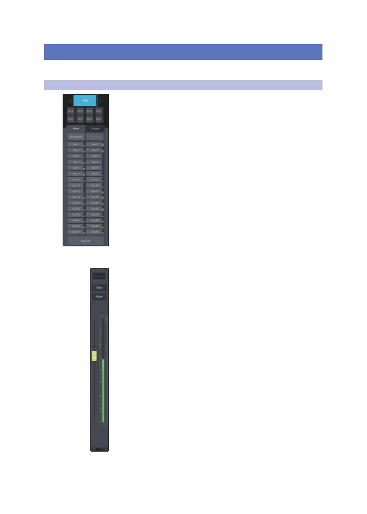
UC Surface provides a single window interface that
allows you to quickly view every mix.
The Mix Select buttons allow you to choose the mix you’d like to control (Auxes,
Mains, Subgroups). In addition, UC Surface provides a mix for each of the effects
buses. The returns for these effects are available in each mix to customize the
amount of reverb and delay.
Flex Fader
The fader immediately to the left of the Mix Select buttons controls the output level
of the currently selected mix.
3
Page 7

2 Mix Controls
2.2 Copy Mix
Main Fader
2.2 Copy Mix
UC Surface
Reference Manual
The fader(s) to the right of the Mix Select buttons always control(s) the Main mix
level.
• StudioLive 64S. When connected to a StudioLive 64S, three faders will
be visible. The Mono and Main faders control the output level of their
respective buses, while the Master fader is a grouped level control for both.
• StudioLive AI-series RM/RML. When connected to StudioLive AI-series RM and
RML mixers, a mono bus fader will also be visible.
Copying the current mix allows you to quickly set up multiple
mixes based on the settings you’ve already completed.
1. To copy a mix to any other mix, press the Copy Mix button.
2. Click on the desired destination mix(es).
3. Click Paste to paste the mix or click Cancel to stop the operation.
4
Page 8
2 Mix Controls
1
2
3
4
5
6
7
8
9
10
2.3 Input Channel Controls
2.3 Input Channel Controls
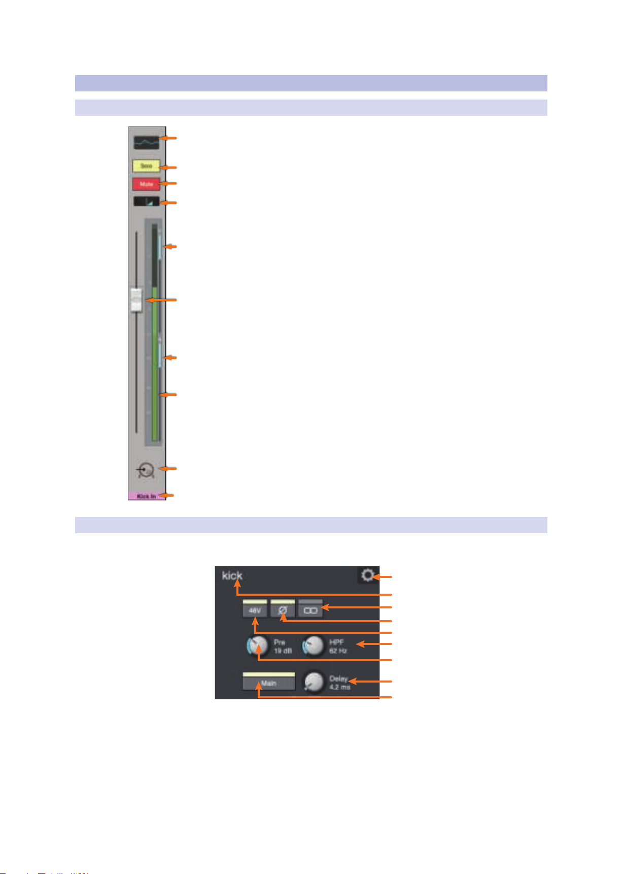
2.3.1 Channel Strip
1. Fat Channel Select. Opens the Fat Channel controls for the channel/mix. This
microview displays an overview of the EQ curve you set in the Fat Channel. See
Section 3 for more information about the Fat Channel section and its functions.
2. Solo Button. Turns soloing on and off.
3. Mute Button. Turns muting on and off.
4. Pan Controls. The Pan control sets the channel’s relative position in the
left/right stereo mix. When a pair of channels is stereo linked, the Pan
control sets the spread of the channels in the left/right stereo mix.
5. Compressor Gain Reduction Meter. This meter displays the amount
of gain reduction being applied by the current compressor setting.
Note: This meter is not available for StudioLive AI-series console mixers.
6. Channel Fader. Controls the Overall Level of the
Channel. Unity gain (0 dB) is denoted by a “U.”
UC Surface
Reference Manual
7. Gate Gain Reduction Meter. This meter displays the amount of
gain reduction being applied by the current gate setting.
Note: This meter is not available for StudioLive AI-series console mixers.
8. Level Meter. Displays the prefader level of each channel.
9. Channel Icon. Icons can be added to each channel to provide a quick
visual cue of which instrument is associated with which channel.
This is set from the Channel Settings window. See Section 2.3.3.
10. Channel Name and Color. Each channel can be given a custom name and
custom color for its Select button. This is set from the Channel Settings window.
See Section 2.3.3.
2.3.2 Channel Detail
When an input channel is selected, the following controls
will be available at the far left of the Fat Channel:
1
2
3
4
5
6
7
8
9
1. Channel Settings. Opens Channel Settings view. See Section 2.3.3 for details.
2. Channel Name. To give each channel a custom name, simply
click on the default name to open a text field.
3. Phantom Power Enables/disables phantom power
for the currently selected channel.
5
Page 9

2 Mix Controls
2.3 Input Channel Controls
4. Polarity. This button will illuminate when polarity
5. Link. Enables/disables stereo link.
6. High-Pass Filter. Sets the High-Pass Filter Frequency Threshold for the Selected
UC Surface
Reference Manual
is inverted on the current channel.
Power User Tip: The Polarity control inverts the polarity of the selected channel’s
preamp signal by 180°. The Polarity button can be used to correct audio signals that
are out of phase relative to each other, which causes frequency cancellation and
reinforcement. When recording with more than one open microphone, you may
need to invert the polarity to combat phase cancellation between microphones.
When a pair of channels is stereo linked, a toggle control is provided to the left
of the Channel Settings button so that you can toggle between the left and right
channel to access preamp controls for each.
Channel or Output Bus. The filter’s threshold can be set from 24 Hz to 1 kHz.
When the meter is set to its lowest point, the filter is off. The high-pass filter is
available on all input channels and on auxiliary and FX output buses only.
Power User Tip: A high-pass filter attenuates all frequencies below the set threshold.
Use the Fat Channel high-pass filter to remove unwanted low frequencies from your
source signal, rather than trying to EQ them out.
7. Mic Preamp Trim. A trim control is provided for all input channels
to adjust the gain of your digitally controlled XMAX preamps.
Note: This control is not available for StudioLive AI-series console mixers as these
mixers are not equipped with digitally recallable mic preamps.
8. Input Delay (StudioLive Series III mixers only). Sets the alignment
delay for the currently selected channel. For more information on using
an Input Delay, please review the StudioLive Series III Owners Manual.
9. Main Bus Assign. Use this button to assign the current channel
to the main bus. Additional bus controls are as follows:
• StudioLive 64S: Main Mono/Center
• StudioLive Series III mixers (32-channel models): Main Mix, Subgroups A-D
• StudioLive AI-series consoles: Main Mix, Subgroups 1-4
• StudioLive AI-series RM/RML mixers: Main Mix, Mono
Note: StudioLive RM-series and Series III mixers offer flexible mix functionality that
allows you to make any FlexMix function as an aux bus or subgroup. Please see
Section 2.4.2 for channel routing to a FlexMix subgroup.
6
Page 10
2 Mix Controls
2
1
3
4
5
6
7
2.3 Input Channel Controls
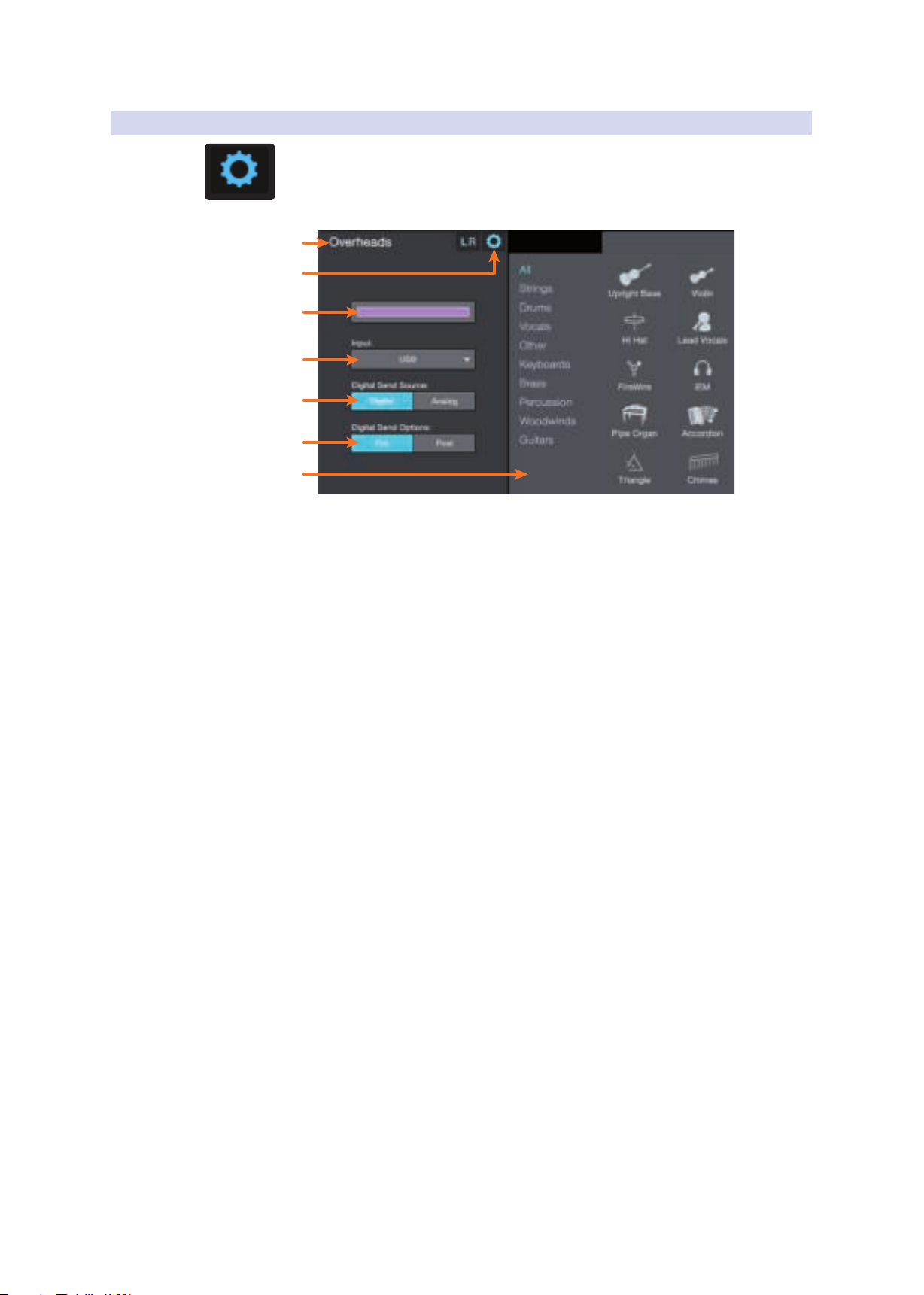
2.3.3 Channel Settings
When a channel is selected, the Settings icon for that channel is visible in the left side
of the Fat Channel.
After pressing the Settings icon, the following controls will
be available at the far left of the Fat Channel:
UC Surface
Reference Manual
1. Channel Name. Click or touch to edit the channel name.
2. Exit. Click or touch to exit the Channel Settings view.
3. Color. Click or touch to set a custom color for the current channel.
Power User Tip: Creating colors for different channel types is a great way to visually
group channels, allowing you to quickly identify a channel by type (drums, guitars,
vocals, etc.). You can choose to color the entire channel strip or just the channel
name. See Section 9.1.4 for details.
4. Input Source. This drop-down menu allows you to select the source
for the current channel. The following options are available:
• StudioLive Series III: Analog, Network, USB, or SD Card
• StudioLive AI consoles: Analog or FireWire
• StudioLive RM-series: Analog, FireWire, or Network
5. Set Pre- / Post-Processing Send. Select Pre- or Post-Fat
Channel processing for digital sends for each channel.
6. Digital Send Source (StudioLive Series III only). This allows you
to select source input of the digital send for each channel.
7. Apply a Channel Type and Icon. Clicking on the Channel Type
button lets you apply a category and icon for your channel.
Channels in the same category will automatically be placed into
the same Filter DCA Group (See Section 2.6 for details).
7
Page 11
2 Mix Controls
2.4 Mix Detail
2.4 Mix Detail
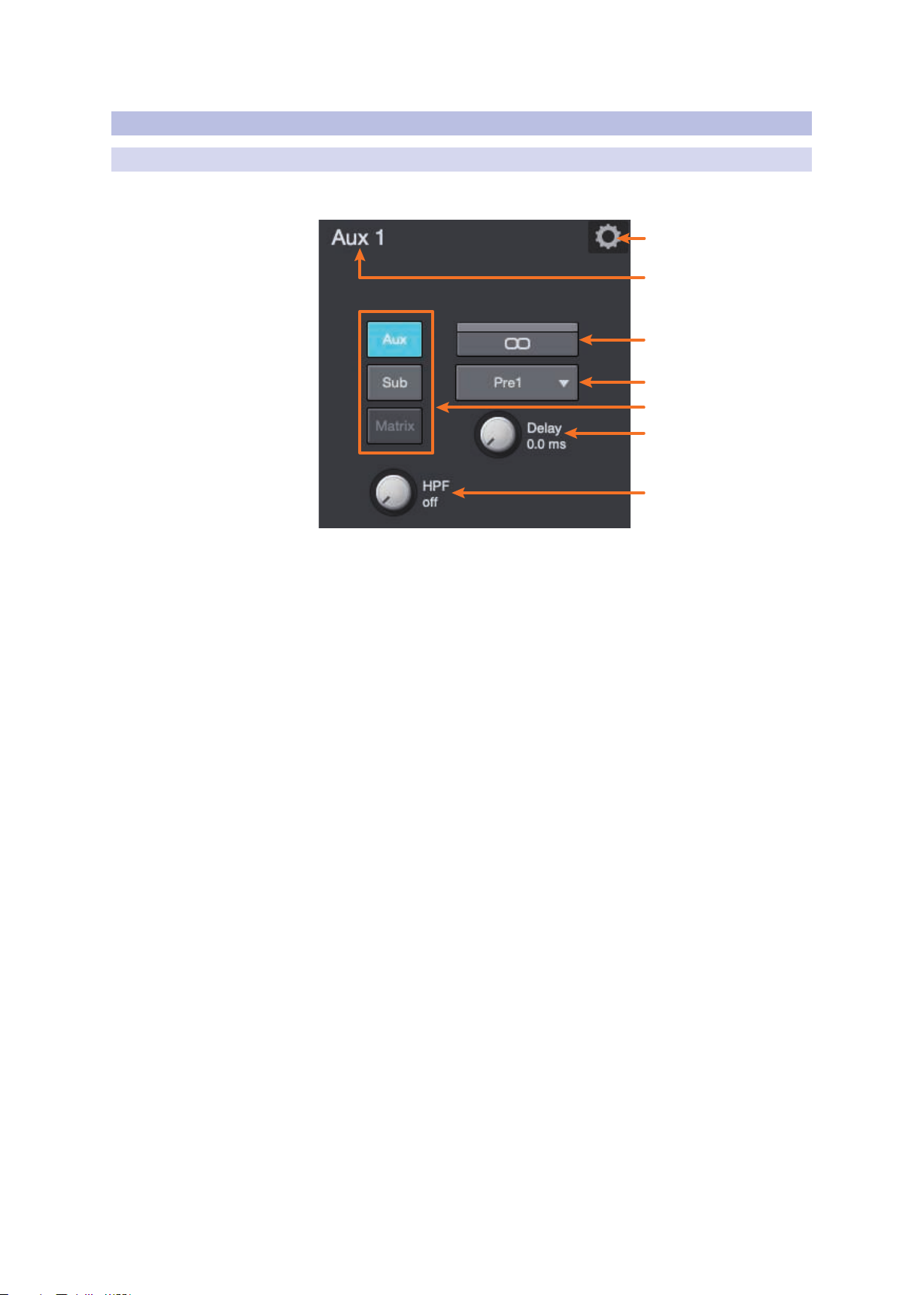
2.4.1 Aux and Matrix Mix Detail
When a mix is selected, the following controls will be
available at the far left of the Fat Channel:
UC Surface
Reference Manual
1
2
3
4
5
6
7
1. Mix Settings. Opens Mix Settings View. See Section 2.5 for details.
2. Mix Name. To give each mix a custom name, simply
click on the default name to open a text field.
3. Stereo Link. Creates a stereo bus with the adjacent FlexMix.
4. Aux Send Position. By default, all aux buses are set to Pre 1. This places the
send of every input channel to each aux bus before the fader, limiter, EQ,
and compressor, but after the Polarity switch, high-pass filter, and gate.
The four internal effects buses are set to Pre 2 by default, which routes each
of the input channels after all Fat Channel dynamics and EQ but prefader.
From this menu, you can choose between three
send positions for each Aux and FX mix:
• Pre 1: Sends each channel to the aux bus after the
polarity invert, high-pass filter, and gate.
• Pre 2: Sends each channel to the aux bus after all Fat
Channel processing (polarity invert, high-pass filter, gate,
compressor, EQ, and limiter) but before the fader.
• Post: Sends each channel to the aux bus after all Fat
Channel processing (polarity invert, high-pass filter, gate,
compressor, EQ, and limiter) and after the fader.
Power User Tip: Use the Pre 2 position for headphone and in-ear mixes to give
your performers a polished “studio” sound. This setting should be avoided for
floor wedges, as compression can cause feedback problems.
5. Bus Type (Series III and RM-series mixers only). StudioLive Series III and
AI-series RM/RML mixers’ feature FlexMixes that can be configured as aux mixes,
subgroups, or matrix mixes (Series III only). Use these buttons to select the bus
type. See Section 2.4.2 for information on routing channels to FlexMix subgroups.
6. Output Delay (StudioLive Series III only). Sets the alignment
delay for the current FlexMix. For more information on using output
delays, please review the StudioLive Series III Owners Manual.
8
Page 12
2 Mix Controls
8
2.4 Mix Detail
7. High-Pass Filter. Sets the High-Pass Filter Frequency Threshold for the Selected
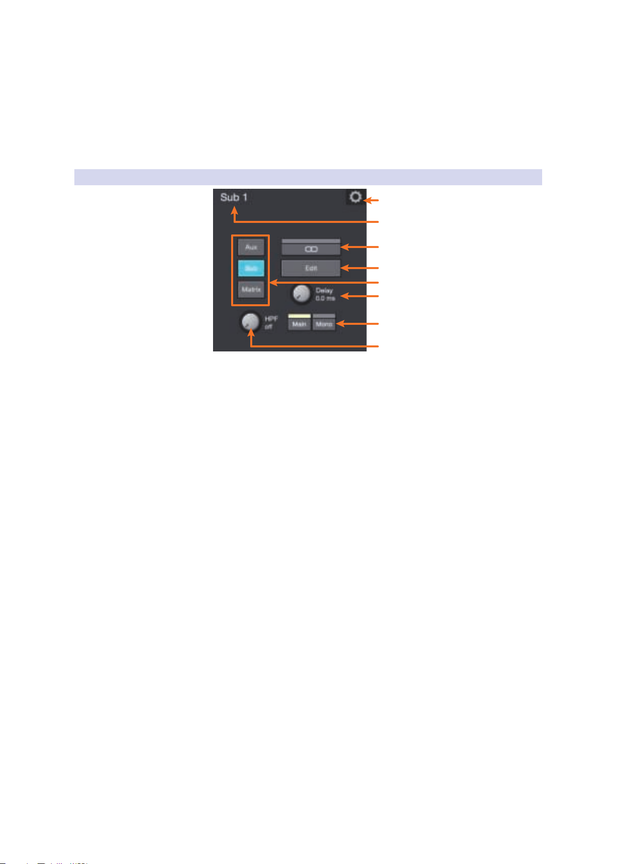
2.4.2 Subgroup Mix Detail
UC Surface
Reference Manual
Channel or Output Bus. The filter’s threshold can be set from 24 Hz to 1 kHz.
When the meter is set to its lowest point, the filter is off. The high-pass filter is
available on all input channels and on auxiliary and FX output buses only.
Power User Tip: A high-pass filter attenuates all frequencies below the set threshold.
Use the Fat Channel high-pass filter to remove unwanted low frequencies from your
source signal, rather than trying to EQ them out
1
2
3
4
5
6
7
1. Mix Settings. Opens Mix Settings view. See Section 2.5 for details.
2. Mix Name. Click or tap on the default name to open
a text field to customize the mix name.
3. Stereo Link. Click or tap to create a stereo subgroup with the adjacent FlexMix.
4. Subgroup Edit. Click or tap to add or remove channels from the subgroup.
5. Bus Type (Series III and RM-series mixers only). StudioLive
Series III and AI-series RM/RML mixers’ feature FlexMixes that
can be configured as aux mixes, subgroups, or matrix mixes
(Series III only). Use these buttons to select the bus type.
6. Output Delay (StudioLive Series III only). Sets the alignment
delay for the current FlexMix. For more information on using output
delays, please review the StudioLive Series III Owners Manual.
7. Route to Main. Click or tap to route the subgroup to the Main bus.
StudioLive 64S users will also find a Mono assign for the Mono/Center bus.
8. High-Pass Filter. Sets the High-Pass Filter Frequency Threshold for the Selected
Channel or Output Bus. The filter’s threshold can be set from 24 Hz to 1 kHz.
When the meter is set to its lowest point, the filter is off. The high-pass filter is
available on all input channels and on auxiliary and FX output buses only.
Power User Tip: A high-pass filter attenuates all frequencies below the set threshold.
Use the Fat Channel high-pass filter to remove unwanted low frequencies from your
source signal, rather than trying to EQ them out
9
Page 13
2 Mix Controls
2.5 Filter DCAs
UC Surface
Reference Manual
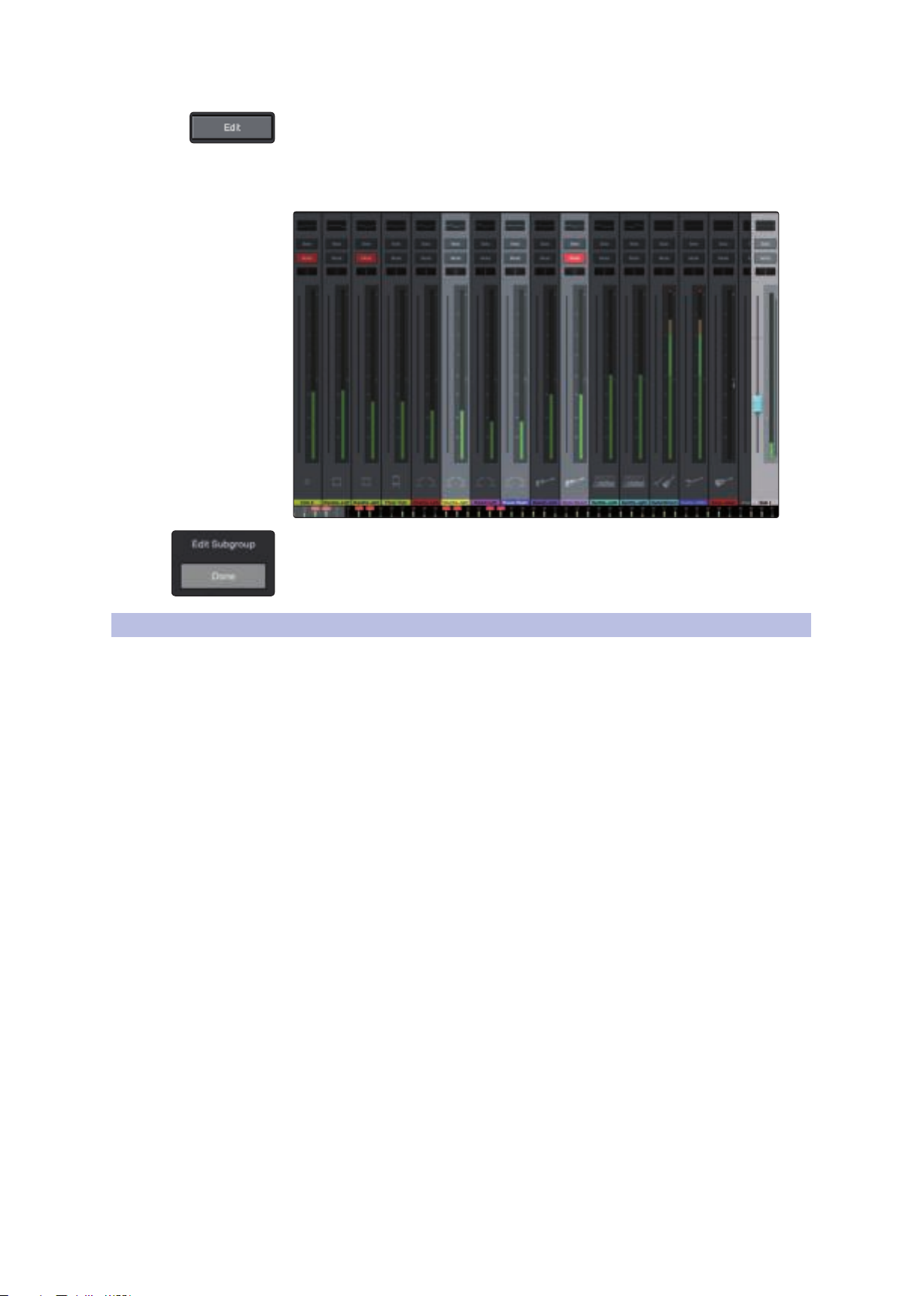
When a FlexMix subgroup is selected, you will find the Edit button in the Mix Detail
area of the Fat Channel. Clicking this button will allow you to route input channels to
this subgroup.
Click on the channels you would like assigned to the subgroup. The channel will
highlight as it is selected, indicating that it has been routed to the subgroup.
2.5 Filter DCAs
Click the Done button when you’ve assigned the desired channels
Professional mixing consoles have addressed the problem of managing complex
mixes with population groups that reduce the channels you’re viewing at
one time and DCAs that control the overall level of a group of channels.
We’ve combined the best aspects of these solutions with Filter DCAs. A Filter DCA
can contain any combination of the available input channels and effects returns,
and you can create up to 24 Filter DCA groups as you need. You can even include
the same channel in multiple Filter DCAs so you can manage mixes in multiple
ways. Each group is given a master level control so you can control the overall
level of the group while maintaining each channel’s relative balance in the mix.
In this way, for example, you can create a single fader to control every drum in a
monitor mix and maintain the relative level of the drum mix that you created.
Once selected, a Filter DCA group stays active until exited regardless of which mix is
selected. This allows you to adjust the group independently across different mixes.
You can also flip between groups on the fly to change the view of a selected mix.
Note: Filter DCAs are not available for StudioLive AI-series console mixers.
10
Page 14
2 Mix Controls
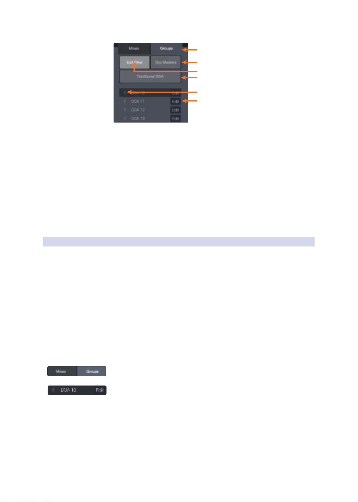
4
1
3
2
6
5
2.5 Filter DCAs
UC Surface
Reference Manual
1. Groups Tab. Opens Filter DCA list.
2. Group Masters. Displays only the Master fader for every Filter DCA.
3. Exit Filter. The Exit Filter button will be visible as soon as a Filter DCA is selected.
In this way, you can exit the Filter DCA and view all the channels in your mix.
4. Traditional DCA. When controlling the master level a DCA Group, the
faders for the channels assigned to that group will move to more accurately
provide a visual indication of the actual level of each channel in the group.
This feature can be defeated by enabling “Traditional DCA” mode.
5. Reorder. Moves Filter DCA up or down in the list.
6. Edit Filter DCA. Opens Edit mode options (Rename,
Add/Remove Channels, Delete).
2.5.1 Creating, Editing, and Deleting Filter DCAs
There are two ways a Filter DCA group can be created.
• Auto-created Filter DCA Groups. When a channel is assigned a Channel
Type, UC Surface automatically creates a Filter DCA group based on that
information. For example, when you define a channel type within in the
Drums category for any channel in your mix, a Drums group will be added
to the Filter DCAs. Auto Filter DCA groups are displayed in the bottom part
the Filter DCA group list with a “~” in front of their names. These Filter DCAs
can be hidden from the System Preferences page. See Section 8.1.4.
• User-created Filter DCA Groups. You can create new Filter DCA groups
from scratch or by editing an existing Auto Filter DCA group. Any number
of channels can be added to a group, and you can create as many groups
as you wish. User-created groups are always shown at the top of the
Filter DCA group list above the automatically generated groups.
To create a new Filter DCA group:
1. Click/tap the Group tab in the Mixer Selection area.
2. Select the Filter DCA you would like use and then click/tap the Edit button to
enter Edit mode. From here you can add and remove channels as necessary.
11
Page 15
2 Mix Controls
2.5 Filter DCAs
UC Surface
Reference Manual
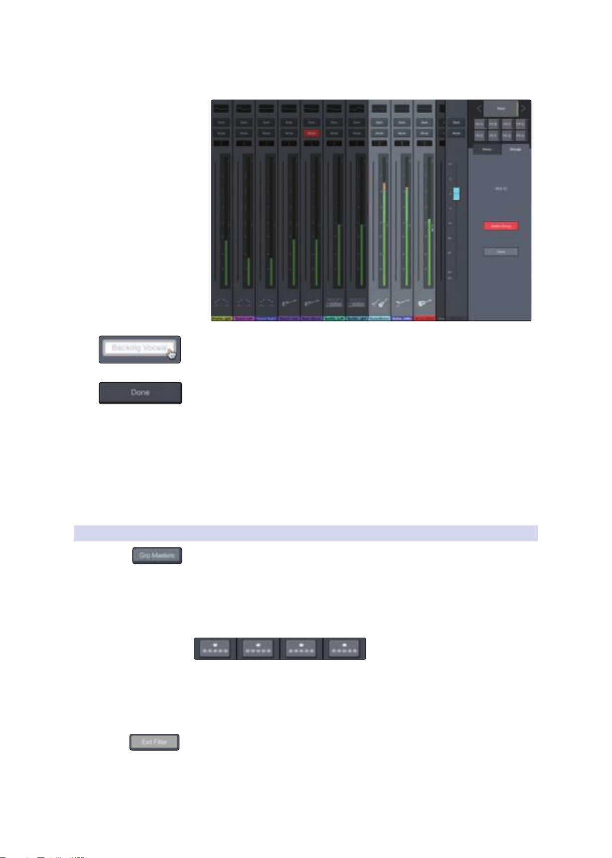
3. You’ll notice all the channel strips in the mixer are darkened. Click
or tap on the channels you’d like to add to your Filter DCA.
4. You can customize the name of your new Filter DCA by clicking or tapping on
the default name (New Filter DCA).
5. Click or tap on the Done button when you are finished editing.
Editing and Deleting Filter DCAs
Filter DCAs can be edited or deleted at any time by clicking
or tapping the Edit (#6) button in the list view.
Managing Filter DCAs
You can reorder the Filter DCA list by clicking or tapping on the Reorder
(#5) button to the left of it and then clicking or tapping the Reorder
button next to the position to which you would like it to move.
2.5.2 Group Masters
The Group Masters button allows you to view only the Master fader for every Filter
DCA. Soloing or muting a group master will solo or mute all the channels in its group.
Power User Tip: The Group Masters view can be a great way for musicians to manage
their own mix. For example, they can manage the drums as an entire group, their vocal
mix, the overall band mix, etc., rather than managing individual channels.
Spill Group
While the Group Masters are active, you will see the Spill Group button
on top of each master fader. Clicking or tapping this button will spill the
group, allowing you to see all the channels in the group and adjust their
level, pan, or Fat Channel settings. While in Spill Group, the Flex fader will
control the master level of the group regardless of which mix you select.
To close this view, click or tap on the Exit Filter button.
12
Page 16
3 Fat Channel Controls
1
2
3
4
5
6
7
8
9
10
11
12
13
3.1 Noise Gate
3 Fat Channel Controls
Every input and bus on your StudioLive mixer is equipped with Fat Channel
dynamics processing and filtering. The revolutionary Fat Channel is the heart of
the StudioLive. The Fat Channel makes dynamics, routing, and panning for every
input and output on the StudioLive available at the touch of a Select button.
The Fat Channel’s processing section consists of five parts: High-Pass Filter,
Noise Gate, Compressor, Limiter, and parametric EQ. Each can be turned on
or off and controlled separately. This processing is global across all mixes.
The signal flows as follows:
Hi-Pass LimiterEQØ Noise Gate Compressor
Note: For StudioLive AI-series mixers, when HD mode (88.2 or 96 kHz sample rate) is
active, Fat Channel processing is disabled on all output buses.
StudioLive Series III mixers allow you to swap the positions of
the Compressor and EQ stages of the Fat Channel.
Power User Tip: Placing the compressor before the EQ allows you to make dramatic
changes to the EQ settings without needing to alter the compressor setting. However, if
you place the EQ before the compressor, you can better control different frequencies,
achieving a more natural response.
UC Surface
Reference Manual
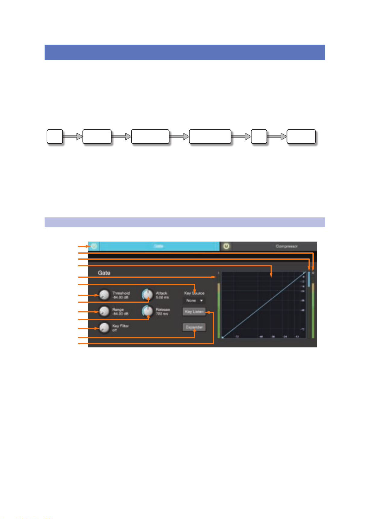
3.1 Noise Gate
To view the controls for the Noise Gate, click on the Gate tab.
Note: The Noise Gate is available on the input channels only.
1. Gate On/Off Button. Engages/disengages the gate for the selected channel.
2. Output Meter (Series III only). Displays the post-Gate output signal.
3. Gain Reduction Meter (Series III only). Displays the amount
of gain reduction being applied to the signal by the gate.
4. Gate Graph. This graph shows the point at which the gate
threshold affects the signal. You can either use this graph to adjust
the threshold or the dedicated threshold control (#3).
5. Input Meter (Series III only). Displays the input signal to the Gate.
6. Key Source (Series III only). Sets the trigger source for the gate’s Key Filter. See
the StudioLive Series III Owner’s Manual for more information on sidechaining.
7. Gate Threshold. Sets the level at which the gate opens. Essentially, all
signals above the threshold setting are passed through unaffected, whereas
13
Page 17

3 Fat Channel Controls
3.1 Noise Gate
8. Gate Attack. Sets the rate at which the gate opens on the selected
9. Gate Range. Sets the amount of gain reduction that the gate
10. Gate Release. Sets the rate at which the gate for the selected channel
UC Surface
Reference Manual
signals below the threshold setting are reduced in level by the amount
set by the range control. You can set the threshold from 0 to -56 dB.
channel or output. A fast attack rate is crucial for percussive instruments.
Slow-rising signals such as vocals and bass guitar require a slower
attack; with these signals, a faster attack can cause an audible click. All
gates have the ability to click when opening but a properly set gate
will never click. You can set the attack time from 0.2 to 150 ms.
will produce. The range can be set from 0 to -86 dB.
Note: Range control is not available when using the Expander.
closes. Gate-release times should typically be set so that the natural decay
of the instrument or vocal being gated is not affected. Shorter release
times help to clean up the noise in a signal but may cause “chattering“
with percussive instruments. Longer release times usually eliminate
chattering and should be set by listening carefully for the most natural
release of the signal. The release time can be set from 0.05 to 2 seconds.
11. Gate Key Filter. Sets the frequency at which the gate will open. Setting a
specific frequency, in addition to a specific decibel level, provides more sonic
shaping. The Key Filter can be triggered by the selected channel or bus’s
signal or by side-chaining a channel and using its signal as the source.
Power User Tip: A properly set key filter on a gate can greatly improve the overall
sound quality of a mix. For example, if you are inserting a gate on a snare-drum mic,
you may get enough bleed from the kick drum to open the gate. This is where a key
filter can come in handy. By setting the key filter to remove some of those low
frequencies, the gate won’t be as apt to open for the kick drum.
12. Gate Expander Button. StudioLive mixers allow you to choose
between an expander and a noise gate for each channel or
output. By default, the Expander button will be enabled.
Power User Tip: In practice, expanders and noise gates are used almost identically.
The main difference is that an expander is smoother and more gradual, so that it is
easier to set the attack and release times correctly.
13. Key Listen. Enable to listen to the signal being used to trigger the gate.
3.1.1 Key Filter Sidechaining
As previously mentioned, the key filter can be sidechained to another channel.
Sidechaining has many uses. You can use a sidechained key filter to tighten up
a rhythm section by sidechaining the kick drum channel to the bass channel
and setting the gate to open at the frequency of the kick drum. This, combined
with a fast attack and release, will make your rhythm section more cohesive.
Increase the release time to loosen the feel. Please note that while sidechaining
the kick drum to the bass channel can tighten up a good rhythm section and
make them sound even better, it will not correct timing issues and will actually
exaggerate them if your bass player and drummer aren’t in the pocket.
Another great use for a sidechain is as an effect in electronic music production. Try
sidechaining a drum loop to a sustained source, like pads or strings. By doing this,
every time a drum hit triggers the key filter, your sustained source will be heard.
Between hits, this source will be silenced. Playing with the attack and release will
transform this effect from a rhythmic pulse all the way to a chopped-up stutter.
14
Page 18
3 Fat Channel Controls
1
6
4
8
15
14
5
7
9
11
10
12
13
2
3
3.2 Compressor
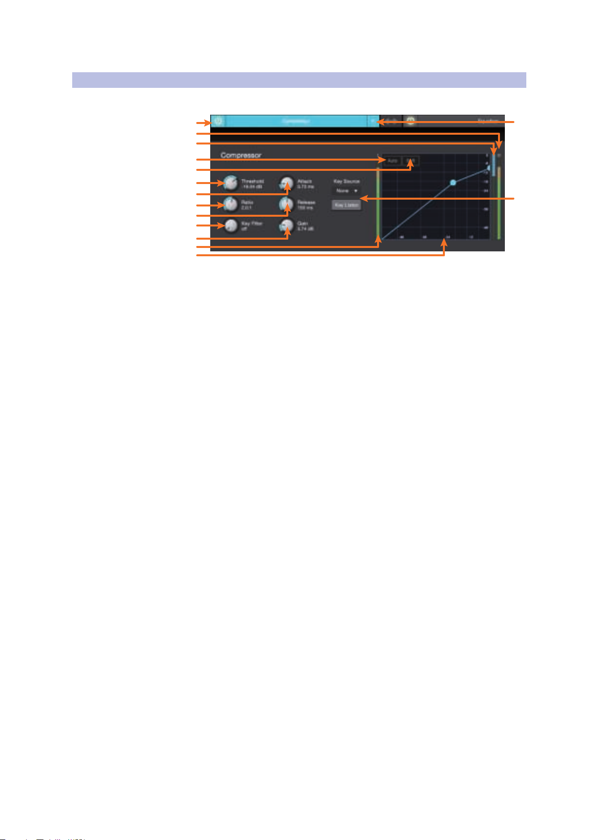
3.2 Compressor
To view the controls for the Compressor, click on the Compressor tab.
1. Compressor On/Off. Turns the Compressor On and Off for the selected channel.
2. Output Meter (Series III only). Displays the post-Compressor output signal.
3. Gain Reduction Meter (Series III only). Displays the amount of
UC Surface
Reference Manual
gain reduction being applied to the signal by the compressor.
4. Auto Mode Button. When Auto mode is active, the Attack and Release
controls become inoperative, and a preprogrammed attack and release
curve is used. In this mode, the attack is set to 10 ms, and the release is set to
150 ms. All other compressor parameters can still be adjusted manually.
5. Soft Knee Toggle Button. Engages Soft-Knee Compression. In normal
operating mode, the compressor is set for hard-knee compression, meaning
that the gain reduction applied to the signal occurs as soon as the signal
exceeds the threshold. When the Soft Knee button is engaged, the onset of
gain reduction occurs gradually after the signal has exceeded the threshold.
6. Compressor Threshold. Sets the compressor threshold for the selected channel
or output bus. When the signal’s amplitude (level) exceeds the threshold
setting, the compressor engages. The threshold can be set from -56 to 0 dB.
7. Compressor Attack. Sets the compressor attack for the selected channel. Attack
sets the speed at which the compressor acts on the input signal. A slow attack
time (fully clockwise) allows the beginning component of a signal (commonly
referred to as the initial transient) to pass through, uncompressed, whereas a fast
attack time (fully counterclockwise) triggers compression immediately when a
signal exceeds the threshold. You can set the attack from 0.2 to 150 milliseconds.
8. Ratio. Sets the compression ratio (or slope) for the selected channel or output
bus. The ratio sets the compression slope, which is a function of the output
level versus the input level. For example, if you have the ratio set to 2:1, any
signal levels above the threshold setting will be compressed at a ratio of
2:1. This means that for every 2 dB of level increase above the threshold, the
compressor’s output will only increase 1 dB. The ratio can be set from 1:1 to 14:1.
9. Compressor Release. Sets the compressor release for the selected channel
or output bus. Release sets the length of time the compressor takes to return
the gain reduction back to zero (no gain reduction) after crossing below the
compression threshold. Release can be set from 40 to 1,000 milliseconds.
Power User Tip: Very short release times can produce a choppy or “jittery” sound,
especially when compressing instruments that have a lot of low-frequency
components, such as bass guitar. Very long release times can result in an
overcompressed, or “squashed,” sound. All ranges of release can be useful, however,
and you should experiment to become familiar with different sonic possibilities.
15
Page 19

3 Fat Channel Controls
1
2
3
4
5
6
7
8 9 10
11
12
13
14
15
3.3 Equalizer
10. Key Filter. Sets the frequency at which the compressor will engage.
11. Compressor Makeup Gain. Sets the amount of makeup gain for the selected
12. Input Meter (Series III only). Displays the input signal to the compressor.
13. Compressor Graph. This graph shows the point at which the
14. Key Source (Series III only) and Key Listen. Sets the Key
15. Compressor Type (Series III only). This drop-down menu allows
3.3 Equalizer
UC Surface
Reference Manual
The compressor will still process the entire frequency range, but
it is only engaged when the specified frequency is present.
channel or output bus. When compressing a signal, gain reduction usually
results in an overall attenuation of level. The gain control allows you to restore
this loss in level and readjust the volume to the pre-compression level (if
desired). You can adjust Makeup Gain from 0 dB (no gain adjustment) to +28 dB.
compressor threshold affects the signal. You can use this graph to
adjust the threshold or use the dedicated Threshold control (#4).
Source for the Compressor and allows you to monitor it.
you to select the compressor type for the current channel.
To view the controls for the parametric EQ, click on the Equalizer tab.
1. EQ > Compressor. This button moves the EQ before the Compressor.
2. Equalizer On/Off. Turns the EQ on or off for the selected channel.
3. EQ Graph. This graph shows overall EQ curve.
4. EQ Frequency. Adjusts the center frequency of each band.
5. EQ Gain. Sets level of the center frequency from -15 to +15 dB.
6. Q. Sets the Q for each band. The Q is the ratio of the center frequency to the
bandwidth. When the center frequency is constant, the bandwidth is inversely
proportional to the Q, so as you raise the Q, you narrow the bandwidth.
7. Input Meter (Series III only). Displays the pre-Fat Channel input signal.
8. Low Shelf EQ On/Off. Enabling the Low Shelf button turns the Low band
into a shelving EQ. A low shelving EQ is like a bass-control knob on a stereo.
In this mode, the Center Frequency control selects the shelving frequency.
9. EQ Band Select. Opens the controls for the selected EQ band.
16
Page 20
3 Fat Channel Controls
3.4 Limiter
10. High Shelf EQ On/Off. Enabling the High Shelf button turns the High band
11. Output Meter (Series III only). Displays the post-EQ output signal.
12. Post (Series III only). Enables the RTA to displays the post-Fat Channel signal.
13. Pre (Series III only). Enables the RTA to display the pre-Fat Channel signal.
14. RTA (Series III only). Turns on the RTA in the EQ graph.
15. EQ Type (Series III only). This drop down menu allows
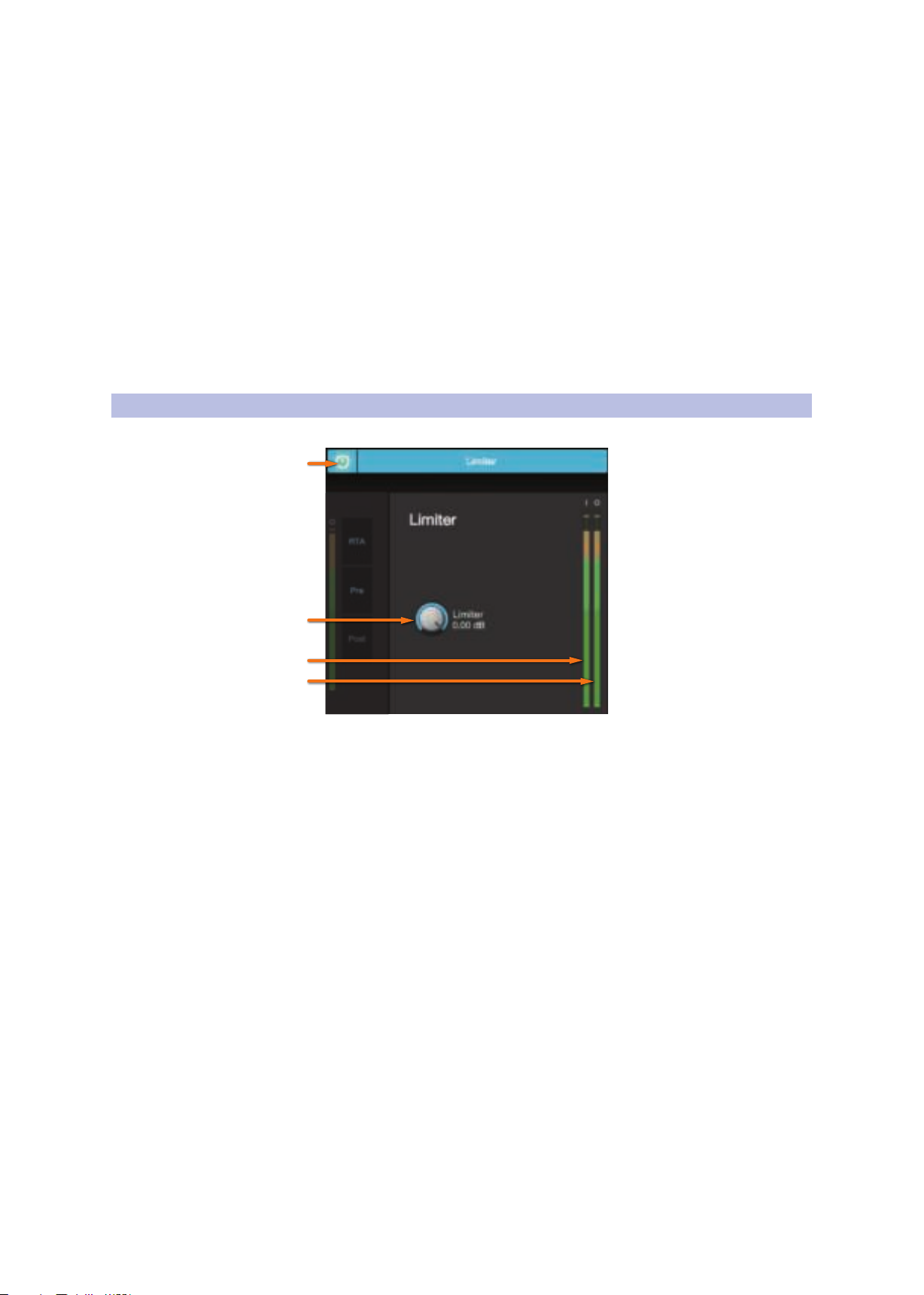
3.4 Limiter
To view the controls for the limiter, click on the Limiter tab.
1
UC Surface
Reference Manual
into a shelving EQ. A high shelving EQ is like a treble-control knob on a stereo.
In this mode, the Center Frequency control selects the shelving frequency.
Note: StudioLive AI-series mixers feature the SMAART RTA and Spectrograph tools.
Please see Section 4.1 for more information.
you to select the EQ type for the current channel.
2
3
4
1. Limiter On/Off. Turns on the limiter for the
selected input channel. The ratio is ∞:1.
2. Limiter Threshold. Sets the threshold of the limiter for the selected
channel. When the signal’s amplitude (level) exceeds the threshold setting,
the limiter is engaged. The threshold can be set from -56 to 0 dB.
3. Input Meter (Series III only). Displays the input signal to the limiter.
4. Output Meter (Series III only). Displays the outputs signal to the limiter.
17
Page 21
4 Graphic EQ
1 2 3 4 5 6 7
3.4 Limiter
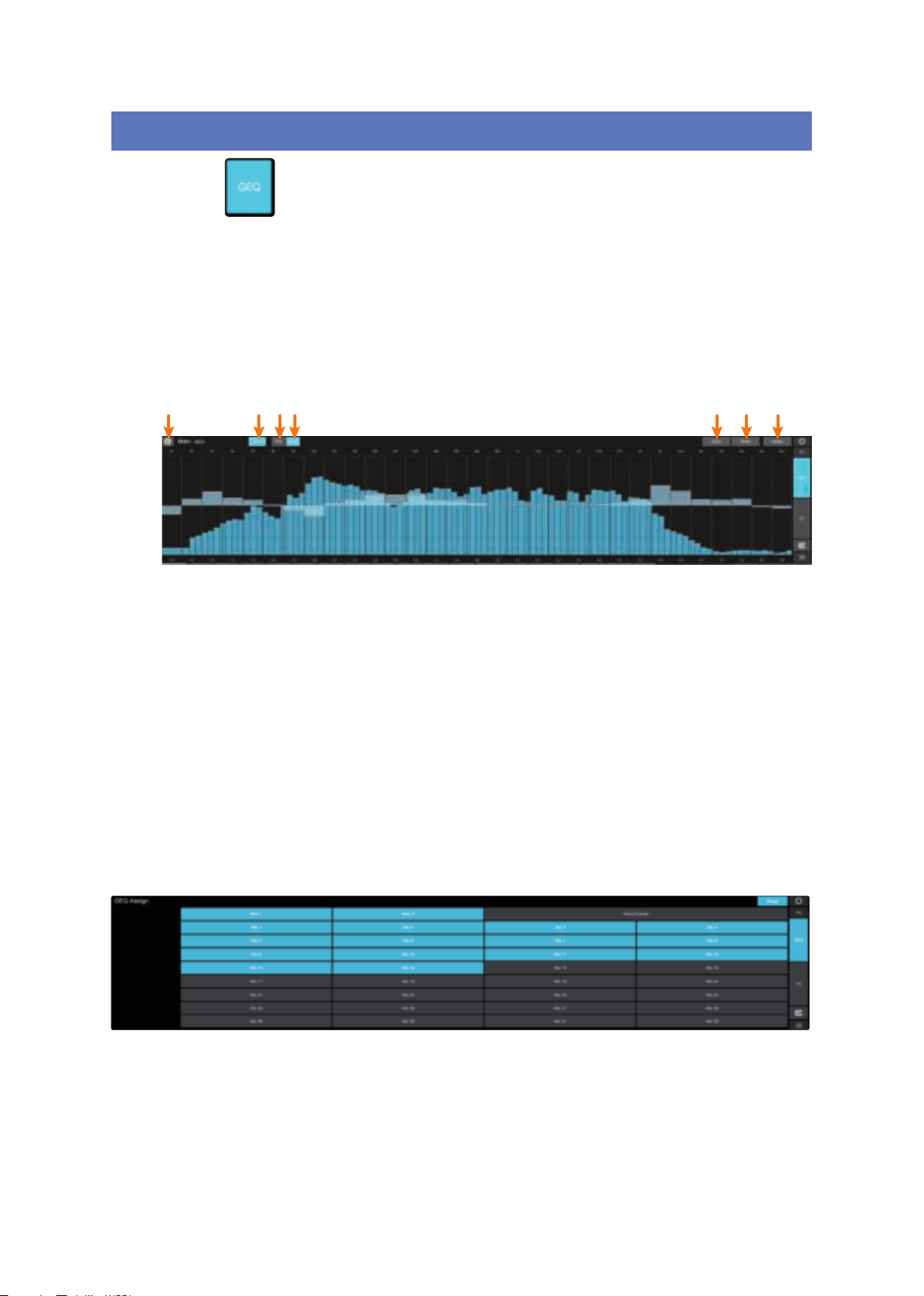
4 Graphic EQ
UC Surface
Reference Manual
To the left of the Fat Channel, you will find the GEQ button. This opens up the graphic
EQ for that bus.
• StudioLive Series III mixers provide eight graphic EQs
that can be assigned to any output bus.
• StudioLive AI-series RM/RML mixers provide a graphic
EQ for the Main bus and the first 14 aux buses.
• StudioLive AI-series console mixers provide a graphic
EQ for every aux bus plus the mains.
In general, graphic EQ settings are created prior to a live show and
are not adjusted after that. However, minor adjustments sometimes
must be made later. UC Surface makes this quick and easy.
1. GEQ On/Off. By default, all graphic EQs are disabled. To
enable any GEQ, simply click on this button.
2. RTA. Enables RTA view from within the Graphic EQ graph.
3. Pre (Series III only). Displays the Pre-GEQ signal in the RTA.
4. Post (Series III only). Displays the Post-GEQ signal in the RTA.
Note: Smaart Spectra Tools are available for StudioLive AI-series mixers from with
the Graphic EQ. See Section 4.1 for details.
5. Draw GEQ. Enabling the Draw function will allow you to draw a GEQ curve
with your finger or mouse rather than adjusting each band individually.
6. Reset GEQ. To zero out all curve settings on any graphic EQ, click on
the Reset GEQ button. This will return all band gains to 0 dB.
7. Assign (Series III only). Opens the Graphic EQ assign view:
When the Assign view is open, you can reassign Graphic
EQs to different FlexMixes and buses.
18
Page 22
4 Graphic EQ
4.1 Enabling Smaart Analysis (StudioLive AI-series only)
4.1 Enabling Smaart Analysis (StudioLive AI-series only)
Both the GEQ and Fat Channel EQ provide Smaart Spectra™ analysis
when connected to a StudioLive AI-series mixer. Smaart Spectra
was developed by Rational Acoustics to power Smaart’s Spectrum
Measurement Engines and includes an RTA and a spectrograph.
By default, Smaart® analysis is disabled. While Smaart is disabled, you have control
over which bus is routed to the second to last pair of auxiliary FireWire inputs.
Clicking on the Spectrograph or RTA buttons will start Smaart, and UC
Surface will take control over these FireWire auxiliary inputs.
For more information on the Auxiliary Inputs Router, please see Section 8.3.
Note: Smaart analysis requires use of the StudioLive AI-series’ onboard audio
interface. It is not available without a FireWire or FireWire-to-Thunderbolt
connection between your mixer and your computer. UC Surface’s integrated
Smaart modules do not support StudioLive Series III consoles.
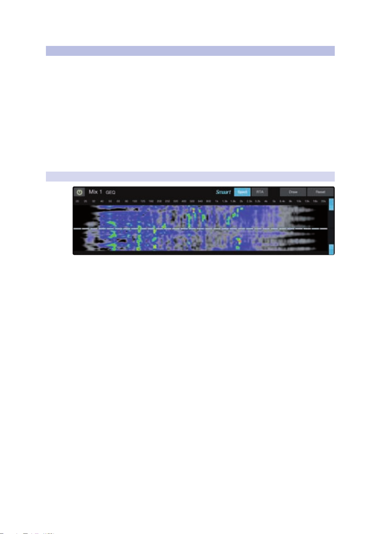
4.1.1 Time-Frequency Spectrograph
UC Surface
Reference Manual
Dynamic Range
Clicking on the Spectrograph button (from the Fat Channel EQ
or GEQ tab) will launch the Time-Frequency Spectrograph. This
spectrograph provides a three-dimensional view of your audio in
which x = frequency, y = time, and color = decibel level.
Any signal below the lower dynamic-range threshold is black. Any signal above
the top dynamic-range threshold is white. Within the dynamic range, colors go
from blue to green to red, with blue indicating the quietest and red the loudest.
Many audio signals that are encountered in the field are highly dynamic. Musical
signals, speech, and even environmental noise contain significant changes in spectral
content as a function of time. The spectrograph can be thought of as a record of
multiple RTA measurements taken over time, with color representing amplitude.
Using this function, the spectral content of the input signal is recorded as it changes
in time. This allows you to view and analyze time-varying trends in the input signal.
As a troubleshooting tool, the spectrograph is useful for finding spectral “defects”
in a system or acoustical environment. Certain audio signals or acoustical events
contain specific traits that can be easily detected due to their distinct time/
frequency signature—specifically, highly tonal sounds such as AC line noise
in an electrical signal chain or the presence of electro-acoustical feedback.
UC Surface provides dynamic-range sliders that set the maximum
and minimum volume thresholds for the spectrograph.
19
Page 23
4 Graphic EQ
4.2 Using the Smaart Spectrograph to Ring Out Monitors
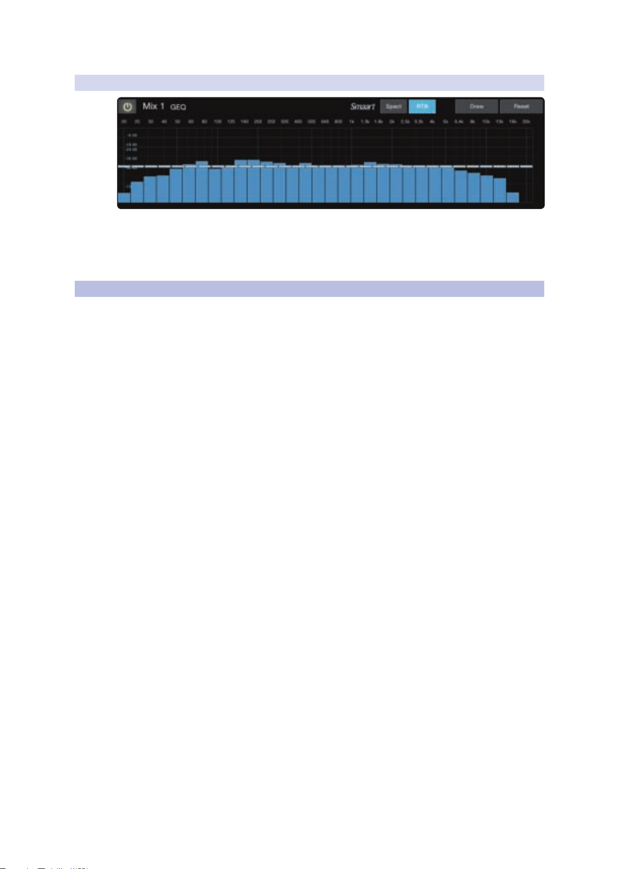
4.1.2 RTA
Clicking on the RTA button (from the Fat Channel EQ or GEQ tab) will
launch a real-time analyzer in which x = frequency and y = amplitude.
An RTA provides a close visual representation of what you are hearing. It
provides a view of the long-term spectrum of the signal, such as the onethird-octave spectrum long-term average of a musical performance.
4.2 Using the Smaart Spectrograph to Ring Out Monitors
The spectrograph shows frequency data over time, so a constant frequency,
such as feedback, results in a straight line in the spectrograph. In a feedback
loop, a portion of the signal from the speaker returns to the microphone,
resulting in a buildup of energy that creates squealing, screeching feedback.
“Ringing out” is a process of attenuating the frequencies that are feeding
back to maximize gain before feedback in your floor monitors.
UC Surface
Reference Manual
1. With the mic input gain at an appropriate level, bring the auxsend level up on the mic channel you wish to ring out.
Power User Tip: If you are using one console for stage monitors and another console
for front-of-house, set the mic input gain on the front-of-house console. Do not “gain
up” the mic signal on the monitor mixer for the sake of getting more volume out of a
stage monitor, as you can do that in other places (Mix level for individual channels,
Aux Out level for global control, etc.). Gain staging is very important in order to have
a feedback-free show.
2. Select the graphic EQ for the aux output of the stage monitor you are ringing out
3. Enable the spectrograph.
4. Slowly bring the aux output level up until you hear (and see) feedback.
Note: Ringing out stage monitors will produce feedback. If you are not careful, you
can produce a lot of feedback. Do not make sudden gain boosts; go slowly and
carefully to avoid causing any damage to speakers and ears.
5. Feedback will show up as a solid line on the spectrograph and as
a line peak on the RTA. Use the dynamic threshold to adjust how
bright, and at what input level, the frequency information plots.
6. Lower the GEQ fader for the offending frequency in 3 dB
increments to attenuate it out of your stage monitor.
Power User Tip: Bring back the level on the GEQ slider to the point just before
feedback so you don’t take out too much frequency content and sacrifice overall
timbre. Because the speaker is pointed at the mic, stage-monitor feedback typically
occurs in the higher frequencies, which also is where intelligibility comes from.
Maximizing your intelligibility and gain structure results in clearer-sounding
monitors.
20
Page 24

4 Graphic EQ
4.3 Using the RTA While Mixing
You can apply this process to the main system, as well. This is especially useful
with applications requiring lavaliere or podium mics. These types of microphones
are typically omnidirectional condensers and are very prone to feedback.
In a main system, feedback is typically in the mid to low range. The
frequencies that are regenerating and creating a feedback loop
are those frequencies that are wrapping around the main system
due to the loss of directional control of lower frequencies.
When you are ringing out a system, and more than two or three feedback
loops are happening simultaneously, you have reached the level where
stability can no longer be achieved. Try bringing down the overall output level
or find a physical solution, such as moving the speaker or microphone.
4.3 Using the RTA While Mixing
The RTA provides a view of amplitude and frequency content over a specified
plane. The ability to analyze frequency content—specifically, being able
to visualize the exact frequencies you are hearing in order to home in on
problem areas— makes it a secret weapon for many mix engineers.
Because the RTA is analyzing the channel or bus signal digitally, room and speaker
anomalies are taken out of the equation. This provides a pure measurement of
your mix, because you are measuring what is happening inside your StudioLive.
Power User Tip: The RTA can be useful in understanding what the frequency content of
an instrument when creating space for it in a mix. For example, let’s say you are mixing a
particularly edgy-sounding lead guitar that is competing with the male vocal and
distracting from the overall good tone of the instrument. By using the RTA in the Fat
Channel, you can quickly identify the offending frequency by looking for spikes in the RTA.
This saves time and frustration by taking some of the guesswork out of equalization. It
should be noted, however, that an RTA cannot be used as a substitute for careful listening.
While this tool provides a great visual analysis of your mix, critical listening must always
be your main guide.
UC Surface
Reference Manual
21
Page 25

5 Adding Effects
5.1 Editing Effects
5 Adding Effects
5.1 Editing Effects
UC Surface
Reference Manual
Your StudioLive mixer is equipped with multiple FLEX FX internal
effects processors each with a dedicated mix bus.
• StudioLive Series III 32-channel mixers have four freely assignable processors.
• StudioLive 64S mixers are equipped with eight freely assignable processors.
• StudioLive AI-series mixers have two processors dedicated for
reverb effects and two more dedicated for delay effects.
Regardless of model, the effects returns for any effect
bus can be routed to any mix bus.
Creating an effects mix is just like creating a monitor mix: Simply
click on the effects mix and select and set the level for each
channel to which you would like to apply reverb or delay.
Effects returns for each processor are available at the
end of the input channels in each mix.
To access the effects library for each processor and make adjustments to effects
parameters, click on the FX View button on the left side of the Fat Channel.
Across the top of the window, you see each of the effects buses and the current
selected effects type for each bus. To edit any effect, simply click on its bus.
This will open the effects editor. From here, you can change
the effects type, adjust parameters, and load presets.
22
Page 26

6 Presets
1
8
9
10
11
12
13
2 3 4 5 76
6.1 Fat Channel Presets
6 Presets
The presets button in UC Surface is a contextual function that follows the currently
selected mode: Fat Channel presets, GEQ presets, FX presets, or Mix Scene.
6.1 Fat Channel Presets
While the Fat Channel is active, this button launches the Fat Channel presets menu.
To close the menu and reopen the mixer view, simply click the button again.
UC Surface
Reference Manual
1. Current Channel. The Channel controls for the currently selected
channel are available at the left of the Preset Manager.
2. Previous Channel. Selects the previous channel.
3. Channel Selection. Displays the currently selected channel. The preset
manager will automatically load and store presets to and from this
channel. Click on this menu to select a new channel to manage.
4. Next Channel. Selects the next channel.
5. Copy/Paste. To copy the Fat Channel settings to another channel,
simply click on Copy, select the channel you’d like to load the
settings to from the Channel Select menu, and click Paste.
6. Preset Manager. Displays presets that are stored locally on
the device running UC Surface and presets stored locally
on the mixer. See Section 6.5 for more information.
7. Fat Channel A/B. StudioLive mixers let you create two complete Fat
Channel settings and compare the two. In this way, you can experiment
with a new sound without having to struggle to re-create your old standby,
and after several minutes of careful adjustment, you can verify that a new
Fat Channel setting is better than it was before you started tweaking.
8. Preset Category. Filters the preset list based on the selected category.
9. Load. Loads the current preset to the selected channel.
10. Save. Creates a Fat Channel preset from the currently selected channel’s settings.
11. Preset Filters. Filters a Fat Channel preset by module (Gate, Compressor/
Limiter, EQ). To load any of these preset components, just click on its button.
23
Page 27

6 Presets
1
4
5
2 3
142 3
5
6.2 GEQ Presets
6.2 GEQ Presets
UC Surface
Reference Manual
12. Audition. When the Audition button is engaged, each preset will
nondestructively load into your channel, using the currently enabled
filters. This lets you try out a preset before loading it and overwriting
the current settings. You can make changes to this preset in real time.
To load the settings you’ve auditioned, click the Load button.
13. Reset. Restores the Fat Channel to its default settings. The Preset
Load filters can be used to configure which settings will be reset.
While the GEQ View button is active, the Preset button launches the GEQ Presets
menu. To close the menu and reopen the mixer view, simply click the button again.
6.3 FX Presets
1. Recall. Loads the current preset to the selected bus.
2. Store. Creates a GEQ preset from the currently selected bus GEQ’s settings.
3. Preset Manager. Displays presets that are stored locally on
the device running UC Surface and presets stored locally
on the mixer. See Section 6.5 for more information.
4. Copy/Paste. To copy the effects settings to another bus’s GEQ,
simply click on Copy; from the GEQ Bus Select menu, select the
bus to which you’d like to load the settings; and click Paste.
5. Audition. When the Audition button is engaged, each preset
will nondestructively load into the currently selected effects bus.
This lets you try out a preset before loading it and overwriting the
current settings. You can make changes to this preset in real time.
To load the preset you’ve auditioned, click the Load button.
While the FX View button is active, the Preset button launches the FX Presets menu.
To close the menu and reopen the mixer view, simply click the button again.
24
Page 28

6 Presets
6.4 Preset Management
1. Recall. Loads the current preset to the selected channel.
2. Store. Creates an effects preset from the currently selected effects bus settings.
3. Preset Manager. Displays presets that are stored locally on
4. Copy/Paste. To copy the effects settings to another effects bus, simply
5. Audition. When the Audition button is engaged, each preset
6.4 Preset Management
Presets can be stored locally on your StudioLive mixer or locally
on your computer and copied between the two.
UC Surface
Reference Manual
the device running UC Surface and presets stored locally
on the mixer. See Section 6.5 for more information.
click on Copy; from the banner at the top of the window, select the
bus to which you’d like to load the settings; and click Paste.
will nondestructively load into the currently selected effects bus.
This lets you try out a preset before loading it and overwriting the
current settings. You can make changes to this preset in real time.
To load the settings, you’ve auditioned, click the Load button.
Syncing the Mixer Library
Presets stored in the mixer library can be copied to the device running UC
Surface either individually or you can sync the entire preset library.
To sync every preset, click or touch the Sync all button.
You can copy individual presets to and from your mixer’s
memory by simply dragging dropping them between the Mixer
and Local sections of the Library Management area.
Note: Dragging and dropping a preset allows you to overwrite currently used library slots,
so be careful where you drop it!
You can also use the Transfer buttons to transfer one preset to and from the Mixer
and Local libraries. When transferring to the Mixer library, the preset will be moved to
the first available Empty Location.
25
Page 29

7 Projects and Scenes
1
2 3 4 5 6 7 8 9 10 11 12 13 14 15
16
17
18
7.1 Project and Scene Management (StudioLive Series III)
7 Projects and Scenes
Every parameter on your StudioLive mixer can be stored and recalled later.
Global settings, like FlexMix modes, Talkback assignments, and all the routing
set in the Digital Patching menu in addition to System settings like Sample
Rate, Network Settings, and Cue Source are stored within Projects.
Because fundamental routing and bus structure is being changed
when a Project is recalled, the load time for Projects is slightly longer
than loading a Scene or Preset. It is recommended that Projects are
not loaded during a performance or other live application.
All other mixer settings like Channel Strip parameters, Fat
Channel models and settings, and Channel Identifiers like
name, color, and type are stored inside of Scenes.
Scenes that share the same Global System settings should be stored within
the same Project. Many Scenes can be stored within each Project but
scenes created in one Project cannot be recalled in any other Project.
Note: Only StudioLive Series III mixers v. 2.0 firmware and higher offer this functionality.
StudioLive AI-series mixers employ a traditional Scene. See Section 7.2 for more
information.
UC Surface
Reference Manual
7.1 Project and Scene Management (StudioLive Series III)
To access your Project and Scene Libraries, press the ‘Prj’ button.
The controls on the left side of the screen save and load Projects as well
as resets the default routing of your mixer. The controls on the right side
on the screen save and load Scenes within the current Project, as well
as resets the default state of every currently recallable parameter.
1. Project / Scene Manager Tab. Click / Tap to view, store, and
load Projects and Scenes on your mixer’s local memory.
2. Import/Export Tab. Click / Tap to transfer Project and Scenes between
you mixer memory and the device running this instance of UC Surface.
3. Currently Loaded Project. Displays the name of the Project
file that is currently loaded on your StudioLive mixer.
4. Store Project. Click / Tap to store your current global settings
as a new Project or to update an existing Project file.
5. Recall Project. Click / Tap to load the currently highlighted Project
file. Note that because Projects are altering parameters of global
functions, they take slightly longer to load. Because of this PreSonus
recommends loading Projects prior before mixing a session live.
6. Scene Safe Tab. Click / Tap to select channels that
will not be effected by a Scene recall.
7. Reset to Default. Click / Tap to reset all global parameters to their
factory default. This includes all digital patching and FlexMix modes.
26
Page 30

7 Projects and Scenes
7.1 Project and Scene Management (StudioLive Series III)
8. Lock Project. Click / Tap to lock the currently selected Project library slot.
This will prevent the file from being overwritten. When this is enabled,
no new data can be stored to this location until it is unlocked.
9. Currently Loaded Scene. Displays the name of the Scene
file that is currently loaded on your StudioLive mixer.
10. Store Scene. Click / Tap to store your currect mix settings as a new
Scene within the current Project or to update an existing Scene file.
11. Recall Scene. Click / Tap to load the currently highlighted Scene file.
12. Reset to Default. Click / Tap to reset all mix parameters to their factory default.
This will not reset Global parameters like digital patching and FlexMix modes.
13. Lock Scene. Click / Tap to lock the currently selected Scene library slot.
This will prevent the file from being overwritten. When this is enabled,
no new data can be stored to this location until it is unlocked.
14. Scene Filters. When recalling a Scene, you can choose to omit
certain sets of parameters. When a filter is blue, the parameter
set will be recalled. When grey, the parameter set will be omitted
from the recall and these settings will remain unchanged.
UC Surface
Reference Manual
7.1.1 Import /Export
15. Close Project/Scene Menu. Click / Tap to the ‘X’ to exit
and return to the mix view in UC Surface.
16. Project Filters. When recalling a Project, you can choose to omit
certain sets of parameters. When a filter is blue, the parameter
set will be recalled. When grey, the parameter set will be omitted
from the recall and these settings will remain unchanged.
17. Project Library. Every Project stored locally on your
StudioLive mixer will be displayed here.
18. Scene Library. Every Scene stored within the currently
loaded Project will be displayed here.
Projects can be stored locally on your StudioLive mixer or locally
on your computer and copied between the two.
Syncing the Mixer Library
Projects stored in the mixer library can be copied to the device running UC
Surface either individually or you can sync the entire preset library.
To sync every Project, click or touch the Sync all button.
You can copy individual Projects to and from your mixer’s
memory by simply dragging dropping them between the Mixer
and Local sections of the Library Management area.
27
Page 31

7 Projects and Scenes
7.2 Mix Scenes (StudioLive AI-series)
Note: When a Project is transferred, so are all the Scenes stored within it.
You can also use the Transfer buttons to transfer one preset to and from the Mixer
and Local libraries. When transferring to the Mixer library, the preset will be moved to
the first available Empty Location.
7.2 Mix Scenes (StudioLive AI-series)
UC Surface allows you to create and store a library of scenes. A scene is like a
snapshot of your mix: It stores each Fat Channel parameter for every analog input, as
well as each fader’s position, the aux and effects mixes, channel mutes and solos, etc.
7.2.1 Quick Scenes
The Quick Scene buttons in the Scene view allow you to create a scene without
storing it to the Scene Library, either on your mixer’s memory or in UC Surface on
your computer or mobile device and giving it a name. This is especially useful when
mixing multiple bands that you might not ever mix again. Quick Scenes are stored
in non-volatile memory and will be retained when your mixer is power cycled.
UC Surface
Reference Manual
UC Surface provide the following Quick Scene controls:
Store. To create a Quick Scene, click or tap the Store button. All
the Quick Scene buttons will flash. Click on the Quick Scene to
which you’d like to store the current mixer settings.
Quick Scenes 1-8. Loads the stored Quick Scene. This will override all the
current settings on the mixer based on the Scene filters (discussed shortly).
28
Page 32

7 Projects and Scenes
1 2 3 4
7.2 Mix Scenes (StudioLive AI-series)
7.2.2 Scenes Library
To store a scene in permanent memory, either on your mixer or locally on your
computer, press the Preset button while the Scene view is active. This will open your
Scene library. Press the button again to close it.
UC Surface
Reference Manual
1. Recall. Click on this button to load the currently selected scene.
2. Store. Click on this button to create a new scene from the current mixer settings.
3. Scene filters. UC Surface mix scenes store the settings of the entire mixer.
4. Scene Manager. Displays scenes that are stored locally on
7.2.3 Scene Safe Edit
You can choose to load the entire scene or filter various portions of it.
the device running UC Surface and scenes stored locally on
the mixer. See Section 6.5 for more information.
Engaging the Scene Safe Edit button allows you to disable
recalling any scene parameters on specified channels.
29
Page 33

7 Projects and Scenes
7.2 Mix Scenes (StudioLive AI-series)
UC Surface
Reference Manual
To enable Scene Safe mode on any channel, simply click on
it while Scene Safe Edit is engaged. Once selected, a channel
will always be omitted while recalling any mix scene.
30
Page 34

8 Quick Panel Functions
8.1 Talkback
8 Quick Panel Functions
The Quick Panel provides easy access to the following functions:
Talkback, Mute Groups, Fader Locate (StudioLive AI-series
console mixers), FX Bus mutes, and Tap Tempo.
To open or close the Quick Panel, click on the arrow in the lower right hand corner of
the screen.
8.1 Talkback
The Talkback feature lets you communicate with the performers and
audience. The talkback level is individually controllable from each mix.
You will find the level control after the input and playback channels.
Click on the Talkback button to enable the Talk function on your StudioLive mixer.
UC Surface
Reference Manual
8.1.1 Talkback Destination
To select the destination for your Talkback routing, click or tap the Talk Assign button,
then click or tap on the mix to select it. For StudioLive AI-series console mixers, the
mixes will be arranged in the same groups as the physical buttons on your mixer.
The Select buttons for the mixes to which the Talkback has been
routed will turn red to indicate that Talkback is active.
31
Page 35

8 Quick Panel Functions
8.2 Mute Groups
8.1.2 Talkback Source (StudioLive Rack Mixers)
Any channel on your StudioLive rack mixer can be designated as the talkback
source. To select a talkback source, select the talkback channel in any mix.
You will be able to select the input you’d like to use, control the preamp
level, and enable phantom power. If your mixer is connected via AVB
to a StudioLive console mixer, you can also choose the console mixer’s
dedicated talkback input by selecting “AVB” from this menu.
UC Surface
Reference Manual
8.2 Mute Groups
A mute group allows you to mute and unmute multiple channels and buses with
the press of a single button. With the eight mute groups in UC Surface, you could,
for example, assign the drum mics to Mute Group 1, the instrumentalists to Mute
Group 2, the background vocalists to Mute Group 3, all the aux buses to Mute
Group 4, all four FX buses to Mute Group 5, and every channel on the mixer to Mute
Group 6, and so on. In this way, you can quickly mute multiple channels at once.
Click on the Mute button in the Quick Panel to view the mute groups.
UC Surface provides the following mute group controls:
All On. Mutes all channels and buses. The All On Group is a preconfigured
mute group that includes every channel and bus with a Mute button.
All Off. Clears all mutes. When the All Off Button is pressed, any
channel or bus that has been muted will be unmuted.
32
Page 36

8 Quick Panel Functions
8.3 FX Mutes
Mute Group 1-8. Engages/disengages assigned mute groups.
When any of the Mute Group buttons is pressed, the assigned
group of channels or buses will be muted/unmuted.
Save. To create a mute group, click or tap the Save button. All
the Mute Group buttons will flash. Click on the mute group to
which you’d like to store the current mute settings.
Power User Tip: Both the mute groups and All On only add mutes to your mix and
remove the same mutes they added. Mute groups will not clear mutes that were active
prior to the mute group being engaged. (i.e., if a mute is engaged when its mute group or
All On are enabled, it will still be engaged when you disable the mute group or All On.)
The exception to this rule is the All Off button. This button will clear any mute that is
currently enabled and will deactivate any mute group that is active, including All On.
8.3 FX Mutes
You can mute your FX buses one of two ways: Globally or Individually. To mute every
FX bus simultaneously, click or tap on the Mute All FX button.
UC Surface
Reference Manual
To mute FX buses individually, click or tap on the FX Mutes button. This will display
individual mutes for each bus.
8.4 Fader Locate (StudioLive AI-series Console Mixers only)
StudioLive AI-series console mixers are not equipped with motorized
faders. So when you remote control your mixer from UC Surface,
the main mix you see in UC Surface and hear in your front-of-house
speakers will not match the mix you see on the physical faders.
The Fader Locate button provides a visual representation of where your physical
faders are, relative to the virtual faders in UC Surface. Moving a fader on your
StudioLive AI-series console mixer will not affect the mix until it intersects with the
current position of the virtual fader.
33
Page 37

9 The Settings Page
9.1 Device Settings
9 The Settings Page
The Settings page allows you to customize your StudioLive mixer
and UC Surface, allowing you to create a flexible mix system
for your application. From the settings page you can:
• Customize the look and feel of UC Surface
• Configure your control network settings
• Connect to EarMix 16M Personal Monitor Mixers and NSB-series Stage Boxes
• Route audio to and from the AVB Network
• Patch any input or bus to any channel or output
• Create User Profiles and customize device permissions
• Authorize additional Fat Channel plug-ins
• Back up your entire mixer
StudioLive AI-series mixers will find network customization and device permission
options as well as access to FireWire Aux Inputs routing and the Smaart Wizards.
To open the Configuration Settings page, click on the Settings button in the upper
right hand corner of UC Surface.
UC Surface
Reference Manual
9.1 Device Settings
The Device Settings tab allows you to customize your StudioLive
experience in UC Surface and manage your remote mobile devices.
9.1.1 Device Permissions
Controlling your StudioLive remotely with UC Surface or QMix-UC for
mobile devices allows you to move about the venue freely. However, it can
also put the full power of the StudioLive in multiple hands— some more
adept than others. Therefore, your StudioLive enables you to limit each
wireless device’s access to the mixer features by setting permissions.
Once a device is connected to your wireless network and has launched UC Surface
or QMix-UC, the device will be displayed in the Device Permissions list. Each device
will be listed using its device name so you can easily identify which device is which.
Once you have connected and configured a device, the same permissions
will be set for that device every time you connect it. Complete information
about QMix-UC can be found in the QMix-UC Reference Manual.
34
Page 38

9 The Settings Page
9.1 Device Settings
UC Surface Permssions
UC Surface
Reference Manual
When setting permissions for UC Surface users, you will choose between
giving full access to all mix functions or providing limited access to just
a few aux-mix functions. In most cases, one device will be configured as
front-of-house (FOH), and the others will be configured as aux mixes.
• None. The selected device will not be able to control your StudioLive mixer.
• FOH. Enables all UC Surface functions for the selected device.
• All Auxes. The selected device will only control the
channel send levels for all aux mixes.
• Aux 1... UC Surface will only control the channel
send levels for the specified aux mix.
StudioLive Series III mixers provide an added permissions layer that allows
you to make different functions available or inaccessible per device.
• Other Permissions. Use these buttons to enable access the
stated set of parameters regardless of the Mix Permission
mode you have selected for this device. This allows you further
customize the level of control you grant to each user.
Note: This features is only available on StudioLive Series III mixers.
QMix-UC Permissions
When setting permissions for QMix-UC users, you will choose between providing
full access to all aux mixes and providing access to only a single aux mix.
• None. The selected device will not be able to control your StudioLive mixer.
• All Auxes. QMix-UC will control the channel send levels for all aux mixes.
35
Page 39

9 The Settings Page
9.1 Device Settings
• Aux 1... QMix-UC will only control the channel
send levels for the specified aux mix.
When a user has access to a single aux mix, you also have the option to
limit control to the Wheel of Me only. Wheel Only disables the Aux Mix
page in QMix-UC. When this is enabled, the user will only be able to
use the Wheel of Me on the aux to which you’ve provided access.
Change Access Code
This button allows you to set a custom access code for each UC Surface device
so that once permissions have been set, they cannot be changed locally on the
device without the correct access code. By default, the access code is 12345.
9.1.1.1 Setting Permission on StudioLive AI-Series Consoles
Permissions for UC Surface can also be set from your StudioLive AI-series
console mixer. Once a tablet is connected to your wireless network and has
launched UC Surface, the device will be displayed in the Remote Devices
list on the System Menu on your StudioLive. Each device will be listed
using its device name so you can easily identify which device is which.
1. Press the System button on your StudioLive to launch the System
menu and Page down to navigate to Page 3: iOS Setup.
UC Surface
Reference Manual
2. Use the Value encoder to scroll through the list of available iOS devices.
3. When you find the device for which you’d like set permissions, use the Next
button to navigate to the first permissions field. Use the Value encoder to set the
device permission.
36
Page 40

9 The Settings Page
9.1 Device Settings
9.1.2 Configure Lockout (StudioLive AI Console Mixers)
You can lock out the functions of your StudioLive AI-series mixer
when you are away from it by creating a password.
1. To do this, you must click on the Configure Lockout button from the Settings
page.
2. Enter the 5-digit numeric passcode you would like to use.
3. To make the mixer able to be locked, enable Device is Lockable.
4. Click Set Lockout save the passcode.
Locking Your Mixer
Once the passcode has been set, you can lock or unlock your mixer any
time by navigating to Page 8 of the System menu on your mixer.
UC Surface
Reference Manual
9.1.3 Firmware
Press the Select buttons that correspond to the 5-digit code you saved. For example,
if you set the passcode as 1-2-3-4-5, you would press the Select buttons for Channels
1-5 respectively.
UC Surface allows you to view the currently installed firmware version on your
StudioLive mixer as well as the version of UC Surface you are running.
When connected both the Internet and to a StudioLive mixer, UC Surface
can check for the latest firmware version and update your mixer’s
firmware by clicking on the Check Firmware Update button.
37
Page 41

9 The Settings Page
8 9 1110 1312
9.1 Device Settings
9.1.4 System Settings
The System Settings area allows you to customize your StudioLive
mixer. The functions displayed on this page will vary depending on
what type of StudioLive mixer you have connect to UC Surface. This
section will describe the functions available for each mixer type.
9.1.4.1 StudioLive Series III Mixers
1
UC Surface
Reference Manual
2
3
4
5
6
18
17
16
15
14
7
1. Device Display Mode. Selects the viewing mode for UC Surface:
• Mixer. While in Mixer Display mode, you have access to
every function, making it great for remote mixing.
• Fat Channel. Fat Channel Display mode is designed to function
as a second screen for your mixer. In this display mode, all the Fat
Channel features for each channel will be displayed rather than every
function on the mixer. You can select a different channel to view
either from your mixer or from the meter bridge in UC Surface.
• Sends. Aux Sends mode provides two display options. While on inputs,
UC Surface will display all the bus sends for the selected channel. While on
outputs, UC Surface will display all the channels for a selected bus as well as
the bus master. Use the meter bridge to select a different channel or bus.
• Meter. Meter mode displays all the channel meters and
mutes for every input channel and output bus.
2. Sample Rate. Sets the Sample Rate for your mixer.
3. Network Clock. Sets the clocksource for networked mixers. When using two or
more mixers with stand-alone functionality on the same AVB network, only one
can be set to Internal clock. The other mixers must be set to “Network Stream.”
By default, StudioLive Series III rack mixers in Stage Box Mode default to stream.
For more information, please review the PreSonus AVB Networking Guide.
38
Page 42

9 The Settings Page
9.1 Device Settings
UC Surface
Reference Manual
4. Link Aux Mutes. Sets the operation mode for linking
mute buttons between channels and aux sends.
• Unlinked. When this mode is selected, channel mutes can be
independently controlled in each Aux Mix and the Main Mix.
• Main Mute Auxes. When this mode is selected, muting a channel
in the main mix will mute it in every aux mix. However, channels
can be muted and unmuted independently from each aux mix.
• All Aux Mute Link. When this mode is select, the channel mutes for
every aux mix are linked. In this mode, muting a channel from any
aux mix will mute it in every aux mix but not in the Main mix.
• Global Mute Link. When this mode is select, the channel mutes
for every aux mix and the Main mix are linked. In this mode,
muting a channel from any mix will mute it in every mix.
5. Peak Hold. Sets the type of metering. StudioLive mixers offer both Peak and
Peak Hold metering. To view the Peak Hold, simply enable this preference.
6. Sync Select. In situations where you are using UC Surface as a second (or third)
screen for your StudioLive mixer, you may wish to keep UC Surface and your
mixer focused on the same channel or bus. Enabling Sync Select will let you
select a channel or bus on either your mixer or on your UC Surface device.
7. Pan Mode (StudioLive 64S only). The StudioLive 64S features an
independent Mono/Center bus that can be configured either as
a mono bus or as the center channel in an LCR system. For more
information, please review the StudioLive Series III Owners Manual.
8. Phones Source. Selects the Cue Source for the headphone outputs.
9. Solo Mode (Defaults to Radio mode). These buttons let you choose
from the following behavioral modes for channel soloing:
• Latch. In this mode, you can solo multiple channels or buses at once.
• Radio. In this mode, only one channel or bus can be soloed at a
time. When this mode is chosen, the Select Follows Solo button
appears. Enabling this option causes channels and buses to
be selected for Fat Channel editing when soloed (as though
the corresponding Select button had been pressed).
• CR (Control Room). In this mode, soloed signals are sent directly
to the monitor output bus, temporarily disabling any other
signals that are routed to that output. When solo is disengaged,
any existing routings to the monitor outs are re-enabled.
10. Solo PFL On/Off. Enables Pre-Fader Listen (PFL) Soloing. The default
setting for the Solo bus is After-Fader Listen (AFL); by pressing PFL, PreFader Listening is enabled. In either mode, pressing Solo on any channel
or bus routes that channel to the Solo bus and has no effect on the main
or subgroup mixes. - PFL soloing is not available for the subgroups. - Aux
bus soloing is always PFL, regardless of whether this mode is engaged.
11. Solo Level. Controls the output level of the Solo bus.
12. Solo Selects. When Radio Solo mode is enabled, the Solo Select
option will be available. When Solo Select is active, soloing a channel
will also select it. This is available for all three solo modes.
13. Solo In Place On/Off Button. Enables Solo In Place. SIP (Solo In Place), or
“destructive soloing,” mutes every unsoloed channel on the StudioLive.
If one of the muted channels is routed to the mains or a subgroup, it
will be muted in those outputs. This also applies to soloed channels: The
output routing is still active. Note that while you can manually unmute
a channel, this mode should be used with extreme caution during a
live performance. Only the input channels can be placed in destructive
soloing. The subgroups and aux buses are omitted from SIP mode.
39
Page 43

9 The Settings Page
9.1 Device Settings
UC Surface
Reference Manual
Power User Tip: When SIP is engaged, channel mutes will only apply to the subgroup
and main bus assignments. SIP does not mute input channels in aux-bus mixes.
Because of this, you can use SIP to dial in a mix in the mains without disturbing the
musicians’ last-minute rehearsal on stage. Destructive soloing is also a great way to
tune each channel’s dynamics individually in live-mixing situations or do surgical
editing in the studio. SIP mode mutes every channel and bus that is not soloed in the
Main bus (that is, if Channel 3 is soloed, you will only hear Channel 3 in your mains).
This makes a great fine-tuning tool but it can quickly destroy a live mix. We highly
recommend that you drop out of this mode once the show has started.
14. Color Scheme. These two luminosity presets compensate
for environmental light interference.
15. Show Edit Popup. Presents a large display of parameter value for each function.
16. Colorize Channels. Custom colors shade the entire
channel strip, rather than just the channel label.
17. Channel ID. Choose between Icon only or Icon with channel number.
18. Show Filter Groups. This option allows to show or hide the filter groups
that are created automatically when channels are categorized.
9.1.4.2 StudioLive AI-series RM/RML mixers
1
2
3
4
5
6
7
8
1. Device Display Mode. Selects the viewing mode for UC Surface:
• Mixer. While in Mixer Display mode, you have access to
every function, making it great for remote mixing.
• Fat Channel. Fat Channel Display mode is designed to function
as a second screen for your mixer. In this display mode, all the Fat
Channel features for each channel will be displayed rather than every
function on the mixer. You can select a different channel to view
either from your mixer or from the meter bridge in UC Surface.
• Sends. Aux Sends mode provides two display options. While on inputs,
UC Surface will display all the bus sends for the selected channel. While on
outputs, UC Surface will display all the channels for a selected bus as well as
the bus master. Use the meter bridge to select a different channel or bus.
• Meter. Meter mode displays all the channel meters and
mutes for every input channel and output bus.
18
17
16
15
14
9
1110 12 13
40
Page 44

9 The Settings Page
9.1 Device Settings
UC Surface
Reference Manual
2. Mute All. Mutes every input and output.
3. Sync Select. Syncs channel selection between the mixer
and across all devices running UC Surface.
4. Sample Rate. Sets the sample rate for your mixer.
5. Cue Source. Sets the audio source for the cue mix.
6. Pan Mode. Sets the main bus output type as stereo
L/R or as LCR (Left-Center-Right).
7. Global Aux Mute. Controls channel mutes per mix. Setting Global Aux Mute
to “No” will allow you to mute your channels per mix on RM-series mixers.
8. Peak Hold. Sets the type of metering. StudioLive mixers offer both Peak and
Peak Hold metering. To view the Peak Hold, simply enable this preference.
9. Phones Monitor. Sets source for the headphone output.
10. Solo Mode. Sets the solo behavior:
• Latch. Multiple channels and buses can be soloed at the same time.
• Radio. Only one channel or bus can be soloed at a time.
• CR. Soloing any channel will patch the Solo bus to the Monitor bus.
11. Solo Level Control. Adjusts the overall level of the solo bus.
12. Solo PFL. Enables/disables PFL soloing.
13. Solo in Place. Enables/disables destructive solo.
14. Color Scheme. Luminosity presets to compensate
for environmental light interference.
15. Show Edit Popup. Presents a large display of parameter value for each function.
16. Colorize Channels. Custom colors shad the entire
channel, rather than just the channel label.
17. Channel ID. Choose between Icon only or Icon with channel number.
18. Show/Hide Auto Groups. Shows/hides Auto Filter DCAs. When categories
are applied, UC Surface automatically creates a Filter DCA group based on
each category. To hide these groups, simply turn off this preference.
41
Page 45

9 The Settings Page
9.1 Device Settings
9.1.4.3 StudioLive AI-Series console mixers
1
UC Surface
Reference Manual
2
3
4
5
6
8 9
7
1. Device Display Mode. Selects the viewing mode for UC Surface:
• Mixer. While in Mixer Display mode, you have access to
every function, making it great for remote mixing.
• Fat Channel. Fat Channel Display mode is designed to function
as a second screen for your mixer. In this display mode, all the Fat
Channel features for each channel will be displayed rather than every
function on the mixer. You can select a different channel to view
either from your mixer or from the meter bridge in UC Surface.
• Sends. Aux Sends mode provides two display options. While on inputs,
UC Surface will display all the bus sends for the selected channel. While on
outputs, UC Surface will display all the channels for a selected bus as well as
the bus master. Use the meter bridge to select a different channel or bus.
• Meter. Meter mode displays all the channel meters and mutes for every
input channel and output bus.
13
12
11
10
2. Sync Select. Syncs channel selection between the mixer
and across all devices running UC Surface.
3. Sample Rate. Sets the sample rate for your mixer.
4. Global Aux Mute. Controls channel mutes per mix. Setting Global
Aux Mute to “No” will allow you to mute your channels per mix.
5. Peak Hold. Sets the type of metering. StudioLive mixers offer both Peak and
Peak Hold metering. To view the Peak Hold, simply enable this preference.
6. Default Fader Locate. Enables Fader Locate mode if a fader movement is made
from UC Surface. It is highly recommended that you leave this feature enabled
if you are remotely controlling your StudioLive AI-series console mixer from a
tablet using UC Surface.
7. Phones Monitor. Sets source for the headphone and Control Room outputs.
8. Solo Mode. Sets the solo behavior:
• Latch. Multiple channels and buses can be soloed at the same time.
• Radio. Only one channel or bus can be soloed at a time.
• CR. Soloing any channel will patch the Solo bus to the Monitor bus.
42
Page 46

9 The Settings Page
9.2 Networking
9.2 Networking
9.2.1 Wired Connection
UC Surface
Reference Manual
9. Solo PFL. Turns PFL soloing on or off.
10. Color Scheme. Luminosity presets to compensate
for environmental light interference.
11. Show Edit Popup. Presents a large display of parameter value for each function
12. Colorize Channels. Allows you to add custom colors to channel strips.
13. Channel ID. Choose between Icon only or Icon with channel number.
The Network tab in UC Surface allows you to manage the network settings for you
StudioLive mixer, including managing your Wired Connection settings and
configuring stage boxes as well as other AVB peripherals.
Note: AVB Devices like NSB-series stage boxes and the EarMix 16M are not compatible
with StudioLive AI-series mixers. These products are only compatible with StudioLive
Series III mixers and other 1722.1 compliant AVB products.
When hardwired to a LAN network via Ethernet, there are three types of IP
configuration schemes available from within UC Surface. Configuring your IP address
allows you customize how your StudioLive mixer will present itself to other devices
on the network. In most cases, you will use the default Dynamic IP mode setting.
Dynamic Mode. This is the default setting for StudioLive mixers and is the most
common way you will use your mixer on a network. In Dynamic IP mode, the mixer is
assigned an IP address by a DHCP server. Because of this, Dynamic IP mode requires
that your StudioLive be connected to a network that also has a router connected.
In this mode, your mixer will request an IP address from the DHCP server when it is
powered on. The DHCP server will then answers and assign the mixer a unique IP
address. The mixer will continue to send and wait for an answer to its DHCP requests.
Static Self-Assigned Mode. When two network devices are directly
connected to each other or a switch, rather than to a network router,
they cannot have their IP addresses assigned dynamically. In this case,
the devices must be able to self-assign their own IP addresses.
The most common direct Ethernet connection scenario is while using a StudioLive
Series III console mixer connected directly to your computer to utilize DAW mode.
In this mode the mixer will automatically assign itself an IP
address in the 169.254.0.0/16 range, allowing connection
with other devices in the same IP address range.
Static Manual Mode. This mode is typically reserved for more complex networking
installations or situations that otherwise require setting static IP addresses. In
this mode, you can manually assign an IP address, subnet mask, and gateway. If
you’re not sure how to manually configure static IP address assignments, please
consult your IT administrator before attempting to configure your StudioLive
mixer in Static Manual IP Address mode. Unless you have a specific need for static
43
Page 47

9 The Settings Page
9.2 Networking
IP address assignment, most users would be advised to use Dynamic mode and
let IP addressing be handled automatically by your router/network DHCP server.
Power User Tip: Network modes are not intended to be changed on the fly. To ensure
proper network configuration and connection, always power cycle your StudioLive mixer
after changing its IP assignment mode.
9.2.2 Stagebox Setup (StudioLive Series III only)
UC Surface
Reference Manual
StudioLive Series III rack mixers can be configured as stage boxes for StudioLive
Series III console mixers using the touchscreen on your console mixer or from
UC Surface. The Stagebox Setup area on the Networking tab mirrors the same
functions that are available from the touchscreen on your console mixer.
To configure you rack mixer, select it from list at the left.
If you have more than one rack mixer connected to the network and are unsure
which mixer is which, you can press the Identify button. This will flash the front panel
LEDs on whichever mixer is currently selected.
Select the Stagebox Mode you would like to use and click or tap the Apply button.
Power User Tip: Connecting to your mixer and selecting the mode can be one or two
steps. When Apply is pressed, both the selected mixer and the selected Stagebox Mode are
saved simultaneously.
To route your streams, use the AVB Inputs tab.
For complete information on Stagebox Modes and AVB Inputs routing,
please review the StudioLive Series III Stagebox Mode addendum.
44
Page 48

9 The Settings Page
9.2 Networking
9.2.3 EarMix Setup (StudioLive Series III only)
EarMix 16M Personal Monitor Mixers can be connected and configured
from the EarMix Setup area on the Network tab. For complete
instructions, please review your EarMix 16M User Manual.
9.2.4 Wireless Connection (StudioLive AI-series only)
UC Surface
Reference Manual
When using the wireless LAN adapter with your StudioLive AI-series
mixer, this section will display both your mixer’s current IP address and
the wireless network to which your mixer is currently connected.
By default, your StudioLive AI-series mixer is set to connect to a wireless network
named “studiolive” with a password of “studiolive.” To change the wireless network to
which your StudioLive AI-series mixer, click on the Wireless Settings button.
9.2.5 Cascading Mixers (StudioLive RM/RML mixers)
There are a few different ways to use cascaded RML-series mixers.
For all configurations, you’ll need to connect the mixers via Ethernet
using a compatible AVB switch like the PreSonus SW5E.
In the Cascading Mixer Setup section of the Network tab, select the
mixer you’d like to be Channels 33-64 from the drop-down list.
Note: Establishing the cascaded connection may take several seconds. When
complete, you’ll see each mixer displayed in the Master and Slave unit spaces.
45
Page 49

9 The Settings Page
9.3 Backup
9.3 Backup
UC Surface
Reference Manual
Once your mixers are cascaded, they will function as a single 64-channel mixer.
The tab at the top of the screen for the slave mixer will go away and when
looking at the mixer view in UC Surface, you will see 64-channels. Channels 1-32
will reside on the master mixer, and Channels 33-64 will reside on the slave.
To remove the cascade, select None from the “Cascade with mixer” drop-down list.
If you’re using a StudioLive CS18AI, select either mixer from the drop-down list in the
UCNET screen, and you’ll have control of both mixers as a single 64-channel system.
The Backup tab displays any backup logs that have been created in UC
Surface. The Backup tab allows you to create complete, time-stamped
snapshots of your StudioLive. This can be especially useful when
completing a project that may need to be revisited in the future.
To create a backup, simply click on the Backup button.
To restore any backup file, select it and click the Restore button.
9.4 Plug-ins (StudioLive Series III Mixers)
StudioLive Series III Fat Channel Plug-ins allow you to enhance your StudioLive®
Series III mixer and Studio One® Fat Channel with additional processor models.
These plug-ins are virtual signal processors that load in your StudioLive Series III
console or rack mixer’s Fat Channel, expanding your compressor and EQ processor
libraries. Each plug-in comes in both StudioLive Series III format and Studio One
format so you can use your new processor on your computer and in your mixer.
The Classic Studio, Modern Classics, and Vintage Channel Strips bundles are available
individually from your authorized PreSonus dealer or from shop.presonus.com.
Or buy all three bundles—12 processors in all—in the Fat Channel Collection,
Volume 1, to supercharge your StudioLive Series III mixer and Studio One®.
46
Page 50

9 The Settings Page
9.5 User Profiles (StudioLive Series III Mixers)
9.5 User Profiles (StudioLive Series III Mixers)
User Profiles allow you to create custom settings limiting access to
certain functions. A specific project and scene can also be assigned
to each Profile so that when the user logs into the mixer, they will
have the option to load their preferred configuration.
UC Surface
Reference Manual
9.5.1 Default Administrator
User Profiles must be activated on your mixer. By default, your
mixer is logged into the Default Adminitrator profile. This profile
has access to every setting and parameter on your mixer.
A default Project and Scene can be added to the Admin profile, click or tap to edit.
Several customized settings can be added to the Default Administrator profile.
Once a project is selected, you can select a default Scene from within it.
Power User Tip: You can set the Default Project and Scene simultaneously, by selecting
either option. While any Project can be set as the default, only Scenes within the Default
Project can be chosen as the default.
47
Page 51

9 The Settings Page
9.5 User Profiles (StudioLive Series III Mixers)
Add a password
Click or Tap on the Change Password button to password protect
the Default Administrator profile. If you log out of this profile, you
will be prompted to enter the password to log back in.
Reset Profile
To reset the profile to default state, press the Reset Profile button.
9.5.2 Creating a New Profile
UC Surface
Reference Manual
Select a Name
Select an Avatar
You can create up to 10 User Profiles in addition to the Default Administrator profile.
To customize any profile, simply select it from the list.
Power User Tip: You must be logged into an administrator (default or custom) to create a
new User Profile.
Tap on the default name field to enter a custom profile name. The only
name that cannot be changed is the Default Administrator.
By default, the PreSonus logo is the avatar for every user. This can be changed by
tapping the default avatar on the profile settings page.
Profile Type
You can create two different Profile Types: Admin and User. Admin profiles are given
access to every function and parameter. User profiles can have their permissions
limited. For more information on setting User Permissions, see Section 12.2.3.
48
Page 52

9 The Settings Page
9.5 User Profiles (StudioLive Series III Mixers)
Default Project and Scene
Just like for the Default Administrator profile, you can select a
Project to be loaded when someone logs into their User Profile.
This is especially useful for less experienced users.
Tapping on either the Default Project and Scene field will open the User Profile
Default Project/Scene list. From here you can select the Default Project and Scene.
Note: While any Project can be selected as default, only a Scene that is stored within the
designated Default Project can be selected.
UC Surface
Reference Manual
Change Password (Optional)
Click or Tap on the Change Password button to password protect the profile. If you
log out of this profile, you will be prompted to enter the password to log back in.
Reset Profile.
To reset the profile to default state, press the Reset Profile button.
9.5.3 Edit User Permissions
When a User Profile is set to “User,” permissions can be
granted for certain functions and denied for others.
The following features are only accessible from Administrator
Profiles and always locked out in every User Profile:
• System Settings
• Audio Routing Options
• Input Source Patching
• UCNET Options
• Scene Lock / Unlock
49
Page 53

9 The Settings Page
9.6 Digital Patching (StudioLive Series III only)
From the Edit Permissions screen, you can limit access to
the following functions on a per User basis:
• Channel / Bus Names. This locks the ability to rename any Channel or Bus.
• Channel Types. This locks the ability to change the Channel Type.
• Input EQ/Dynamics. This locks the ability to control Gate,
Compressor, EQ, and Limiter parameters for every input channel.
• Output EQ/Dynamics. This locks the ability to control Compressor, EQ,
and Limiter parameters for every output bus as well as Output Delay.
• Preamps. This locks the ability to adjust the Input trim, Digital Gain,
Phantom Power, Polarity, High Pass Filter, and Input Delay.
• GEQ. This locks the User out of the GEQ menu completely.
• Assigns. This locks the ability to make any channel
assigments to the Main bus or Subgroups.
• Changing FX Types. This locks the ability to change the effects
types loaded into the StudioLive Series III Effects Rack.
• Save Scenes. This locks the ability to save or create new scenes.
• Changing / Adding DCA Filter Groups. This locks the ability to create or alter
DCA Filter Groups.
UC Surface
Reference Manual
9.6 Digital Patching (StudioLive Series III only)
Digital patching allows you to route any analog or digital input to any
channel and any mix to any output. This can save you hours of frustration
having to rewire and repatch your physical inputs and outputs, especially
in a fixed installation. Digital patching also allows you freely route audio
to your AVB network and record anything you’d like via USB.
Press the Master Reset to reset all routings to their default state.
9.6.1 Input Source
Selecting the Input Source tab will allow you to patch any source type to any
channel. This also provides you with a global view of what type of source is
routed to each channel, as well as allows you globally configure all of your
source routings for each type. For example, while the USB tab is active, you
can patch every desired USB return to every channel on your mixer.
50
Page 54

9 The Settings Page
9.6 Digital Patching (StudioLive Series III only)
9.6.2 Input Patch
From the Input Patch tab, you can route any input to any channel. This
allows you to select the sources for all input types (Analog, AVB, USB, and
SD). From this menu, you can, for example, route Analog Input 10 and USB
Return 17 to Channel 1 on your mixer. You can then toggle between the
two sources using the USB and Analog source controls for your mixer.
Pressing the Reset Sends button will reset the default routing.
Power User Tip: The routing you select for each source type is saved. In this way, you can
switch between custom Analog, Network, and USB routings just as you can with the
default routings.
UC Surface
Reference Manual
9.6.3 Analog Sends
Selecting the Analog Sends tab will allow you to patch any mix (FlexMix, Subgroup,
FX Mix, Main Left, Main Right, Solo Left, or Solo Right) to any FlexMix output.
Pressing the reset button will reset the default routing for the currently selected
input type.
51
Page 55

9 The Settings Page
9.6 Digital Patching (StudioLive Series III only)
9.6.4 AVB Sends
Selecting the AVB Sends menu will allow you to patch
any channel send or mix to any AVB output.
Pressing the Reset Sends button will reset the default routing.
The following local StudioLive sources can be sent out to the AVB Network:
• Every Input Channel
• Aux In A L and R
• Aux In B L and R
• Tape In L and R
• Talkback
• Every FlexMix
• FX Send Mix A-D (pre-effects processor)
• Subgroup A-D (32-channel models only)
• Main Mix L and R
• Main Mono/Center (StudioLive 64S)
• Solo L and R
UC Surface
Reference Manual
52
Page 56

9 The Settings Page
9.6 Digital Patching (StudioLive Series III only)
9.6.5 USB Sends
Selecting the USB Sends tab will allow you to patch any
channel send or mix to any USB driver send.
Pressing the Reset Sends button will reset the default routing.
UC Surface
Reference Manual
9.6.6 SD Sends
The following local StudioLive sources can be sent to the USB
bus to be recorded in your favorite DAW application:
• Every Input Channel
• Aux In A L and R
• Aux In B L and R
• Tape In L and R
• Talkback
• Every FlexMix
• FX Send Mix A-D (pre-effects processor)
• Subgroup A-D (32-channel models)
• Main Mix L and R
• Main Mono/Center (StudioLive 64S)
• Solo L and R
Selecting the SD Sends tab menu provides routing
the onboard SD recorder as follows:
• StudioLive Series III 32-channel models. This router allows you
to patch any mix to the last stereo pair of SD Card recording inputs
(33-34). The Main Mix, any FlexMix pair, or any fixed Subgroup
pair can be routed to these tracks on your SD Recorder.
53
Page 57

9 The Settings Page
9.7 Aux Routing (StudioLive AI-Series Mixers)
• StudioLive 64S. Because the StudioLive 64S is equipped with more
channels than the onboard SD Recorder can record, the SD Sends router
allows you to route any channel or bus to any of the 34 available tracks.
Pressing the Reset Sends button will reset the default routing.
9.6.7 AES
Selecting the AES tab allows you to route any mix pair
to the AES output on your StudioLive mixer.
9.7 Aux Routing (StudioLive AI-Series Mixers)
UC Surface
Reference Manual
In addition to the 32/24/16 input channels, the StudioLive AI-series mixers allow
you to route a number of other buses and other inputs. This is done via the Aux
Router tab. To route these additional digital sends, simply patch them to a stereo
pair of auxiliary inputs of your choice. Remember, all of these buses and inputs are
automatically set to send their signals post-Fat Channel dynamics and post-EQ
(where applicable). The inputs and buses selected in the Auxiliary Input Router will
be displayed in your recording application, along with the name of their routing.
The Aux Router also allows you to designate a specific bus to
the S/PDIF output and enables you to select which stereo pair
will be recorded on the auxiliary stereo track in Capture.
As previously mentioned, if Smaart Spectra tools are engaged, UC
Surface will take control of the second-to-last pair of auxiliary inputs.
When Smaart has control, these inputs will be grayed out.
54
Page 58

9 The Settings Page
9.8 Smaart System Check Wizards (StudioLive AI-series only)
9.8 Smaart System Check Wizards (StudioLive AI-series only)
When connected to a StudioLive AI-series mixer, UC Surface includes three System
Check Wizards to provide you with the ability to view the frequency response of the
venue; quickly calculate and set delay system timing; and verify output connectivity.
Note: Smaart System Check Wizards are not available with StudioLive Series III consoles.
Traditionally, in professional sound reinforcement, the mixing console is there to
mix, and the system processor is there to align and tune the speaker system. When
functioning and set correctly, the system processor is invisible to everyone but
the System Engineer. For the first time, the tools used to tune and align speaker
systems are built into the mixing console itself and accessible to any engineer
who wants to improve their PA’s sound and get the most out of their PA system.
For all but the most seasoned professional sound technician, this is a new extra
step in the process of setting up for a show. For most FOH engineers, getting a
good mix is a big victory. But imagine being able to recreate that same killer mix
night after night, show after show. Once the system has also been optimized
for the environment it is in, any FOH engineer working on it will achieve that
big victory without so much work. This is why system alignment is a standard
procedure in professional level sound reinforcement. Again, this solution is not
typically achieved from the mixing console, but built into the system design itself.
The Smaart System Check Wizards in UC Surface merge these two worlds.
Clicking on the Smaart Wizards tab in the Settings page will launch Smaart System
Check mode. While in this mode you can launch any of the following wizards:
• SRA: Smaart Room Analysis generates a frequency-response trace
and overlays it on the parametric EQ in UC Surface so you can adjust
your system to get rid of unwanted anomalies in the room.
• SSD: Smaart System Delay calculates and sets the correct
amount of delay time between two full-range systems.
• SOC: Smaart Output Check verifies that your system outputs
are routed correctly and are passing signal.
To run any of the Smaart System Check Wizards, UC Surface
will need to take over your mixer. When you first click on the
Smaart Wizards, you will see a warning to this effect.
UC Surface
Reference Manual
Clicking on the “Proceed” button will launch the Wizard select window and you will
no longer have control over your mixer. You can exit the Wizards and regain control
at any point simply by clicking on one of the other tabs or closing the Settings Page.
Note: To run the SRA and SSD wizards, you will need to connect a measurement
microphone to your StudioLive’s Talkback input. You’ll also need a mic stand and a long
enough cable to place the mic in front of your speakers.
A measurement microphone is special type of condenser microphone
that is designed to provide an accurate reproduction of a room’s sound
characteristics for use with audio-analysis tools, such as RTAs and spectrographs.
55
Page 59

9 The Settings Page
Sound System
Reference Signal
(Input Signal)
Measurement Signal
(Output Signal)
Reference Channel RTA
(Pink Noise)
=
Measurement Channel RTA
Frequency Response Trace
9.8 Smaart System Check Wizards (StudioLive AI-series only)
Measurement microphones typically have an omnidirectional polar pattern
and deliver a very flat frequency response between a low end of 5 Hz to 30
Hz and a high end of 15 to 30 kHz. While measurement microphones can
be quite expensive, most affordable models will do the job nicely when
paired with the Smaart System Check Wizards. PreSonus offers the budgetpriced PRM1 Precision Measurement Microphone for this purpose.
9.8.1 Smaart Room Analysis Wizard
The SRA Wizard is an automated process that will guide you through the steps
of acquiring a frequency-response trace for your audio system. A frequencyresponse trace is the plotted result (frequency and amplitude) of the system
measurement. This measurement is calculated using Rational Acoustics’
transfer function, which is a set of proprietary algorithms that compare the
signal from a measurement mic to computer-generated pink noise.
UC Surface
Reference Manual
To launch the Room Analysis wizard, click on the Room Analysis tab
and follow the onscreen instructions. Click OK to start the wizard.
Next you will be asked to pick the type of analysis you would like to do. Basic
Analysis requires you to take a single measurement of your system. When analysis
is complete, the wizard will continue to output pink noise through your system
while you EQ, allowing you to view the effects of your filters in real-time.
Advanced Analysis requires you to take three separate measurements
and will generate a more accurate frequency-response trace of your
system by averaging the measurements together. Once the trace has
been generated, this wizard will not continue to analyze your system. To
view the effects of your filters, you must run the wizard again. Skip to the
next part of this section for more information on Advanced Analysis.
56
Page 60

9 The Settings Page
1
9.8 Smaart System Check Wizards (StudioLive AI-series only)
Note: StudioLive RM/RML users must first select a talkback input from the talkback
channel. Once selected, this will be the input source targeted by the Smaart Room
Analysis Wizard.
Basic Analysis Mic Placement
Place your microphone on-axis in front of the speaker you want to analyze. If you
are analyzing a stereo bus, place your microphone on-axis in front of the Left
speaker. See Section 9.8.4 for tips in choosing the best primary mic position.
Advanced Analysis Mic Placement
As previously mentions, you will analyze your speaker from three different positions.
For the first analysis, place your microphone on-axis in front of the speaker you want
to analyze. If you are analyzing a stereo bus, place your microphone on-axis in front of
the Left speaker. See Section 9.8.4 for tips in choosing the best primary mic position.
On-Axis
UC Surface
Reference Manual
Off-Axis A
The next two measurements will be taken off-axis. Place your
microphone off-axis in front of the same speaker. See Section 9.8.4 for
tips in choosing the best secondary and tertiary mic positions:
2
57
Page 61

9 The Settings Page
9.8 Smaart System Check Wizards (StudioLive AI-series only)
Off-Axis B
3
Power User Tip: In most cases, you will want to EQ the left and right side of a stereo
system the same. This is why the SRA wizard asks you to measure the left side of your
system only and linked buses are displayed as such. If you are in an unusual situation
where you need to separately EQ each side (say, you are using a different model 15-inch
speaker on the left side than you are on the right side), connect your system to a pair of
subgroup outputs and do not link them.
UC Surface
Reference Manual
9.8.2 Smaart System Delay Wizard
Using multiple sets of speakers in a live performance can make a huge difference
in the quality of the sound. Rather than relying on a pair of front-of-house speakers
to fill the entire room, you can create listening zones throughout the room so
that your front-of-house system only needs to be loud enough to cover the
front of the room. This allows you to lower the level, give the front row listeners’
ears a break, and get better fidelity from your speakers. Sounds great, right?
However, it’s not as easy as just bringing an extra pair of speakers. Any additional
sets of speakers will need to be delayed; otherwise the audience will perceive
that the sound is coming from the walls, rather than from the stage. Even
worse, since electricity travels much faster than sound, listeners in the rear of
the room are likely to hear the sound coming from the nearest set of speakers
before they hear the sound from stage, which can dampen the attack and
intelligibility of the sound and create an unpleasant phasing effect. To compensate,
you need to delay the signal going to the additional sets of speakers.
Sound travels at a rate of 1,130 feet per second, providing that the temperature,
humidity, and air pressure are all “normal.” Therefore, it takes 1 ms for sound to travel
1.1 feet. But what if you’re setting up for an outdoor show in, say, Baton Rouge,
Louisiana, in August, when the temperature and humidity are unpleasantly far above
“normal”? Your calculations might be a little off, unless you happen to be a whiz at
calculating the effect of barometric and atmospheric pressure on sound waves.
The SSD wizard is an automated process that calculates and sets the correct
delay time between two full-range systems. The purpose of this wizard is to
set the delay time for a secondary system that is being fed from one or more
subgroups. No calculators, slide rules, or finger-counting are necessary!
58
Page 62

9 The Settings Page
9.8 Smaart System Check Wizards (StudioLive AI-series only)
STAGE
FOH L FOH R
UC Surface
Reference Manual
30 Feet
Side Fill
(left)
40 Feet
Rear Fill
(left)
inconveniently positioned column
In the example, you see three sets of speakers: main front-of-house, sidefills
for the middle of the room, and rear fills for the back. As a general rule, you
should set the delay on a satellite system based on its distance from the
next closest system to the mains. In this case, you’ll set the delay on the
sidefills based on their distance from the main front-of-house system and
the delay for the rear fills based on their distance from the sidefills.
When using the SSD wizard for the above system, you would run the
wizard four times. The first time, you’d use the main front-of-house left
for the main system and the left sidefill for the delay system. The second
time, you will use the left sidefill as the main system and the left rear-fill
for the delay system. Then repeat the procedure for the right side.
Note: it is important that you set the delay on the first satellite pair before you set the
delay on the subsequent satellite pair.
Power User Tip: Because rooms often have inconveniently placed architectural features—
fire exits, tables, and so on—the left and right side of a system with satellites will rarely be
equidistant on both sides of the system. Because of this, you need to run the wizard for
each side of a stereo system, starting at the front and working your way to the back.
Please note: the SSD wizard is not designed to analyze systems that include a subwoofer.
Temporarily disconnect or disable your subwoofer before beginning analysis.
30 Feet
Side Fill
(right)
37 Feet
Rear Fill
(right)
59
Page 63

9 The Settings Page
9.8 Smaart System Check Wizards (StudioLive AI-series only)
System Delay Wizard
To launch the System Delay Wizard, click on the System Delay tab and select the
speaker output you want to delay. From the bottom pull-down menu, select
the speaker output to which you’d like to align. This can be your main outputs
or any of the subgroup outputs, even if the subgroup outputs have been
delayed. Click OK to start the wizard and follow the onscreen instructions.
Note: StudioLive RM/RML users must first select a talkback input from the talkback
channel. Once selected, this will be the input source targeted by the Smaart System
Delay Wizard.
Once you have positioned and delayed your satellite system, you will want to
match the output levels of the main and delay systems. To do this, use an SPL
meter to match the output of the main and delay systems at the delay-system
measurement position. This means that if you are standing 20 ft from the left side
of the main system and 30 ft from the left side of the delay system, and the output
of the main system is 85 dB, the output of the delay system should also be 85 dB.
Note: For delay times between 0 and 50 ms, the delay will be set to the nearest 0.5 ms;
between 51 and 100 ms, the delay will be set to the nearest 1 ms; and between 102 and
300 ms, the delay time will be set to the nearest 2 ms.
UC Surface
Reference Manual
Delay System
Measurement Position:
1) Frequency Response
M
AIN
DELA
Y
FOH Mix Position
(SRA Wizard)
2) Delay Time
(SSD Wizard)
3) SPL Reference Point
Page 64

9 The Settings Page
9.8 Smaart System Check Wizards (StudioLive AI-series only)
9.8.3 Smaart Output Check Wizard
It’s five minutes before a show, and suddenly the drummer says there’s nothing
coming out of his monitor. Or you do a friend a favor and run sound at her club
because she has the flu, and you show up not knowing which aux is connected
to what monitor or which sub is controlling what sidefill. The Smaart Output
Check wizard was designed to make these problems disappear like magic!
By momentarily taking over the routing and volume control of an output and
patching pink noise to it, the Smaart Output Check wizard lets you quickly
discover which speaker is connected where and helps you quickly get to the
root of a routing problem. In the case of the drummer with silent monitor, if he
hears pink noise, you can save yourself ten minutes of frantic cable tracing only
to discover the output level was inadvertently turned down on his aux mix.
UC Surface
Reference Manual
9.8.4 Mic Position
Primary Mic Position
Click on the Output Check tab to use the Smaart Output Check wizard. You will
be shown buttons for all outputs on your StudioLive. Click on an output’s button,
and pink noise will fade in for three seconds. You can click on the button again
to stop it. To adjust the pink noise, use the fader on the right side of the page.
The SRA and SSD wizards do all of the calculations and complex routing through the
StudioLive for you. Two very important decisions are up to you: Where to place the
mic and, in the case of the SRA wizard, what to do with the frequency-response trace.
Improper mic placement can create “problems” in your trace
that actually don’t exist in your sound system.
This is the main reference point for a speaker and can be used
as a single, “representative” position if you’re short on time or
patience and just want to get a “gut check” of your system.
Your goal in setting the primary mic position is to find a point that puts
the microphone in the center (on axis) of a speaker’s throw, within
the listening area. In other words, you want to put the microphone
smack dab in the middle of where your speaker sounds its best.
1
61
Page 65

9 The Settings Page
Reflection arrives ~4ms late...
9.8 Smaart System Check Wizards (StudioLive AI-series only)
Secondary Mic Position
You will use two different secondary positions in a multi-point measurement. These
can be on- or off-axis measurements of a speaker within the listening area. This will
allow the SRA wizard to create an average frequency response of your sound system.
Avoid using locations outside the core coverage area of your system or on the edges.
The graphic below displays some good secondary measurement positions relative
to the primary position, as well as some positions that would be more problematic
than useful. With any mic position, avoid creating position-related anomalies.
X
2
2
2
1
2
2
2
2
2
2
2
UC Surface
Reference Manual
A word of caution about ground bounce: Ground reflections become an
issue when a speaker is flown and angled down. The proper mic position,
in this case, will also catch the reflection of the signal off the floor.
62
Page 66

9 The Settings Page
9.8 Smaart System Check Wizards (StudioLive AI-series only)
In this case, you can choose from three options:
• Block the reflection with a baffle that is large enough to
be effective above 100 Hz (so at least 5’ by 5’).
• Do a ground-plane measurement.
UC Surface
Reference Manual
• Do a multi-point measurement. Enough measurement
positions will randomize the effect of the floor bounce.
63
Page 67

9 The Settings Page
9.8 Smaart System Check Wizards (StudioLive AI-series only)
9.8.5 System Alignment Rules
The visual result of a sound-system test can be a powerful tool;
however, like any powerful tool, you must be responsible about
how you wield it. Here are few basic principles to follow:
Solve the problem at its source. The closer to the source, the more effective
the solution will be. If your kick drum lacks punch in the mix, take a look
at the kick-drum channel’s EQ and dynamics processing. Is the kick drum
properly tuned? Are you boosting the attack of the kick beater enough
and at the right frequency? Is your compressor’s attack too long?
Use the right tool. The system EQ is the last in a long line of possible solutions
to frequency problems. Once you have fully assessed the problem, you
can choose the right tool. Check the acoustic space, choice of equipment,
and system design first. Obviously, you don’t always have control over the
acoustic design or treatment (or lack thereof) of a room, and your wallet
might determine your choice of speakers more than your needs do, but
usually you have some control over your sound system’s design.
Can you raise the speakers to mitigate some of the harsher
reflections? What about widening the stereo field?
After you’ve ruled out physical solutions to a sound problem, move on to level and
delay. Can you simply lower the level of your subwoofer to kill some of the boom
in the room? Can you delay your front-of-house speakers by a few milliseconds
so that they’re in alignment with the guitar cabinets blaring from stage?
If you can’t find a physical solution and can’t mitigate the issue with
level and delay control, it’s time to employ the system EQ.
A frequency-response trace is not a video game. Your goal is to fix your
system and make it sound the best it can, not create an EQ curve that is an exact
inversion of the frequency-response trace. Mix with your ears, not your eyes.
An analyzer is a tool; you are the carpenter. You decide where
to measure your speakers. You decide what the resulting data
means. You decide what (if anything) to do about it.
UC Surface
Reference Manual
9.8.6 Using the Trace: Spotting the Trend
As discussed in the previous section, many factors can affect the response
of a sound system: the room, system configuration, electronics, wiring, and
more. Part of understanding what you see is knowing what you should
not be seeing—or at least having a basic idea of what to expect. After
all, you are trying to sculpt the EQ curve of the system into something
that compliments that sound system’s frequency response.
For example, a small system without a subwoofer can’t reproduce much energy
below 50 Hz. In fact, this frequency cutoff could be even higher, depending
on the size of the speaker, its factory tuning, porting, etc. This means that
if you are analyzing a system that is comprised of two 2-way, 12” powered
speakers, you should expect your frequency-response trace to drop off
around 50 Hz or so (depending on the frequency response of your speakers).
Because of this, boosting low frequencies in this type of system wouldn’t
achieve much and may introduce more problems than it would solve.
64
Page 68

9 The Settings Page
Subs
2 to 4 kHz
Subs
Extended LF
2 to 4 kHz
Subs
9.8 Smaart System Check Wizards (StudioLive AI-series only)
Power User Tip: A subwoofer can significantly change the frequency response of a
full-range system. A 3-way system with a subwoofer will be 6 to 18 dB hotter below
80 to 100 Hz than a 3-way system without a subwoofer.
Keep this in mind when viewing your trace.
Different types of live performances make different demands of a PA system.
A classical concert has very different needs from a rock concert. Just as you
wouldn’t mix an evening of Bach quartets the same as an evening of thrash metal,
you don’t want to tune your PA system the same for both types of events.
A classical concert doesn’t need an exaggerate subwoofer output. The audience
and performer expect and want a natural reproduction of the music. In contrast,
systems that are tuned for a rock show will use subwoofers essentially as an
effect. This is how they achieve those pummeling kick and toms and huge
bass guitar sound: the system is pre-tuned with more bass response.
In other words, you can stack the deck to be assured of a big FOH mix win. In system
alignment, this deck stacking is called “trends.” Every genre and performance type
requires a different type of trend. The sole objective of a system EQ is to smooth
out the sound system by creating a uniform slope that the system follows. This
will give your system a more uniform sound and performance, as well as better
clarity, because your system has been pre-EQ’d to meet the needs of the concert.
Below are some examples of trends for various applications:
UC Surface
Reference Manual
Music Concert
Rock Concert
Music Playback/Reproduction
65
Page 69

9 The Settings Page
2 to 4 kHz100 Hz
Subs
2 to 4 kHz
9.8 Smaart System Check Wizards (StudioLive AI-series only)
Speech Intelligibility
Power User Tip: The amplitudes depicted in the trend examples shown here are
guidelines: examples of very general slopes required for different applications. The
desired value will be different for every gig, and it is ultimately up to you to decide what is
required for your show, based on what type of artist is performing and what kind of
sound system you are using. While making a trace follow these trends is recommended,
in real-world applications, this might not always be possible. Being able to compromise
and work with what you have, often requires a certain amount of creativity and artistry
on the part of the system engineer.
9.8.6.1 Spotting the Trend: Real World Example
UC Surface
Reference Manual
Let’s take a look at the following frequency-response trace. In this
example we can see a few peaks that don’t go along with our
application; for our purposes, let’s make that a music concert.
Our goal is to get from this:
to this:
…all the while keeping in mind that we cannot alter the speaker’s
frequency-response curve, even if we would like to.
66
Page 70

9 The Settings Page
Music Concert
Trend (no sub)
9.8 Smaart System Check Wizards (StudioLive AI-series only)
Looking at our trace, it’s easy to spot a few problem areas. There’s a
bump at 300 Hz that could be smoothed out a bit. Another bump
at 750 Hz could stand some flattening, and a big rise at 1 kHz to 10
kHz is going to make our system shrill at higher volumes.
What about all the other bumps and dips? Remember: The frequency-response
trace is not a video game. You don’t need to put a filter on every bump or dip
in your trace when a few carefully placed filters will achieve a much better
result. This is also why the wizard overlays the trace on your parametric EQ.
A parametric EQ is an ideal tool to shape your system’s frequency-response trace into
a trend that will complement your application. With a parametric EQ, you have the
ability to process large areas of bandwidth, with minimal electronic smearing to the
signal. This also frees up your graphic EQ for aesthetic adjustments or fine-tuning.
So, let’s apply the following EQ setting and take a look
at the resulting frequency-response trace:
UC Surface
Reference Manual
As you can see, just four filters made a big difference, and now our system’s
frequency-response trace follows the general Music Concert trend that we needed.
Power User Tip: Spotting the trend and knowing what to do with it are experiential skills
that get better over time. Because of this, you may try using the trends in the previous
section as practice tools. Shoot your room with the SRA wizard and try to EQ it for speech
intelligibility, then play an audio book or a recording of your favorite inspirational speech
through your system. Turn the EQ on and off while listening. Did you make the system
better? Try the same experiment using the Rock Concert trend and play your favorite live
album through your system this time. Over time, you’ll begin to see what really
constitutes a problem and what can be overlooked. You don’t need to have access to a
live venue to do this. Set your speakers up in your garage, or living room, or both and try
to see the differences in the rooms.
67
Page 71

10 StudioLive Series III Rack Mixer SD Recording
10.1 Recording a New Capture Session
10 StudioLive Series III Rack Mixer SD Recording
StudioLive Series III rack mixers are equipped with an onboard stereo
SD recorder that allows you to record any mix as a stereo WAV file to
any FAT16- formatted SD card or FAT32-formatted SDHC card.
This section explains how to use your stereo SD Recorder.
10.1 Recording a New Capture Session
1. Insert a FAT16-formatted SD card or FAT32-formatted SDHC card into your
StudioLive Series III rack mixer. An SD card will provide up to 2 GB of storage
space. An SDHC card will provide up to 32 GB.
2. Launch UC Surface and click or tap on the Capture button.
UC Surface
Reference Manual
3. Click or tap on the Create New Session icon.
4. You will be asked to name your session using the Artist Name, Venue, and
Location. Once you have created a session after customizing any of these
fields, UC Surface will save them for future use. So, for example, if you would
like to create another session for an artist, you can click on the pull-down
menu to the right of the customization field and simply select it from there.
5. Click the Create button.
6. Select the mix you would like to record. By default, Capture will record the
main mix.
7. Click record to begin.
68
Page 72

10 StudioLive Series III Rack Mixer SD Recording
1 2 3 4 5 76 8 9 10 11
10.2 Capture Screen
10.2 Capture Screen
1. Return to Zero. Return playback position to the beginning of the session.
2. Stop. Stops recording or playback.
3. Play. Starts playback.
4. Record. Begins recording.
5. Record Lock. Prevents the recording from being stopped. Record
Lock must be disabled before the recording can be stopped.
6. Mix Select. Drop-down menu to select stereo mix to be recorded.
7. Recording Duration. Displays how long the current Session has been recording.
UC Surface
Reference Manual
8. Current Position. Displays the current timeline position of the playback cursor.
9. Remaining Time. Displays the remaining time that can be recorded,
based on the size of the available storage left on the SD card.
10. Recording Status Messages. See Section 9.3 for more information.
11. Close Session. Closes current session and returns to the start screen.
10.3 Recording Status Indicators
At the lower right corner of the screen, you will see recording status indicators.
These will help you to keep an eye on how well your recording session is going.
10.3.1 Status
• Ready. SD Card session is loaded, is currently not
busy, and is waiting for user input.
• Recording. Audio is being recorded to any Track(s)
that are currently armed for recording.
• Preparing... The session is currently processing an action. This
is commonly seen when attempting to play back a long session
after it is first loaded or has just finished recording.
• Playing. The recorded session audio is currently being played back.
69
Page 73

10 StudioLive Series III Rack Mixer SD Recording
10.3 Recording Status Indicators
10.3.2 Recording Errors
Green. The recording session currently has no recording errors, and there isn’t a
chance that an error will occur. The green box will display 0 inside, showing that
there are currently no record errors.
Yellow. The recording session currently has no record errors; however, the SD Card’s
read/write speed are being stretched to the limit. In this case, it is possible that
recording errors can occur. The yellow box will display 0 inside, showing that there
are currently no record errors.
Note: As an SD Card’s storage space is filled, its read/write speed slows down. Because of
this, the Rec Errors indication may turn from green to yellow as the card fills up.
Red. As soon as a recording error occurs, this indication will turn red to alert you. The
number of errors will be displayed in the box. When errors occur, you will hear a skip
or a drop-out in the recorded audio.
Power User Tip: As soon as you see an error display, make a note of the current timeline
position. This will help you to isolate the audio dropout more easily.
UC Surface
Reference Manual
70
Page 74

Dinner is Served
Added bonus: PreSonus’ previously Top Secret recipe for…
Chicken and Andouille Gumbo
Ingredients:
• 1 C All-Purpose flour
• ¾ C Vegetable Oil
• 1 large onion (diced)
• 1 small onion (quartered)
• 6 celery stalks (diced)
• 1 large green bell pepper (diced)
• 3 cloves garlic (2 minced, 1 whole)
• 1 lb link Andouille sausage
• 4 Chicken leg quarters
• 4 qt water
• 4 bay leaves
• 1 tsp thyme
• 1 tsp Old Bay seasoning
• 1-2 C frozen okra, sliced
• ¼ C fresh parsley, minced
• 6-8 eggs (optional)
Cooking Instructions:
1. In a large pot, combine whole chicken leg quarters, water, quartered onion, Old Bay, 2 bay leaves and 1 whole clove garlic.
Cover and bring to a low boil. Simmer stock until chicken is falling off the bone. Remove the chicken and set aside. Discard
the onion, bay leaves, and garlic, reserving the liquid.
2. In a heavy saucepan, heat 1 Tbsp of the oil on medium high heat and brown the andouille until it is cooked through. Set
aside sausage for later.
3. In the same saucepan, add and heat remaining oil. Slowly add flour 1-2 Tbsp at a time, stirring continuously. Continue
cooking and stirring the roux until it is a dark brown (it should look like melted dark chocolate). Be careful to not to get the
oil too hot or the flour will burn and you’ll have to start over.
4. Once roux has reached the correct color, add diced onion, celery, green pepper, and minced garlic. Cook until vegetables
are very tender. Do not cover.
5. Slowly add 1 quart of chicken broth and bring to a low boil, stirring constantly.
6. Transfer roux mixture to a soup pot and bring to low boil. Do not cover, the roux will settle on the bottom of the pot and burn.
7. Add remaining chicken broth, bay leaves, and thyme. Simmer for 30 minutes.
8. While gumbo is simmering, debone and shred chicken and slice the andouille.
9. Add chicken and andouille to gumbo and return to a simmer. Simmer for 30-45 minutes.
10. Stir in frozen okra and parsley and bring to a rolling boil.
11. Optional: Crack one egg into a teacup and quickly pour into the boiling gumbo. Repeat with the other eggs being careful
not to cluster them too closely. After all the eggs have risen back to the surface, reduce heat and simmer.
12. 12. Correct seasoning with salt and pepper (red, white and/or black) if necessary.
13. Serve over rice with potato salad.
Serves 12
© 2019 PreSonus Audio Electronics, Inc. All Rights Reserved. AudioBox, CoActual, DigiMax, Eris, FireStudio, Nimbit, PreSonus, QMix, Riff to Release, Sceptre, StudioLive, Active
Integration, and XMAX are trademarks or registered trademarks of PreSonus Audio Electronics, Inc. Capture, Impact, Mixverb Presence, RedLightDist, SampleOne, Studio One, and
Tricomp are trademarks or registered trademarks of PreSonus Software Ltd. Mac and Mac OS are registered trademarks of Apple, Inc., in the U.S. and other countries. Windows is a
registered trademark of Microsoft, Inc., in the U.S. and other countries. Other product names mentioned herein may be trademarks of their respective companies. All specifications
subject to change without notice...except the recipe, which is a classic.
Page 75

UC Surface
UC Surface
Software Reference Manual
®
18011 Grand Bay Ct. • Baton Rouge,
Louisiana 70809 USA• 1-225-216-7887
www.presonus.com
Part# 70-62000084-B
 Loading...