

Presonus Quantum 2 Owner’s Manual
Quantum-series
Ultra-low latency Thunderbolt™ Audio Interfaces
and Studio Command Centers
Owner’s Manual
®
www.presonus.com
English

Table of Contents
1 Overview — 1
1.1 Introduction — 1
1.2 Quantum-series Interface Hardware
Features — 1
1.3 UC Surface Features — 2
1.4 Studio One Artist Features — 2
1.5 What is in the Box — 2
2 Hookup — 3
2.1 Front Panel Connections and Controls — 3
2.2 Back Panel Connections — 5
2.3 Quantum Hookup Diagram — 8
2.4 Quantum 2 Hookup Diagram — 9
3 Connecting to a Computer — 10
5 Aggregating Devices — 19
5.1 macOS — 19
5.2 Windows — 21
6 Studio One Artist Quick Start — 23
6.1 Installation and Authorization — 23
6.2 Setting Up Studio One — 24
6.2.1 Configuring Audio Devices — 25
6.2.2 Configuring MIDI Devices — 25
6.3 Creating a New Song — 29
6.3.1 Configuring Your I/O — 30
6.3.2 Creating Audio and MIDI Tracks — 31
6.3.3 Recording an Audio Track — 32
6.3.4 Adding Virtual Instruments
and Effects — 33
3.1 Installation for Windows and macOS — 10
3.2 Using a Quantum Interface with Popular Audio
Applications — 10
3.3 Controlling Quantum Mic Preamps
with MIDI — 12
4 UC Surface Control Software — 13
4.1 UC Surface Launch Window — 14
4.2 Input Controls — 14
4.3 Main Knob Controls — 15
4.4 Main Output Controls — 15
4.5 Talkback (Quantum) — 15
4.6 Headphone Select — 16
4.7 MIDI Control — 16
4.8 RTA — 17
6.4 Integrated Quantum Controls — 35
6.4.1 Preamp Controls — 35
6.4.2 Talkback and Monitoring — 36
6.5 Monitor Mixing in Studio One — 36
6.5.1 Cue Mix Functions — 36
6.5.2 Punching In — 37
7 Technical Information — 39
7.1 Specifications — 39
8 Warranty Information — 41
8.1 How Consumer Law Relates
To This Warranty — 41


1 Overview
1.1 Introduction
1 Overview
1.1 Introduction
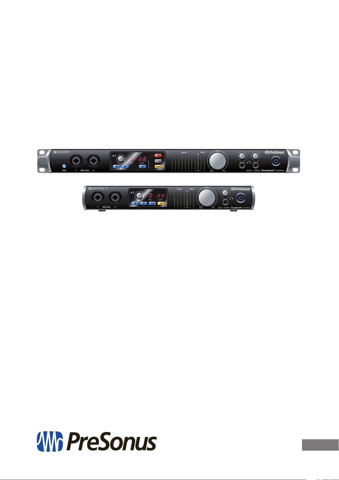
Quantum-series
Owner’s Manual
Thank you for purchasing a PreSonus Quantum-series Thunderbolt Audio Interface
and Studio Command Center. PreSonus Audio Electronics has designed Quantumseries interfaces utilizing high-grade components to ensure optimum performance
that will last a lifetime. Loaded with high-headroom, Class A, digitally controlled
XMAX™ microphone preamplifiers; an ultra-low latency Thunderbolt recording
and playback engine; talkback; monitor functions; and more, Quantum interfaces
break new boundaries for musical performances and productions. All you need is a
computer with a Thunderbolt connection, a few microphones and cables, powered
speakers, and your creativity, and you’re ready to record, mix, and release your music.
We encourage you to contact us with questions or comments regarding your
PreSonus Quantum interface. PreSonus Audio Electronics is committed to
constant product improvement, and we highly value your suggestions. We
believe the best way to achieve our goal of constant product improvement
is by listening to the real experts: our valued customers. We appreciate
the support you have shown us through the purchase of this product
and are confident that you will enjoy your Quantum interface!
About this manual: We suggest that you use this manual to familiarize yourself with
the features, applications, and correct connection procedures for your Quantum
interface before trying to connect it to your computer. This will help you avoid
problems during installation and setup. This manual covers the operation of both
the Quantum and Quantum 2. Whenever a functional difference is described,
the Quantum’s features will be called out first, followed by the Quantum 2.
Throughout this manual you will find Power User Tips that can quickly make you a
Quantum-series interface expert. In addition to the Power User Tips, you will find an
assortment of tutorials throughout this manual. These tutorials are designed to help
you get the most out of your Quantum interface and its suite of companion software.
1.2 Quantum-series Interface Hardware Features
• Pristine 24-bit audio up to 192 kHz
• Flawless analog signal path with top-quality 120 dB digital conversion
• 8/4 digitally controlled XMAX microphone preamps
• Preamp control from Studio One or UC Surface
• Simultaneous I/O up to 26/22 inputs and 32/24 outputs (8x14 / 4x6 at 192 kHz)
• 8/4 DC coupled balanced outputs for flexible monitoring
• 2/1 high-volume headphone amps with dedicated DACs
• Tight integration with Studio One version 3 for multitrack music production
• Compatible with most music software for Mac® and Windows®
• Stackable Thunderbolt Ports for clustering
1
1 Overview
1.3 UC Surface Features
1.3 UC Surface Features
UC Surface is a powerful monitor-mixing application that allows you to control your
Quantum preamps, talkback and monitoring functions.
• Remote control preamp level and 48V phantom power
• Remote control, talkback, dim, and mute
• Remote control over line input sensitivity
1.4 Studio One Artist Features
All PreSonus audio interfaces include PreSonus Studio One Artist recording software,
which comes with more than 4 GB of plug-ins, loops, and samples, giving you everything
you need for music recording and production. All monitor mixing and preamp control
functions for your Quantum-series interface are integrated into Studio One’s unique Cue
Mix feature. The Quick Start Guide in Section 6 of this manual will help you configure
your Quantum interface and provide you with a brief overview of Studio One’s features.
• Cue Mix provides complete integrated control over all Quantum functions
• Unlimited track count, inserts, and sends
• 20 high-quality, Native Effects™ plug-ins; amp modeling (Ampire XT), delay
(Analog Delay, Beat Delay), distortion (RedLightDist™), dynamics processing
(Channel Strip, Compressor, Gate, Expander, Fat Channel, Limiter, Tricomp™),
equalizer (Channel Strip, Fat Channel, Pro EQ), modulation (Autofilter, Chorus,
Flage, Phaser, X-Trem), reverb (Mixverb™, Room Reverb), and utility (Binaural Pan,
Mixtool, Phase Meter, Spectrum Meter, Tuner)
• More than 4 GB of loops, samples, and instruments, featuring: Presence™
XT virtual sample player, Impact virtual drum machine, SampleOne™ virtual
sampler, Mai Tai virtual polyphonic analog modeling synth, Mojito virtual analogmodeled subtractive synthesizer
• Innovative and intuitive MIDI mapping
• Powerful drag-and-drop functionality for faster workflow
• Available for macOS and Windows
Quantum-series
Owner’s Manual
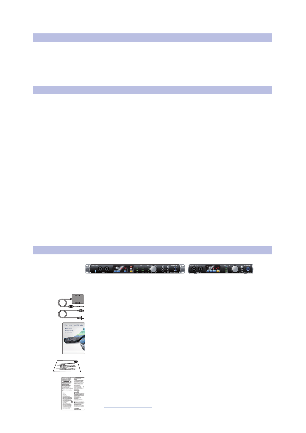
1.5 What is in the Box
You Quantum-series interface package contains the following:
PreSonus Quantum or Quantum 2 Thunderbolt Audio Interface
and Studio Command Center
External power supply
Studio One Key Commands Guide
Product registration and software authorization card
PreSonus Health Safety and Compliance Guide
Power User Tip: All companion software and drivers for your PreSonus Quantum-series
interface are available for download from your My PreSonus user account. Simply
visit http://my.presonus.com and register your Quantum-series interface to receive
downloads and licenses.
2
2 Hookup
2.1 Front Panel Connections and Controls
2 Hookup
2.1 Front Panel Connections and Controls
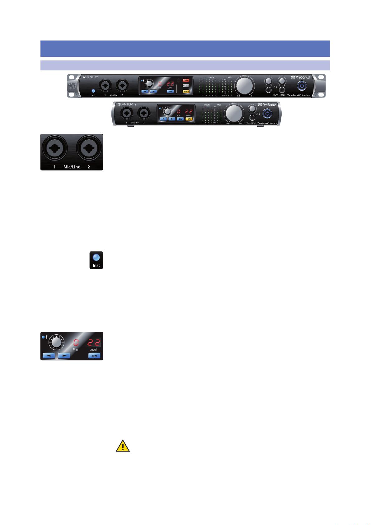
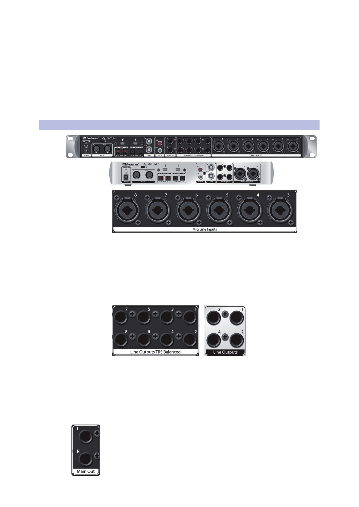
Microphone inputs. Your Quantum-series interface is equipped with 8/4 digitally
controlled PreSonus XMAX microphone preamplifiers for use with all types of
microphones. The XMAX design provides a Class A input buffer, followed by a
dual-servo gain stage. This arrangement results in ultra-low noise and wide gain
control, allowing you to boost signals without increasing noise. The ¼-inch front
panel inputs on Quantum can be either line or instrument. By default, they are set to
line. These inputs are not switching on the Quantum 2.
Each analog input on the Quantum-series interface features a combo jack. This
convenient connector accepts either a ¼-inch phone plug or an XLR plug. Mic Inputs
3-8/4 are located on the rear of the unit. Each input on your Quantum-series interface
is also auto-sensing. When an XLR is connected, the signal is routed to the preamp.
When a TRS is connected, the preamp is bypassed and the input signal is sent directly
to the ADC. When nothing is connected, Channels 1 and 2 on Quantum will default
to line inputs, Channel 3-8 will default to mic. All analog inputs on the Quantum 2
default to mic.
Instrument inputs. The ¼-inch TS connectors on Channels 1 and 2 are for use with
instruments (guitar, bass, etc.). When an instrument is plugged into the instrument
input, the mic preamp is bypassed, and the signal is routed to the instrument
preamplifier stage. Quantum users must engage the Inst button to use the
Instrument inputs.
Please note: As with any audio input device, plugging in a microphone or an instrument,
or turning phantom power on or off, will create a momentary spike in the audio output of
your Quantum-series interface. Because of this, we highly recommend that you turn
down the channel trim before changing connections or turning phantom power on or
off. This simple step will add years to life of your audio equipment.
Preamp controls. These controls allow you to adjust the gain and enable phantom
power for every onboard microphone and instrument preamp.
• Preamp Gain: Use this control to adjust the level of microphone preamps
1-8/4 and instrument preamps 1 and 2. The display to the far right will show the
current trim level. This encoder is also used to change from +4dbu to -10dbv
when a line-level TRS jack is connected.
• Next / Prev: Use these buttons to select the microphone preamp you wish to
control. The display to the right of the trim control will show which preamp is
currently being controlled.
• 48V: The Quantum-series interfaces provide 48V phantom power for each
microphone preamp. This feature can be individually enabled for each channel,
using this button. When 48V is active, the blue LED at the top of that channel’s
meters will illuminate.
Warning: Phantom power is only required for condenser microphones and
can severely damage dynamic mics, especially ribbon mics. Therefore, switch
phantom power off for all channels where it is not required.
XLR connector wiring for phantom power:
Pin 1 = GND Pin 2 = +48V Pin 3 = +48V
Quantum-series
Owner’s Manual
3
2 Hookup
2.1 Front Panel Connections and Controls
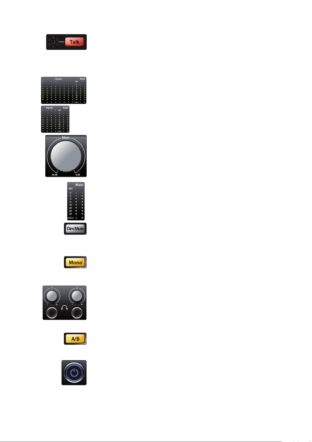
Talkback mic and controls (Quantum). Quantum features an onboard talkback
microphone. Press the Talk button to patch the signal to the selected mixes. To
control the level of the onboard Talkback mic, select the “c” (Comm) channel in the
preamp control section and use the encoder to adjust the level.
Power User Tip: Talkback routing for Quantum is handled inside your DAW. It will show
up as an input stream in your DAW I/O set-up.
Input meters. These eight-LED meters show the input level of the analog inputs on
your Quantum-series interface. The green LEDs will illuminate when the input signal
ranges from -50dBFS to -4dBFS. The yellow LEDs will illuminate when the input signal
reaches -2dBFS. The red Clip LED will illuminate when your input signal reaches
-0.5dBFS. At this level, the signal will begin to overload the analog-to-digital
converters and exhibit signs of clipping. Use the gain controls to keep the signal
below this level.
Main. The Main knob can control any or all of the outputs on the rear panel of your
Quantum and has a range of -80 dB to 0 dB. In addition to level control, the main
outputs have the following controls:
Quantum-series
Owner’s Manual
• Meters. These meters display the signal level received from Driver Returns 1 and
2 (Main Left/Right). These meters have the same range as the input meters (-50
dBFS to -0.5 dBFS) and are before the main output level.
• Dim / Mute (Quantum). This button controls both the Dim and Mute functions
for the Main Outputs. Press the button and release it to lower the outputs signal
by 20 dB. Press and hold the button to Mute the Main Output signal. The button
will illuminate yellow when Dim is active and red when Mute is active. These
functions are also available from within UC Surface and Studio One.
• Mono (Quantum). Press this button to sum the Main stereo output signal to
mono. The mono function is also available from within UC Surface and Studio One.
Power User Tip: Use the Mono feature to verify mono compatibility and to check for
phase cancellation in your stereo mixes.
Headphones. Your Quantum-series interface provides two/one headphone
output(s), each with its own level control. Each headphone output is provided with
its own unique output stream to route audio directly from your DAW (Quantum:
playback streams 11/12 and 13/14; Quantum 2: playback streams 5/6). These streams
are labeled as “Phones 1” and “Phones 2” in UC Surface. From UC Surface, any mix can
be routed to either headphone output. By default on Quantum, Headphone 1
mirrors the Main Output and Headphone 2 mirrors Output 1-2.
A/B (Quantum 2). The A/B button allows you to switch between two mixes. When
UC Surface is not accessed, this will toggle between the Headphone streams (5/6)
and the Main Mix streams (1/2). When UC Surface is active, you can choose the “B”
source from any mix pair.
Power button and Sync light. The lighted ring around the power button of your
Quantum is a clock source / sync indicator. It lets you know if you unit is receiving
word clock correctly.
• Blue. When this light is blue, your Quantum is correctly synced via Thunderbolt,
word clock, ADAT, or S/PDIF
• Flashing red and blue. Quantum is in the process of trying to sync to a received
clock signal.
4
2 Hookup
2.2 Back Panel Connections
• Red. Quantum is either not synced to your computer or its external clock source
• Flashing purple. The identify button is active in UC Surface.
2.2 Back Panel Connections
Quantum-series
Owner’s Manual
is not present.
Power User Tip: Word clock is the timing signal with which digital devices sync frame
rates. Proper word clock sync prevents digital devices from having pops, clicks, and
distortion in the audio signal due to mismatched digital audio transmission. In
general, you will use your Quantum-series interface as the master clock in your
studio; it provides high-quality word clock for this purpose. However, if you would
like to use another device as the master clock, you can set the input source for
clocking in UC Surface. See Section 4.1 for details.
Rear-panel Mic Inputs. As previously mentioned in Section 2.1, additional
microphone preamps are available on the rear of your Quantum interface.
Line Inputs. The ¼-inch TRS connectors on Channels 3-8/4 are for use with line-level
devices. These inputs are scaled to accept line-level signals up to +18 dBFS.
Power User Tip: When these inputs are engaged, the microphone preamp circuit is
bypassed completely, and no trim control is available. Typical examples of line-level
connections are synthesizer outputs, signal processors, and stand-alone mic preamps
and channel strips. Use the output level control on your line-level device to adjust its level.
Line Outputs. Quantum-series interfaces have 8/4 line balanced line outputs to
route to external devices, such as headphone amps, signal processors, and additional
monitors. Each output has an independent playback streams. Every line output is DC
coupled to provide control voltage to external analog equipment. This feature can be
used with any plug-in that supports it.
Power User Tip: The Main Level knob on the front of your Quantum-series interface can
be used to control any or all of these outputs. This is set from UC Surface. See Section 4.3
for more information.
Main Outs (Quantum). These are the main outputs for Quantum. The output level of
the Main Outputs is controlled by the Main level control on the front of the unit. Like
the eight line outputs, the main outputs have independent playback streams
(playback streams 1-2). Both Main Outputs are DC coupled to provide control voltage
to external analog equipment. This feature can be used with any pug-in that
supports it.
5
2 Hookup
2.2 Back Panel Connections
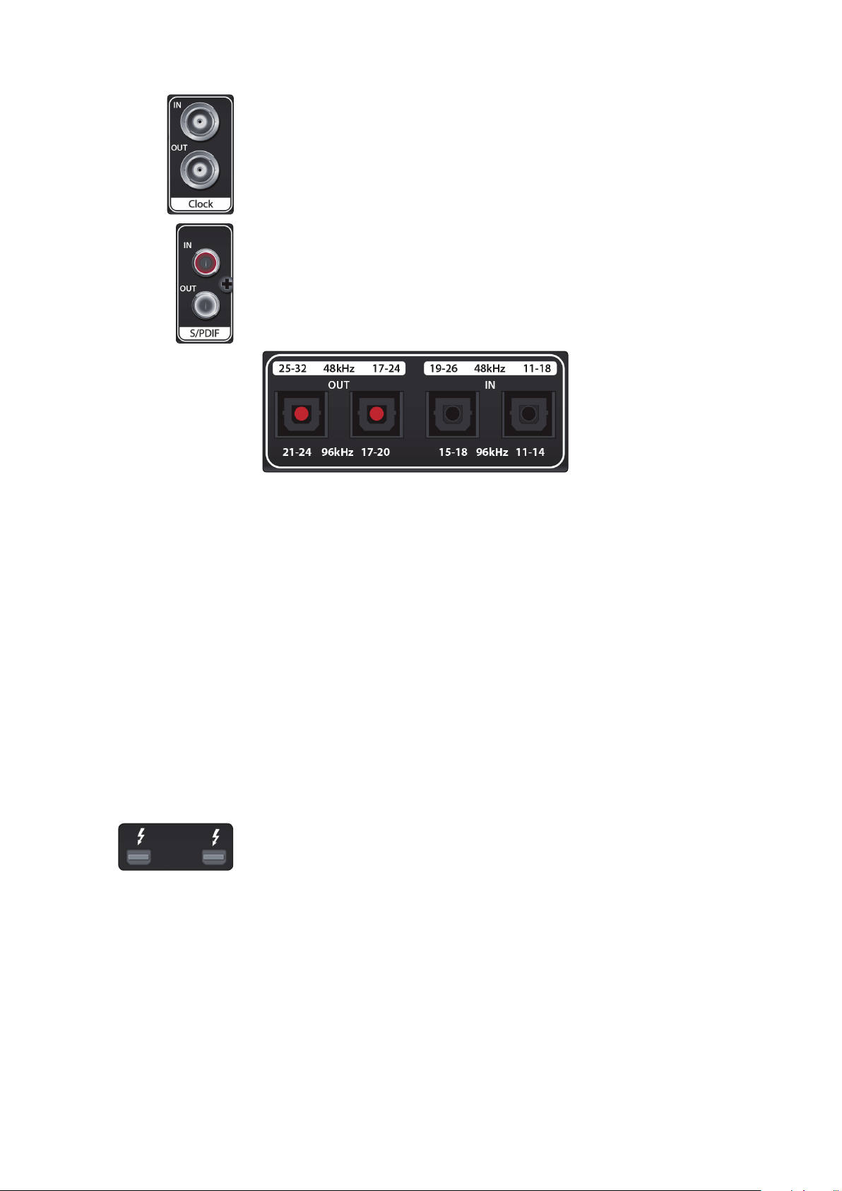
Clock In and Out. These BNC connections allow Quantum-series interfaces to
receive and transmit word clock to and from other digital audio devices.
Power User Tip: In UC Surface, when using the BNC Clock input, you will need to set “BNC”
as the Clock Source and set the sample rate to correspond to that of the external device.
See Section 4.1 for details. A 75Ω BNC word clock cable is required to achieve proper sync.
S/PDIF In and Out. The S/PDIF connections allow two channels of audio to be
transmitted and received at rates up to 24-bit, 96 kHz. The S/PDIF I/O also allows all
Quantum-series interfaces to send and receive word clock to external digital devices.
Power User Tip: In UC Surface, you will need to set “S/PDIF” as the Clock Source and the
sample rate to correspond to the external device when using an external S/PDIF device as
your master clock. See Section 4.1 for details.
Quantum-series
Owner’s Manual
ADAT – S/MUX In and Out. These are the ADAT – Dual S/MUX connections
for your external digital devices. When recording or playing back at 44.1
or 48 kHz, each ADAT I/O will provide 8 of the 16 available channels
consecutively, from left to right. When recording or playing back at 88.2 or
96 kHz, each connection will provide four of the available eight channels.
These inputs and outputs do not function at 176.4 or 192 kHz:
ADAT 1 Input ADAT 2 Input ADAT 1 Output ADAT 2 Output
44.1 / 48 kHz Channels 11-18 / 7-14 Channels 19-26 / 15-22 Channels 17-24 / 9-16 Channels 25-32 / 17-24
88.2 / 96 kHz Channels 11-14 / 7-10 Channels 15-18 / 11-14 Channels 17-20 / 9-12 Channels 21-24 / 13-16
When connecting a DigiMax DP88 to your Quantum interface, the ADAT
connections will also send and receive preamp control information for the DigiMax
DP88, so that it can be controlled directly from UC Surface or Studio One.
Power User Tip: In UC Surface, you will need to set “ADAT 1” as the Clock Source and the
sample rate to correspond to the external device when using an external ADAT device as
your master clock. See Section 4.1 for details. The ADAT 2 input cannot be used to receive
word clock.
Thunderbolt ports. Use these ports to connect your Quantum-series interface to
your computer. The second Thunderbolt port can be used to connect other
Thunderbolt devices to your computer.
Power User Tip: Your Quantum interface supports clustering over Thunderbolt. In
addition to allowing you to use your Quantum-series interface as a Thunderbolt hub, this
allows you to chain up to four Quantum interfaces, aggregated over Thunderbolt, for
higher I/O counts. See Section 5 for more information.
6

2 Hookup
Lock
Unlock
2.2 Back Panel Connections
MIDI I/O. These are the MIDI input and output connections. MIDI stands for “Musical
Instrument Digital Interface.” However, MIDI can be used for many things other than
instruments and sequencing. The MIDI inputs and outputs allow connection to a
variety of MIDI-equipped hardware, such as keyboard controllers, and can be used to
send and receive MIDI Machine Control and MIDI Time Code.
Note: MIDI does not carry audio signals but is frequently used to trigger or control an
audio source, such as a virtual instrument or hardware synthesizer. You should ensure
that MIDI data is correctly sent and received by the appropriate hardware or software.
You may also need to route hardware sound sources’ audio to the inputs of your
Quantum-series interface. Please consult the User’s Manual of your MIDI devices for
help with MIDI setup and usage.
Power Connection. This is where you connect the Quantum-series interface’s
external power supply. Your Quantum interface is equipped with a twist-lock power
connection, keep this in mind when connecting disconnecting it from your interface.
Quantum-series
Owner’s Manual
7
2 Hookup
345678
OUT
IN
L
R
IN
OUT
IN OUT
1234567
8
R
-
+
12V 5A
QUANTUM
R
19-26 48kHz 11-18
15-18
96kHz
11-14
25-32 48kHz 17-24
21-24
96kHz
17-20
IN
OUT
Clock S/PDIF Main Out Line Outputs TRS Balanced Mic/Line Inputs
MIDI
Power
INOUT
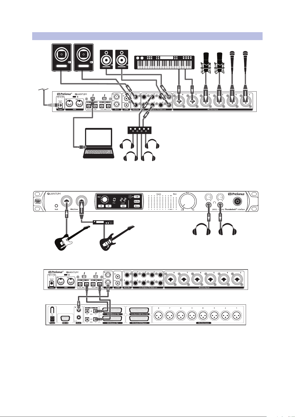
DigiMax-series preamps
or other compatible hardware
See www.presonus.com for
the latest system
requirements.
2.3 Quantum Hookup Diagram
2.3 Quantum Hookup Diagram
Quantum-series
Owner’s Manual
8
2 Hookup
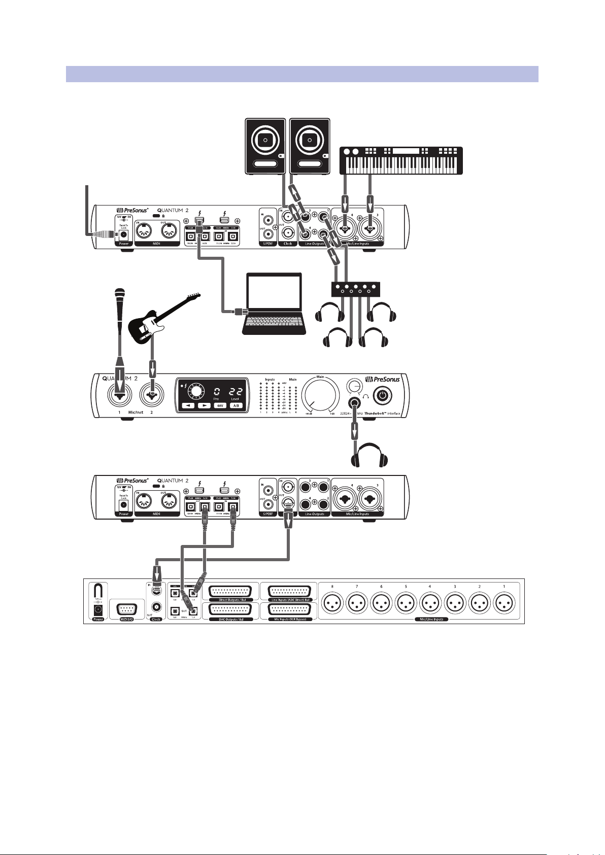
See www.presonus.com for
the latest system
requirements.
DigiMax-series preamps
or other compatible hardware
2.4 Quantum 2 Hookup Diagram
2.4 Quantum 2 Hookup Diagram
Quantum-series
Owner’s Manual
9

3 Connecting to a Computer
3.1 Installation for Windows and macOS
3 Connecting to a Computer
Your Quantum-series interface is loaded with professional audio tools and flexible
monitoring controls. Before connecting to a computer, please visit www.presonus.
com/products/Quantum/techspecs to verify the latest system requirements.
Note: The speed of your processor, amount of RAM, and capacity, size, and speed of your
hard drives will greatly affect the overall performance of your recording system. A faster
processor and more RAM can reduce signal latency (delay) and improve overall
performance.
The Universal Control installer for macOS and Windows is available for download
from your My PreSonus user account. This bundled installer includes Universal
Control, UC Surface, and the audio driver for Quantum-series interfaces. To begin,
you must first visit http://my.presonus.com, create or log into your user account, and
register your Quantum interface. Once registered, all software downloads will be
available from within your My PreSonus user account.
3.1 Installation for Windows and macOS
Connect your Quantum-series interface to an available Thunderbolt port and launch
the Universal Control installer. The installer will take you through each step of the
installation process. This application will install the macOS or Windows drivers as well
as UC Surface. Please read each message carefully.
It is recommended that you quit all applications before you start the installation.
The Universal Control installer will take you through each step of the installation
process.
Quantum-series
Owner’s Manual
3.2 Using a Quantum Interface with Popular Audio Applications
Complete setup instructions for Studio One Artist and a brief tutorial on its features
can be found in Section 6 of this manual. However, you can use your Quantum-series
interface with any audio-recording application that supports Core Audio or ASIO.
Please consult the documentation that came with your audio application for specific
instructions on how to select the Quantum-series interface driver as the audiodevice driver for your software.
Below are basic driver-setup instructions for a few popular audio applications.
Ableton Live
1. Launch Ableton Live.
2. Go to Options | Preferences | Audio.
3. Choose Driver Type: ASIO | Audio Device: ASIO PreSonus Quantum or Quantum
2.
4. Go to Input Config: Enable and select the desired Input channels.
5. Go to Output Config: Enable and select the desired Output channels.
Apple Logic
1. Launch Logic.
2. Go to Logic | Preferences | Audio.
3. Click on the Devices Tab.
4. On the Core Audio tab, check Enabled.
5. Select PreSonus Quantum or Quantum 2 from the device menu.
6. You will be asked if you’d like to relaunch Logic. Click try (re)launch.
10

3 Connecting to a Computer
3.2 Using a Quantum Interface with Popular Audio Applications
7. Your Quantum features custom I/O labels for faster workflow. To enable these
labels for use in Logic, go to Options | Audio | I/O Labels.
8. The second column in the pop-up window will be named Provided by Driver.
Activate each of these labels for your Quantum. When you are done, close this
window.
Avid Pro Tools 10+
1. Launch Pro Tools.
2. Go to Setup | Hardware and select Quantum or Quantum 2 from the Peripherals
list. Click OK.
3. Go to Setup | Playback Engine and select Quantum or Quantum 2 from the menu
at the top of the window. Click OK.
Cakewalk Sonar
1. Launch Sonar.
2. Go to Options | Audio... and click on the Advanced tab.
Quantum-series
Owner’s Manual
Steinberg Cubase
3. Change the Driver Mode to “ASIO.” (Note: Using WDM, rather than ASIO, for pro
audio applications is not recommended.)
4. Click the “OK” button.
5. Restart Sonar.
6. Go to Options | Audio... and click on the Drivers tab.
7. Highlight all input and output drivers beginning with “PreSonus Quantum” or
“PreSonus Quantum 2”
8. Go to Options | Audio... and click on the General tab.
9. Set the Playback Timing Master to “PreSonus Quantum... DAW Out 1” or
“PreSonus Quantum 2... DAW Out 1.”
10. Set the Recording Timing Master to “PreSonus Quantum... Mic/Inst 1” or
“PreSonus Quantum 2... Mic/Inst 1.”
1. Launch Cubase.
2. Go to Devices | Device Setup.
3. Select “VST Audio System” from the Devices column in the Device Setup.
4. Select PreSonus Quantum or Quantum 2 from the ASIO Driver dropdown list.
5. Click “Switch” to begin using the Quantum driver.
6. Once you have successfully changed the driver, go to Devices | VST Connections
to enable your input and output buses.
11
 Loading...