


S3.45
Strength-Training
Fitness Equipment
Assembly and Maintenance Guide

S3.45 Assembly and Maintenance Guide
Important Safety Instructions
Before beginning any fitness program, you should obtain a complete physical examination from your physician.
Il est conseillé de subir un examen médical complet avant d’entreprendre tout programme d’exercise. Si vous avez des étourdissements ou des faiblesses, arrêtez les exercices immédiatement.
When using exercise equipment, you should always take basic precautions, including the following:
•Read all instructions before using the S3.45 equipment. These instructions are written to ensure your safety and to protect the unit.
•Do not allow children on or near the equipment.
•Use the equipment only for its intended purpose as described in this guide. Do not use accessory attachments that are not recommended by the manufacturer: such attachments might cause injuries.
•Never operate the unit when it has been dropped or damaged. Return the equipment to a service center for examination and repair.
•Never drop or insert objects into any opening in the equipment. Keep hands away from moving parts.
•Always check the unit and its cables before each use. Make sure that all fasteners and cables are secure and in good working condition.
•Do not use the equipment outdoors.
Personal Safety During Assembly
•It is strongly recommended that a qualified dealer assemble the equipment. Assistance is required.
•Read each step in the assembly instructions and follow the steps in sequence. Do not skip ahead. If you skip ahead, you may learn later that you have to disassemble components and that you may have damaged the equipment.
•Assemble and operate the S3.45 on a solid, level surface. Locate the unit a few feet from walls or furniture to provide easy access.
Obtaining Service
Do not attempt to service the S3.45 yourself except for the maintenance tasks described in this guide. This unit does not contain any user-serviceable parts.
For information about product operation or service, check out the Precor web site at www.precor.com or contact an authorized Precor dealer or a Precor factory-authorized service company. To locate the dealer or service person nearest you, call 1-800-347-4404.
If you call or e-mail Customer Support, have the serial number and part numbers available.
You can find the serial number printed on a label on the chest press side of the Rear Upright. For future reference, write the serial number in the space below.
Serial number: _____________
•Wear proper exercise clothing and shoes for your workout—no loose clothing.
•Use care when getting on or off the unit.
•Do not overexert yourself or work to exhaustion.
The S3.45 is designed for your enjoyment. By following these precautions and using common sense, you will have many safe and pleasurable hours of healthful exercise with your new equipment.
•If you feel any pain or abnormal symptoms, stop your workout immediately and consult your physician.
IMPORTANT SAFETY INSTRUCTIONS
Important Safety Instructions
page 2

S3.45 Assembly and Maintenance Guide
Table of Contents
1
2
3
Important Safety Instructions ....................................................................... |
2 |
|
Personal Safety During Assembly ........................................................................................... |
2 |
|
Obtaining Service .................................................................................................................... |
2 |
|
Before You Begin ........................................................................................... |
5 |
|
Unpacking the Equipment ....................................................................................................... |
5 |
|
Optional Equipment ................................................................................................................. |
5 |
|
Preparations................................................................................................... |
6 |
|
Required Tools ......................................................................................................................... |
6 |
|
Installation Requirements ........................................................................................................ |
6 |
|
Assembly Tips ......................................................................................................................... |
6 |
|
Assembly Instructions .................................................................................. |
7 |
|
Open Boxes 1 and 2 ................................................................................................................ |
8 |
|
1. |
Attach Main Base.......................................................................................................... |
9 |
2. |
Attach Top Beam and Top Frame .................................................................................. |
10 |
3. |
Attach Front Upright ...................................................................................................... |
11 |
4. |
Attach Cross Brace ....................................................................................................... |
12 |
Open Box 3 ............................................................................................................................. |
13 |
|
5. |
Attach Seat Upright to Main Base ................................................................................. |
14 |
6. |
Attach Upright Flats ...................................................................................................... |
15 |
7. |
Attach Roller Pads ........................................................................................................ |
16 |
8. |
Assemble Preacher Curl Weight Stack ......................................................................... |
17 |
9. |
Assemble Leg Curl Weight Stack.................................................................................. |
18 |
10. |
Assemble Chest Press Weight Stack ............................................................................ |
19 |
11. |
Feed Lower Leg Curl Cable .......................................................................................... |
20 |
12. |
Feed Upper Leg Curl Cable .......................................................................................... |
22 |
13. |
Assemble Leg Curl Seat ............................................................................................... |
24 |
Table of Contents
page 3

S3.45 Assembly and Maintenance Guide
|
Open Box 4 ............................................................................................................................. |
26 |
||
|
|
14. |
Attach Chest Press Seat............................................................................................... |
27 |
|
|
15. |
Attach Press Arm Assembly ......................................................................................... |
28 |
|
|
16. |
Attach Handlebars ........................................................................................................ |
29 |
|
|
17. |
Assemble Chest Press Seat ......................................................................................... |
30 |
|
|
18. |
Feed Chest Press Cable ............................................................................................... |
31 |
|
Open Box 5 ............................................................................................................................. |
33 |
||
|
|
19. |
Attach Foot Support ...................................................................................................... |
34 |
|
|
20. |
Attach Seat Frame ........................................................................................................ |
35 |
|
|
21. |
Attach Row Bar Shelf and Seat Pads ........................................................................... |
36 |
|
|
22. |
Feed Upper Preacher Curl Cable ................................................................................. |
37 |
|
|
23. |
Feed Lower Preacher Curl Cable ................................................................................. |
39 |
|
|
24. |
Attach Lat Bar Holders.................................................................................................. |
41 |
|
|
25. |
Attach Accessories ....................................................................................................... |
42 |
|
|
26. |
Apply Weight Decals ..................................................................................................... |
43 |
|
Open Box 6 ............................................................................................................................. |
44 |
||
|
|
27. |
Attach Shrouds ............................................................................................................. |
45 |
4 |
Adjustments and Maintenance ..................................................................... |
47 |
||
1. |
Cable Adjustments ............................................................................................................. |
47 |
||
|
2. |
Selector Stem Adjustments ................................................................................................ |
48 |
|
|
|
Forward Angle Adjustment ................................................................................................. |
48 |
|
|
|
Backward Angle Adjustment .............................................................................................. |
49 |
|
|
|
Side-to-Side Vertical Adjustment ........................................................................................ |
50 |
|
|
3. |
Maintenance ...................................................................................................................... |
50 |
|
|
Warranty Registration .............................................................................................................. |
51 |
||
|
Warranty Card and Specifications .............................................................................. |
Back cover |
||
Table of Contents
page 4

S3.45 Assembly and Maintenance Guide
1Before You Begin
Thank you for purchasing the S3.45. This unit is part of the Pacific Fitness line of quality strength-training machines, which let you target specific muscle groups to achieve better muscle tone and overall body conditioning. To maximize your use of the equipment, please study this guide thoroughly.
Unpacking the Equipment
The S3.45 is carefully tested and inspected before shipment. Pacific Fitness ships the unit in several pieces that require assembly. Ask for assistance during the assembly process.
•Review the Installation Requirements found on the next page.
•When instructed to open a box, carefully unpack the pieces and lay them on the floor near the place where you plan to use the equipment.
Be careful to open boxes and assemble components in the sequence presented in this guide.
If any items are missing, contact the dealer from whom you purchased the unit or call 1-800-347-4404 for the dealer nearest you.
Optional Equipment
Optional equipment that you can purchase through your dealer includes the 750-lb Weight Stack and the Leg Press.
Note: If you have also purchased the Leg Press Option and are assembling it simultaneously, specific directions are included to reduce setup time.
Before You Begin
page 5
S3.45 Assembly and Maintenance Guide
2 Preparations
CAUTION: To set up this unit, you will need assistance. Do not attempt assembly by yourself.
You must review and follow the instructions in this guide. If you do not assemble and use the S3.45 according to these guidelines, you could void
the Pacific Fitness limited warranty (see back cover).
Required Tools
Tools that you must obtain before assembling the unit include:
⁄-inch socket wrench
¾-inch socket wrench
⁄-inch box-end wrench
¾-inch box-end wrench
Standard set of metric Allen wrenches
Two adjustable pliers or crescent wrenches
Measuring tape
Wire tie cutter (cuts plastic tie wraps)
Rubber mallet
Step stool
Installation Requirements
Follow these installation requirements when assembling the unit:
•Fill out and mail the limited warranty card. The warranty card is found on the back cover of this guide.
•Set up the S3.45 on a solid, flat surface. A smooth, flat surface under the unit helps keep it level. A level unit has fewer malfunctions.
•Provide ample space around the machine. Open space around the machine allows for easier access.
•Insert all bolts in the same direction. For aesthetic purposes, insert all the bolts in the same direction unless specified (in text or illustrations) to do otherwise.
•Leave room for adjustments. Tighten fasteners such as bolts, nuts, and screws so the unit is stable, but leave room for adjustments. Do not fully tighten fasteners until instructed in the assembly steps to do so.
Assembly Tips
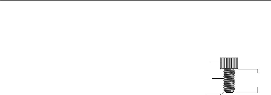
•A 6-inch scale is provided at the bottom of every assembly instruction page. Use this scale to identify the correct size bolts and spacers. The head of a bolt is not used in measuring the length of a bolt.
To find out the length of a particular bolt, measure its shank (the long, narrow part beneath the head). Refer to the following diagram:
Bolt head
Bolt threads |
To determine the |
length of a bolt, |
|
|
measure its shank. |
Shank
•Read all the caution notes on each page before completing that step.
Note: A few of the bolts used to assemble the S3.45 are longer than 6 inches. You may want to use a measuring tape to accurately identify the correct sizes.
•Some pieces have extra holes that you will not use. Use only those holes indicated in the instructions and illustrations.
•While you may be able to assemble the S3.45 using the illustrations only, important safety notes and other tips are included in the text.
Preparations
page 6

S3.45 Assembly and Maintenance Guide
3 AssemblyInstructions
Assembly of the S3.45 takes professional installers about 1.5 hours to complete. If this is the first time you have assembled this type of equipment, plan on significantly more time.
Professional installers are highly recommended!
However, if you acquire the appropriate tools, obtain assistance, and follow the assembly steps sequentially, the process will take time, but is fairly easy.
CAUTION: Obtain assistance! Do not attempt to assemble the S3.45 by yourself. Review the
Installation Requirements on page 6 before proceeding with the following steps.
The S3.45 comes in four boxes. (See the diagram at the right.)
Be careful to open boxes and assemble components in the sequence presented in this guide.
Note: With so many assembled parts, proper alignment and adjustment is critical. While tightening the nuts and bolts, be sure to leave room for adjustments. Do not fully tighten bolts until instructed to do so.
Box 5 |
|
Boxes 1 and 2 |
|
|
|
Preacher Curl |
|
Main Structure |
|
|
|
|
|
|
|
Box 4 |
|
|
|
|
|
Chest Press |
|
|
Box 3 |
|
|
|
|
|
Leg Curl |
|
|
|
|
1 |
2 |
3 |
4 |
5 |
6 |
Assembly Instructions
page 7

S3.45 Assembly and Maintenance Guide
Open Boxes 1 and 2
Use tie cutters to open the boxes.
The illustration shows how the S3.45 will look after you complete this section.
Note: Some items in these boxes may not be needed until later in the assembly process.
Important: Only use fasteners in bags labeled S3.45.
Discard all fasteners in bags labeled S3.25.
1 |
2 |
3 |
4 |
5 |
6 |
Open Boxes 1 and 2
page 8
S3.45 Assembly and Maintenance Guide
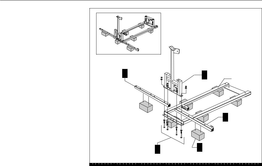
1. Attach Main Base
A.Place the Rear Upright on Weight Boxes with the flange side down.
B.Place the Chest Press Rear Base on the Rear Upright. Balance the other end on a Weight Box.
C.Place the Preacher Curl Rear Base on the Rear Upright. Balance the other end on a Weight Box.
D.Place the Main Base on the Chest Press Rear Base and Preacher Curl Rear Base.
E.Attach from underneath using four 3¼-inch bolts
eight washers four locknuts
F.Finger tighten all bolts, and then wrench tighten.
C |
Preacher Curl |
|
|
|
D Main Base |
|
Rear Base |
|
|
|
Rear Upright |
||
|
|
|
|
|
|
|
|
|
|
|
|
B |
Chest Press |
|
|
|
|
|
Rear Base |
|
|
|
4 |
- 3¼" bolts |
|
A Weight Box (6) |
|
|
|
E 8 |
- washers |
|
|
|
|
|
|
|
|
||
|
|
4 |
- locknuts |
|
|
|
1 |
2 |
3 |
4 |
5 |
6 |
|
Step 1. Attach Main Base
page 9

S3.45 Assembly and Maintenance Guide |
|
|
|
|
|
|
2. Attach Top Beam |
|
|
|
|
|
|
and Top Frame |
|
|
|
A Top Beam |
|
|
A. |
Place the Top Beam on the Rear Upright with |
|
|
|
B Top Frame |
|
|
windows facing down. Ensure the beam extends |
|
|
|
|
|
|
out as shown. |
|
|
|
|
|
B. |
Place the Top Frame on the Rear Upright and Top |
|
|
|
|
|
|
Beam. |
|
|
|
|
|
C. |
Attach from underneath using |
|
|
Rear |
|
|
|
four 3¼-inch bolts |
|
|
Upright |
|
|
|
eight washers |
|
|
|
|
|
|
four locknuts |
|
|
|
|
|
|
Finger tighten. |
|
|
|
|
|
D. |
Attach from the top using |
|
|
|
|
|
|
two 5¾-inch bolts |
|
|
|
|
|
|
four washers |
|
|
|
|
|
|
two locknuts |
|
|
|
|
4 - 3¼" bolts |
|
Finger tighten. |
|
|
|
|
C 8 - washers |
E. |
Wrench tighten all bolts. |
|
|
|
|
4 - locknuts |
|
|
|
|
|
||
F. |
With someone helping you, lift the structure into |
|
2 - 5¾" bolts |
|
|
|
|
D 4 - washers |
|
|
|
||
|
position. Place the structure where you intend to |
|
|
|
|
|
|
|
2 - locknuts |
|
|
|
|
|
keep it permanently. |
|
|
|
|
|
|
CAUTION: The frame may be unstable and may |
|
|
|
|
|
|
tip. To avoid this possibility, have an assistant |
|
|
|
|
|
|
hold the frame until the Seat Upright has been |
|
|
|
|
|
|
attached. |
|
|
|
|
|
G. |
Move the Weight Boxes out of the way until step 8. |
|
|
|
|
|
|
1 |
2 |
3 |
4 |
5 |
6 |
Step 2. Attach Top Beam and Top Frame
page 10
S3.45 Assembly and Maintenance Guide
3. Attach Front Upright
A.Attach the Front Upright to the Top Frame from the front using
one 4¾-inch bolt two washers one locknut Finger tighten.
Note: Placement of the Front Upright must match the illustration. The Shroud hole must
be offset toward the Preacher Curl Station.
B.Attach the Front Upright to the Main Base using two ¾-inch bolts
two washers Finger tighten.
C.Wrench tighten all bolts.
Top Frame
Shroud Hole
Front Upright
1 - 4¾" bolt A 2 - washers
1 - locknut
Preacher Curl Station will be on this side.
B 2 - ¾" bolts 2 - washers
Main Base
1 |
2 |
3 |
4 |
5 |
6 |
Step 3. Attach Front Upright
page 11

S3.45 Assembly and Maintenance Guide
4. Attach Cross Brace
A.Attach the Cross Brace to the Front Upright using two 3-inch bolts
four washers
two locknuts
B.Finger tighten. Do not wrench tighten until you attach the Seat Upright in step 5.
Front Upright
2 - 3" bolts A 4 - washers 2 - locknuts

 Top Frame
Cross Brace |
1 |
2 |
3 |
4 |
5 |
6 |
Step 4. Attach Cross Brace
page 12

S3.45 Assembly and Maintenance Guide
Open Box 3
Use tie cutters to open the box.
The diagram shows how the S3.45 will look after you complete this section.
Note: Some items in these boxes may not be used until later in the assembly process.
1 |
2 |
3 |
4 |
5 |
6 |
Open Box 3
page 13

S3.45 Assembly and Maintenance Guide
5. Attach Seat Upright to Main Base
A.Attach the Seat Upright to the Main Base using two 4-inch bolts
four washers two locknuts Finger tighten.
Note: If the holes do not line up easily, tilt the main structure back while another person puts a weight stem temporarily below the Main Base. Be sure to remove the weight stem after you wrench tighten.
B.Attach the Cross Brace to the Seat Upright using one 3-inch bolt
two washers one locknut Finger tighten.
C.Wrench tighten all bolts that connect the Cross Brace and the Seat Upright to the Main Base.
Front Upright
Cross Brace
Main Base
Seat Upright
Top Frame
1 - 3" bolt B 2 - washers
1 - locknut
2 - 4" bolts A 4 - washers 2 - locknuts
1 |
2 |
3 |
4 |
5 |
6 |
Step 5. Attach Seat Upright to Main Base
page 14

S3.45 Assembly and Maintenance Guide |
|
|
|
|
|
6. Attach Upright Flats |
|
|
|
|
|
A. Attach the Rotating Arm to the Upright Flats using |
|
|
|
|
|
two ¾-inch buttonhead bolts |
|
|
A 2 - ¾" buttonhead bolts |
|
|
Wrench tighten using the appropriate Allen |
|
|
|
|
|
|
|
|
|
|
|
wrench. |
|
|
|
|
|
B. Attach the Handles to the Seat Upright using |
|
|
|
|
|
two 3¼-inch bolts |
|
|
|
|
|
four washers |
Upright Flats |
|
|
|
|
two locknuts |
|
|
|
|
|
|
|
|
|
|
|
Wrench tighten with a box-end and socket wrench. |
|
|
|
|
|
|
|
|
|
|
Rotating Arm |
Handle |
|
|
|
|
|
|
|
|
Handle |
|
|
|
|
|
|
B |
2 - 3¼" bolts |
|
Seat Upright |
|
|
4 - washers |
|
|
|
|
|
|
2 - locknuts |
1 |
2 |
3 |
4 |
5 |
6 |
Step 6. Attach Upright Flats
page 15

S3.45 Assembly and Maintenance Guide
7. Attach Roller Pads
A.Insert the Leg Curl Roller Pad Rod.
B.Slide the Leg Curl Roller Pads on the Rod. Center the Pads on the Rod. Insert End Caps into the end of the Rod.
C.Secure the Rod in place from below using two hex set screws.
D.Repeat steps A through C for the Leg Extension Roller Rod.
Note: If you are assembling the Leg Press Option and the S3.45 simultaneously, please go now to Step 2 in the S3.45 Leg Press Option Assembly Instructions.
Leg Curl |
|
|
|
|
|
A Roller |
|
|
|
|
|
Pad Rod |
|
|
|
|
|
Leg |
|
|
|
|
|
D Extension |
|
|
|
|
|
Roller |
|
|
|
|
|
Pad Rod |
|
|
|
|
|
|
|
|
|
|
B |
|
|
C |
2 - hex set |
|
|
|
|
screws |
|
|
|
1 |
2 |
3 |
4 |
5 |
6 |
Step 7. Attach Roller Pads
page 16

S3.45 Assembly and Maintenance Guide |
|
|
|
|
|
|
|
|
8. Assemble Preacher Curl |
|
|
|
Top Frame |
|
|
|
|
Weight Stack |
|
|
|
|
|
|
|
|
Before assembling the Weight Stacks, be certain the |
|
|
|
|
|
|
|
|
S3.45 is positioned in its permanent location. |
|
|
|
|
|
|
|
|
A. |
Place two Guide Rods (from Box 1) into the large |
|
1 - 2¾" bolt |
|
|
|
|
|
|
holes on the Preacher Curl side of the Main Base. |
|
F 2 - washers |
Retainer |
Side Bracket |
|
|
|
|
The Guide Rods will be unstable until you |
|
1 - locknut |
Pins |
|
|
|
|
|
|
|
|
|
|
|
||
|
|
|
|
|
|
|
|
|
|
complete step 5. |
|
|
|
|
A Guide Rods (2) |
|
|
B. |
Place one Weight Cushion (from Box 1) on each |
|
|
|
|
|
||
|
Rear Upright |
|
|
|
|
|||
|
Guide Rod and allow it to slide down to the top of |
|
|
|
|
|
||
|
|
|
|
|
|
|
|
|
|
the Main Base. |
|
|
|
|
E Cap Plate |
|
|
C. |
Apply one tube of lubricant to each Guide Rod. |
|
|
|
|
|
|
|
|
Avoid getting lubricant on your clothing or on other |
|
|
|
|
|
|
|
|
parts of the machine. |
|
|
|
|
D |
|
|
D. |
Add the five 15-lb weights, the ten 10-lb weights, |
|
|
|
|
|
|
|
|
and the five 5-lb weights. Note the tab location for |
|
5 - 5-lb Weights |
|
|
|
|
|
|
weight stickers (you will attach the stickers later). |
|
|
|
|
|
|
|
|
Hold your finger over the plastic bushing in each |
|
|
|
|
|
|
|
|
weight to prevent the bushing from popping out. |
D |
10 - 10-lb Weights |
|
|
|
|
|
|
CAUTION: The weights are heavy! Handle |
|
|
|
|
|||
|
|
|
|
|
|
|
|
|
|
the weights carefully so as not to drop them |
|
|
|
|
|
|
|
|
or injure yourself. Pick up and place one weight |
|
|
|
|
|
|
|
|
at a time on the Guide Rods. Have someone |
|
5 - 15-lb Weights |
|
|
|
|
|
|
hold the Guide Rods in place while you slide |
|
|
|
|
|
|
|
|
|
|
|
|
|
|
|
|
|
the weights on the stack. |
|
|
|
|
|
C |
|
E. |
Place the Cap Plate on the Guide Rods with |
|
|
|
|
|
|
|
|
the hole facing toward you. Allow it to slide onto |
|
|
|
|
|
|
|
|
the Weight Stack. |
|
|
|
|
|
|
|
F. |
Insert the retainer pins of the Side Bracket into the |
|
|
|
|
|
|
|
|
Guide Rods. Attach the Side Bracket to the Top |
|
|
|
|
|
|
|
|
Frame using |
|
|
|
|
|
|
|
|
one 2¾-inch bolt |
|
|
|
|
B Weight |
|
|
|
two washers |
|
|
|
|
|
|
|
|
one locknut |
|
|
|
|
Cushions (2) |
|
|
|
|
1 |
2 |
3 |
4 |
5 |
6 |
|
|
Wrench tighten. |
|
||||||
Step 8. Assemble Preacher Curl Weight Stack
page 17
 Loading...