


POWERCLASS™ |
|
PC4200 / PC4400 / PC4800 / PC6600 OWNER’S MANUAL |
|
C O N T E N T S |
|
(click on a topic to view) |
|
•CONGRATULATIONS |
•QBASS / QBASS REMOTE |
•FEATURES / SPECIFICATIONS |
•CROSSOVER OPERATION |
•FEATURES / SPECIFICATIONS (cont.) |
•FREQUENCY DETENT CHARTS |
•INSTALLATION |
•INPUT COMBINE / GAIN |
•WIRING |
•THERMAL MANAGEMENT |
•WIRING (continued) |
•TROUBLE SHOOTING |
•POWER / GROUND |
•SYSTEM DIAGRAM ONE / TWO |
•POWER, GROUND, and REMOTE |
•SYSTEM DIAGRAM THREE |
•SPEAKER WIRING |
•SYSTEM DIAGRAM FOUR |
•BRIDGING |
•SYSTEM DIAGRAM FIVE |
•REAR ENDPLATE DIAGRAMS |
•SYSTEM DIAGRAM SIX |
•FRONT ENDPLATE PC4200 / PC4400 |
•BLOCK DIAGRAM 4200 / 4400 |
•FRONT ENDPLATE PC4800 |
•BLOCK DIAGRAM 4800 |
•FRONT ENDPLATE PC6600 |
•BLOCK DIAGRAM 6600 |
•INPUTS |
•WARRANTY |
Congratulations and thank you.....
for choosing PrecisionPower audio epuipment. At PrecisionPower we proudly design, engineer and manufacture audio products at our facility in Phoenix, Arizona. Our award winning engineering team utilizes innovative technology to consistently deliver Absolutely State of the ArtTM performance, sound quality, reliability, and value. This PrecisionPower product reflects our commitment to offer you unparalleled versatility and quality for years of dependable service and listening enjoyment.
S ervice
Do not attempt to service PrecisionPower products yourself. Performing exploratory surgery on your audio equipment yourself will void the warranty. Many parts of your PrecisionPower gear are custom built to our specifications. Our factory parts are not made available to anyone else nor are they for sale. Our goal
is to make sure that your PrecisionPower product will always sound as good as the day it was purchased. Contact your authorized PrecisionPower dealer about obtaining any warranty service through PrecisionPower.(See Warranty insde back cover)
F O R YO U R R E C O R D S :
M o d e l
Serial Number
Purchase Date
C aution!
The extended use of a high powered audio system may result in hearing loss or damage. While PrecisionPower systems are capable of "Concert Level" volumes with incredible accuracy, they are also designed for you to enjoy at more reasonable levels all of the sonic subtleties created by musicians. Please observe all local sound ordinances.
BACK TO CONTENTS
FEATURES / SPECIFICATIONS
Your new amplifier incorporates some or all of the following features: Adaptive MOSFET Switching Power Supply
Fully Complementary Darlington Output Stage
AP III Protection Circuitry (PC4200, PC4400, PC6800) AM IV Protection Circuitry (PC4800)
QBASS™ Bass Boost (PC4200, PC4400) QBASS PLUS™ (PC4800, PC6600)
QBASS REMOTE™ Compatible (PC4800, PC6600) PowerLock Speaker and Power Wire Connectors Detented, Variable 3-way Internal Crossover Non-Fading Sub Channel
Balanced Differential Input Stage
High Voltage Input Capability with Input Attenuation Switch Gold Plated RCA Input and Output Connectors
Mixed Mono/Stereo Operation
3 Year Warranty when installed by an Authorized PrecisionPower Dealer Completely Designed And Handcrafted In The USA
S p e c i f i c a t i o n s
Power Bandwidth: |
4.5 Hz - 100 kHz |
|
Total Harmonic Distortion: |
0.02 % |
|
Input Topology: |
|
Differential |
Input Sensitivity: |
150mv - 12 volts RMS |
|
Input Impedance: |
10k Ohms |
|
Load Impedance (stereo) |
2 - 8 Ohms |
|
Load Impedance (bridge) |
4 - 8 Ohms |
|
Supply Voltage |
|
11 - 15 volts |
Damping Factor |
>500 |
|
Slew Rate |
|
>50 V/μS |
Idle Current: |
|
PC4200 / PC4400 - 1.5 Amps |
|
|
PC4800 - 3.0 Amps |
|
|
PC6600 - 2.0 Amps |
C o n t i n u o u s O u t p u t P o w e r |
|
|
PC4200 |
|
PC6600 |
25 WRMS x 4 |
@ 4Ω per channel |
50 WRMS x 6 @ 4Ω per channel |
50 WRMS x 4 |
@ 2Ω per channel |
100 WRMS x 6 @ 2Ω per channel |
100 WRMS x 2 |
@ 4Ω bridged |
200 WRMS x 3 @ 4Ω bridged |
PC4400 |
|
PC4800 |
50 WRMS x 4 |
@ 4Ω per channel |
100 WRMS x 4 @ 4Ω per channel |
100 WRMS x 4 |
@ 2Ω per channel |
200 WRMS x 4 @ 2Ω per channel |
200 WRMS x 2 |
@ 4Ω bridged |
400 WRMS x 2 @ 4Ω bridged |
|
1 |
|
BACK TO CONTENTS
FEATURES / SPECIFICATIONS
QBASS™ and QBASS PLUS™ Specifications
QBASS™ (PC 4200, PC4400, and PC 6600)
Up to 12dB of Boost centered at 40Hz, with a Q-Factor of 2.
QBASS PLUS™ (PC 4800)
Up to 18dB of Boost with selectable center frequency at 30Hz, 36Hz, 44Hz or 60Hz. Selectable Q of 2 or 4. Optional remote mounted Boost Control. 
Optional QBASS REMOTE™ (PC 4800)
This boost control can be mounted in the dash and will supersede the
boost control on the amplifier endplate.
|
|
|
™ |
|
|
|
E |
|
|
|
OT |
|
|
M |
|
|
E |
|
|
|
R |
|
|
QBASS |
|
USA |
|
|
|
|
|
|
|
|
the |
|
|
|
in |
|
|
|
handcrafted |
|
|
|
and |
QBASS |
|
Designed |
|
|
|
|
|
Optional QPORT™ expansion module
allows one QBASS REMOTE™ to operate multiple amplifiers. Each
QPORT™ has outputs for four amplifiers as well as another QPORT™ for greater
expansion. See your authorized PrecisionPower
™
+18 
dealer for more information!
C r o s s o v e r S p e c i f i c a t i o n s
PC4200 / PC4400
Front - 12dB/Octave, Detented High Pass 20-5kHz
Rear - 12dB/Octave, Selectable Detented High or Low Pass 20-5kHz RCA Out-Summed Mono 24dB/Octave, Linkwitz-Riley Low Pass, 90Hz QBASS™ on Rear Channel
PC4800
Front - 12dB/Octave, Detented High Pass 20-5kHz
Rear - Choice of 12dB/Octave Detented High Pass 20-5kHz, or
Summed Mono 24dB/Octave, Linkwitz-Riley Detented Low Pass 44-315Hz RCA Outputs will be the opposite of your Rear Crossover choice.
QBASS PLUS™ on Rear Channel
PC6600
Front - 12dB/Octave, Detented High Pass 20-5kHz Rear - 12dB/Octave, Detented High Pass 20-5kHz
Sub-Summed Stereo 24dB/Octave, Linkwitz-Riley Low Pass at 90Hz QBASS PLUS™ on Sub Channel.
Dimensions
PC4200 |
|
|
PC4400 |
|
|
PC6600 |
|
|
PC4800 |
|
|
Length |
- |
12.22" |
Length |
- |
13.72" |
Length |
- 19.72" |
Length |
- |
23.72" |
|
Height |
- |
2.25" |
Height |
- |
2.25" |
Height |
- |
2.25" |
Height |
- |
2.25" |
Width |
- |
8.9" |
Width |
- |
8.9" |
Width |
- |
8.9" |
Width |
- |
8.9" |
|
|
|
|
|
2 |
|
|
|
|
|
|
BACK TO CONTENTS
INSTALLATION
Tools/Parts needed for Installation (not supplied)
Small flat blade screwdriver
Phillips Screwdriver (#2 or medium sized) Wire cutters
Wire strippers
4 - #6 round head screws, and 1 - #8 sheet metal screw (or nut, bolt, and star washer)
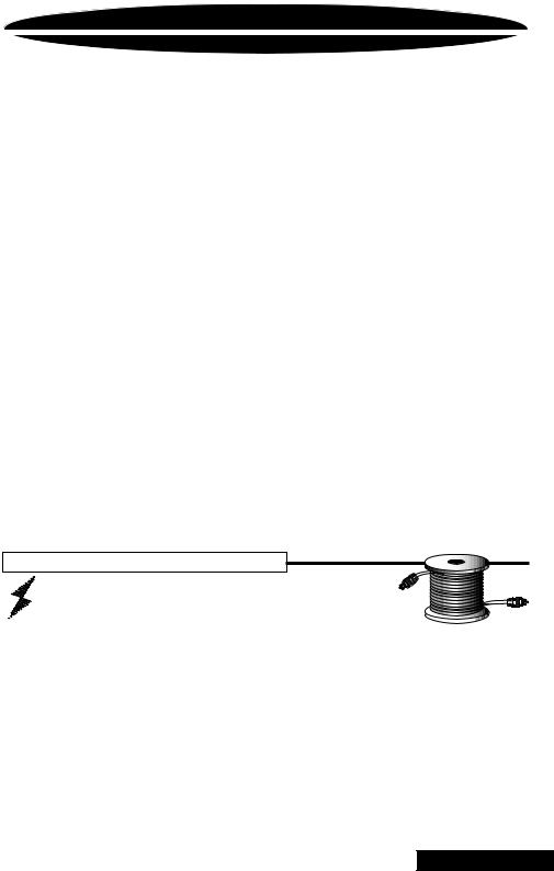
2 - Ring connectors (large enough to accommodate your method of grounding) In-line fuse or circuit breaker - see fuse chart below
Power and ground wire - see Power Wire Calculator on page 4 Speaker wire - 16 gauge or larger
Grommets (sized to work with the power wire you plan to use in your installation)
Tube of silicone sealant
F u s e r e q u i r e m e n t s
|
Amplifier |
Maximum Fuse Rating |
|
|
|
|
|||
|
|
|||
|
|
|
|
|
|
PC4200 |
40 |
Amp |
|
|
PC4400 |
60 |
Amp |
|
|
PC4800 |
80 |
Amp |
|
|
PC6600 |
80 Amp |
|
|
|
|
|
|
|
|
|
|
|
|
You will need to install an in-line fuse or circuit breaker in the power wire within 18" of the battery.This fuse or circuit breaker is to protect your vehicle from fire in case the power wire shorts to the vehicle body. If you are only using one amplifier, use the fuse rating indicated in this chart. If you are using more than one amplifier, add up the fuse ratings for all the amplifiers. This sum is the rating for your main fuse or circuit breaker. Use a power distribution block or fuse near your amplifiers with the appropriate fuse for each individual power wire.
3
BACK TO CONTENTS
WIRING
The following is a basic formula to be used as a guide to determine current draw. A 50% amplifier efficiency rating is used as an average. Your new POWERCLASS™ amplifier is more efficient, other amplifiers will probably be less. This formula is to be used as a guideline. Using wire of a larger gauge can only improve the current transfer of your system. Do not use smaller gauge wire.
Total RMS output x 2 = Total Input Wattage
Total Input Wattage = Current Draw (in Amps)
Supply Voltage
Example: A POWERCLASS™ 4400 amplifier has four channels at 50 watts RMS per channel into 4 Ohms (50 x 4 = 200). You would use the
formula in the following way:
200W x 2 = 400W
400W = 33.3A Total current draw.
12V
If the same amplifier is driven into a 2 Ohm stereo or 4 Ohm mono load, double it's 4 Ohm RMS rating. All POWERCLASS™ amplifiers will effectively double their power at this load.
100W x 4 x 2 = 800W
800W = 66.6A Total current draw.
12V
If you are using more than one amplifier, add up the total current draw for all of them and choose the appropriate gauge based on the grand total.
Po w e r W i r e C a l c u l a t o r
Recommended MINIMUM Gauge
Total Current Draw |
|
|
|
Length Of Wire To Be Run |
|
|
|
|
|||
|
|
|
|
|
|
|
|||||
|
( in Amps) |
Up to 4ft. |
4 to 7ft. |
7 to 10ft. |
10 to 13ft. |
13 to 16ft. |
16 to 19ft. |
19 to 22ft. |
22 to 28ft. |
|
|
|
|
||||||||||
|
0-20 |
14 |
12 |
12 |
10 |
10 |
8 |
8 |
|
8 |
|
|
20-35 |
12 |
10 |
8 |
8 |
6 |
6 |
6 |
|
4 |
|
|
35-50 |
10 |
8 |
8 |
6 |
6 |
4 |
4 |
|
4 |
|
|
50-65 |
8 |
8 |
6 |
4 |
4 |
4 |
4 |
|
2 |
|
|
65-85 |
6 |
6 |
4 |
4 |
2 |
2 |
2 |
|
0 |
|
|
85-105 |
6 |
6 |
4 |
2 |
2 |
2 |
2 |
|
0 |
|
|
105-125 |
4 |
4 |
4 |
2 |
2 |
0 |
0 |
|
0 |
|
|
125-150 |
2 |
2 |
2 |
2 |
0 |
0 |
0 |
|
00 |
|
|
|
|
|
|
|
|
|
|
|
|
|
|
|
|
|
|
|
|
|
|
|
|
|
NOTE: The ground wire should be the same gauge as the power wire.
4
BACK TO CONTENTS

WIRING
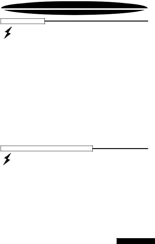
Before beginning, disconnect the negative (-) terminal of the battery prior to working on the positive (+) terminal to prevent a short to ground. This is important, unless you want to spend the rest of your life with a nickname like "Sparky," or "Smokey."
Reconnect the negative terminal only after all connections have been made.
Factory Ground wire may need to be replaced if it is frayed or broken.
Run signal cables (RCAs) and remote turn-on lead down the opposite side of the vehicle of the power wire to avoid radiated noise.
Avoid sharp edges that could chafe through the  insulation.
Positive
 Battery
Terminal
Fuse must be installed within 18" of battery
Trk 1 |
Drill a hole in the firewall and use a rubber grommet to keep wire from shorting.
Run the cables under the carpet near the side of the vehicle. Be careful not to drill or screw into the wires when you replace the trim.
For systems over 300 watts, add a ground cable from the amp to the battery
(see page 6).
Firmly attach Amp Ground Wire to solid metal (see page 6).
W a r n i n g !
Fuse must be installed within 18" of battery
5
BACK TO CONTENTS
POWER / GROUND
Grounding
Locate an area near the amplifier(s) that is metal and clean an area about the size of a quarter to bare metal. Inspect the area around and underneath to be sure you won't drill into wires, brake or fuel lines. Drill a pilot hole in the middle of this area. Terminate the ground wire with a ring connector and attach it to the bare metal using a #8 sheet metal screw and washer or preferably, a bolt, nut and a star washer (not supplied). We suggest crimping and soldering this connection. After the connection is complete, coat the area (on both sides) with silicone or some similar material to prevent rust from developing on the bare metal.
If your grand total current draw is over 50 amps (or total output power is over 300 watts), you should run a ground wire beside your power wire from the battery to the amplifier(s) in addition to your regular ground wire. Keep the ground and power wires
as close together as possible, and use the same gauge wire for both. This will ensure that you have a good ground path, and may eliminate such potential problems as engine noise and overheated amplifiers.
Charging System Considerations
If your grand total current draw is over 100 amps (or total output power is over 600 watts), you are probably exceeding the capability of your charging system. Dimming lights and fluctuating voltage are solid indicators that you need to upgrade your alternator, battery (or go to multiple batteries), or both.
Keep in mind that your amplifiers simply convert electrical energy to acoustical energy, and any electrical deficiency will compromise the performance of your sound system.
For more information about charging system upgrades, see your local authorized PrecisionPower Dealer or call the PrecisionPower technical support office at 1-800-62POWER.
6
BACK TO CONTENTS
POWER / GROUND and REMOTE
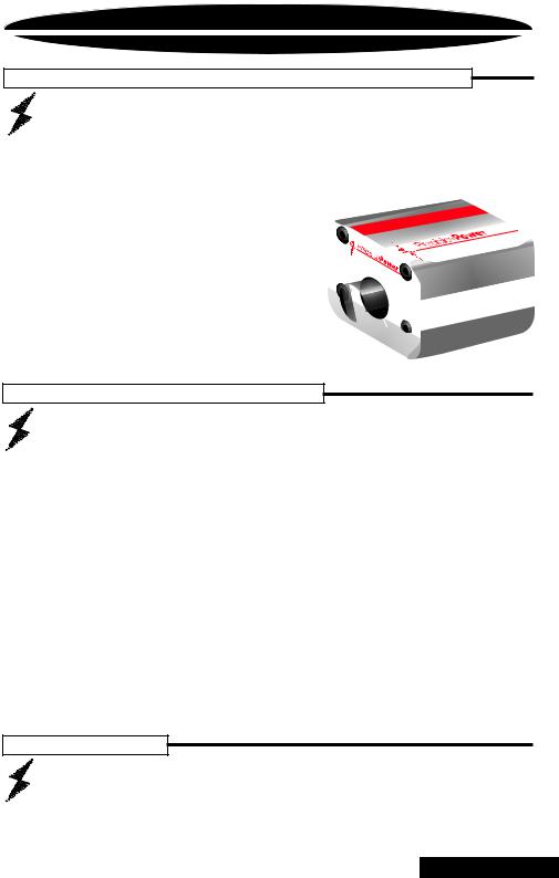
Once you have run both the power and ground wires, it's time to connect the cables to the amplifier. Cut off excess wire and, using wire strippers, strip the ends of the power and ground cables approximately 1/4 inch. Locate the PowerLock power and ground connector (supplied). With a small flat bladed screw driver, loosen the screws before attempting to insert the cables. Insert the wires into the appropriate hole, and tighten the screws. Once the wires are secure, the PowerLock may be plugged into the amplifier. The Power/Ground PowerLock will
accommodate 6 gauge wire for the PC4200 / PC4400, and 4 gauge wire for the PC4800 and PC6600.
Power/Ground PowerLock |
Fastening screws |
Power wires |
Connect to Amplifier |
R e m o t e t u r n - o n
Your head unit should have a lead marked 'remote' or 'power antenna' which will be used to turn on your amplifier. Extend this lead through your vehicle along with your RCA signal wires. Strip 1/4 inch of insulation off the wire and insert the end into the center terminal of the 5-pin speaker/remote PowerLock.
7
BACK TO CONTENTS
SPEAKER WIRING
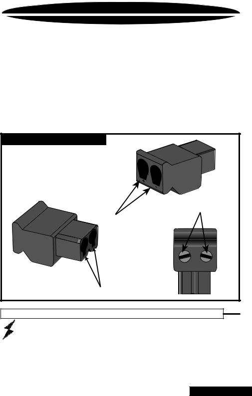
Using 16 gauge or larger, run the speaker wires from the amplifier location through the vehicle to the speakers. Observe the same precautions for routing these wires that you followed for running the power and remote turn-on wires. Cut off excess and, using wire strippers, strip 1/4 inch of insulation. Locate the speaker/remote turn-on PowerLock connector. Loosen the four outer screws on the underside of the connector and insert the front (PC4200, PC4400 and PC4800) or sub (PC6600) speaker leads into the end. Check to be sure you've maintained proper polarity before securing each wire.
Speaker PowerLock Connector 

Right Speaker negative 
Right Speaker positive 
Remote turn on 
Left Speaker positive 
Left Speaker negative 
Speaker PowerLock Connector 

Right Speaker negative 
Right Speaker positive 
Left Speaker positive 
Left Speaker negative 
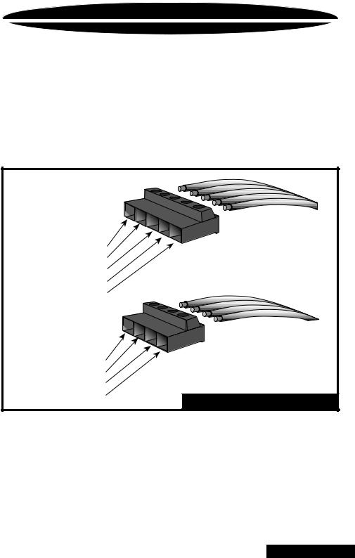
Speaker/Remote PowerLock |
For the rear channels, locate the four terminal speaker PowerLock connector. (For PC650, the front channel also uses a four terminal PowerLock connector.) On 4 and 6 channel PowerClass Amplifiers, all speaker PowerLocks plug into the amplifier with the screws facing up. Loosen the screws on the top of the blocks and insert the stripped ends of the speaker wires into the end. Double check polarity, secure each wire by tightening the screws, and plug the PowerLock connector into the amplifier with the screws on top.
8
BACK TO CONTENTS
 Loading...