


POWERCLASS™ |
|
PC2100 / PC2200 / PC2300 OWNER’S MANUAL |
|
C O N T E N T S |
|
(click on a topic to view) |
|
CONGRATULATIONS |
QBASS / CROSSOVER |
FEATURES / SPECIFICATIONS |
AMPLIFIER ADJUSTMENTS |
INSTALLATION |
TROUBLE SHOOTING |
WIRING |
SYSTEM DIAGRAM ONE |
WIRING (continued) |
SYSTEM DIAGRAM TWO |
POWER / GROUND |
SYSTEM DIAGRAM THREE |
SPEAKER WIRING |
SYSTEM DIAGRAM FOUR |
END PLATE DIAGRAM |
BLOCK DIAGRAM |
INPUTS |
WARRANTY |
Congratulations and thank you.....
for choosing PrecisionPower audio epuipment. At PrecisionPower we proudly design, engineer and manufacture audio products at our facility in Phoenix, Arizona. Our award winning engineering team utilizes innovative technology to consistently deliver Absolutely State of the ArtTM performance, sound quality, reliability, and value. This PrecisionPower product reflects our commitment to offer you unparalleled versatility and quality for years of dependable service and listening enjoyment.
S ervice
Do not attempt to service PrecisionPower products yourself. Performing exploratory surgery on your audio equipment yourself will void the warranty. Many parts of your PrecisionPower gear are custom built to our specifications. Our factory parts are not made available to anyone else nor are they for sale. Our goal
is to make sure that your PrecisionPower product will always sound as good as the day it was purchased. Contact your authorized PrecisionPower dealer about obtaining any warranty service through PrecisionPower.(See Warranty inside back cover)
F O R YO U R R E C O R D S :
M o d e l
Serial Number
Purchase Date
C aution!
The extended use of a high powered audio system may result in hearing loss or damage. While PrecisionPower systems are capable of "Concert Level" volumes with incredible accuracy, they are also designed for you to enjoy at more reasonable levels all of the sonic subtleties created by musicians. Please observe all local sound ordinances.
BACK TO CONTENTS

FEATURES / SPECIFICATIONS
Adaptive MOSFET Switching Power Supply
Fully Complimentary Darlington Output Stage AP III Protection Circuitry
QBASS™ Bass Boost
Two Way 90 Hz Crossover with Line Outputs Balanced Differential Input Stage
High Voltage Input Capability with Input Attenuation Switch Gold Plated RCA Input and Output Connectors PowerLock Speaker and Power Wire Connectors
Mixed Mono/Stereo Operation
Three Year Warranty when installed by an Authorized PrecisionPower Dealer Completely Designed And Handcrafted In The USA
S p e c i f i c a t i o n s |
|
Dimensions |
|
Power Bandwidth: |
4.5 Hz - 100 kHz |
||
Length - |
|||
Total Harmonic Distortion: |
0.02 % |
||
Input Topology: |
Balanced Differential |
PC2100 - 7.45" |
|
Input Sensitivity: |
120mv - 12 volts RMS |
PC2200 - 9.72" |
|
Input Impedance: |
10k Ohms |
PC2300 -11.72" |
|
Load Impedance (stereo) |
2 - 8 Ohms |
Height - |
|
Load Impedance (bridged) |
4 - 8 Ohms |
All - 2.25" |
|
Supply Voltage |
11 - 15 volts |
Width - |
|
Damping Factor |
>500 |
All - 8.9" |
|
Slew Rate |
>50 V/μS |
|
|
QBASS™ Equalization |
Up To +12dB Boost @ 40 Hz |
||
Idle Current: |
.7 Amps |
|
|
C r o s s o v e r S p e c i f i c a t i o n s
Crossover Point: 90 Hz
Choice of High Pass or Low Pass at RCA outputs while opposite is available at the Speaker Outputs.
PC2100 - Third Order (18 dB/octave), Butterworth alignment fixed at 90 Hz. PC2200/PC2300 - Fourth Order (24 dB/octave), Linkwitz-Riley alignment
fixed at 90 Hz.
C o n t i n u o u s O u t p u t Po w e r
PC2100
25 WRMS x 2 @ 4Ω per channel
50 WRMS x 2 @ 2Ω per channel
100 WRMS x 1 @ 4Ω bridged
PC2200
50 WRMS x 2 @ 4Ω per channel
100 WRMS x 2 @ 2Ω per channel
200 WRMS x 1 @ 4Ω bridged
PC2300
75 WRMS x 2 @ 4Ω per channel
150 WRMS x 2 @ 2Ω per channel
300 WRMS x 1 @ 4Ω bridged
1
BACK TO CONTENTS
INSTALLATION
Tools/Parts needed for Installation (not supplied)
Small flat blade screwdriver
Phillips Screwdriver (#2 or medium sized) Wire cutters
Wire strippers
4 - #6 round head screws, and 1 - #8 sheet metal screw (or nut, bolt, and star washer)
2 - Ring connectors (large enough to accommodate your method of grounding)
In-line fuse or circuit breaker - see fuse chart below
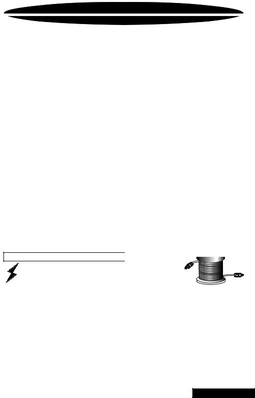
Power and ground wire - see Power Wire Calculator on page 3 Speaker wire - 16 gauge or larger
Grommets (sized to work with the power wire you plan to use in your installation)
Tube of silicone sealant
F u s e r e q u i r e m e n t s
|
Amplifier |
Maximum Fuse Rating |
|
|
|
|
|||
|
PC2100 |
20 |
Amp |
|
|
PC2200 |
30 |
Amp |
|
|
PC2300 |
35 |
Amp |
|
|
|
|
|
|
|
|
|
|
|
You will need to install an in-line fuse or circuit breaker in the power wire within 18" of the battery. This fuse or circuit breaker is to protect your vehicle from fire in case the power wire shorts to the vehicle body. If you are only using one amplifier, use the fuse rating indicated in this chart. If you are using more than one amplifier, add up the fuse ratings for all the amplifiers. This sum is the rating for your fuse or circuit breaker. You may also want to add a power distribution block near your amplifiers to keep the wiring tidy.
2
BACK TO CONTENTS
WIRING
The following is a basic formula to be used as a guide to determine amperage draw. A 50% amplifier efficiency rating is used as an average. Your new POWERCLASS™ amplifier is more efficient, other amplifiers will probably be less. This formula is to be used as a guideline. Using wire of a larger gauge can only improve the current transfer of your system. Do not use smaller gauge wire.
Total RMS output x 2 = Total Input Wattage
Total Input Wattage = Current Draw (in Amps)
Supply Voltage
Example: A POWERCLASS™ 2200 amplifier has two channels at 50 watts per channel RMS rating into 4 Ohms (50 + 50 = 100). You would use the formula in the following way:
100W x 2 = 200W
200W = 16.7A Total amperage draw.
12V
If the same amplifier is driven into a 2 Ohm stereo or 4 Ohm mono load, double its 4 Ohm RMS rating. All POWERCLASS™ amplifiers will effectively double their power at this load.
100W x 2 x 2 = 400W
400W = 33.3A Total amperage draw.
12V
If you are using more than one amplifier, add up the total amperage draw for all of them and choose the appropriate gauge based on the grand total.
P o w e r W i r e C a l c u l a t o r 


Recommended MINIMUM Gauge
Total Current Draw |
|
|
|
Length Of Wire To Be Run |
|
|
|
|
|||
|
|
|
|
|
|
|
|||||
|
( in Amps) |
Up to 4ft. |
4 to 7ft. |
7 to 10ft. |
10 to 13ft. |
13 to 16ft. |
16 to 19ft. |
19 to 22ft. |
22 to 28ft. |
|
|
|
|
||||||||||
|
0-20 |
14 |
12 |
12 |
10 |
10 |
8 |
8 |
|
8 |
|
|
20-35 |
12 |
10 |
8 |
8 |
6 |
6 |
6 |
|
4 |
|
|
35-50 |
10 |
8 |
8 |
6 |
6 |
4 |
4 |
|
4 |
|
|
50-65 |
8 |
8 |
6 |
4 |
4 |
4 |
4 |
|
2 |
|
|
65-85 |
6 |
6 |
4 |
4 |
2 |
2 |
2 |
|
0 |
|
|
85-105 |
6 |
6 |
4 |
2 |
2 |
2 |
2 |
|
0 |
|
|
105-125 |
4 |
4 |
4 |
2 |
2 |
0 |
0 |
|
0 |
|
|
125-150 |
2 |
2 |
2 |
2 |
0 |
0 |
0 |
|
00 |
|
|
|
|
|
|
|
|
|
|
|
|
|
|
|
|
|
|
|
|
|
|
|
|
|
NOTE: The ground wire should be the same gauge as the power wire.
3
BACK TO CONTENTS

WIRING
Before beginning, disconnect the negative (-) terminal of the battery prior to working on the positive (+) terminal to prevent a short to ground. This is important, unless you want to spend the rest of your life with a nickname like "Sparky," or "Smokey."
Reconnect the negative terminal only after all connections have been made.
Factory Ground wire may need to be replaced if it is frayed or broken.
Run signal cables (RCAs) and remote turn-on lead down the opposite side of the vehicle from the power wire to avoid radiated noise.
Avoid sharp edges that could chafe through the  insulation.
Positive
 Battery
Terminal
Fuse must be installed within 18" of battery
Trk 1 |
Drill a hole in the firewall and use a rubber grommet to keep wire from shorting.
Run the cables under the carpet near the side of the vehicle. Be careful not to drill or screw into the wires when you replace the trim.
Firmly attach Amp Ground Wire to solid metal (see page 5).
W a r n i n g !
Fuse must be installed within 18" of battery
4
BACK TO CONTENTS
 Loading...