


POWERCLASS™ |
|
PC2400 / PC2600 / PC21400 OWNER’S MANUAL |
|
C O N T E N T S |
|
(click on a topic to view) |
|
CONGRATULATIONS |
INPUTS |
FEATURES / SPECIFICATIONS |
CROSSOVER/GAIN CONTROL |
QBASS PLUS |
THERMAL MANAGEMENT |
INSTALLATION |
TROUBLE SHOOTING |
WIRING |
SYSTEM DIAGRAM ONE |
WIRING (continued) |
SYSTEM DIAGRAM TWO |
POWER / GROUND |
SYSTEM DIAGRAM THREE |
POWER, GROUND, and REMOTE |
SYSTEM DIAGRAM FOUR |
REAR ENDPLATE DIAGRAM |
BLOCK DIAGRAM |
FRONT ENDPLATE DIAGRAM |
ADDENDUM |
SPEAKER WIRING |
WARRANTY |
Congratulations and thank you.....
for choosing PrecisionPower audio epuipment. At PrecisionPower we proudly design, engineer and manufacture audio products at our facility in Phoenix, Arizona. Our award winning engineering team utilizes innovative technology to consistently deliver Absolutely State of the ArtTM performance, sound quality, reliability, and value. This PrecisionPower product reflects our commitment to offer you unparalleled versatility and quality for years of dependable service and listening enjoyment.
S ervice
Do not attempt to service PrecisionPower products yourself. Performing exploratory surgery on your audio equipment yourself will void the warranty. Many parts of your PrecisionPower gear are custom built to our specifications. Our factory parts are not made available to anyone else nor are they for sale. Our goal
is to make sure that your PrecisionPower product will always sound as good as the day it was purchased. Contact your authorized PrecisionPower dealer about obtaining any warranty service through PrecisionPower.(See Warranty insde back cover)
F O R YO U R R E C O R D S :
M o d e l
Serial Number
Purchase Date
C aution!
The extended use of a high powered audio system may result in hearing loss or damage. While PrecisionPower systems are capable of "Concert Level" volumes with incredible accuracy, they are also designed for you to enjoy at more reasonable levels all of the sonic subtleties created by musicians. Please observe all local sound ordinances.
BACK TO CONTENTS
FEATURES / SPECIFICATIONS
Adaptive MOSFET Switching Power Supply
Fully Complementary Triple Darlington Output Stage AM IV Protection Circuitry
QBASS PLUS™ Bass Boost QBASS REMOTE™ Compatible Advanced Buss Technology Forced Air Thermal Management
Two-Way 24dB/Octave Linkwitz-Riley 90Hz Crossover Crossover Line Outputs
Balanced Differential Input Stage
High Voltage Input Capability with Input Attenuation Switch Gold Plated RCA Input and Output Connectors PowerLock Speaker and Power Wire Connectors
Mixed Mono/Stereo Operation
Three Year Warranty when installed by an Authorized PrecisionPower Dealer Completely Designed and Handcrafted in the USA
S p e c i f i c a t i o n s
Power Bandwidth |
4.5 Hz - 100 kHz |
Total Harmonic Distortion |
0.02 % |
Input Topology |
Differential |
Input Sensitivity |
150mv - 12 volts RMS |
Input Impedance |
10 k Ohms |
Load Impedance (stereo) |
2 - 8 Ohms |
Load Impedance (bridged) |
4 - 8 Ohms |
Supply Voltage |
11 - 15 volts |
Damping Factor |
>500 |
Slew Rate |
>50 V/μS |
QBASS PLUS™ |
Up To +18dB Boost |
Frequency Centers |
30Hz, 36Hz, 44Hz and 60Hz |
Idle Current: |
PC2400 1.5 Amps |
|
PC2600 2 Amps |
|
PC21400 3 Amps |
Crossover |
Two Way, 24dB/Octave Linkwitz-Riley |
Crossover Frequency |
90Hz |
C o n t i n u o u s O u t p u t Po w e r |
Dimensions |
||
PC2400 |
|
|
|
100 WRMS x 2 @ 4Ω per channel |
Length - |
15.75" |
|
200 WRMS x 2 @ 2Ω per channel |
Height |
- |
2.25" |
400 WRMS x 1 @ 4Ω bridged |
Width |
- |
8.9" |
PC2600 |
|
|
|
150 WRMS x 2 @ 4Ω per channel |
Length - |
17.75" |
|
300 WRMS x 2 @ 2Ω per channel |
Height |
- |
2.25" |
600 WRMS x 1 @ 4Ω bridged |
Width |
- |
8.9" |
PC21400 |
|
|
|
350 WRMS x 2 @ 4Ω per channel |
Length - |
25.25" |
|
700 WRMS x 2 @ 2Ω per channel |
Height |
- |
2.25" |
1400 WRMS x 1 @ 4Ω bridged |
Width |
- |
8.9" |
1
BACK TO CONTENTS
QBASS PLUS™
QBASS PLUS™
On PC2400, PC2600 and PC21400 amplifiers, we've taken bass control to a higher level with QBASS PLUS™ .
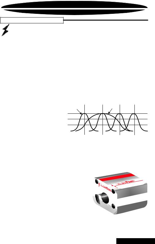
The two QBASS switches (labeled 1 and 2) on the front end of the amplifier allow you to select one of four frequency centers - 30Hz, 36Hz, 44Hz and 60Hz. The Q
SELECT switch determines the width of boosted frequencies. A 'Q' of 2 (switch out) will give you a wide boost while a 'Q' of 4 will boost a narrow range of frequencies (See chart below). On the rear end panel you will find the QBASS™ level control and the plug-in for an optional QBASS REMOTE™ dash mounted level control. Adjust the level control clockwise for up to 18dB of boost at your selected frequency and Q.
|
|
|
|
|
|
QBASS PLUS™ |
|
|
Q B A S S ™ |
Settings |
|
Q = 4 |
|
Q = 2 |
|
||
1 |
2 |
|
Freq. |
+18dB |
|
|
|
|
IN |
IN |
|
30Hz |
+12dB |
|
|
|
|
IN |
OUT |
|
36Hz |
+6dB |
|
|
|
|
OUT |
IN |
|
44Hz |
|
|
|
|
|
|
0dB |
|
|
|
|
|||
OUT |
OUT |
|
60Hz |
|
|
|
|
|
|
|
|
|
|
||||
|
|
|
|
|
|
|||
|
|
|
|
|
30Hz |
36Hz |
44Hz |
60Hz |
CAUTION: QBASS PLUS™ should only be used in systems with strong subwoofers. 18dB is a lot of bass boost and could damage full range speakers.
Optional QBASS REMOTE™ |
|
|
|
|
This boost control can be mounted |
|
|
|
E |
|
|
|
|
™ |
dash and will supersede the boost |
|
|
|
OT |
QBASS |
M |
|||
|
|
E |
|
|
|
|
R |
|
|
control on the endplate. |
|
|
|
USA |
|
|
|
and |
|
|
|
|
|
the |
|
|
|
|
in |
|
|
|
|
handcrafted |
|
QBASS |
|
Designed |
|
Optional QPORT™ expansion |
|
|
|
|
™ |
|
|
|
|
module allows one boost control |
|
|
|
|
to operate multiple amplifiers. Each |
+18 |
|
|
|
QPORT™ has outputs for four amplifiers as well as another QPORT™ for greater
expansion. See your Authorized PrecisionPower
Dealer for more information!
2
BACK TO CONTENTS
INSTALLATION
Tools/Parts needed for Installation (not supplied)
Small flat blade screwdriver
Phillips Screwdriver (#2 or medium sized) Wire cutters
Wire strippers
4 - #6 round head screws, and 1 - #8 sheet metal screw (or nut, bolt, and star washer)
2 - Ring connectors (large enough to accommodate your method of grounding)
In-line fuse or circuit breaker - see fuse chart below
Power and ground wire - see Power Wire Calculator on page 3 Speaker wire - 16 gauge or larger
Grommets (sized to work with the power wire you plan to use in your installation)
Tube of silicone sealant
F u s e r e q u i r e m e n t s
|
Amplifier |
Maximum Fuse Rating |
|
|
|
|
|||
|
PC2400 |
60 |
Amp |
|
|
PC2600 |
80 |
Amp |
|
|
PC21400 |
160 Amp |
|
|
|
|
|
|
|
|
|
|
|
|
You will need to install an in-line fuse or circuit breaker in the power wire within 18" of the battery. This fuse or circuit breaker is to protect your vehicle from fire in case the power wire shorts to the vehicle body. If you are only using one amplifier, use the fuse rating indicated in this chart. If you are using more than one amplifier, add up the fuse ratings for all the amplifiers. This sum is the rating for your fuse or circuit breaker. You may also want to add a power distribution block near your amplifiers to keep the wiring tidy.
3
BACK TO CONTENTS
WIRING
The following is a basic formula to be used as a guide to determine current draw. A 50% amplifier efficiency rating is used as an average. Your new POWERCLASS™ amplifier is more efficient, other amplifiers will probably be less. This formula is to be used as a guideline. Using wire of a larger gauge can only improve the current transfer of your system. Do not use smaller gauge wire.
Total RMS output x 2 = Total Input Wattage
Total Input Wattage = Current Draw (in Amps)
Supply Voltage
Example: A POWERCLASS™ 2600 amplifier has two channels at 150 watts per channel RMS rating into 4 Ohms (150 x 2 = 300). You would use the formula in the following way:
300W x 2 = 600W
600W = 50A Total current draw.
12V
If the same amplifier is driven into a 2 Ohm stereo or 4 Ohm mono load, double it's 4 Ohm RMS rating. All POWERCLASS™ amplifiers will effectively double their power at this load.
300W x 2 x 2 = 1200W
1200W = 100A Total current draw.
12V
If you are using more than one amplifier, add up the total current draw for all of them and choose the appropriate gauge based on the grand total.
Po w e r W i r e C a l c u l a t o r 


Recommended MINIMUM Gauge
Total Current Draw |
|
|
|
Length Of Wire To Be Run |
|
|
|
|
|||
|
|
|
|
|
|
|
|||||
|
( in Amps) |
Up to 4ft. |
4 to 7ft. |
7 to 10ft. |
10 to 13ft. |
13 to 16ft. |
16 to 19ft. |
19 to 22ft. |
22 to 28ft. |
|
|
|
|
||||||||||
|
0-20 |
14 |
12 |
12 |
10 |
10 |
8 |
8 |
|
8 |
|
|
20-35 |
12 |
10 |
8 |
8 |
6 |
6 |
6 |
|
4 |
|
|
35-50 |
10 |
8 |
8 |
6 |
6 |
4 |
4 |
|
4 |
|
|
50-65 |
8 |
8 |
6 |
4 |
4 |
4 |
4 |
|
2 |
|
|
65-85 |
6 |
6 |
4 |
4 |
2 |
2 |
2 |
|
0 |
|
|
85-105 |
6 |
6 |
4 |
2 |
2 |
2 |
2 |
|
0 |
|
|
105-125 |
4 |
4 |
4 |
2 |
2 |
0 |
0 |
|
0 |
|
|
125-150 |
2 |
2 |
2 |
2 |
0 |
0 |
0 |
|
00 |
|
|
|
|
|
|
|
|
|
|
|
|
|
|
|
|
|
|
|
|
|
|
|
|
|
NOTE: The ground wire should be the same gauge as the power wire.
4
BACK TO CONTENTS

WIRING
Before beginning, disconnect the negative (-) terminal of the battery prior to working on the positive (+) terminal to prevent a short to ground. This is important, unless you want to spend the rest of your life with a nickname like "Sparky," or "Smokey."
Reconnect the negative terminal only after all connections have been made.
W a r n i n g ! |
Fuse must be installed within 18" of battery
5
BACK TO CONTENTS
 Loading...