

Page 1
Control Concepts
Model 1029C
Po w er Co ntrol System
Instruction Manu al
(952) 949-9009 Fax (952) 949-9559
Another quality product from:
7128 Shady Oak Road
Eden Prairie, MN 55344 USA
www.researchinc.com
Page 2
CONTROL
CONCEPTS
INC.
INSTALLATION MANUAL
MODEL 1029C
7870 PARK DRIVE
CHANHASSEN, MN 55317
(952) 474-6200
1-800-765-2799
FAX (952) 474-6070
www.ccipower.com
Page 3

CONTROL CONCEPTS, INC. 2 YEAR LIMITED WARRANTY
CONTROL CONCEPTS, INC. warrants that the products delivered will be as described in the sales order or contract.
CONTROL CONCEPTS, INC. warrants to the original user that CONTROL CONCEPTS, INC. products will be free from
defects in materials and workmanship for a period of two (2) years after the date CONTROL CONCEPTS, INC. ships
such products.
If any CONTROL CONCEPTS, INC. product is found to be defective in material or workmanship during the applicable
warranty period, CONTROL CONCEPTS, INC.’s entire liability, and purchasers sole and exclusive remedy, shall be the
repair or replacement of the defective product at CONTROL CONCEPTS, INC.’s election. CONTROL CONCEPTS,
INC. shall not be liable for any costs or expenses, whether direct or indirect, associated with the installation, removal or
re-installation of any defective product. All shipping and freight costs are the responsibility of the customer. CONTROL
CONCEPTS, INC.’s limited warranty shall not be effective or actionable unless there is compliance with all installation
and operating instructions furnished by CONTROL CONCEPTS, INC., or if the products have been modified or altered
without the written consent of CONTROL CONCEPTS, INC., or if such products have been subject to accident, misuse,
mishandling, tampering, negligence or improper maintenance. Any warranty claim must be submitted to CONTROL
CONCEPTS, INC. in writing within the stated warranty period.
CONTROL CONCEPTS, INC.’s limited warranty is made in lieu of, and CONTROL CONCEPTS, INC. disclaims all other
warranties, whether expressed or implied, including but not limited to any IMPLIED WARRANTY OF MERCHANTABILITY,
ANY IMPLIED WARRANTY OF FITNESS FOR A PARTICULAR PURPOSE, any implied warranty arising out of a course
of dealing or of performance, custom or usage of trade.
CONTROL CONCEPTS, INC. SHALL NOT, UNDER ANY CIRCUMSTANCES BE LIABLE FOR ANY DIRECT, INDIRECT,
INCIDENTAL, SPECIAL OR CONSEQUENTIAL DAMAGES (INCLUDING, BUT NOT LIMITED TO, LOSS OF PROFITS,
REVENUE OR BUSINESS) OR DAMAGE OR INJURY TO PERSONS OR PROPERTY IN ANY WAY RELATED TO
THE MANUFACTURE OR THE USE OF ITS PRODUCTS. The exclusion applies regardless of whether such damages
are sought based on breach of warranty, breach of contract, negligence, strict in tort, or any other legal theory, even if
CONTROL CONCEPTS, INC. has notice of the possibility of such damages.
By purchasing CONTROL CONCEPTS, INC.’s products, the purchaser agrees to the terms and conditions of this limited
warranty.
WARNING: The Control Concepts, Inc. power controllers use power thyristors to switch voltage to the connected
load. Line voltage must be assumed at the output terminals at all times, even when the control signal has been
removed and the load voltage appears to be off. It has been mandated by the National Electrical Code and the
Occupational Safety and Heath Act of 1970 that a physical disconnect be opened ahead of all remotely actuated
controls before performing any maintenance work on the controller or its connected load.
PROPRIETARY DATA
© Copyright 2007, Control Concepts, Inc. Chanhassen, MN 55317
The information and design disclosed herein are the property of Control Concepts, Inc. and may not be used,
reproduced or disclosed in any form except as granted in writing by:
CONTROL CONCEPTS, INC
7870 PARK DRIVE
CHANHASSEN, MN 55317
PHONE: (952) 474-6200
TOLL FREE: (800) 765-2799
FAX: (952) 474-6070
www.ccipower.com
Page 4
MODEL 1027 TABLE OF CONTENTS
DESCRIPTION 1
FEATURES 1
SPECIFICATIONS 2
INSTALLATION 4
INSTALLATION DRAWINGS 5
COMMAND CONNECTIONS 8
POWER CONNECTIONS 12
FEEDBACK SELECTION 13
START-UP 13
ADJUSTMENTS 14
TROUBLESHOOTING 16
MANUFACTURED BY 16
REPLACEMENT PARTS 17
MODEL NUMBER IDENTIFICATION 18
THEORY OF OPERATION 19
50 to 750 AMPS
LISTED 3L32 FILE No: E136219
INDUSTRIAL CONTROL EQUIPMENT
NOTE: THE 1000 AMP UNIT IS NOT UL LISTED
MODEL 1029C i 10/19/2007
Page 5

DESCRIPTION
MODEL COVERED:
This manual describes the Control Concepts model 1029C controller with the following ratings:
CURRENT: 50 Amps to 750 Amps.
VOLTAGE: 120 Vac to 575 Vac. @ 50/60 Hz.
GENERAL DESCRIPTION:
The model 1029C is a single-phase, phase-angle power controller that has selectable feedback, dual command signals,
adjustable current limiting & over-current trip, shorted SCR detection, estimated output voltage metering and output
current metering.
FEATURES
CURRENT LIMITING:
A user adjustable setting prevents the load current from exceeding a presettable value. This feature is useful where
variable resistance loads have a heavy current draw as they are warming up.
OVER CURRENT TRIP:
If the SCR current exceeds this preset value, a relay with form C contacts is energized, an LED is lighted and the SCR's
are prevented from turning on. This provides a means to initiate an alarm or to remove system power in the event that
excessive current occurs. Momentary closure of a remote switch or momentary interruption of main power will reset the
O.C.T. circuit.
SOFT START AND MISSING CYCLE DETECTION:
The output voltage is ramped from zero to the desired output at a ramp rate equivalent to a time constant of 0.2 seconds
on power interuptions of 1/2 cycle or more. This feature minimizes inrush currents when controlling variable resistance
loads or inductive coupled loads.
SHORTED SCR DETECTION:
A relay with form C contacts and an LED is energized in the event an SCR fails in the ON state. This provides a means to
initiate an alarm or to remove system power in the event an SCR fails in the "ON" state.
STATUS INDICATORS:
Command - Intensity of command indicator is proportional to the command signal and the “ON” time of the SCRs.
Load - The intensity of the load indicator is proportional to the load current.
Shorted SCR - When “ON”, an SCR has failed in the shorted mode.
Over Current Trip - When “ON” indicates that load current has exceeded the preset Over Current Trip level.
RUN OR IDLE INPUT SELECTION:
With this feature, either of two command signals can be selected by a remote switch. This allows the controller to be
conveniently switched from a "RUN" to an "IDLE" state, or from an "AUTOMATIC" to a "MANUAL" control.
CHOICE OF FEEDBACK:
The Average value of the load voltage, the RMS value of the load voltage or the RMS value of the load current can
be linearly controlled with respect to the command signal. The power (watts) applied to the load can also be linearly
controlled with respect to the command signal. (Power feedback is an option that must be factory installed.) The controller
will also accept external feedback signals of 0/5 Vdc or 100 uA representing other process parameters.
OUTPUT METERING:
A filtered 0/5 Vdc signal representing the load voltage and a 0/5 Vdc signal representing the load current are provided for
remote monitoring.
MODEL 1029C 1 10/19/2007
Page 6
SPECIFICATIONS
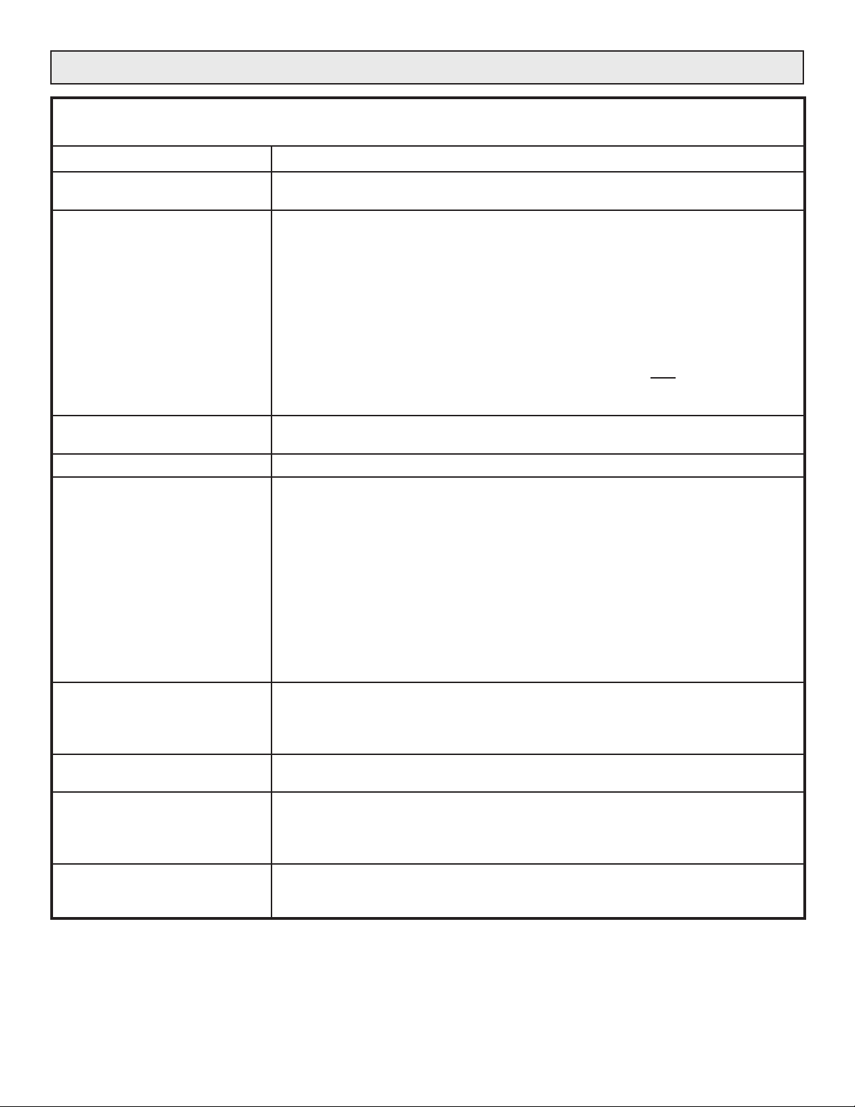
The following specifications apply over an ambient temperature of 0 to 55ºC and a supply voltage of 85% to 110% of the
nominal supply voltage rating.
CONTROL MODE: Single phase SCR phase-angle control.
FRAME SIZE: The “[AMPS]A” term within the model number specifies the maximum continuous
RMS current rating at the maximum operating ambient temperature of 55ºC.
RUN COMMAND SIGNAL
AND/OR
IDLE COMMAND SIGNAL:
OPERATING VOLTAGE: The control transformer installed in this controller has three selectable voltages;
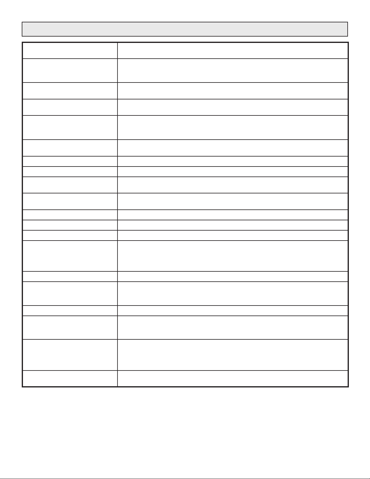
SCR RATINGS: Peak forward and reverse voltage 1600 volts
SCR SURGE CURRENT
RATINGS :
(peak one cycle
non-repetitive
I
@ 125°C)
TSM
SCR PROTECTION: dV/dT rating = 200 volts/microsecond.
RUN/IDLE CONTROL: A contact closure selects either the run command signal input or the idle command
ELECTRICAL CONNECTIONS:
# of LUGS PER LINE/LOAD
CONNECTIONS
ELECTRICAL ISOLATION: 50-160 Amp heatsink to supply and load voltage: 2500 Volts Peak
Command signal Input Impedance
1/5mA 1200 ohms
4/20mA 300 ohms
0-5Vdc 200K ohms
Potentiometer 200K ohms
(1K, 1/4watt pot recommended for optimum linearity, up to 20K permissible)
The control circuit supplies 5 Vdc to the potentiometer.
Other command signal ranges may be available.
Check with factory for special applications.
If it is desired to use a current command in both the run and idle command
input, the signals must be common sourcing or they must be isolated from
one another. Contact factory for more information.
240, 480 & 575 Vac. Other voltages are be available - contact factory for details.
Controller Rating Surge Current Rating
50 & 80 Amp: 1750 Amps Peak
120 Amp: 1900 Amps Peak
160 Amp: 4000 Amps Peak
200 Amp: 4500 Amps Peak
250 Amp: 5200 Amps Peak
300 Amp: 7000 Amps Peak
380 Amp: 10,000 Amps Peak
425 Amp: 13,000 Amps Peak
500 Amp: 10,000 Amps Peak
600 Amp: 13,000 Amps Peak
750 Amp: 16,500 Amps Peak
dV/dT circuit consists of a capacitor in series with a noninductive resistor. This circuit
is in parallel with the SCRs. The SCRs are protected from voltage transients by a
Metal Oxide Varistor.
signal input. See Figure 10.
Connectors for line and load are provided for copper wire from 6 ga to 250MCM on
controllers rated 50 to 425 Amps.
Connectors for line and load are provided for copper wire from 1/0 to 500MCM on
controllers rated 500 to 750 Amps.
200-750 Amp heatsinks are at line voltage potential.
Command signal to supply and load voltage: 1500 Volts Peak
MODEL 1029C 2 10/19/2007
Page 7
SPECIFICATIONS (Continued)
ZERO AND SPAN: Potentiometers on the circuit board allow zero and span adjustments of ± 25% of
span for run and idle and are factory calibrated.
CURRENT LIMITING: A potentiometer on the circuit board allows adjustment of the current limit setting
from 20% to 105% of the controller rating. (The current limit potentiometer is factory
set for 105% of the rated current unless otherwise specified.)
VOLTAGE METER OUTPUT: A filtered metering signal equals 5.0 Vdc when the nominal line voltage is applied to
the load. Metering load = 5mA max.
CURRENT METER OUTPUT: A filtered metering signal equals 5.0 Vdc when the frame rating current is applied to
the load. Metering load = 5mA max.
GATE DRIVE: An optical coupled current source of 250mA with a minimum compliance of 10 volts
provides the gate drives to the SCRs. Duration or "back porch" is approximately 1.4
milliseconds (60 electrical degrees).
VOLTAGE COMPENSATION: When using voltage feedback, the load voltage remains constant, independent of
supply voltage changes within + 10%, -15%.
POWER DISSIPATION: 1.5 Watts per amp of load current.
CERTIFICATION: Model 1029C, 120 - 575 Volts, 50 - 750 Amps, is U.L. listed. U.L. File No. E136219.
INTERNAL FEEDBACK AVG: User has choice of: True RMS Voltage, or True RMS Current. Power feedback can
be factory installed if desired. Only one type of feedback may be selected.
EXTERNAL FEEDBACK: An external 0 to 5Vdc or 0 to 50uA signal, (derived from the load,) may be used for
external feedback into the controller. See Figure 19 for connections.
LINEARITY: The controlled variable is linear within 2% of Span with respect to command signal.
COMMAND INDICATOR: This green LED indicates that the gate drive is present.
LOAD CURRENT INDICATOR: The intensity of this green LED is proportional to the load current.
OVER CURRENT TRIP
INDICATOR:
SHORTED SCR INDICATOR: This red LED, when lighted, indicates a shorted SCR.
O.C.T. & SHORTED SCR
RELAY CONTACT RATINGS:
CONTROL RANGE: 0 to 98% of supply voltage.
ENVIRONMENT: Operating temperature 0ºC to 55ºC (32ºF to 132ºF)
PHYSICAL: 50 & 80 Amp controllers 16 pounds
LINE 2 REQUIREMENTS: The Line 2 connection is the return for the internal control transformer rated at 50
This amber LED, when lighted, indicates the over current limit has been exceeded
and the Over Current Trip relay has been energized. The SCR's will be prevented
from turning on while this circuit is active. Reset by closure between Pins 9 & 10 or
momentary power interruption. See Figure 7.
The Over Current Trip, and the Shorted SCR circuits, each control a relay which
has form C contacts rated for 5 Amps @ 120Vac. The contacts are available on the
command connector. See Figure 7.
Storage temperature: -40ºC to 80ºC (-40ºF to 176ºF)
Humidity: 0 to 95%, non-condensing
120 & 160 Amp controllers 17 Pounds
200 to 425 Amp controllers 21 Pounds
500 to 750 Amp controllers 40 Pounds
VA. # 18 ga wire.
MODEL 1029C 3 10/19/2007
Page 8
INSTALLATION
TRANSFORMER TAP:
Open lid and locate power transformer. Check voltage tap
is on desired line voltage.
MOUNTING AND LOCATION:
Mount controllers on a vertical surface with the fins
oriented so that air may flow vertically between them. For
controllers with fans (excludes the 50 & 80 amp units) may
be mounted in any direction.
COMMAND INPUTS:
The 1029C has two command inputs (RUN and IDLE)
which are selected by a contact closure. A potentiometer,
a DC voltage or a DC current may be used as a command
signal into either input. These connections are made to the
command connector as described below.
Run/Idle:
A remote switch can be used, as shown in Figure 10, to
cause the controller to be controlled by either the run or idle
inputs. Connecting terminal 10 (COM) to terminal 11 (RUN/
IDLE) on the command connector causes the run signal
input to be in control. Opening the connection between
terminal 10 and terminal 11 causes the idle signal input to
be in control.
COMMAND SIGNAL OPTIONS
Voltage:
A 0 to 5 Vdc signal may be used as the command signal
by connecting the positive signal to terminal 13 (run), or
terminal 15 (idle). Always connect negative (common)
signal to terminal 14 (common). See Figure 9 or Figure 11.
Potentiometer:
A 1k ohm to 20k ohm potentiometer, 1/4 watt or more, may
be used to adjust the load voltage. (A 1k ohm potentiometer
provides the maximum linearity.) See Figure 8 or Figure 10.
Consult factory for other options.
POWER & SAFETY CONNECTIONS
Over Current Trip Relay:
Connections to the form C contacts of the over current
relay are shown in Figure 7. The contacts are rated for 5
Amps at 120 Vac and are intended for activating an alarm
and/or removing power from the system by operating a
contactor or a circuit breaker.
Over Current Trip Reset:
Momentary closure of a switch connected between
terminals 9 and 10 on the command connector will reset
the over current relay and will release the SCRs from the
locked off state. The reset switch can also be used as an
on off control. Closure of the switch causes the SCRs to be
immediately turned OFF. When the switch is opened, the
SCRs begin operation at zero conduction angle and slew at
the soft start rate to the desired output. The Over Current
Trip circuit may also be reset by a momentary interruption
of supply power.
Shorted SCR Relay:
Connections to the 5 Amp 120 Vac form C contacts are
shown in Figure 7. This relay energizes if an SCR fails
in the shorted mode and is intended to activate an alarm
and/or cause power to be removed from the system by
operating a contactor or a circuit breaker.
Current:
Connect positive current connection to terminal 13 (run)
or terminal 15 (idle). Connect negative or return current
connection to terminal 14 (common). See Figure 9 or
Figure 11.
When using a current command in both the run and
idle command input, they must either be sourcing, or be
isolated from one another. Contact factory for details.
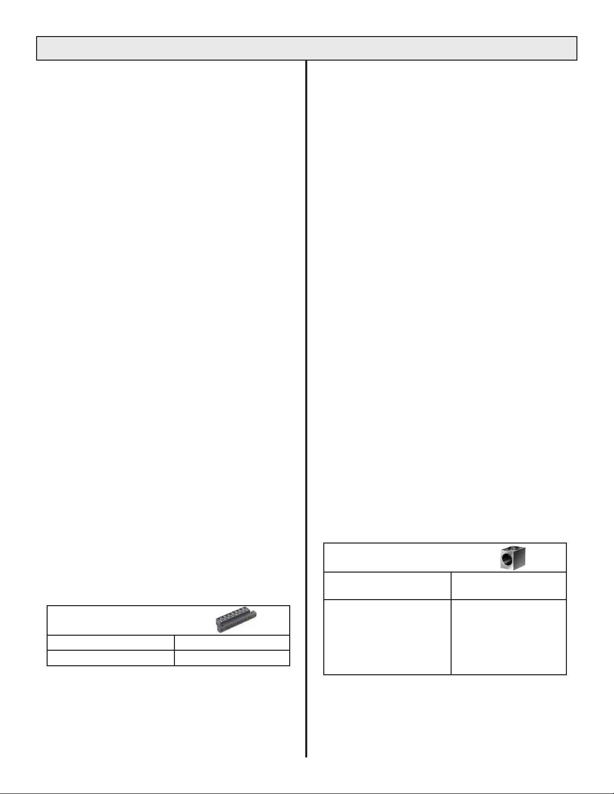
RECOMMENDED TIGHTENING TORQUE
FOR EDGE CARD CONNECTOR:
WIRE SIZE (AWG) TORQUE
14 TO 26GA 4.4 - 5.5 IN-LBS
Power Connections:
Figure 15 & Figure 16 show typical electrical connections.
The LINE 1 and LOAD 1 connectors are approved for wire
sizes from 6ga to 500 MCM.
ECOMMENDED TIGHTENING TORQUE
R
FOR THE LINE AND LOAD CONNECTORS
WIRE SIZE (AWG) OR
CIRCULAR MILLS
4 TO 6GA
1 TO 2GA
1/0 TO 2/0GA
3/0 TO 4/0GA
250 TO 350MCM
500MCM
:
TORQUE
100 IN-LBS
125 IN-LBS
150 IN-LBS
200 IN-LBS
250 IN-LBS
300 IN-LBS
MODEL 1029C 4 10/19/2007
Page 9
INSTALLATION DRAWINGS
7.65
6.65
0.50
LINE 1
GROUND
LOAD
LINE 2
1.125
)
6
10.6
10.
8.27
10.0
0.288 X 0.50 (2
0.60
0.29 (2)
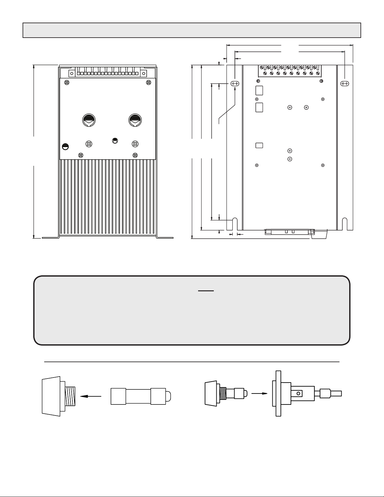
Figure 1. Installation drawing for 50, 80, 120 & 160 Amp units.
NOTE: THE 50 and 80 AMP UNITS ARE NOT FAN COOLED. THEY MUST BE
MOUNTED ON A VERTICAL SURFACE WITH THE FINS ORIENTED VERTICALLY
SO THAT AIR MAY FLOW FREELY BETWEEN THE FINS.
120 and 160 AMP UNITS ARE FORCED AIR COOLED.
THEY MAY BE MOUNTED IN ANY DIRECTION.
Figure 2.
ORIENTATION OF FUSE IN HOLDER
Fuse makes contact only when correctly installed.
Place flat end of fuse in cap, then insert into holder.
MODEL 1029C 5 10/19/2007
Page 10
INSTALLATION DRAWINGS (Continued)
00
17.40
5.
4.00
10.85
LOAD
LINE
18
W
)
. METER
FB. BK.
I. METER
V
IDLE (+) W
RUN (+
COM(-) CCW
DANGER
HIGH VOLTAGE
COMMAND
LOAD
CW
+5V
SHORTED
1234567891011121314151617
TED
SHOR
CURRENT
Y
R
LA
SC
OVER
RELAY
RE
CURRENT
OVER
RESET
COMMON
RUN/IDLE
SCR
INDICATOR
INDICATOR
16.00
5/16 Dia. (4)
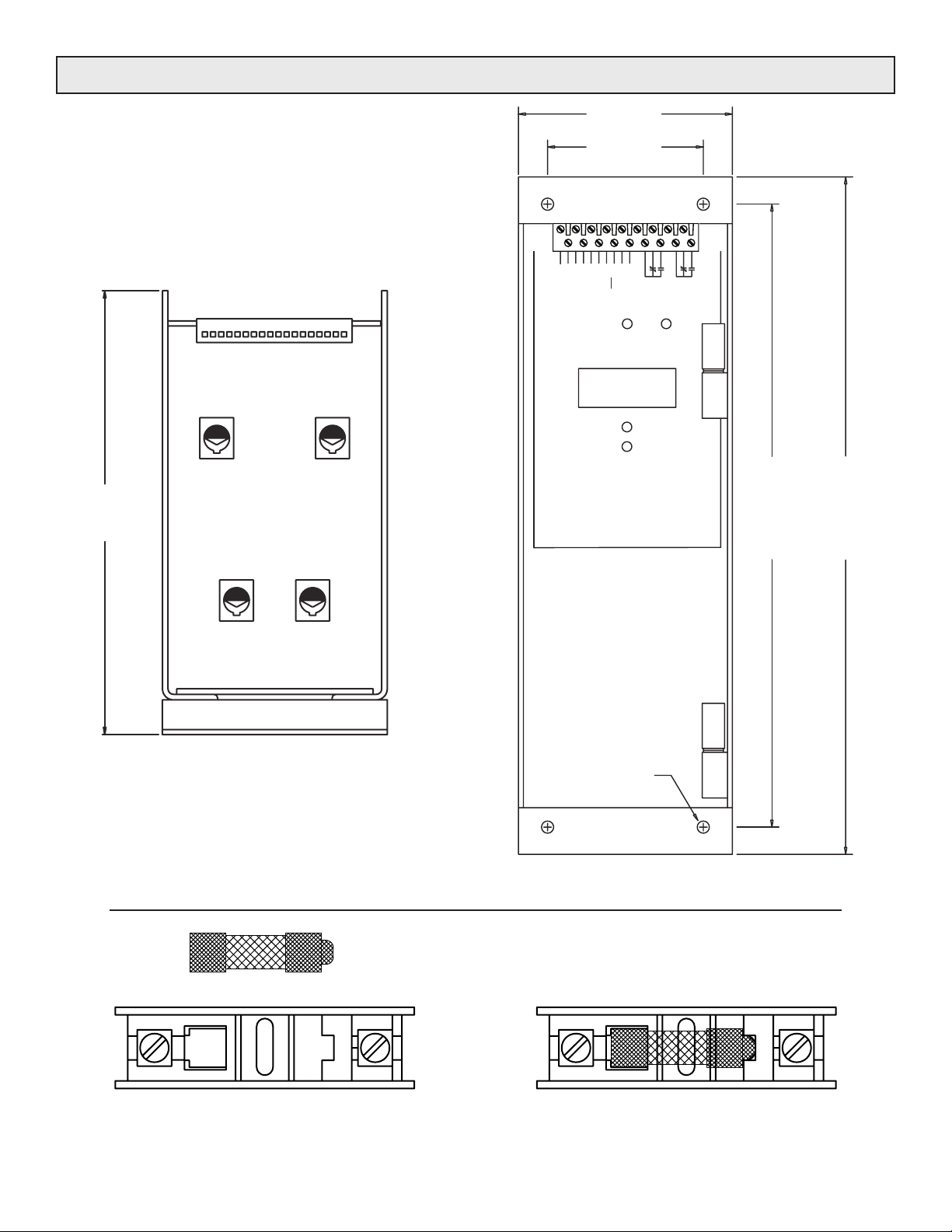
Figure 3. Installation drawing for 200, 250, 300,380 and 425 Amp units.
Figure 4.
ORIENTATION OF FUSE IN HOLDER
Fuse makes contact only when correctly installed.
MODEL 1029C 6 10/19/2007
Page 11
26.
1
INSTALLATION DRAWINGS (Continued)
13
0
18
W
. METER
FB. BK.
I. METER
V
IDLE (+)
COM(-) CCW
DANGER
HIGH VOLTAGE
COMMAND
1234567891011121314151617
W
CW
)
D
RESET
+5V
COMMON
TE
SHOR
CURRENT
AY
L
SCR
OVER
RE
RELAY
CURRENT
OVER
5
.
RUN/IDLE
RUN (+
SHORTED
SCR
INDICATOR
LOAD
INDICATOR
0
.
5
2
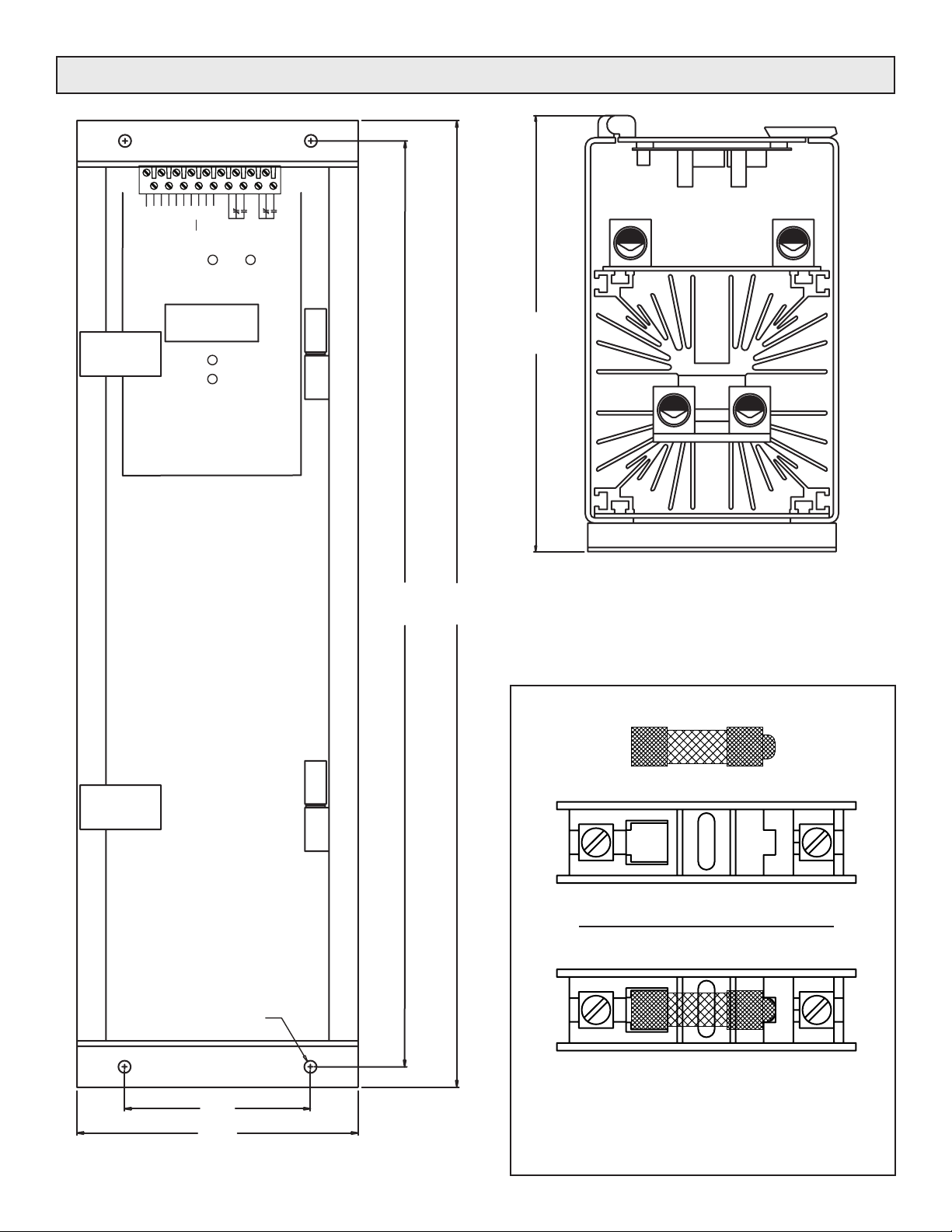
Figure 5. Installation drawing
for 500 to 750 Amp units.
0.332 Dia. (4)
5.00
Figure 6.
ORIENTATION OF FUSE IN HOLDER
Fuse makes contact only when correctly installed.
MODEL 1029C 7 10/19/2007
Page 12
COMMAND CONNECTIONS
OVER CURRENT TRIP
12
14
16
18
13
15
17
W
RESET SWITCH
10
11
8
9
CW
TO ALARM OR
POWER DISCONNECT
CIRCUIT
TO ALARM OR
POWER DISCONNECT
CIRCUIT
2
4
6
1
3
5
7
FB. BK.
I. METER
V. METER
IDLE (+) W
+5V
RUN (+)
COM(-) CCW
RESET
COMMON
RUN/IDLE
SHORTED
SCR
RELAY
OVER
CURRENT
RELAY
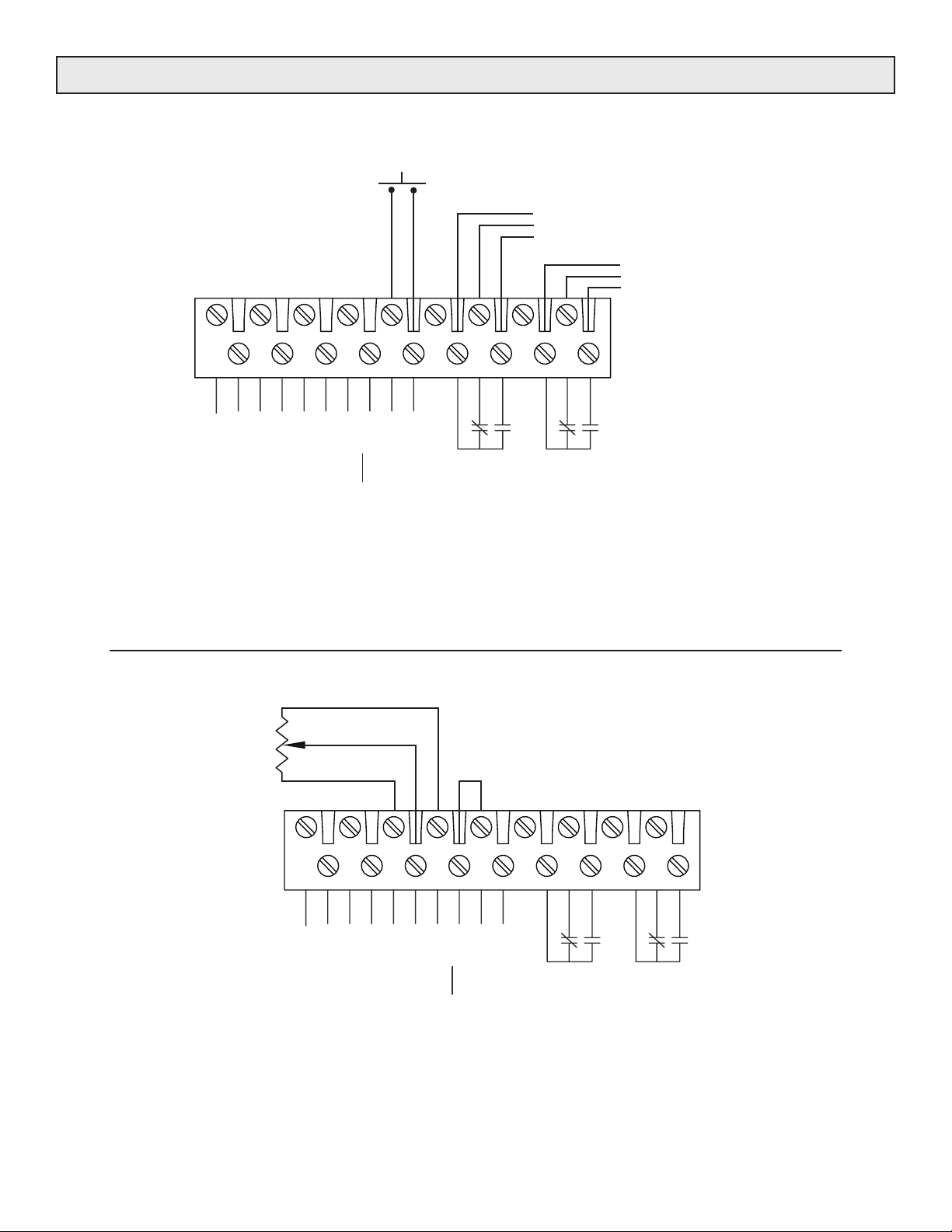
Figure 7. Voltage or current command connections.
OVER CURRENT RELAY CONTACTS CHANGE STATE WHEN AN OVERCURRENT CONDITION OCCURS
SHORTED SCR RELAY CONTACTS CHANGE STATE WHEN AN SCR FAILS IN THE SHORTED MODE
CW
I K
POT
CCW
18
WIPER
16
17
15
14
13
12
11
10
2
4
6
8
1
3
5
7
9
W
FB. BK.
I. METER
W
. METER
V
IDLE (+)
CW
+5V
COMMON
RUN/IDLE
RUN (+)
COM(-) CCW
RESET
TED
SCR
RELAY
SHOR
T
OVER
CURREN
RELAY
Figure 8. Single potentiometer applied to the run input connections.
(Terminals 10 & 11 must be connected to enable the run input.)
Effective 10/19/2007 the controller will be shipped with shorting jumper on pins 10 & 11.
MODEL 1029C 8 10/19/2007
Page 13
COMMAND CONNECTIONS (Continued)
POSITIVE(+)
RUN INPUT
(VOLTAGE OR CURRENT
COMMAND SIGNAL.)
2
4
1
3
5
AY
SCR
REL
OVER
CURRENT
RELAY
18
17
FB. BK.
14
16
15
I. METER
V. METER
IDLE (+) W
10
12
11
13
W
CW
+5V
RUN/IDLE
RUN (+)
COM(-) CCW
COMMON(-)
8
7
9
RESET
COMMON
6
TED
SHOR
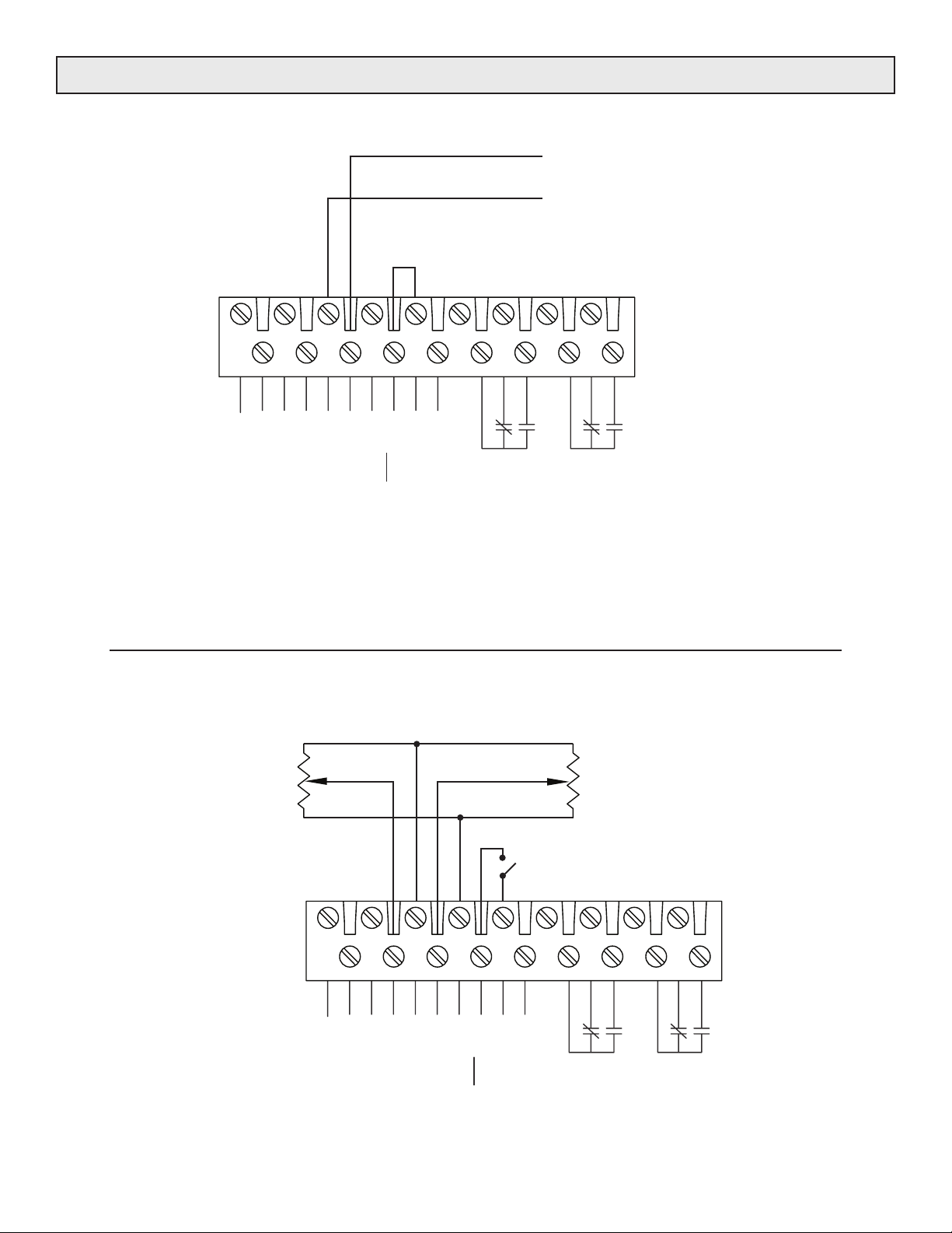
Figure 9. Single voltage or mA current applied to the run input connections.
(Terminals 10 & 11 must be connected to enable the run input.)
Effective 10/19/2007 the controller will be shipped with shorting jumper on pins 10 & 11.
IDLE POTENTIOMETER
CCW
I K
POT
CW
WIPER
18
17
FB. BK.
16
I. METER
V. METER
14
13
15
W
IDLE (+)
COM(-) CCW
RUN POTENTIOMETER
CCW
WIPER
CW
RUN/IDLE SWITCH
CLOSED ENABLES THE RUN INPUT
OPEN ENABLES THE IDLE INPUT
12
11
W
CW
)
+5V
RUN (+
10
RUN/IDLE
8
9
RESET
COMMON
7
I K
POT
6
SHORTED
5
SCR
RELAY
4
3
OVER
2
1
T
RELAY
CURREN
Figure 10. Run and Idle potentiometer connections.
MODEL 1029C 9 10/19/2007
Page 14
COMMAND CONNECTIONS (Continued)
POSITIVE(+)
COMMON(-)
RESET
COMMON
SHORTED
RUN INPUT
(VOLTAGE OR CURRENT
COMMAND SIGNAL.)
246810121416
SCR
OVER
RELAY
CURRENT
(VOLTAGE OR CURRENT*
IDLE INPUT
COMMAND SIGNAL.)
POSITIVE(+)
COMMON(-)
18
FB. BK.
I. METER
V. METER
IDLE (+) W
W
CW
+5V
RUN/IDLE
RUN (+)
COM(-) CCW
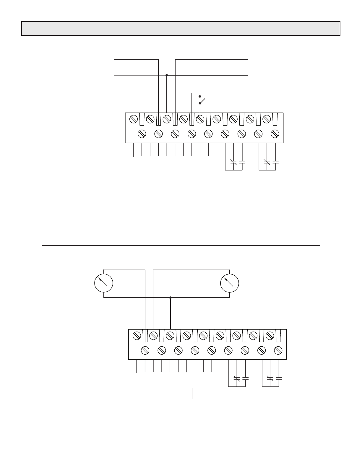
Figure 11. Run and Idle voltage or current connections.
* If it is desired to use a current command in both the Run and Idle command input,
the signals must either be common sourcing, or they must be isolated from one another.
Contact factory for details.
1357911131517
AY
REL
CURRENT METERING
OUTPUT
+
-
18
17
FB. BK.
16
. METER
I. METER
V
14
13
15
W
IDLE (+)
COM(-) CCW
12
11
W
CW
+5V
RUN/IDLE
RUN (+)
VOLTAGE METERING
OUTPUT
+
-
COMMON
4
6
10
8
7
9
T
RESE
COMMON
5
TED
SCR
SHOR
AY
REL
3
OVER
2
1
RELAY
CURRENT
Figure 12. Output metering connections.
MODEL 1029C 10 10/19/2007
Page 15
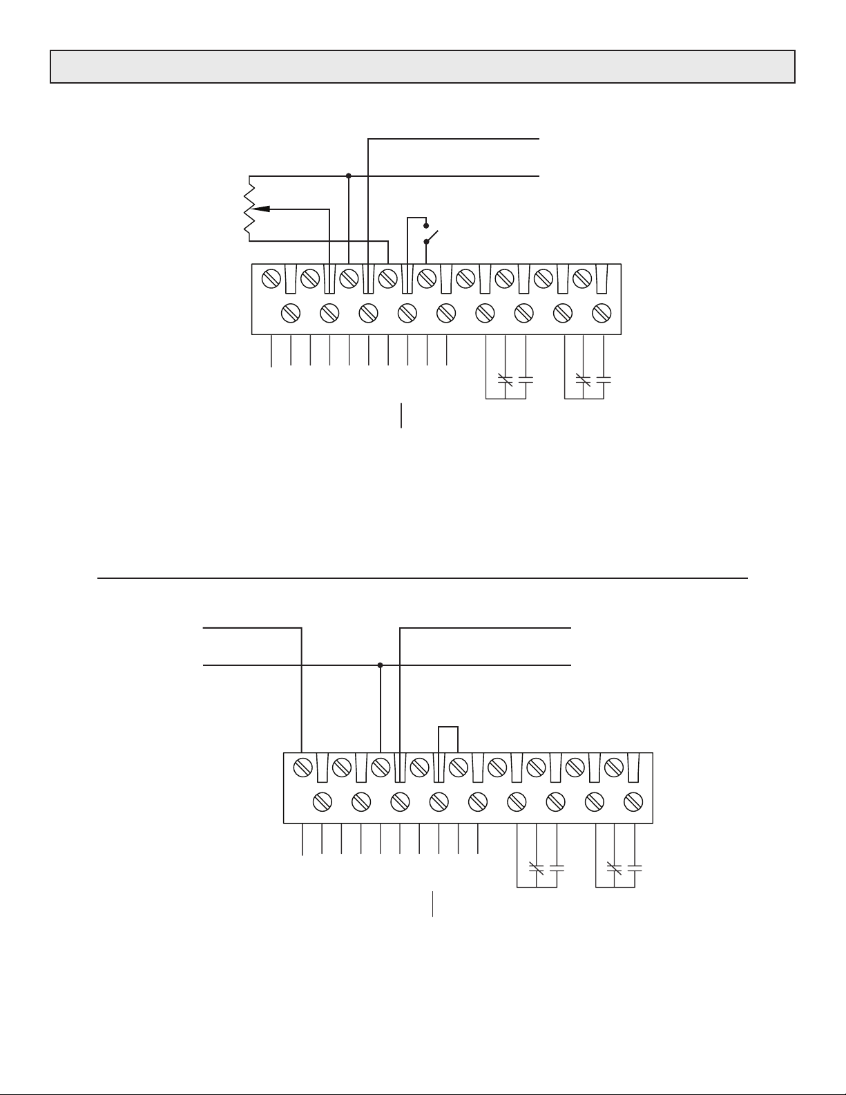
COMMAND CONNECTIONS (Continued)
IDLE POTENTIOMETER
CCW
I K
POT
CW
18
WIPER
16
17
15
14
13
W
12
11
CW
POSITIVE(+)
RUN INPUT
(VOLTAGE OR CURRENT
COMMON(-)
RUN/IDLE SWITCH
CLOSED ENABLES THE RUN INPUT
OPEN ENABLES THE IDLE INPUT
8
10
7
9
COMMAND SIGNAL.)
4
6
5
3
2
1
EXTERNAL
FEEDBACK
SIGNAL
FB. BK.
I. METER
V. METER
IDLE (+) W
+5V
RUN (+)
COM(-) CCW
RESET
COMMON
RUN/IDLE
SHORTED
AY
SCR
REL
OVER
CURRENT
RELAY
Figure 13. Combination command-signal/potentiomter input connections.
(This is the most common use of a run/idle control.)
POSITIVE(+)
COMMON(-)
18
16
14
12
10
POSITIVE(+)
COMMON(-)
6
8
RUN INPUT
(VOLTAGE OR CURRENT
COMMAND SIGNAL.)
2
4
17
FB. BK.
I. METER
V. METER
13
15
IDLE (+) W
COM(-) CCW
11
W
CW
+5V
RUN (+)
9
T
RESE
COMMON
RUN/IDLE
SHORTED
SCR
RELAY
OVER
URRENT
C
AY
REL
1
3
5
7
Figure 14. External feedback with signal applied to run input connections.
0 - 5 Vdc or 0 - 50uA external feedback.
(Terminals 10 & 11 must be connected to enable the run input.)
Effective 10/19/2007 the controller will be shipped with shorting jumper on pins 10 & 11.
MODEL 1029C 11 10/19/2007
Page 16
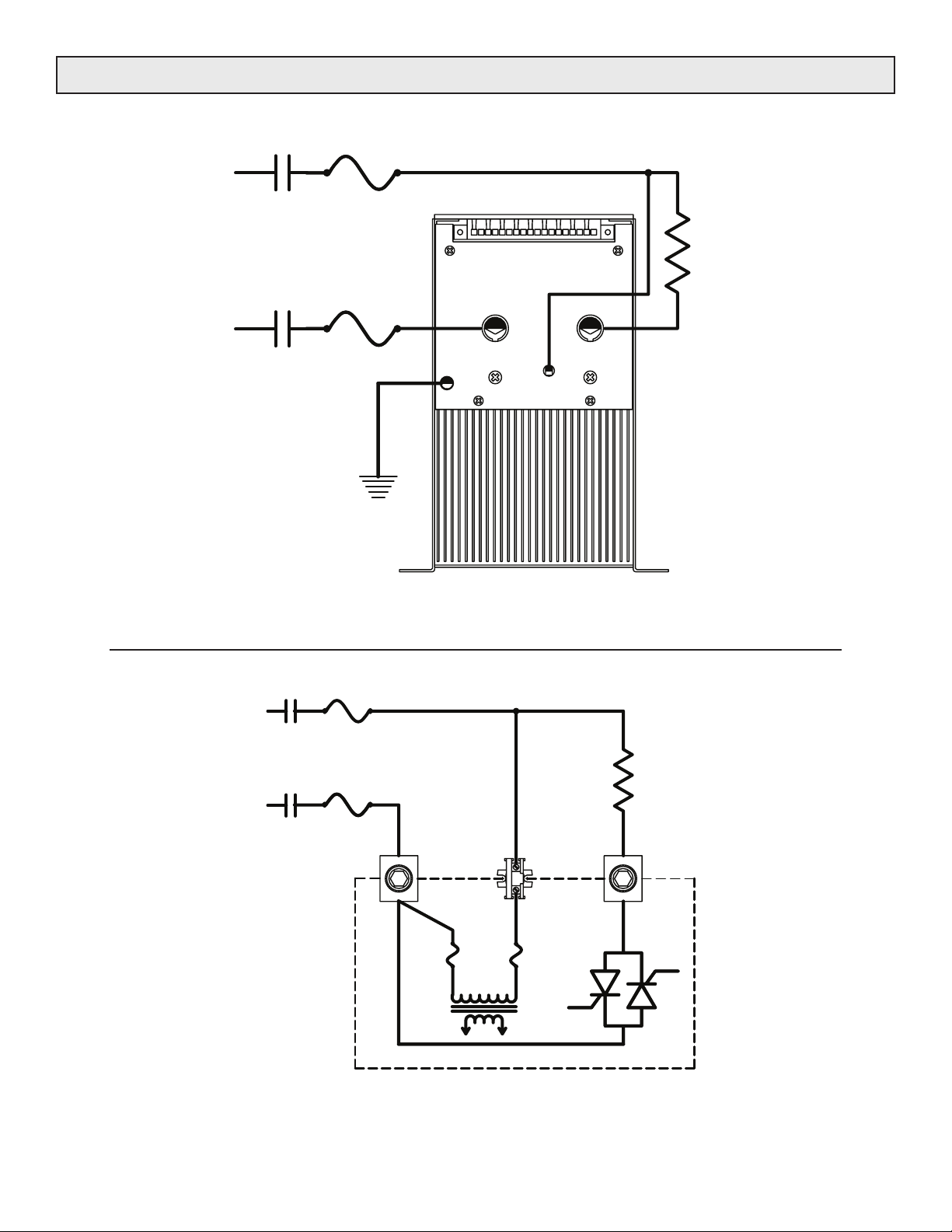
POWER CONNECTIONS
LINE 2
VOLTAGE
SUPPLY
LOAD
LINE 1
LINE 2
VOLTAGE
SUPPLY
LINE 1
GND
Figure 15. Power Connections.
1
LOAD 1
LINE 2
1
LOAD
LINE 1
MODEL 1029C 12 10/19/2007
LINE
1029C CONTROLLER
Figure 16. Power Path.
LINE 2
LOAD
Page 17

FEEDBACK SELECTION
START-UP
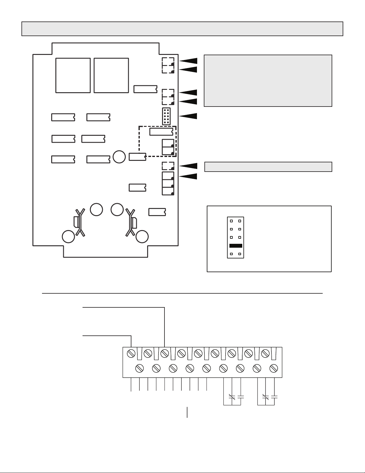
Connector P2 on the circuit board allows the selection of
feedback type. (See Figure 18).
True RMS is the default voltage feedback mode. Average
voltage feedback mode may be requested when ordering
the controller.
Voltage feedback may be selected by placing the jumper
across pins P2-4 and P2-7. (VFB)
Current feedback may be selected by placing the jumper
across P2-3 and P2-8. (IFB)
Power feedback, if factory installed, may be selected by
placing the jumper across P2-5 and P2-6. (PFB)
External feedback may be connected between terminals
P1-14 (Common) and P1-18 (FD. BK.) on the command
connector (See Figure 19).
A 0-5Vdc signal may be used for external feedback when
the jumper is placed across pins P2-2 and P2-9 (EXT).
A 0-100uA signal may be used for external feedback when
the jumper is placed across pins P2-1 and P2-10 (SJ).
Average voltage and True RMS voltage are of the
feedforward technique.
Determine that the selected transformer tap corresponds to
the line voltage.
If the customer wishes to determine that the controller and
the command signals are wired and operating correctly
before applying power to the load, the following procedure
may be followed.
A load capable of drawing at least one amp must be
connected for the controller to operate properly.
1. Move the feedback jumper to pins P2-4 & P2-7 to select
Voltage FB. (See Figure 18.)
2. Determine that terminals P1-10 & P1-11 are electrically
connected. Apply a command signal to the run
command signal input.
3. Set the command signal to zero before applying system
power. The load voltage should start at zero and
increase as the command signal is increased, reaching
optimum line output when command signal is maximum.
4. Remove system power from controller. Remove
electrical connection from between P1-10 & P1-11.
Apply a command signal to the idle command signal
input and repeat step 3.
The load voltage and current may be measured with any
meter. However, for accurate RMS voltage
measurements use a True RMS responding meter. Use
an average responding meter for average voltage
measurements.
5. When start-up tests have been completed, move the
feedback jumper to select the desired operating
feedback.
The controller was calibrated at the factory.
If adjustments appear necessary, see the zero and span
adjustment instructions on page 14.
Care is urged whenever working near high voltages, and it
is recommended that installation and service be done by a
licensed electrician or experienced technician.
MODEL 1029C 13 10/19/2007
Page 18
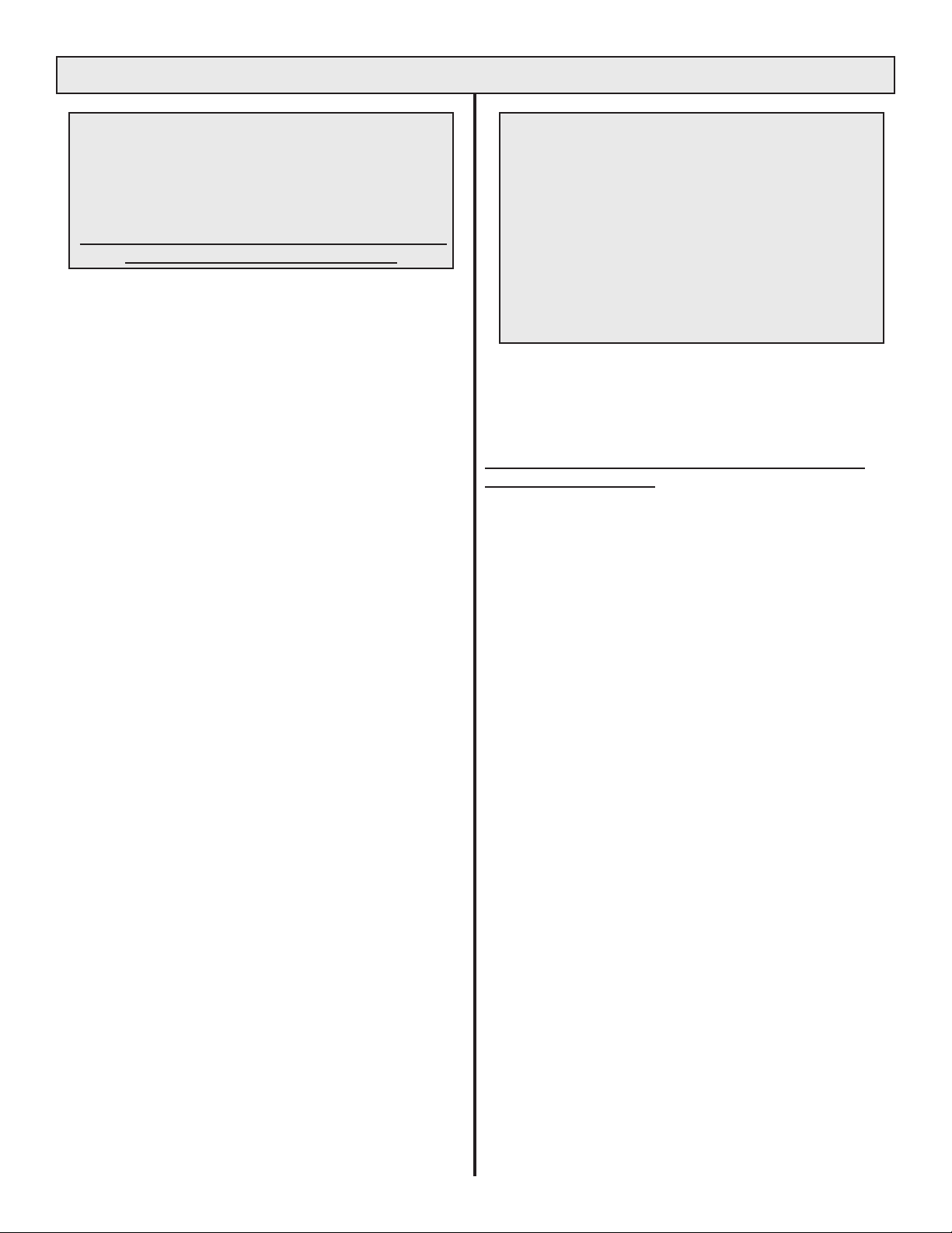
ADJUSTMENTS
The I Span and V Span pots (and Power
Span and Power Zero pots, when factory
installed), are sealed at the factory. They are
identified with an X in Figure 17. Under no
circumstances should adjustment of these
four pots be attempted.
The setting of each of these potentiometers is critical
to the proper operation of the controller.
The potentiometers labeled Run Span, Run Zero, Idle
Span & Idle Zero have been calibrated at the factory and
readjustment should not be necessary.
The zero pots are adjusted to provide zero output when
the command signal is at minimum. The span pots are
adjusted to provide full output when the command signal is
at maximum.
If it is determined that the adjustment should be changed,
the following procedure should be followed:
It is assumed that the load is resistive and can draw at least
one or more amps.
Run Zero and Run Span:
Determine that pin P1-11 (Run/Idle) is electrically
connected to pin P1-10 (Common). Make sure that the
command signal is connected between the Run input P1-13
(Run/Wiper) and P1-14 (Common).
It is important that meters capable of
accurately measuring the output of the
controller be used.
True RMS meters should be used for accurate
measurements of True RMS Voltage, Current or
Power (RMS Volts times RMS current into a resistive
load).
Average responding meters should be used for
measurements of;
Average AC Voltage or DC voltage.
Current Limit:
(The current limit pot is factory set at 105% of rated current
unless specified differently by the (IL) term in the model
Number.)
Proper calibration of the current limit feature requires a
True RMS current meter.
If it becomes desirable to reset the current limit level:
1. Rotate the current limit pot fully counter- clockwise.
(This is a multiple turn pot.)
2. Carefully increase the command signal to maximum.
3. Slowly rotate the current limit pot in a clockwise
direction until the desired load current is reached.
1. Set the command signal to minimum and adjust the Run
zero potentiometer until the output is zero.
2. Set the command signal to maximum and adjust the
Run span potentiometer until the output is at the desired
maximum value.
3. The span and zero adjustments may interact, making it
necessary to repeat steps 1 and 2.
Idle Zero and Idle Span:
Remove the electrical connection from between P1-11
(Run/Idle) and P1-10 (Common). Make sure that the
command signal is connected between the Idle input P1-15
(Idle/Wiper) and P1-14 (Common). Repeat steps 1,2 and 3
(above) on the idle zero and span potentiometers.
If it is suspected that the current limit adjustment is causing
the output of the controller to be lower than desired, rotate
the current limit pot clockwise. If the load voltage increases,
the current limit adjustment has been controlling the output.
Follow the steps above to set current limit to the desired
level.
OVER CURRENT TRIP:
This potentiometer has been factory set at 150% of rated
frame current. For optimum protection, the customer may
wish to reduce the level at which Over Current Trip occurs.
1. Adjust command signal to maximum.
2. Slowly rotate the Over Current Trip pot counterclockwise
until the Over current Trip occurs.
3. Rotate the Over Current Trip pot about 1/2 turn
clockwise.
4. Reset the Over Current Trip circuit.
MODEL 1029C 14 10/19/2007
Page 19
ADJUSTMENTS (Continued)
Run Span Pot.
Run Zero Pot.
Idle Span Pot.
Idle Zero Pot.
THESE FOUR POTS, AND
THE CURRENT LIMIT POT
ARE MOUNTED ON THE
BACK SIDE OF THE BOARD
TO SHOW THROUGH LID
Installed
for power
feedback
only
X
X
X
X
Figure 17. 1029C circuit board showing adjustment locations.
P2 FeedbackSelector. See Figure 18
DO NOT CHANGE ADJUSTMENTS
ON POTS MARKED WITH AN ‘X’
Current Limit Pot. (shows through lid.)
Over Current Trip
DO NOT CHANGE ADJUSTMENTS
ON POTS MARKED WITH AN ‘X’
FEEDBACK SELECTION
SUMMING JUNCTION
EXTERNAL F.B.
CURRENT F.B.
VOLTAGE F.B
POWER F.B.
Figure 18. P2 Details
COMMON
EXTERNAL FEEDBACK
INPUT CONNECTIONS
0-100mA or 0-5 V
18
17
FB. BK.
14
16
15
I. METER
V. METER
IDLE (+) W
10
12
11
13
W
CW
+5V
RUN/IDLE
RUN (+)
COM(-) CCW
8
7
9
RESET
COMMON
SHORTED
5
SCR
RELAY
3
OVER
1
RELAY
CURRENT
2
4
6
Figure 19. External feedback connections.
MODEL 1029C 15 10/19/2007
Page 20
TROUBLESHOOTING
CAUTION: HIGH VOLTAGES ARE PRESENT ON THIS
CONTROLLER AND ON PORTIONS OF THE PRINTED
CIRCUIT BOARD. USE EXTREME CARE TO AVOID
ELECTRICAL SHOCK.
Notes: The LED's provide a convenient method of
determining the general location of controller problems.
The LOAD LED indicates that 10% or more of rated load
current is present. The intensity of the LOAD LED should
increase as the command signal is increased. The
COMMAND LED indicates the presence of gate drive. The
O.C.T. LED is a fault indicator to warn that an Over Current
condition has occurred, the O.C.T. relay is energized and
the SCR's are prevented from turning on. The SHORTED
SCR LED is a fault indicator to warn that one or more
SCR's may be shorted.
NO LOAD VOLTAGE:
• Determine that the Command LED lights when the
command signal is increased from zero.
If the command LED will not light.
• Determine that the following conditions exist: (Measure
voltages at screw terminals to ensure good electrical
connections.)
• Determine if OVER CURRENT TRIP LED is ON.
• Voltage between COM (Pin 14) and +5CW (Pin 12) must
be 5 Volts ±1. If not; Circuit is not powered or command
connections are shorting out supply.
• Determine that line voltage exists between Line 1 and
Line 2 terminals.
• Determine that fuses on controller are OK.
• Remove connections to CW (terminal 12).
Voltage or potentiometer inputs.
• Determine that voltage from COM (pin 14) to IDLE (W)
or RUN (W) changes from 0 to 5 Vdc as command is
changed from zero to 100%.
LOAD VOLTAGE WILL NOT GO TO ZERO:
If RMS value of the load voltage is greater than 10
percent of the supply voltage.
• Determine SHORTED SCR LED status while varying the
command signal.
• With power removed and the load disconnected from
terminal Load 1 the resistance between terminals Line 1
and Load 1 should be greater than 100K ohms.
• If the resistance between Line 1 and Load 1 is less than
100K ohms the SCR module has failed.
• If the shorted SCR led is ON & the resistance between
Load 1 and Line 1 is greater than 1000 ohms, the failure
is likely associated with the circuit board. Determine by
removing the circuit board and applying power.
• Determine that the supply to line 2 and the load are
connected to the same supply.
If the RMS value of the load voltage is less than 10
percent of the supply voltage.
• Determine that the command signal is correct. Adjust
the zero and span potentiometers to achieve the desired
output. (Note: The Zero and span potentiometers are
factory set. Adjustment should be made with caution.
FULL VOLTAGE CANNOT BE OBTAINED:
• Determine that the control signal is at maximum.
• Determine that the controller is not in current limit
Decrease the current limit by rotating the current limit
potentiometer counterclocklwise, the controller is in
current limit if the load voltage decreases.
• If the problem occurs on initial start up, determine that
line 2 and the load are connected to the same supply.
MANUFACTURED BY
4/20 mA inputs:
• Determine that voltage from COM (pin 14) to IDLE (W)
or RUN (W) changes from 1.2 to 6 Vdc as command is
changed from 4 to 20 mA.
• Determine that there is no connection between terminals
9 & 10.
If the command LED can be made to light:
• Determine that the load fuses are OK and that the load
has continuity. Load continuity (including load fuses can
be confirmed by determining that the supply voltage
exists between Line 1 and Load 1 terminals when the
command signal is zero.
MODEL 1029C 16 10/19/2007
7870 PARK DRIVE, CHANHASSEN, MN 55317
TEL: 952-474-6200 FAX: 952-474-6070
TOLL FREE: 800-765-2799
www.ccipower.com U.S.A
Page 21
REPLACEMENT PARTS
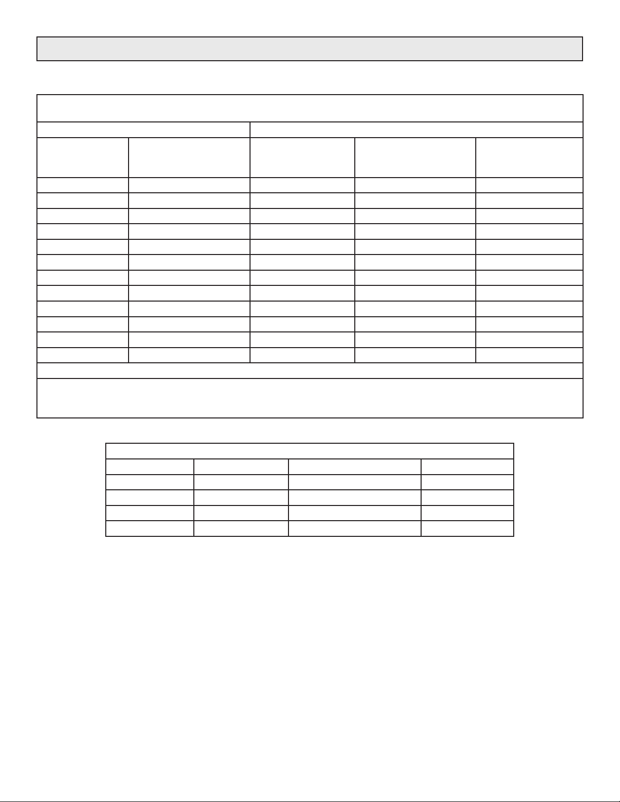
SCHEMATIC DWG: CCI No. D1000954A
ITS RECOMMENDED THAT THE CONTROLLER AND LOAD
BE PROTECTED BY 600 VOLT, CLASS ‘T’ FUSES:
TO ORDER A SPARE SCR MODULE: TO ORDER CLASS ‘T’ FUSES
CONTROLLER
CURRENT
RAING Amps (A)
50 SCR/TT91-16 50 60 42110-0460-360
80 SCR/TT91-16 80 100 42110-0460-410
120 SCR/TT105-16 120 150 42110-0460-415
160 SCR/TT132-16 160 200 42110-0460-420
200 SCR/T240-14* 200 250 42110-0460-425
250 SCR/T340-14* 250 300 42110-0460-430
300 SCR/T490-14* 300 350 42110-0460-435
380 SCR/T600-14* 380 450 42110-0460-445
425 SCR/T760-14* 425 500 42110-0460-450
500 SCR/T600-14* 500 600 42110-0460-460
600 SCR/T760-14* 600 700 42110-0460-470
750 SCR/Z1400-14* 750 800 42110-0460-480
CONTACT FACTORY FOR INFORMATION ABOUT 1000 OR 2000 AMP FRAME
* Because of critical assembly requirements, it is recommended that replacement of SCRs on 200 Amp and larger
controllers be done at the factory. If you desire to try it yourself, request a copy of our technical bulletin concerning
replacement of SCR's on the 3629 controller.
CONTROL
CONCEPTS
PART No.
CONTROLLER
CURRENT
RATING Amps (A)
FUSE SIZE
Amps (A)
CONTROL
CONCEPTS
PART No.
REPLACEMENT CONTROL TRANSFORMER FUSES
Frame Size Location Fuse Type CCI Part No.
50 & 80 Amps F1 & F2 1/4 Amp Class CC TYPE R 42130-0460-2025
120 - 425 Amps F1 & F2 1/2 Amp Class CC TYPE R 42130-0460-205
500 - 750 Amps F1 1 Amp Class CC TYPE R 42130-0460-210
500 - 750 Amps F2 1/2 Amp Class CC TYPE R 42130-0460-205
MODEL 1029C 17 10/19/2007
Page 22

MODEL NUMBER IDENTIFICATION
1029C
The basic model number.
[X] The type of feedback
A - Specifies average voltage feedback. With average voltage feedback,
the controller varies the conduction angle (or ON time) of the SCRs
such that the average voltage applied to the load is proportional to
the command signal.
E - Specifies external feedback. The external feedback being
proportional to some parameter such as speed, current, etc. that is
ultimately being controlled by the action of the controller.
I - Specifies RMS current feedback. The load current is linearly controlled
with respect to the command signal.
P(XXXAMPS) - The letter P specifies power feedback and therefore the
load power is linearly controlled with respect to the command signal.
XXX equals amp level for control of power. MAX LOAD POWER =
(VOLTS)V x P(AMPS)
V - Specifies RMS voltage feedback. With RMS voltage feedback, the
controller varies the conduction angle (or ON time) of the SCRs
such that the RMS voltage applied to the load is proportional to the
command signal.
1029C-[X]-[XXX]V-[XXX]A-IL[XXX]-R[XXX]-I[XXX]
[XXX]V Operating Voltage
120, 208, 240, 277, 380, 415, 480 or 575 Vac
Note: unless otherwise specified, the controller is shipped with a
transformer that has primary voltage taps at:
240, 480 or 575 volts, 50/60 Hz.
[XXX]A Operating Current
50, 80, 120, 160, 200, 250, 300, 380, 425, 500, 600 or 750
(consult factory for 1000 & 2000 Amps)
IL[XXX] Current Limiting
Up to 105% of controller rating.
R[XXX] Run Command Signal
0/5Vdc, 4/20mA or Potentiometer
I[XXX] Idle Command Signal
0/5Vdc, 4/20mA or Potentiometer
Example:
1029C-A-480V-80A-IL75-R0/5V-IPOT
Will order a 1029C controller with average voltage feedback, rated @ 480 Volts, 80 Amps, current limit set at 75 Amps,
run command signal of 0 to 5Vdc and a potentiometer on the idle command input.
If a "SC(VVV) term is included, it implies special calibration, meaning that the controller has been calibrated for a
maximum output of (VVV) voltage rather than the rated (line) voltage. Contact factory for information.
MODEL 1029C 18 10/19/2007
Page 23
THEORY OF OPERATION
THE SCR
The heart of the Control Concepts, Inc. power controller is
the SCR (silicon controlled rectifier, sometimes referred to
as a thyristor).
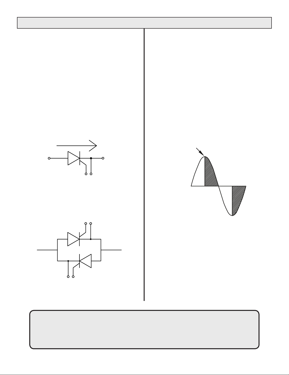
The SCR has two states, ON and OFF, and allows current
to flow in only one direction when turned on. SCRs can
remain in the off state even though the applied potential
may be up to 1600 volts.
In the on state, they can pass several thousand amperes.
When a small signal is applied between the gate and
cathode terminals (Figure 20), the SCR will turn on within
10-100 microseconds.
Once turned on, it will remain on until the current through it
is reduced below a very low value, referred to as the
holding current.
CURRENT FLOW
ANODE
CATHODE
PHASE-ANGLE OPERATION
In phase-angle control, each SCR of the back-to-back pair
is turned on for a variable portion of the half-cycle that it
conducts. (Figure 22).
Power is regulated by advancing or delaying the point at
which the SCR is turned ON within each half cycle. Light
dimmers are an example of phase-angle control.
Phase-angle control provides a very fine resolution of
power and is used to control fast responding loads such as
tungsten-filament lamps or loads in which the resistance
changes as a function of temperature.
Phase-angle control is required if the load is transformercoupled, capacitive, inductive or a variable resistance load
requiring current limiting.
Point at which
SCR begins to
conduct
GATE
Figure 20. SCR symbol
Because the SCR allows current to flow in only one
direction, two SCR’s are connected in an inverse parallel
(back to back) configuration to control AC current.
Figure 21. “AC Switch”
WARNING: the Control Concepts, Inc, model 1029C power controller uses power thyristors to switch
voltage to the connected load. Line voltage must be assumed at the output terminals at all times, even
when the control signal has been removed and the load voltage appears to be off.
It has been mandated by the National Electrical Code and the Occupational Safety and Health Act of 1970
that a physical disconnect be opened ahead of all remotely actuated controls before
performing any maintenance work on the controller or its connected load.
Figure 22. SCR “ON” time, shown by shaded area, is
varied to apply the desired load voltage
MODEL 1029C 19 10/19/2007
 Loading...