

Page 1
Model 4555 User’s Manual
Publication #: 107679-001 Rev. A
July 2005
Another quality product from:
7128 Shady Oak Road, Eden Prairie, MN 55344
Phone: (952) 949-9009 Fax: (952) 949-9559
E-mail: [email protected]
www.researchinc.com
Page 2

Dear Valued Customer:
Thank you for purchasing a Model 4555 PanelIR
type and are confident you will think so too.
For technical assistance, training, replacement parts and assemblies, or any other problems or questions, contract
our Field Service specialists. They will do everything they can to help you or will put you in touch with someone
who can.
This instruction manual has been carefully prepared to make sure you get out of your system all of the capabilities
we designed and built into it. To tell us how we could make the system, our support of it, or this manual even
more useful, we invite you to call our product manager with your suggestions and recommendations.
Additional copies of this manual are available at reasonable cost from our Customer Service Department. Once
again, let us welcome you to the growing family of Research, Inc. customers. We look forward to working with
you in the future.
Requirement
Additional information regarding application Your local sales representative.
of the Model 4555 system or other Research Inc.
products.
Ordering additional Research Inc. products or Manuals. Your local sales representative or
Technical assistance and training. Research Inc. Factory Service
(952) 949-9009
Sincerely,
Terry Nigon
President
Research Inc.
Appropriate Contact
®
Infrared Pyropanel. We believe it is the finest system of its
Research, Inc. Customer Service (952) 940-9009
Page 3

Model 4555 PanelIRTM User Manual Contents
Section Page
SAFETY
1
PRODUCT DESCRIPTION 2
Dimensions 7
INSTALLATION
Mechanical Installation 11
Electrical Installation
Single Phase Wiring
Three Phase Wiring 15
Lamp Installation 19
Thermostat Wiring 20
Pressure Switch Wiring 20
Blower Wiring 21
12
14
OPERATING INSTRUCTIONS 22
MAINTENANCE INSTRUCTIONS 23
Appendix A Multiple Heater Wiring 24
Page 4

Model 4555 PanelIRTM User Manual Safety
General
Electrical
Safety
Heater
Safety
Infrared
Radiation
Safety
The Model 4555 Heater is designed for safe operation. Nevertheless, installation,
maintenance, and operation of the heater can be dangerous for a careless operator or
maintenance person. For your safety and the safety of others, read the instructions in this
manual and follow these warnings to help prevent accident or injury.
Due to high voltages present in typical Model 4555 installations there is danger of
electrical shock when installing, operation, or servicing the heater. Exercise extreme
caution when handling or working with these high voltages.
All applicable local and national electrical codes should be followed to ensure proper
installation and operation of the Model 4555. A safe electrical ground must also be
provided and properly installed on the heater before attempting to operate the unit.
WARNING!
Power lines and any other affiliated heater circuitry (i.e., blowers, thermostat, etc.)
must be disconnected prior to any servicing issue including lamp installation and
change out.
The Model 4555 heater should never be operated with the end covers of the heater
removed.
The presence of open load-to-ground must be verified after lamp installation into the
Model 4555 and before system power is applied.
Certain areas of the Model 4555 heater may exceed 500° F (260° C) while the heater is in
operation. Exercise extreme care when working in close proximity to an operating heater.
WARNING!
NEVER place any part of the body under or near any part of the heater while power is
applied.
Always allow the heater to cool sufficiently (at least 5 minutes with the blower operating,
longer if the blower is not operating) before servicing any part of the heater, including
lamps or adjacent parts.
CAUTION! Continuous exposure to high-intensity infrared radiation at close
proximity could be harmful to eyes or skin. Although infrared lamps emit negligible ultra
violet electromagnetic radiation, harmful burns can still result if an operator is in close
contact with lamps being operated at high intensity.
Because of the brilliant light emitted by infrared lamps at full intensity, it is recommended
that eyes be shielded from the glare if observing the lamps for an extended period of time.
Use suitable shaded lenses or dark glasses.
Research Inc.
1
Page 5
Model 4555 PanelIRTM User Manual Product Description
PRODUCT DESCRIPTION
Model 4555
Infrared Heat. Applications
Instantaneous Results.
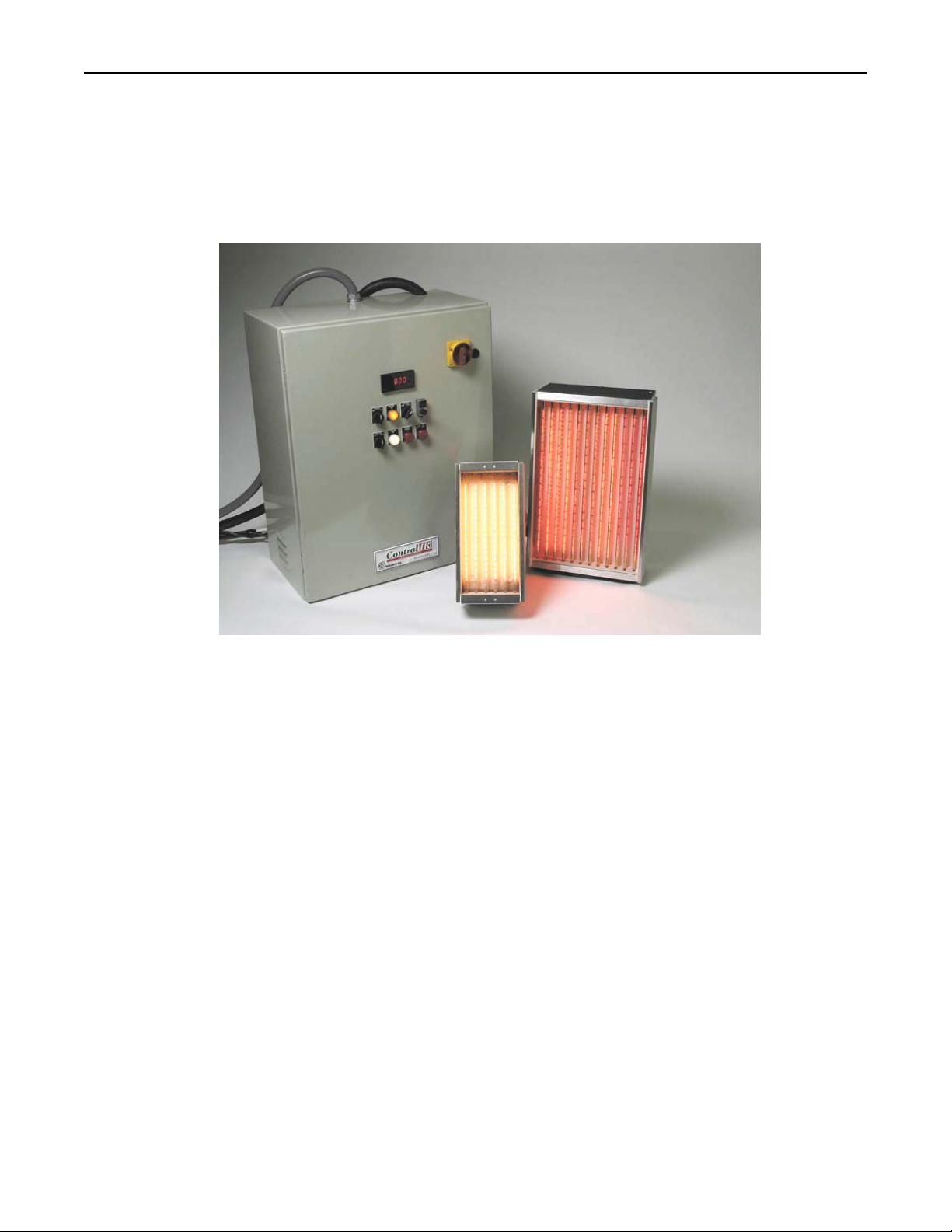
The Model 4555 High Density Infrared Panel heater is a modular,
panel-type heating unit that combines radiant and convection
heating techniques. A forced air flow system turns waste heat into
usable energy and allows the heater to operate efficiently at very
high power levels. This heater is available with either
medium-wavelength or short wavelength lamps.
You also have the choice of a ceramic reflector or an
aluminum reflector.
Research, Inc.
2
• Activating Thermo Transfer
• Ceramic Processing
• Cure and Melt Powders
• Curing
• Dry and Cure Paint
• Dry Adhesive
• Drying Coatings
• Laminating Composites
• Pre-Cure
• Preheating
• Resin Curing
• Soldering/ Desoldering
• Structural Tests
• Thermoforming
• Thick Film Drying
• Vulcanizing
• Weld Stress Relief
Page 6
Model 4555 PanelIRTM User Manual Product Description
Product Description-PanelIR 4555
Heater Construction
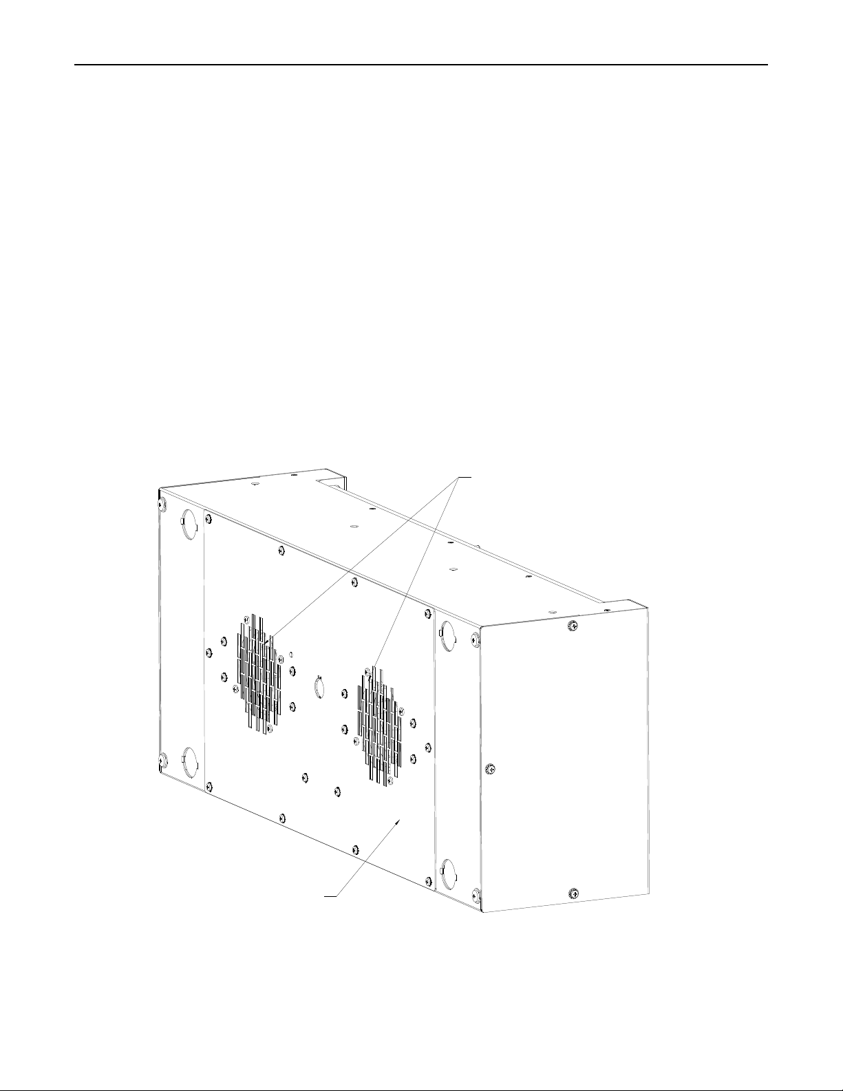
Metal Housing
The Model 4555 PanelIR uses rugged stainless steel and aluminum housing to contain the lamps, blowers and reflector.
Reflector
A polished aluminum or ceramic reflector is installed in the housing in back of the lamps to direct the heat toward the product. The
choice of ceramic or polished aluminum is based on the application.
Polished Aluminum Reflector
Polished Aluminum Reflectors are the most commonly used. They have a lower thermal mass than ceramic and as a result,
they allow the heater to respond quicker to changes in the lamp temperature.
Ceramic Reflector
A ceramic reflector is generally used for applications where smoke or dirt are released as a part of the process.
These contaminates will burn off of the ceramic reflector during operation so the reflector will not require cleaning.
The ceramic reflector is heavier than a polished aluminum reflector and has more thermal mass to it to take as
much as 10 minuets to heat up to operating temperature and to cool down when the lamps are shut off.
Forced Air Blowers
Blowers are installed in the housing behind the reflector. The blowers pressurize the chamber behind reflector and force air through the
holes in the reflector to enhance the heating capability of the panel and to cool the end seals on the lamps.
FORCED AIR BLOWERS
METAL HOUSING
Research, Inc.
3
Page 7
Model 4555 PanelIRTM User Manual Product Description
Product Description-PanelIR 4555 cont.
Heater Construction cont.
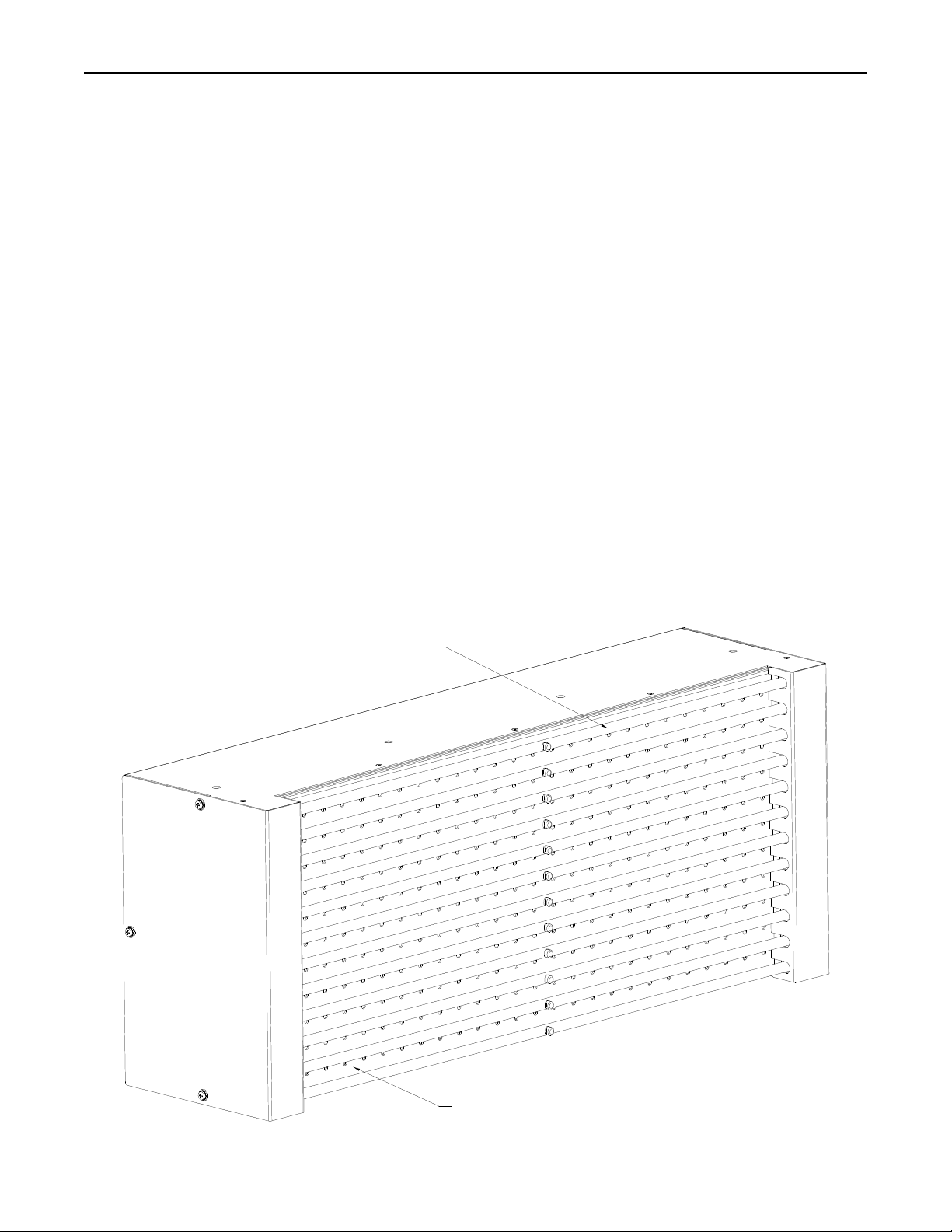
Infrared Lamps
Short Wavelength Lamp
These lamps are generally used in applications where a product is to be heated or cured. These lamps may be operated in
horizontal or vertical orientations. Typical short wavelength applications include:
Heat treating metals
Annealing metals
Localized softening plastics for bending or forming
Curing silicone and other rubber extrusions
*Limitations
Absorption of short wavelength is affected by product color. Black and dark colors absorb well. Heating lighter colors may be
more readily achieved with medium wavelength lamps.
Medium Wavelength Lamps
These lamps are generally used in applications where a surface needs to be dried. They may only be operated in a
horizontal orientation.
High speed drying of water or solvent based ink
Removing water after coil coating
Heating substances such as Teflon that do not absorb short wavelength
Heating lighter colored surfaces
*Limitations
Medium wavelength does not penetrate as deeply into metals, plastics, or rubber as short wavelength. They may only be
operated in a horizontal orientation.
LAMPS
CERAMIC OR ALUMINUM REFLECTOR
Research, Inc.
4
Page 8

Model 4555 PanelIRTM User Manual Product Description
Product Description-PanelIR 4555 cont.
Controls
The model 4555 PanelIR heater is designed to be powered by one of the standard Research Inc. control panels. The model of the
control panel required depends on (1) the voltage and amperage required to power the panel, (2) the electrical service in the facility,
and (3) the type of temperature control required for the process.
The 900 series control panels are for single phase power and the 925 series panels are for three phase power. Both series can be
specified with circuit breakers from 20 amps to 80 amps and with manual or set point control.
Terminal blocks inside the panel allow co nvenient termination for incoming power, all lamps and the forced air blo wer. A step down
transformer is included in the 480 volt panel to power the 220 volt blowers.
Power Controller Chart for Model 4555 PanelIR
This chart shows the control panels that are available for all sizes of the Model 4555 PanelIR heater.
Heater Module
240 Volt 1 Phase
900-240-20 Model 4555-05-06
900-240-40 Model 4555-05-12
900-240-40 Model 4555-10-06
900-240-40 Model 4555-10-09
900-240-60 Model 4555-10-12
900-240-60 Model 4555-16-06
Power Controller
240 Volt 3 Phases
925-240-30
925-240-30
925-240-30
925-240-30
925-240-30
480 Volt 3 Phase
925-480-30
Model 4555-16-09
Model 4555-16-12
Model 4555-25-06
Model 4555-25-09
Model 4555-25-12
Model 4555-38-06
Model 4555-38-12
925-240-60
925-240-60
N/A
925-480-30
925-480-30
925-480-30
925-480-60
925-480-30
925-480-60 Model 4555-38-09
925-480-80
Research, Inc.
5
Page 9
Model 4555 PanelIRTM User Manual Product Description
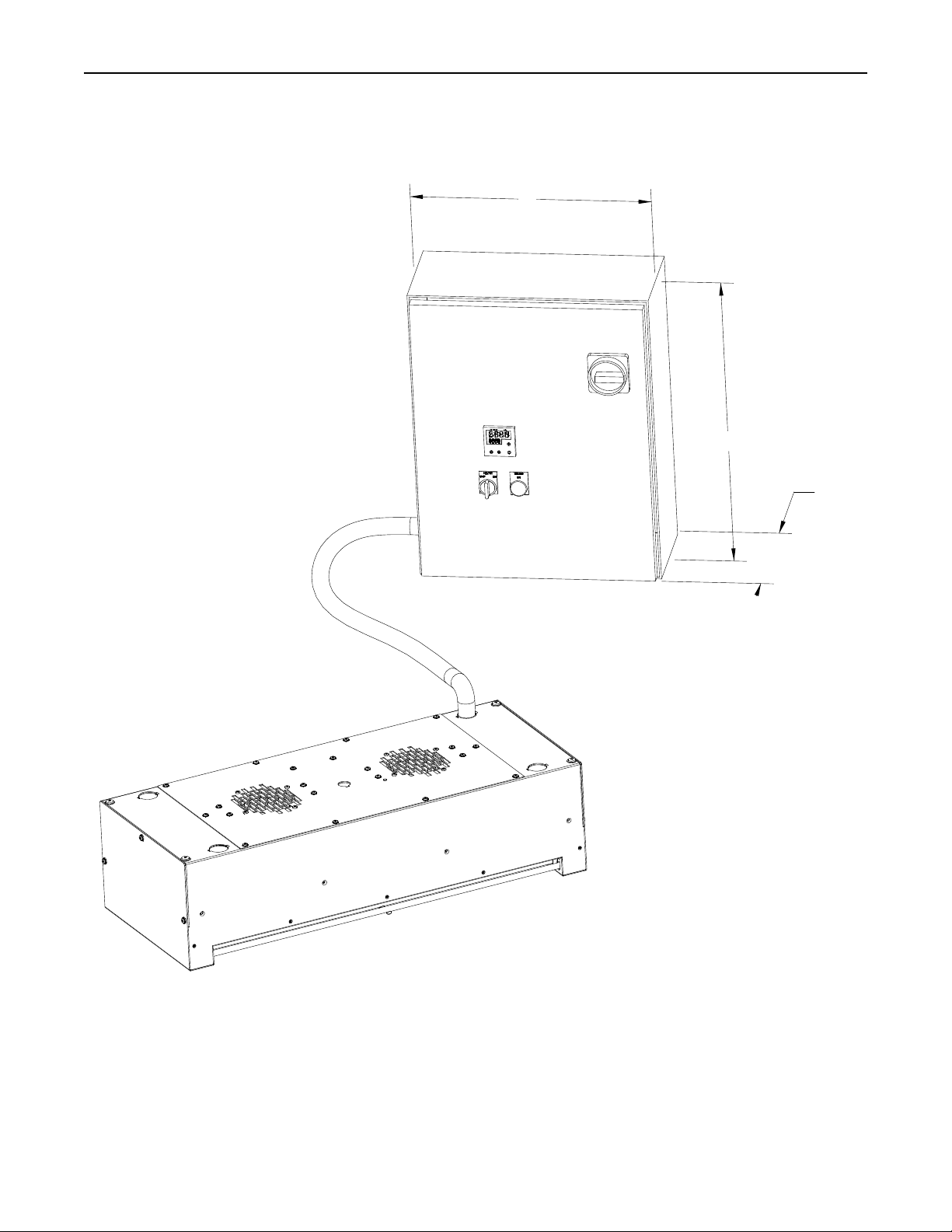
B
A
C
Research, Inc.
6
Page 10

Model 4555 PanelIRTM User Manual Product Description
Product Description-PanelIR 4555
Dimensions
B
16 inch
16 inch
16 inch
20 inch
24 inch
20 inch
24 inch
24 inch
8.62 inch
8.62 inch
8.62 inch
8.62 inch
12.62 inch
8.62 inch
12.62 inch
12.62 inch
Single Phase
Three Phase
Circuit Breaker Voltage Control Panel
20 amp 240 Volt Model 900-240-20
40 amp 240 Volt Model 900-240-40
60 amp 240 Volt Model 900-240-60
30 amp 224 Volt Model 925-240-30
60 amp 240 Volt Model 925-240-60
30 amp 480 Volt Model 925-480-30
60 amp 480 Volt Model 925-480-60
80 amp 480 Volt Model 925-480-80
A C
20 inch
20 inch
20 inch
20 inch
24 inch
20 inch
24 inch
24 inch
Control Options
All panels have an operator interface that allowed the heater to be controlled in any one of three operator selected modes.
Manual Operation
The digital control is used to directly set the percent output of the lamps from 0 to 100%.
Automatic-Temperature Control
The controller takes the input from a type “K” thermocouple or IR sensor and regulates the lamp output so the product temperature will
match the preset value.
Automatic-Line Speed
The controller will take the output from a 0 to 10 VDC line that references line speed and vary the lamp output from 0 to 100%
proportionally.
Once you have determined the appropriate size Model 4555 PanelIR Heater, please refer to the Power Controller to select the correct
controller for your application.
Research, Inc.
7
Page 11
Model 4555 PanelIRTM User Manual Product Description
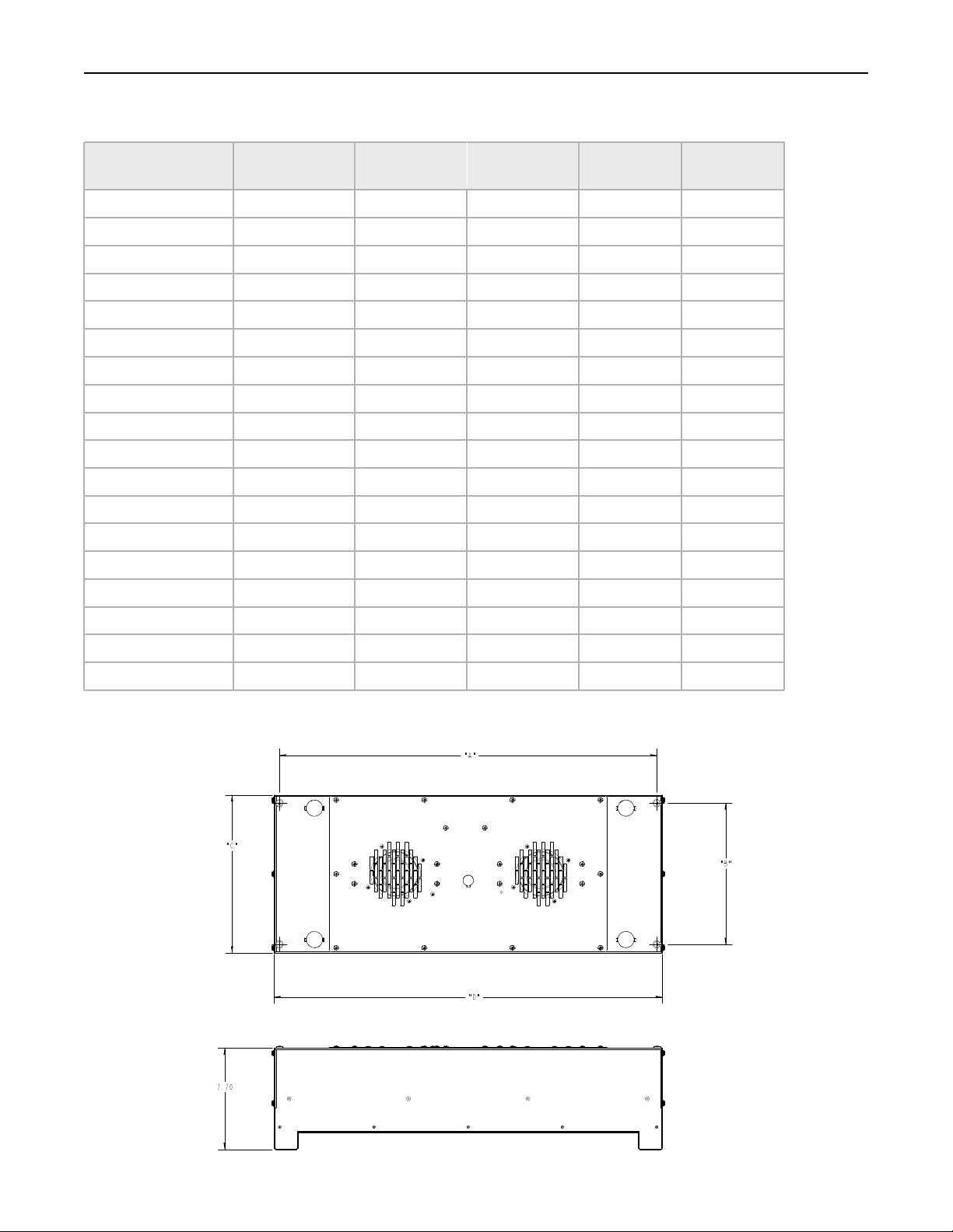
SPECIFICATIONS – PanelIR 4555
MODEL
Lighted
Length(in/mm)
Dimension
A
Dimension
B
Dimension
C
Dimension
D
9.41 6.00 5.38 8.58 5 (127) Model 4555-05-06
9.41 12.00 10.75 8.58 5 (127) Model 4555-05-12
14.41 6.00 5.38 13.58 10 (254) Model 4555-10-06
14.41 9.00 7.75 13.58 10 (254) Model 4555-10-09
14.41 12.00 10.75 13.58 10 (254) Model 4555-10-12
20.41 6.00 5.38 19.58 16 (406) Model 4555-16-06
20.41 9.00 7.75 19.58 16 (406) Model 4555-16-09
20.41 12.00 10.75 19.58 16 (406) Model 4555-16-12
29.41 6.00 5.38 28.58 25 (636) Model 4555- 25-06
29.41 9.00 7.75 28.58 25 (636) Model 4555-25-09
29.41 12.00 10.75 28.58 25 (636) Model 4555-25-12
Dimensions – PanelIR 4555
42.41 6.00 5.38 41.58 38 (965) Model 4555-38-06
42.41 9.00 7.75 41.58 38 (965) Model 4555-38-09
42.41 12.00 10.75 41.58 38 (965) Model 4555-38-12
Research, Inc.
8
Page 12
Model 4555 PanelIRTM User Manual Product Description
A
A
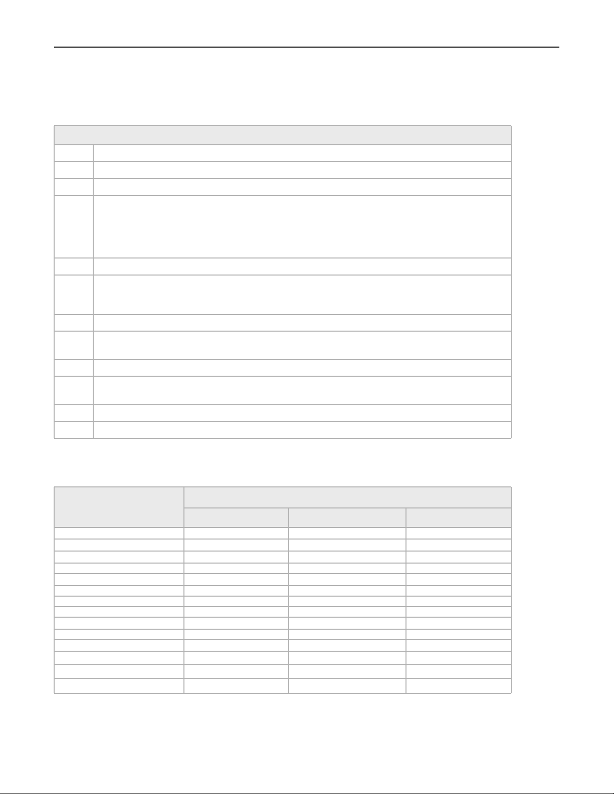
How to Order – PanelIR Model 4555
PRODUCT DESCRIPTIONS PanelIR Model 4555
Model
10
16
25
38
06
09
12
MW
SW
Description
PanelIR High Density Area Infrared Heater w / fan (s) Pressure Switch and Thermostat 4555
Length Code
5
5 inches (127mm)
10 inches (254 mm)
16 Inches (406 mm)
25 Inches (635 mm)
38 Inches (965 mm) Short wave lamps only
Lamp Width Code
6 Inches (152 mm)
9 Inches (229 mm)
12 Inches (254 mm)
Lamp Type Code
Medium-Wave
Watt-Short-Wave
Reflector Type Code
R
CR
luminum Reflector
Ceramic Reflector
Custom Options Code
None 00
* Example: 4555-05-06-SW-AR-00
2. Second – Specify the Power Controller
Heater Module
240 Volt 1 Phase
900-240-20 Model 4555-05-06
900-240-40 Model 4555-05-12
900-240-40 Model 4555-10-06
900-240-40 Model 4555-10-09
900-240-60 Model 4555-10-12
900-240-60 Model 4555-16-06
Model 4555-16-09
Model 4555-16-12
Model 4555-25-06
Model 4555-25-09
Model 4555-25-12
Model 4555-38-06
Power Controller
240 Volt 3 Phase
925-240-30
925-240-30
925-240-30
925-240-30
925-240-30
925-240-60
925-240-60
480 Volt 3 Phase
925-480-30
N/A
925-480-30
925-480-30
925-480-30
925-480-60
925-480-30
925-480-60 Model 4555-38-09
925-480-80 Model 4555-38-12
Research, Inc.
9
Page 13

Model 4555 PanelIRTM User Manual Product Description
Accessories & Replacement Parts – PanelIR 4555
ACCESSORIES AND REPLACEMENT PARTS PanelIR 4555
Description Model
Set of two edge reflectors for:
5 inch (127 mm) length ER-4555/4-05
10 inches (254 mm) length ER-4555/4-10
16 inches (406 mm) length ER-4555/4-16
25 inches (635 mm) length ER-4555/4-25
38 inches (965 mm) length ER-4555/4-38
Short Wavelength Lamps
5 inch, 500 watt 103390-001
10 inch, 1600 watt 103390-003
16 inch, 1000 watt 103390-005
25 inch, 2500 watt 103390-007
38 inch, 3800 watt 103390-010
Mounting
The back of the Model 4555 has four 1/4-20 X 1/2 inch screws installed for mounting purposes.
Optional Edge Reflectors
Edge reflectors are available to restrict the radiant energy to a rectangular area. The edge reflectors are constructed from the same
materials used in the heater modules. Edge reflectors are specified in the model number or as accessories (in pairs), ordered separately
from the Model 4555 heater. For arrays of multiple hookups, only one set of edge reflectors is required for the array.
Medium Wavelength Lamps
10 inch, 1000 watt 106656-001
16 inch, 1875 watt 106656-003
25 inch, 2500 watt 106656-004
Additional Operation Manual M4555
Research, Inc.
10
Page 14
Model 4555 PanelIRTM User Manual Installation
MECHANICAL
INSTALLATION
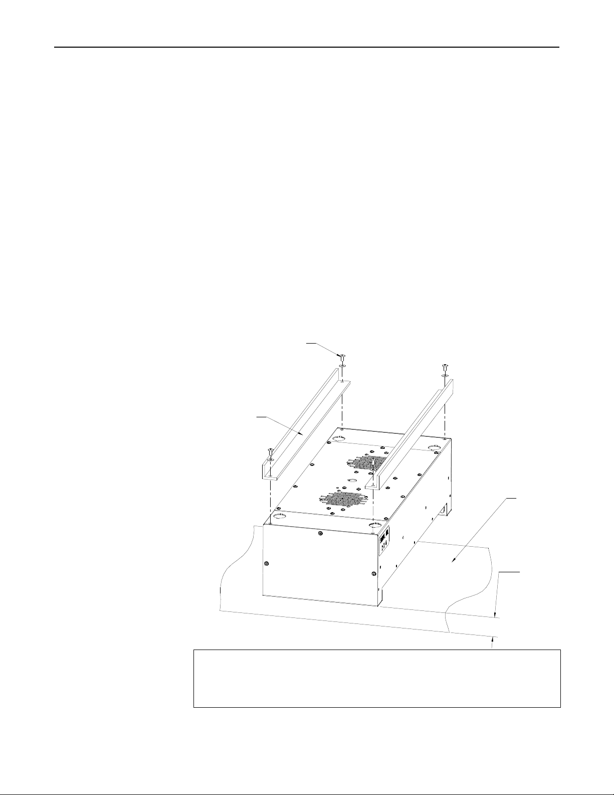
Figure 3-1 Typical
installation
drawing for
model 4555
heater.
Installation
Tools Required:
• Phillips Screwdriver
• Slotted Screwdriver
• Hammer
• Metal Punch
• Pliers
• Tape Measure
• Tin snips/Metal cutting scissors.
As shown in Figure 3-1, four ¼-20 screws are provided on the top of the Model 4555
heater for mounting purposes. The heater can be attached directly to a suitable frame
structure or mounting brackets using these four screws. The distance between the heater
and target should be determined before mounting the heater. The heater should be
mounted so that each end cover may easily be removed for lamp installation.
Multiple Model 4555 heaters can be mounted side-by-side to form large heating arrays.
Mounting
Screws (4X)
1/4 - 20
Frame
Target
Heater to
Target Distance
CAUTION!
The back and end covers of Model 4555 heaters should not be exposed to
temperatures exceeding 425°F (218°C). The heater should not be
surrounded or enclosed by any type of insulating material.
Research, Inc.
11
Page 15
Model 4555 PanelIRTM User Manual Installation
ELECTRICAL
INSTALLATION
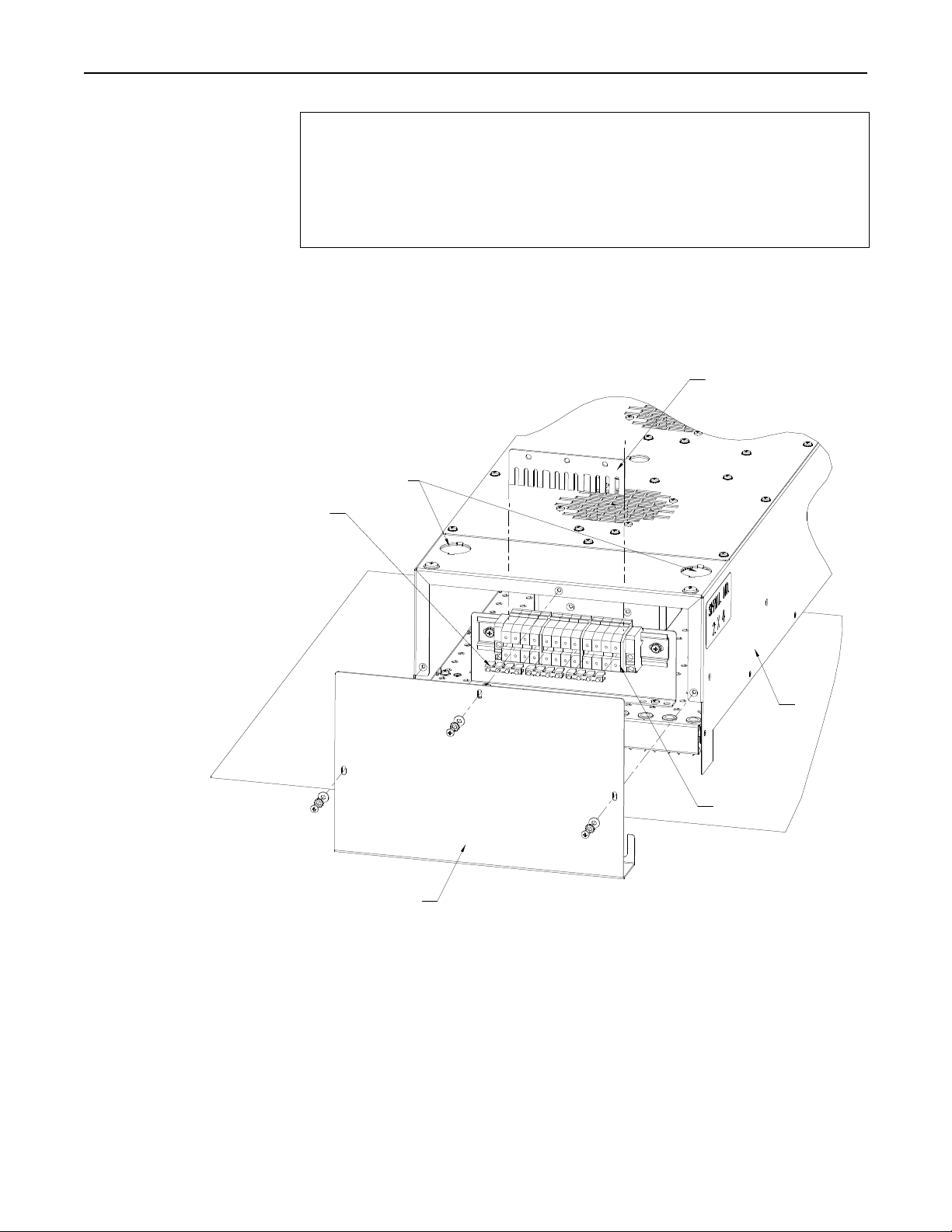
Figure 3-2 Terminal Strip
and Bus Bar
Jumper Bars (6X)
CAUTION!
All internal wiring of the model 4555 Panel IR should be high
temperature insulated wire as specified below or of an equivalent type:
• Lead wire type PFAH or TFE, 600V Maximum, 250°C maximum, UL
listed.
• Ampacity based on National Electrical Code Table 310.
As shown in Figure 3-2, the Model 4555 contains two electrical terminal blocks, one
each mounted on the internal heater housing, under each heater end cover. These
terminal blocks each contain contact points for electrical connection of each lamp of the
heater. In addition, each terminal strip contains a “bus bar” that provides electrical
connection between all contact points on the terminal block (Figure 3-2).
Electrical
"Knock-Outs"
End Cover (2X)
The presence of the bus and jumper bars on each terminal block allows the heater to be
easily wired in different configurations. A model 4555 heater wired in a single-zone
configuration is shown in Figure 3-3. In this configuration the lamps mounted in the
Model 4555 all simultaneously receive the same voltage from the power source. In this
case, electrical connection from each terminal block to the power source is made by a
single, high temperature grade, electrical wire as follows:
Bus Bar
Terminal Blocks
Heater
Housing
Research, Inc.
12
Page 16
Model 4555 PanelIRTM User Manual Installation
↔
←
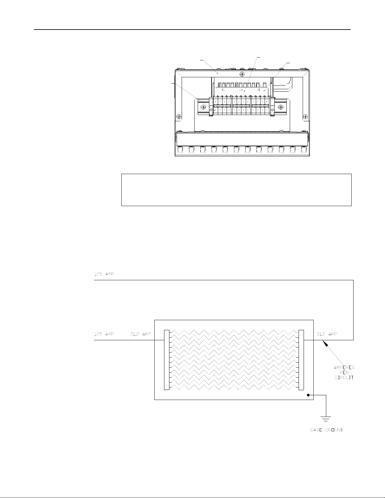
Figure 3-3 Single Zone
Wiring
Figure 3-4 Single Zone
Single Phase
Schematic
480 V
SINGLE
PHASE
↓
Heater
Incoming Power
Bus Bar
Terminal
Blocks
WARNING!
The electrical power required to operate the 4555 is extremely dangerous. Make sure
all electrical power that is to be provided to the Model 4555 is adequately turned off
prior to making any electrical connection to the heater.
NOTE:
The following instructions are for single-phase electrical wiring of the Model 4555. See
next section for three-phase wiring.
Research, Inc.
13
Page 17

Model 4555 PanelIRTM User Manual Installation
Single Phase Wiring
Prepare heater unit for wiring
Remove electrical connection
“knock-outs”
Install high temperature wire
Wiring Power to Heater
1. Remove the three screws from each of the end covers on each end of the heater
using the Phillips screwdriver.
2. Carefully remove each of the end covers and set them aside so that they are not
damaged.
1. Using the hammer and punch, remove one circular “knock-out” from each end of
the top of the heater by placing the metal punch on the knock-out outline and
striking the punch with the hammer until the knock-out protrudes into the heater.
2. Using the pliers, remove both knock-out slugs from the heater body.
3. Discard the knock-out slugs.
1. On each end, use the tape measure to measure the distance from the center of each
terminal block to the point at which the supply power and the high temperature
wire are to be joined.
2. Include additional length to account for wire travel through the knock-out hole and
enough to perform adequate wire stripping prior to attachment to the heater and
power supply wiring.
3. Cut two lengths of high temperature wire corresponding to the measured lengths.
4. Strip the insulation from each end of each wire to expose the conductor material
(approximately ½”)
5. Feed one wire (each) into the heater through each end of the heater between the
terminal blocks and the back of the heater and up through the knock-out hole.
Install the wires into the terminal blocks (see Figure 3-4).
6. If the amp draw is 50 amps or less, the stripped end of the wire can be inserted
directly into the terminal block. If it is greater than 50 amps, attach a ring lug to the
end of the wire and install the ring onto the bus bar with a screw and nut.
1. Attach the unconnected end of each high temperature wire to the power supply
wiring using appropriate wire joining techniques (as specified by local electrical
codes and standards).
Research, Inc.
14
Page 18

Model 4555 PanelIRTM User Manual Installation
Three Phase Wiring
Prepare heater unit for wiring
Remove electrical connection
“knock-outs”
Install high temperature wire
Wiring Power to Heater
1. Remove the three screws from each of the end covers on each end of the heater
using the Phillips screwdriver.
2. Carefully remove each of the end covers and set them aside so that they are not
damaged.
3. Remove the Bus Bars from the terminal blocks. Leave the jumper bars in place.
1. Using the hammer and punch, remove one circular “knock-out” from each end of
the top of the heater by placing the metal punch on the knock-out outline and
striking the punch with the hammer until the knock-out protrudes into the heater.
2. Using the pliers, remove both knock-out slugs from the heater body.
3. Discard the knock-out slugs.
1. On each end, use the tape measure to measure the distance from the center of each
terminal block to the point at which the supply power and the high temperature
wire are to be joined.
2. Include additional length to account for wire travel through the knock-out hole and
enough to perform adequate wire stripping prior to attachment to the heater and
power supply wiring.
3. Cut three lengths of high temperature wire corresponding to the measured lengths.
4. Strip the insulation from each end of each wire to expose the conductor material
(approximately ½”)
5. Feed one wire into the heater through one knock-out and two wires through the
other. Install the wires into the terminal blocks.
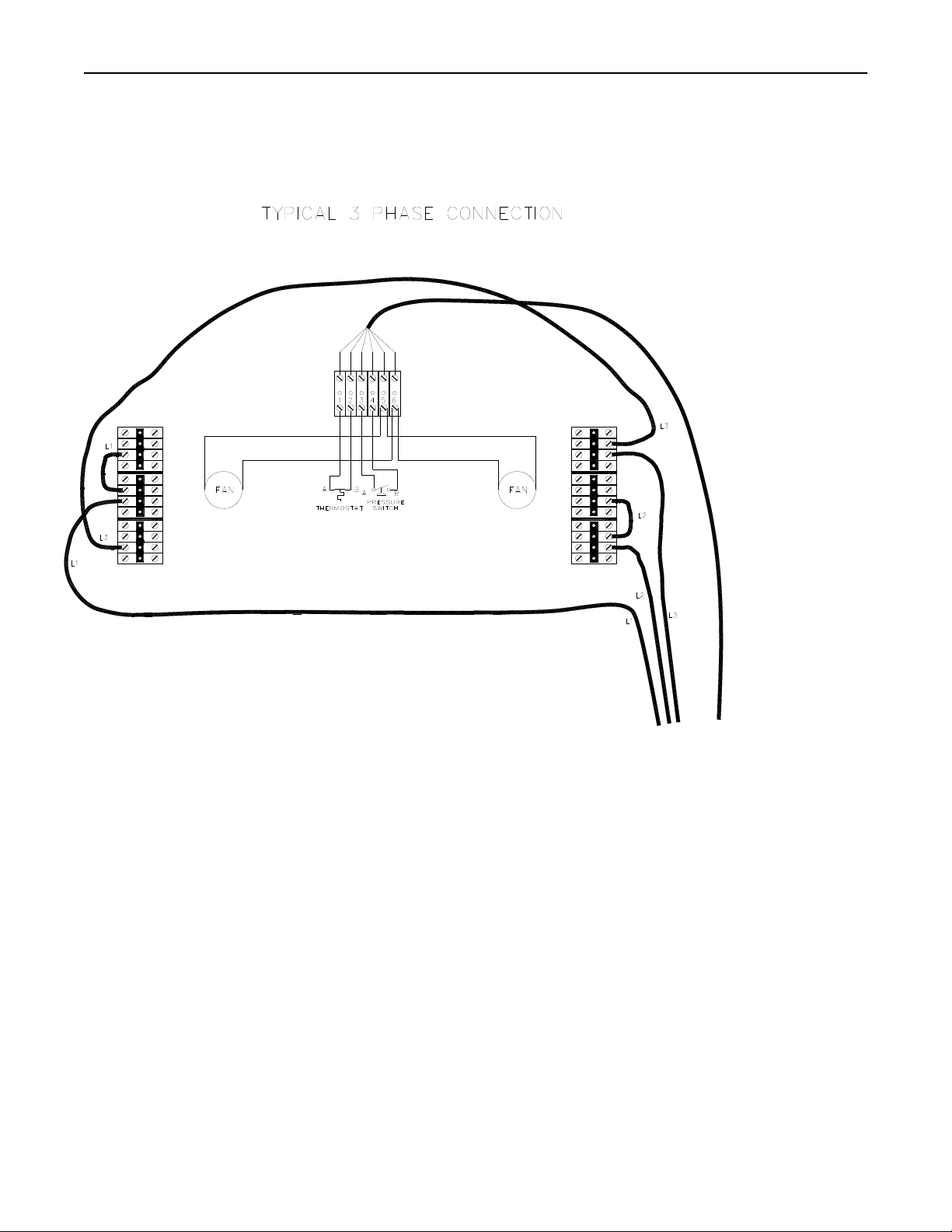
6. Jumper wires will need to be installed into the terminal blocks to complete the three
phase circuit (see Figure 3-5)
1. Attach the unconnected end of each high temperature wire to the power supply
wiring using appropriate wire joining techniques (as specified by local electrical
codes and standards).
Research, Inc.
15
Page 19
Model 4555 PanelIRTM User Manual Installation
Figure 3-5 Single Zone 3
Phase Wiring
Diagram
Research, Inc.
16
Page 20

Model 4555 PanelIRTM User Manual Installation
Multi-Zone Wiring
Prepare heater unit for wiring
Remove electrical connection
“knock-outs”
The Model 4555 can also be wired so that multiple heating zones are produced within
the heater. When configured for multi-zone operation, each zone of lamps is
electrically controlled by its own power control device. Wiring the Model 4555 for
multi-zone operation is as follows:
1. Remove the three screws from each of the end covers on each end of the heater
using the Phillips screwdriver.
2. Carefully remove each of the end covers and set them aside so that they are not
damaged.
1. Three knock-outs are provided on each end of the Model 4555. Multiple knock-
outs can be removed on each end of the heater so that an individual knock-out does
not have to accommodate more than three or four wires. It is left up to the installer
to determine the number of knock-outs to remove to simplify the wiring procedure.
2. Using the hammer and punch, remove one circular “knock-out” from each end of
the top of the heater by placing the metal punch on the knock-out outline and
striking the punch with the hammer until the knock-out protrudes into the heater.
3. Using the pliers, remove the knock-out slugs from the heater body.
4. Discard the knock-out slugs.
1. Using the slotted screwdriver, loosen the screws holding the bus bar in the terminal
blocks.
2. Lift the bus bar out of the terminal strip.
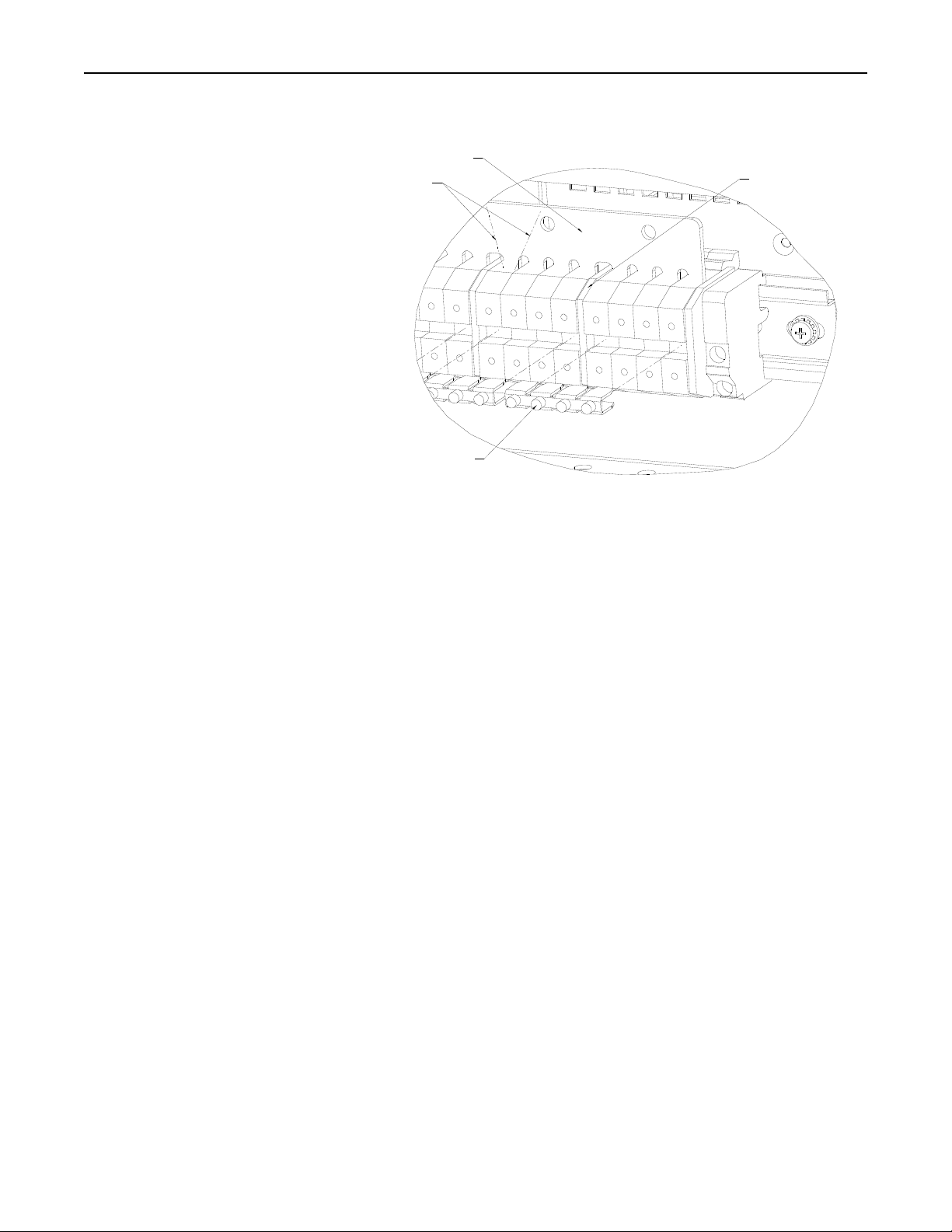
3. As shown in Figure 3-6, the bus and jumper bars can be cut to produce shorter,
individual jumpers corresponding to the number of desired heating zones. For
zones with more than 4 lamps, cut the bus bar the desired length. Use the jumper
bars for zones with 4 lamps or less. Move the plastic spacers so that they are
between the terminal blocks for each zone. They are required to insure electrical
isolation between zones.
4. Tighten each of the screws in the terminal blocks and jumper bars.
Research, Inc.
17
Page 21
Model 4555 PanelIRTM User Manual Installation
Figure 3-6 Multi-Zone Bus
Bar Preparation
Install high temperature wire
Wiring Power to Heater
REMOVE THIS
6-LAMP BUS
CREATE 2
BUS BAR
PLASTIC SPACER
AREA TO
BARS
JUMPER BAR
1. On each end, use the tape measure to measure the distance from the center of each
terminal strip ‘zone’ to the point at which the supply power and the high
temperature wire are to be joined.
2. Include additional length to account for wire travel through the knock-out hole and
enough to perform adequate wire stripping prior to attachment to the heater and
power supply wiring.
3. Cut lengths of high temperature wire corresponding to the measured lengths.
4. Strip the insulation from each end of each wire to expose the conductor material
(approximately ½”).
5. Feed the wires into the heater through each end of the heater between the terminal
strip and the back of the heater and up through the knock-out holes.
6. If the amp draw is 50 amps or less, the stripped end of the wire can be inserted
directly into the terminal block. If it is greater than 50 amps, attach a ring lug to the
end of the wire and install the ring onto the bus bar with a screw and nut.
Attach the unconnected end of each high temperature wire to the power supply wiring
using appropriate wire joining techniques (as specified by local electrical codes and
standards).
Research, Inc.
18
Page 22
Model 4555 PanelIRTM User Manual Installation
Lamp Installation
Lamp Mounting
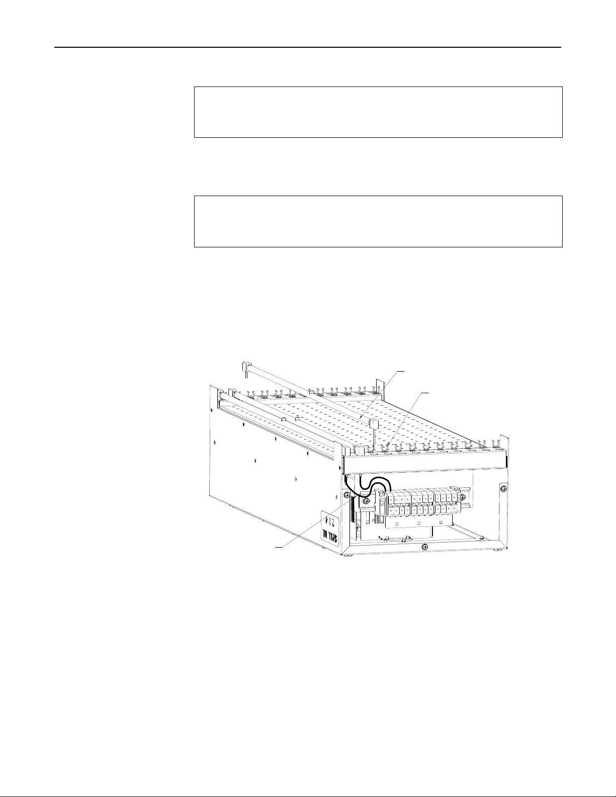
Figure 3-7 Lamp installation
CAUTION!
Wear soft, clean, oil free flannel or plastic gloves when handling halogen, quartz lamps.
Oils and contaminates are readily transmitted to the quartz by unprotected hands and
can cause premature lamp failure.
1. Insert the lamp lead wires through the reflector and snap the lamp into the spring
clips provided (Figure 3-7). If the lamp clips are excessively tight, gently spread
the clip wider. Make sure that the lamp is held securely in the clip.
CAUTION!
It is important that the lead wire between the lamp and terminal block not be pulled tight
when the lamp is installed. As the heater module and lamps heat and cool, they are also
expanding and contracting which may damage the lamp if the lead is too tight.
2. Insert the lamp lead wire into terminal blocks and tighten the screw terminal. Make
sure that the terminal block is not tightened on the insulation of the wire.
3. When all of the lamps have been installed, check for electrical shorts to the heater’s
metal chassis
LAMP LEAD WIRE
4. Carefully replace each end cover in its proper location on the heater body.
5. Insert the three screws that hold the end cover in place into their respective holes
and tighten them into the heater using the Phillips screw driver
LAMP
LAMP CLIP
Research, Inc.
19
Page 23
Model 4555 PanelIRTM User Manual Installation
Wiring Thermostat
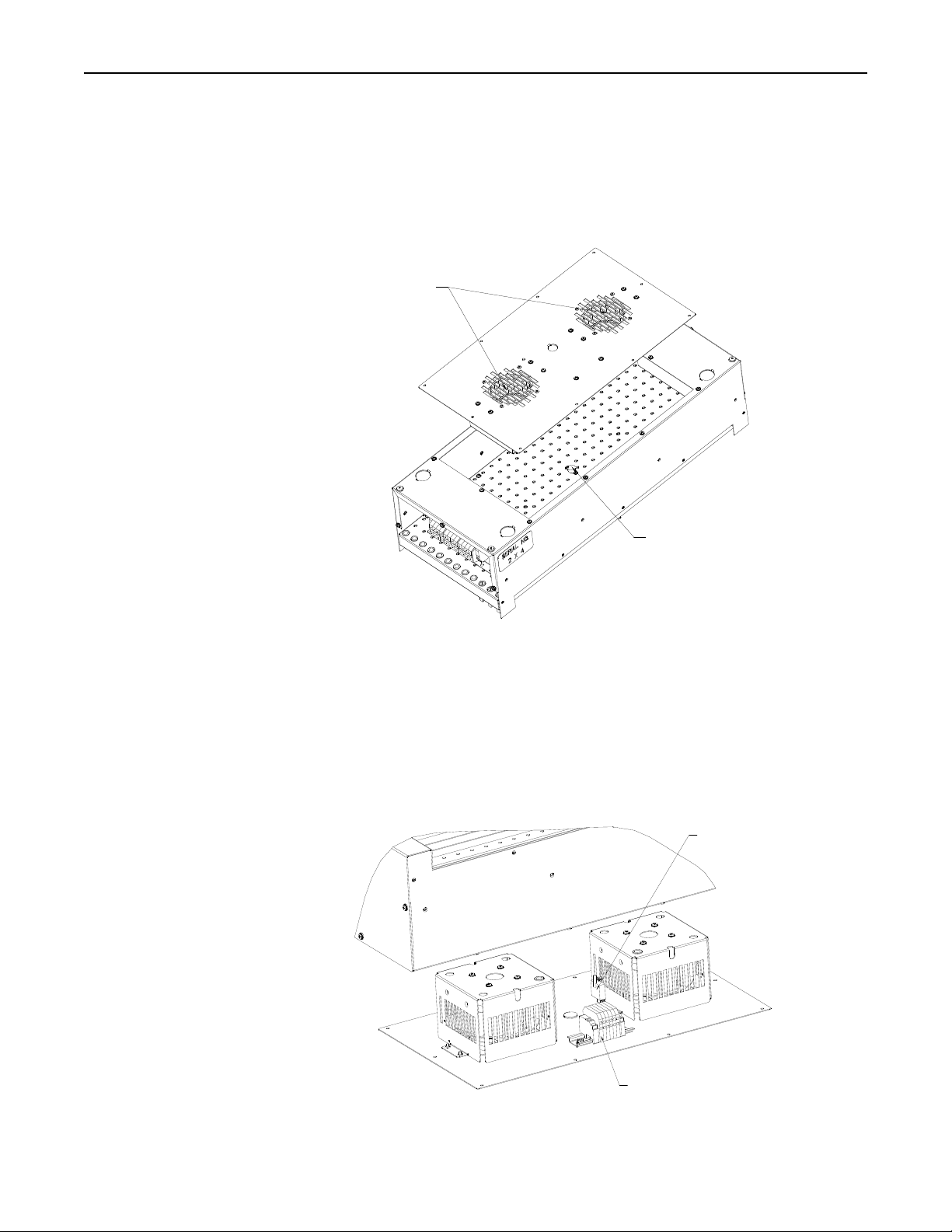
Figure 3-8 Thermostat wiring
Pressure Switch Wiring
Figure 3-9 Pressure Switch
Thermostat, and
Blower Wiring
A thermostat is mounted to the backside of the Model 4555 air plenum inside the heater
body (Figure 3-8). The thermostat is a feature of the model 4555 that safeguards the
heater from overheating. The thermostat is rated for 120 volt 15 amp service. When
properly wired to the heater power control system, the thermostat will trip if it reaches a
temperature of 180° F (82° C) resulting in loss of power to the heater if wired to operate
in this configuration. The thermostat will reset after it cools below a temperature of
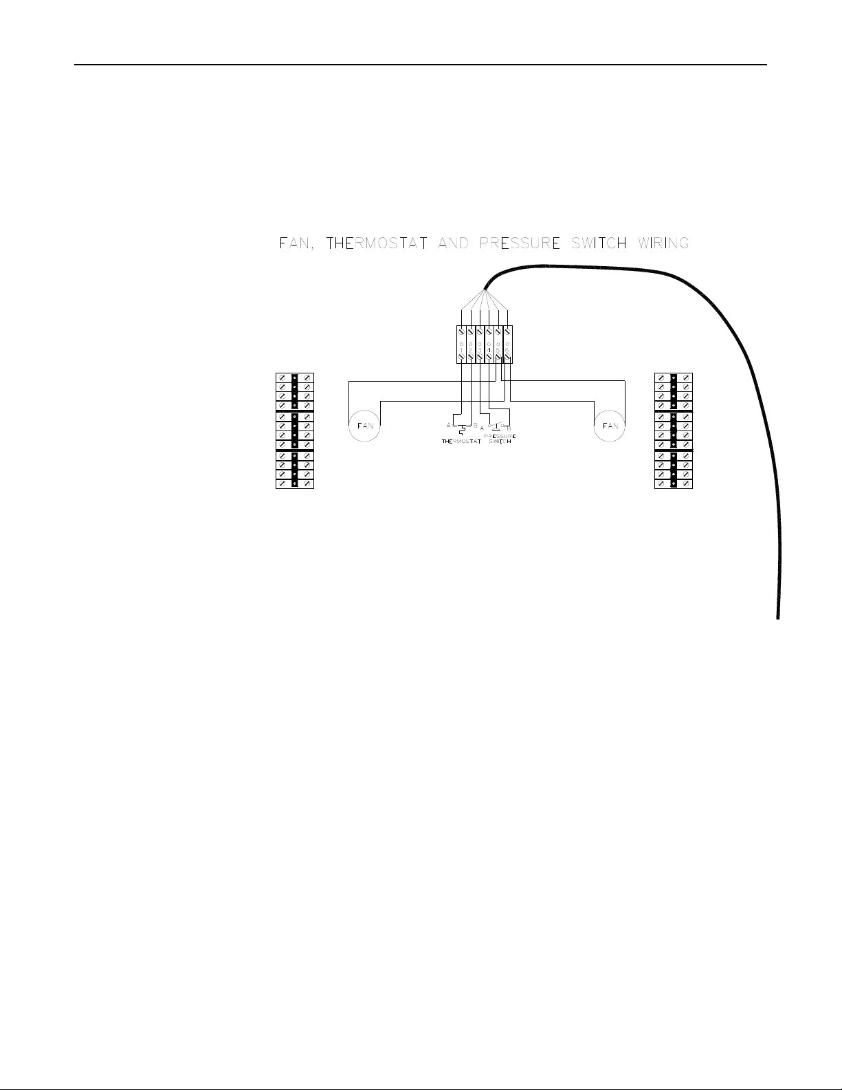
150° F (66° C). The thermostat is wired to terminal blocks 1-2 (Figures 3-9,10).
Blowers
Thermostat
A pressure switch is mounted to the fan bracket inside the heater body (Figure 3-7).
The pressure switch is a feature of the Model 4555 that safe guards the heater from loss
of cooling air. The pressure switch is rated for 24 VDC, 20-ma service. When properly
wired to the heater power control system, the pressure switch will trip if the heater body
losses pressure due to blower stoppage or intake clogging, resulting in loss of power to
the heater. The pressure switch will reset when blower function resumes. The Pressure
switch is wired to terminal blocks 3-4 (Figures 3-9,10).
Pressure Switch
Terminal Blocks
Research, Inc.
20
Page 24
Model 4555 PanelIRTM User Manual Installation
Forced Air Blower
Wiring
Figure 3-10 Blower,
Thermostat and
Pressure Switch
Wiring Diagram
The Model 4555 has an integral blower to provide cooling air to the lamps and
reflectors. The blowers operate on 230 VAC 50/60 Hz. The blowers are wired to
terminal blocks 5-6 (Figures 3-9,10). All applicable electrical standards and codes must
be followed when wiring the forced air blowers.
Research, Inc.
21
Page 25

Model 4555 PanelIRTM User Manual Operating Instructions
Operating Instructions
Operation of the Model 4555 is relatively straightforward once installed and properly
(electrically) wired to an appropriate power control source. In addition, the forced-air
blower system, pressure switch and heater thermostat must be connected to an
appropriate power supply in order to operate.
The intensity of the infrared energy generated by the lamps is directly proportional to
the amount of electrical power supplied to the lamps. Determining the amount of
electrical power supplied to the lamps in the Model 4555 depends on a variety of
parameters including (but not limited to):
• Infrared absorptivity of target product (e.g. Target material properties
including: color, surface condition, and temperature).
• Desired product heating rate.
• Minimum/maximum target product temperature.
• Distance from heater to target product.
• Speed of target product moving through the heating area.
In general, a limited number of experimental tests to determine the optimal settings (i.e.
heater-to-target distance, applied power to the lamps, product target speed through the
heating area, etc.) should be performed for any Model 4555 installation. Following this
approach will yield the best operational settings for a given application.
Depending on the application (and if feasible), a temperature control feed back system
may be used to control the energy output of the Model 4555. A typical control system
includes power control, temperature measurement capability, target product tachometer
feed back (moving target applications), and alarm/emergency shut down capability.
Employing such a system allows for continuous monitoring of the heating process and
ensures continuous, steady state infrared energy output from the heater.
Beyond routine, periodic maintenance (See Section 5—Maintenance) and following all
safety practices (See Section 1—Safety) the Model 4555 requires no additional care or
handling for correct, efficient operation.
Research, Inc.
22
Page 26

Model 4555 PanelIRTM User Manual Maintenance Instructions
Maintenance
Periodic inspection for dirt and contaminates on the heater, blower mechanism, and
lamps, and removal of such, will ensure that the Model 4555 continues to operate
efficiently and will extend lamp life.
In dirty environments or heating operations the lamps may become contaminated by,
dust, fingerprints or other foreign matter. When this occurs it is recommended that they
be cleaned using the following procedure:
WARNING!
Disconnect all power running to the Model 4555 from the power source and allow the
heater to cool at least five minuets before continuing.
CAUTION!
Wear soft, clean oil-free flannel or plastic gloves when handling quartz lamps. Skin oils
and other contaminant can cause premature lamp failure if they are allowed to reside on
the quartz lamp.
Using a soft, dry, cloth or tissue, wipe the residue from contaminated lamps. A solution
of household strength ammonia and water can be used as a solvent.
The reflector for the Model 4555 heater is made from either polished aluminum or a
high temperature ceramic material. The ceramic reflector is essentially self-cleaning.
Surface heat normally prevents contaminant condensation on the reflector. Increasing
power to the lamp for short time periods will increase the heater temperature resulting in
the removal of most contaminates.
The aluminum reflector can be maintained by cleaning with a soft cloth or tissue. If the
reflector gets scratched or dull, it can be polished with aluminum polish.
Research, Inc.
23
Page 27

Model 4555 PanelIRTM User Manual Appendix A
Appendix A
DETERMINING THE
CURRENT PER LAMP
Multiple Heater Wiring
1. Calculate the percentage of the applied voltage to the lamp’s rated voltage:
Percent Voltage =
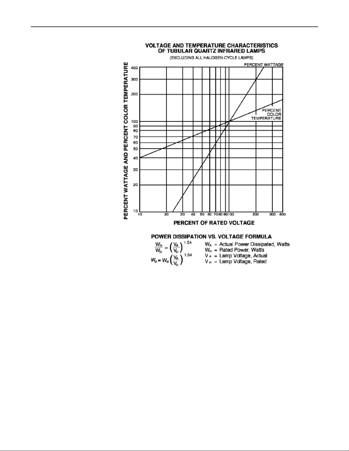
2. Use Figure A-1 to determine the percent of power dissipated by the lamps at that
percent voltage. Or for greater accuracy, calculate the percent of power
dissipated:
Percent of Power Dissipated = (Percent Voltage)
3. Determine the power dissipated:
Dissipated Power = Percent of Power Dissipated X Rated
Power
4. Calculate the lamp current:
Lamp Current =
Example: Assume a 3800 T3, 3800 watt, 570 volt lamp is to operate in a 440 volt
line.
1. Percent Voltage = = 77%
2. The percent-dissipated power at 77% of rated load is about 67%. Or to calculate:
Percent of Power Dissipated = (.77)
3. Dissipated Power = 67% Percent of Power Dissipated X 3800 Watts = 2546 watts
4. Lamp Current = = 5.78 Amperes
440 Applied Voltage X 100
570 Rated Voltage of Lamp
2546 Watts Dissipated Power
440 volts Applied Voltage
Applied Voltage X 100
t
Ra ed Voltage of Lamp
Dissipated Power
Applied Voltage
1.54
= 66.8% or 67%
1.54
Research, Inc.
24
Page 28
Model 4555 PanelIRTM User Manual Appendix A
Figure A-1 Voltage and
Temperature
Single Phase Loads
The line current for single-phase loads can be calculated using one of the following
methods:
1. Determine the current per lamp. If the applied voltage to the lamps is different,
calculated the lamp current as explained on page 21.
2. Determine the number of lamps.
3. Calculate the line current:
Line Current = Lamp Current X Number of Lamps.
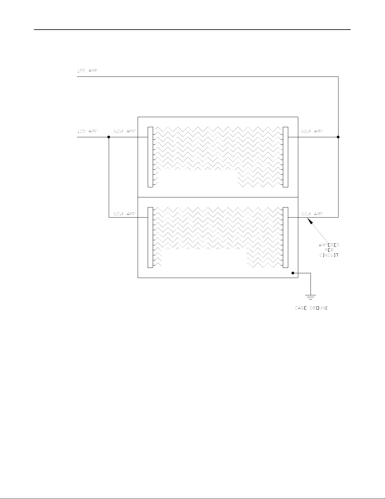
Example: Assume quantity 2 Model 4555-25-12 using 2500 T3 lamps connected to a
480 volt source (see Figure A-2).
1. The current per 2500T3 lamp connected to a 480 volt source is 5.2 amperes.
2. The number of lamps in each Model 4555-25-12 is 12. Quantity 2 Pyropanels X
12 Lamps = 24 lamps total (see Figure A-2).
3. Line Current = 5.2 Amperes X 24 Lamps = 125 Amperes.
Research, Inc.
25
Page 29
Model 4555 PanelIRTM User Manual Appendix A
↔
←
Figure A-2 Single-Phase or DC Input
Wiring Diagram
480 V
SINGLE
PHASE
↓
MODEL 4555-25-12
(12) 2599T3 LAMPS
MODEL 4555-25-12
(12) 2599T3 LAMPS
Research, Inc.
26
Page 30

Model 4555 PanelIRTM User Manual Appendix A
Three Phase Balanced Loads
A three-phase load is one where the load for all three phases dissipates the same power.
In the case of the Model 4555, there should be an equal number of the same wattage
lamps connected to each phase.
The line current for three phase loads can be calculated using one of the following
methods:
1. Determine the power dissipated per lamp.
2. Determine the number of lamps.
3. Calculate the total power dissipated in the load.
4. Calculate the line current:
Line Current =
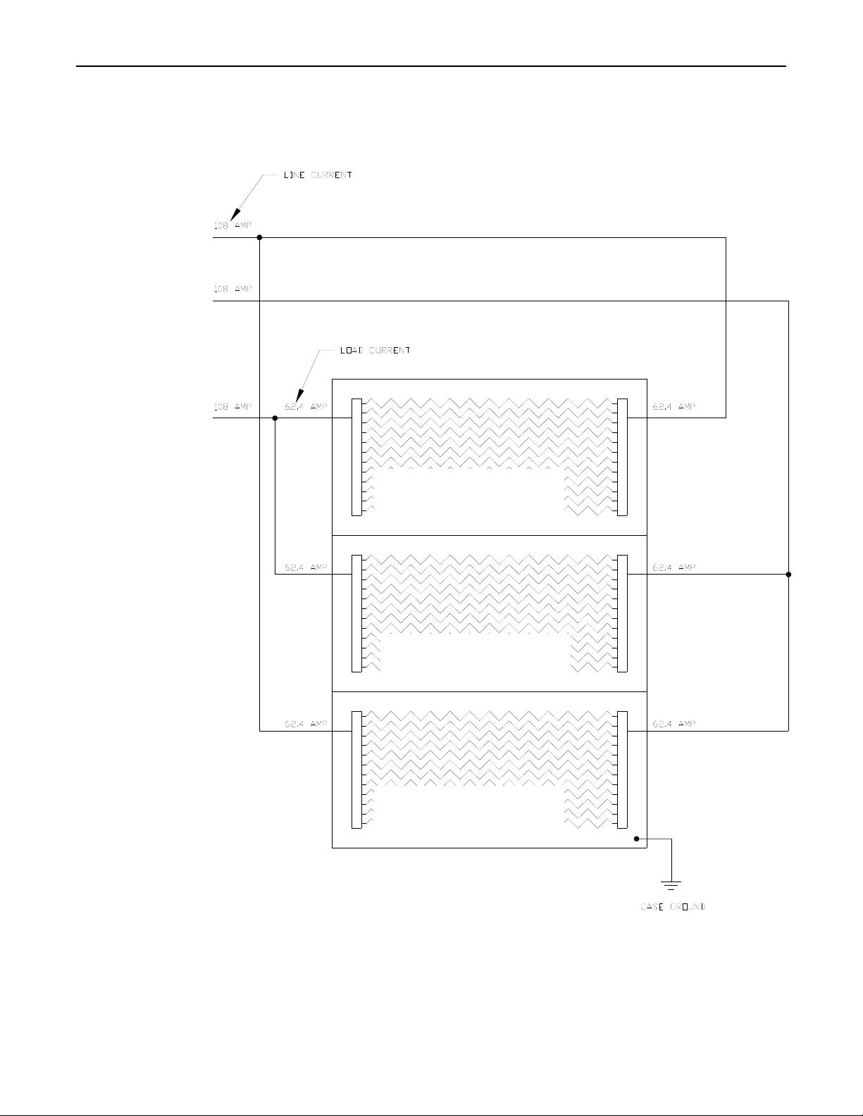
Example: Assume quantity 3 Model 4555-25-12 using 2500T3 lamps connected to a
480 volt source (see Figure A-3).
1. The power dissipated by a 2500T3 lamp is 2.5 kW, or 2500 watts, when
connected to a 480 volt source.
2. The number of lamps in each Model 4555-25-12 is 12. Quantity 3 Pyropanels X
12 lamps = 36 lamps total.
3. Load power = 2,500 Watts dissipated per lamp X 36 lamps = 90,000 Watts
4. Line Current = = 108 Amperes.
90,000 Watts Load Power
480 Volts Applied X 1.73
Load Power
Applied Voltage X 1.73
Research, Inc.
27
Page 31
Model 4555 PanelIRTM User Manual Appendix A
↔
←
Figure A-3 Balanced Three-Phase
Load Wiring Diagram
480 VOLT
3 PHASE
↓
MODEL 4555-25-12
(12) 2599T3 LAMPS
MODEL 4555-25-12
(12) 2599T3 LAMPS
MODEL 4555-25-12
(12) 2599T3 LAMPS
Research, Inc.
28
Page 32

Model 4555 PanelIRTM User Manual Appendix A
Three-Phase Unbalanced
Loads
Often it is not possible to connect the lamps in the Model 4555 to make a balanced
load. In this case, the three line currents supplying the heater lamps can be calculated
as follows:
1. Determine the number of lamps in each load.
2. Determine the current per lamp.
3. Calculate the load current for each of the three loads based on the number of
lamps in each load and the current per lamp.
Line current = Lamp Current x Number of Lamps in Load.
4. Calculate the line current based on the current of the two loads connected to the
line:
Line Current = √(FLC
2
+ (FLC x SLC) + SLC2)
NOTE:
FLC = First Load Current
SLC = Second Load Current
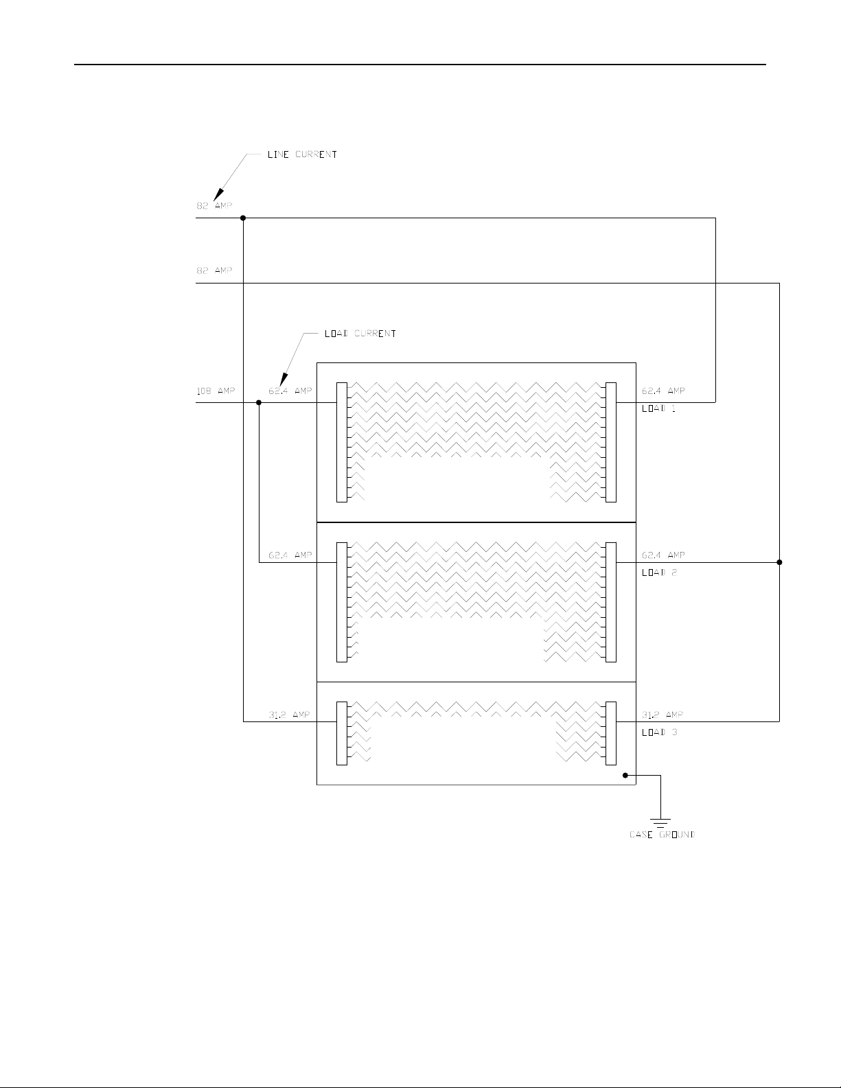
Example: Assume quantity 2 Model 4555-25-12 and quantity 1 Model 4555 25-06
using 2500T3 lamps connected to a 480 volt source (see Figure A-4).
1. Number of lamps in each load
Load 1 = 12 lamps
Load 2 = 12 lamps
Load 3 = 6 lamps
2. The current per 2500T3 lamp connected to a 480 volt source is 5.2 amperes.
3. Load Current 1 – 5.2 Amperes x 12 Lamps = 62.4 Amperes
Load Current 2 – 5.2 Amperes x 12 Lamps = 62.4 Amperes
Load Current 3 – 5.2 Amperes x 6 Lamps = 31.2 Amperes
4. Line Current 1 = √(LC1
Line Current 2 = √(LC2
Line Current 3 = √(LC1
2
+ (LC1 x LC3) + LC32) = √(62.42 + (62.4 x 31.2) + 31.22)
2
+ (LC2 x LC3) + LC32) = √(62.42 + (62.4 x 31.2) + 31.22)
2
+ (LC1 x LC2) + LC22) = √(62.42 + (62.4 x 62.4) + 62.42)
Research, Inc.
29
Page 33
Model 4555 PanelIRTM User Manual Appendix A
↔
←
Figure A-4 Unbalanced
Three-Phase Load
Wiring Diagram
480 VOLT
3 PHASE
↓
MODEL 4555-25-12
(12) 2599T3 LAMPS
MODEL 4555-25-12
(12) 2599T3 LAMPS
MODEL 4555-25-06
(6) 2599T3 LAMPS
Research, Inc.
30
 Loading...