

Page 1
Instruction Manual
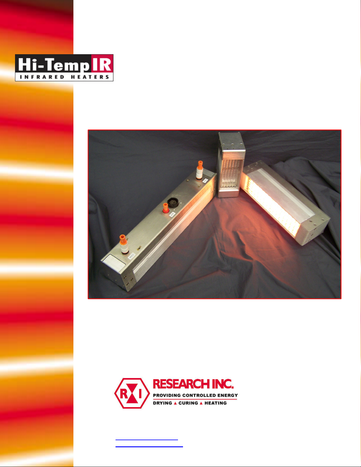
HiTempIR Heater
Model 5209
November, 2008
Another quality product from:
7128 Shady Oak Road • Eden Prairie, MN 55344
(952) 949-9009 Fax (952) 949-9559
Page 2

Page 3

Contents
Contents .................................................................................................................................. 1
1. Introduction ............................................................................................................................. 1
General Description .................................................................................................................... 1
Heater Module ........................................................................................................................ 1
Water Cooling ......................................................................................................................... 1
Air Cooling ............................................................................................................................. 1
Removable Electrical Cable .................................................................................................... 1
Heater Safety ........................................................................................................................... 2
Optional Quartz Window ........................................................................................................ 2
Optional Electrical Junction Box ............................................................................................ 2
Optional Power Control System ............................................................................................. 2
Standard Features ........................................................................................................................ 3
Contents
Rapid Response ....................................................................................................................... 3
Continuous Operation ............................................................................................................. 3
Controllable Energy Output .................................................................................................... 3
2. Safety ...................................................................................................................................... 4
GENERAL .................................................................................................................................. 4
High Temperatures.................................................................................................................. 4
Electrical Safety ...................................................................................................................... 5
Fire Safety ............................................................................................................................... 5
3. Installation............................................................................................................................... 6
Unpack and Check for Damage .................................................................................................. 6
Mounting the Heater ................................................................................................................... 6
4. Operating Instructions ............................................................................................................. 8
Heater Cooling Connections ....................................................................................................... 8
Electrical Connections ................................................................................................................ 9
Heater Thermostat ..................................................................................................................... 10
5. Maintenance & Troubleshooting .......................................................................................... 12
Quartz Window Cleaning and Replacement ............................................................................. 14
Cleaning the Reflector .............................................................................................................. 14
6. Dimensions and Specifications ............................................................................................. 15
7. Spare & Replacement Parts .................................................................................................. 19
Page 4

Page 5
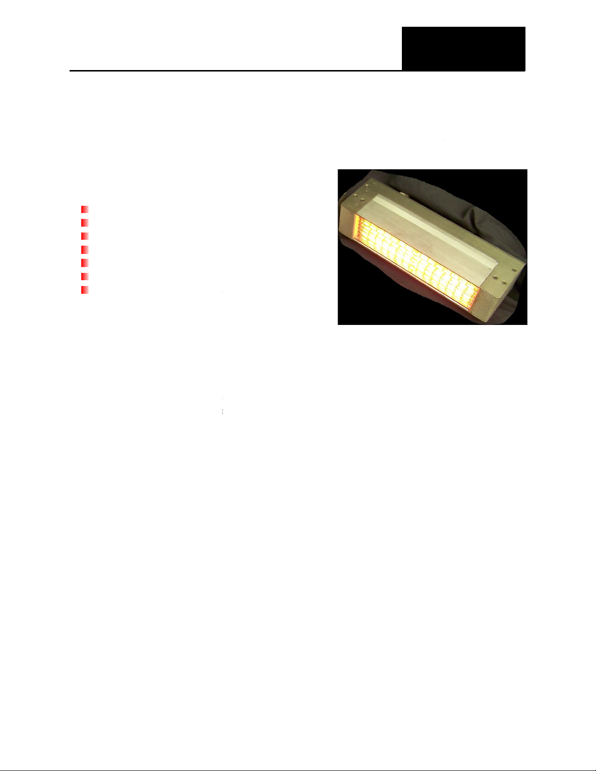
Typical applications for these heaters include:
Aerodynamic heating simulation
Heating tensile and fatigue test specimens
Semiconductor wafer processing
brazing processes
The Model 5209 includes the following major components:
The heater consists of a specular aluminum reflector that directs the infrared energy generated
3 style’, quartz halogen lamps factory
, and 16
5209. Additional lamps can be ordered separately from the heater.
te cooling water is required during operation of the Model 5209. Flexible tubing and
plumbing fittings are supplied with each heater for easy installation. Required cooling water
es are listed in Specifications, Section 6.
ir cooling must also be supplied to the heater for proper operation. This cooling
air removes excess heat from around the lamp end
plumbing hardware is included with each heater. Required airflow rates and pressures are
, Section 6
The Model 5209 heater is electrically wired from the T3 lamps to intermediate terminal blocks
within the heater. Further wiring from each terminal block to a pinned connector on the top of
e heater is also included. A 10
heater that is designed to mate with the heater’s pinned connector. This cable is designed for
installation within an electrical junction box (optional item) or inst
intensity infrared heat onto
installed in the heater.
, and 406 mm) are offered for the Model
seals. Flexible tubing and matching
ft. (3 m) removable electrical cable is supplied with each
alled within an appropriately
Section 1
1. Introduction
General Description
The Model 5209 Hi-TempIR
localized areas.
Thermal stress testing
Chemical processing
Stress relieving
Metal
Heater Module
®
heater is designed to provide high-
by six ceramic end-seal, ‘THeated lengths of 5-, 10-
Water Cooling
Adequa
flow rat
Air Cooling
Compressed a
listed in Specifications
Removable Electrical Cable
th
designed power source.
-
-inches (127-, 254-
-
.
-
1
Page 6

Heater Safety
An integrated thermostat is mounted to the backside of the aluminum reflector. The thermostat
is wired to the pinned connector with corresponding wiring residing in the removable electrical
cable. When wired into an appropriately designed power source, the normally closed
thermostat will open upon reaching an overheat condition preventing electrical power from
reaching the heater. The thermostat will close once the heater cools down to a safe operating
temperature.
Optional Quartz Window
A quartz window can be ordered along with each size of the Model 5209. When installed in the
heater, the quartz window protects the aluminum reflector and lamps from contaminants
released in the heating process resulting in maximum efficiency of the heater.
Optional Electrical Junction Box
An optional electrical junction box can be ordered with the Model 5209. The junction box
accommodates all of the wiring present within the removable electrical cable and is designed
to accept either a 240- or 480-volt supply source.
Optional Power Control System
The Model 5209 can be ordered with the ‘PC’ option. This configuration consists of the heater,
removable electrical cable wired to a junction box and a Research Inc. Model 915 (singlephase) or Model 935 (three-phase) SCR-based power control system, also wired to the
junction box. This power control system is designed to match the electrical supply needs of the
heater. Please see the Model 915 or Model 935 ControlIR® product data sheet for further
detail.
2
Page 7

Standard Features
The design and functionality of the Model 5209 supplies a variety of features and related
benefits:
Rapid Response
The quartz halogen lamps heat up and cool down instantly in response to power control
signals. They reach 90 percent of full operating temperature within three seconds of a cold
start. The radiant energy dissipates to ten percent five seconds after the power supply is
disconnected.
Continuous Operation
The formed stainless steel and extruded aluminum construction of the Model 5209 combined
with the liquid and air-cooling, allows the heater to withstand continuous high temperature
operation.
Controllable Energy Output
The infrared energy emitted from the heater can be adjusted to match the heating
requirements of a variety of applications.
The Model 5209 ordered with the ‘PC’ option is a complete heating solution designed with a
number of features including heater on/off control switching, potentiometer local control, and
mechanically interlocked doors with main power disconnect switch. Heater over-temperature
indicators, a digital voltmeter and system cooling on/off control switches with indicator lamps
are also included.
The complete system allows the end user to easily install both the heater and controller within
the given application. The heater is supplied with a 10-foot (3m) removable electrical cable and
is terminated within Model 5209 Junction Box. A separate 30-foot (9.1 m) electrical cable
connects the Junction Box to the power control system (either the Model 915 or Model 935
ControlIR®). This ‘plug and play’ feature simplifies installation for the end user and allows the
heating system to be put into use very quickly.
3
Page 8
Section 2
2. Safety
GENERAL
The Model 5209 heater is designed for safe operation. Nevertheless, installation,
maintenance, and operation of the heater can be dangerous for a careless operator or
maintenance person. For your safety and the safety of others, read the instructions in this
Instruction Manual and follow these safety practices to help prevent accident or injury.
! INFRARED RADIATION – CAUTION !
Continuous exposure to high intensity infrared radiation at close proximity could be harmful to
eyes or skin. Although infrared lamps emit negligible ultra violet electromagnetic radiation,
harmful burns can still result if an operator is in close contact with lamps being operated at
high intensity.
Because of the brilliant light emitted by infrared lamps at full intensity, it is recommended that
eyes be shielded from the glare if observing the lamps or radiant heat chamber for an
extended period of time. Use suitable shaded lenses or dark glasses.
High Temperatures
Parts of the heater may exceed 500°F (260°C). Contact with the lamps, reflectors, or metal
parts near the lamps may cause severe burns. In addition, extremely hot exhaust air is
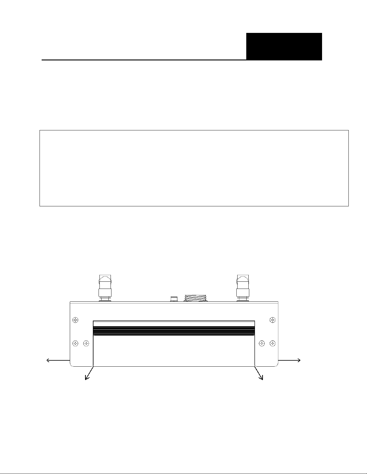
generated during operation of the Model 5209. Figure 2-1 depicts areas on the heater from
which the exhaust air will leave the heater.
Figure 2-1
4
Page 9

!WARNING!
NEVER place hands under or in front of the heating elements.
ALWAYS allow heating element to cool at least three minutes
before touching the lamps or adjacent parts.
Electrical Safety
There is danger of electrical shock when servicing the heater.
!CAUTION!
Observe all applicable local and national electrical codes and a
safe electrical ground system is installed before attempting to
operate the heater. Refer to the Section 5 for proper installation
procedures.
!WARNING!
ALWAYS disconnect the external power lines prior to
servicing the heater.
ALWAYS disconnect the power lines AND any
optional interlock circuits before installing or changing
lamps.
NEVER operate the heater with end covers removed.
Fire Safety
1. Obey the same fire-safety rules you observe when working with hot plates, propane or
acetylene torches, soldering irons, and other equipment that operates at extremely high
heat.
2. Remove all solids, liquids, and gases that burn easily from the area around the heater.
3. Know where the nearest fire extinguisher is located and how to use it.
4. Know how to put our fire from all the types of material near the heater.
5
Page 10
Model Number
Dimensions, Inches (mm)
A B C
Section 3
3. Installation
Unpack and Check for Damage
Remove the model 5209 heater from its shipping container and associated packaging. Check
the unit for any potential damage due to shipping. In the unlikely event damage has occurred,
keep all shipping containers and materials in order to file a damage claim with the shipping
company responsible for shipping the unit.
Mounting the Heater
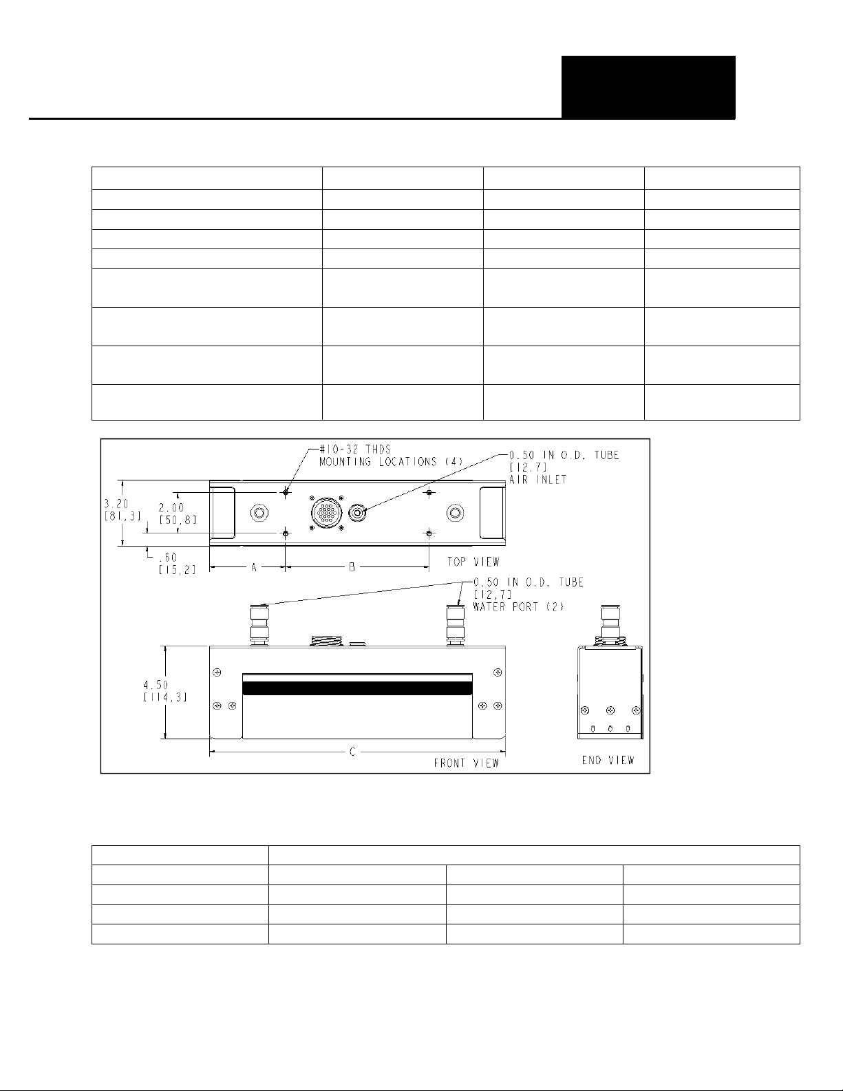
The Model 5209 heater should be mounted to a framework or structure that is designed to
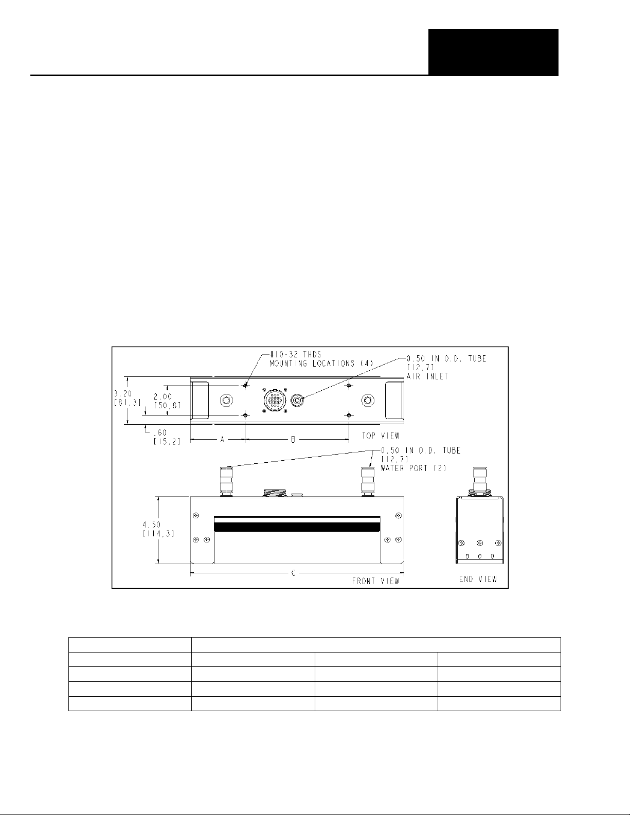
support the weight of the heater and provide stability to the unit. Four #10-32 threaded holes
are located on the top surface of the heater cover and are designed for mounting the heater
(see Figure 3-1).
Note: Vertical burn lamps are recommended when operating the Model 5209 in a vertical
orientation. All PCS/Research Inc. lamps associated with the Model 5209 heater are designed
for vertical operation.
Figure 3-1
5209-05 1.8 (45.7) 5.5 (139.7) 9.10 (231.1)
5209-10 3.73 (94.7) 7.00 (177.8) 14.45 (367.0)
5209-16 3.73 (94.7) 12.63 (320.8) 20.08 (510.0)
Figure 3-1. Model 5209 mounting hole and heater cooling connection locations.
6
Page 11
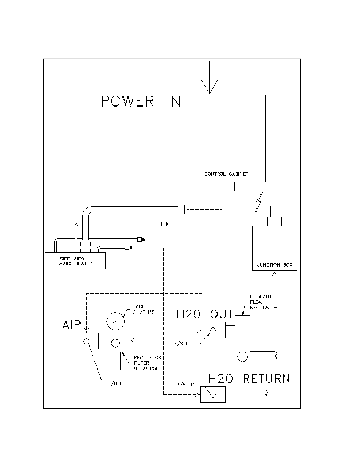
Figure 3-2
7
Page 12
Section 4
4. Operating Instructions
Heater Cooling Connections
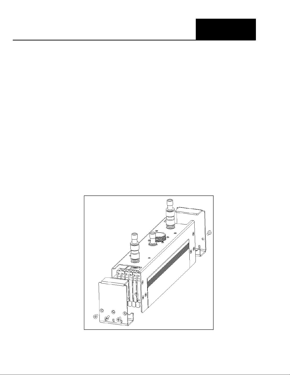
Each Model 5209 is designed with three ‘quick-disconnect’ fittings protruding from the top of
the heater cover. The two fittings located at the outer ends of the heater are the inlet/outlet
cooling water ports. The single fitting located at the center of the heater is the cooling air inlet
port.
All three fittings accept ½-inch outer-diameter flexible nylon tubing. A 30-ft. (9.1 m) length of
tubing and three additional quick-disconnect fittings are shipped with each Model 5209 heater.
The tubing should be cut to specific lengths so that both cooling water and compressed air can
be supplied to the heater. The additional fittings should be used for connecting the tubing
directly to the cooling water and compressed air source.
Once cut to the appropriate lengths, each individual tube length should be inserted into the
appropriate fittings on both the heater and the cooling water and compressed air sources.
Figure 5-2 details a typical installation for the Model 5209 heater.
Note: Fitting plugs are placed into the two water coolant fittings as shipped from the factory. Both of these plugs
must be removed from their respective fittings prior to inserting the flexible tubing. These plugs can either be kept
for future use or discarded. See Figure 4-1 for detail.
Figure 4-1
8
Page 13
Electrical Connections
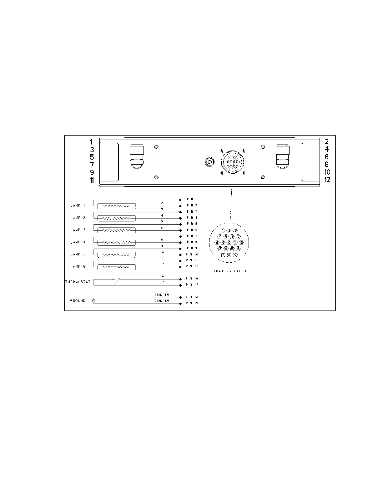
Each of the six T3 lamps of the Model 5209 is electrically wired to intermediate, individual
terminal blocks within the heater. In turn, each terminal block along with the heater safety
thermostat and heater grounding wires are wired to a 19-pin connector mounted to the heater
cover (see Figure 4-2).
Figure 4-2
Each heater is supplied with either a 10- or 20- ft. (3- or 6 m) removable electrical cable that
mates directly to the pinned connector mounted to the heater cover (see Figure 4-3). The
cable length is specified within the heater model number at time of order. Each wire housed
within the cable assembly extends approximately 2-ft. (0.6 m) beyond the end of the cable
conduit. This extra wire length allows the cable to be installed within the optional electrical
junction box or within an appropriately designed power source.
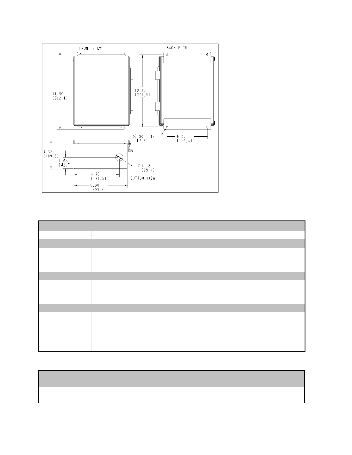
An optional electrical junction box is available and can be ordered along with the Model 5209
heater. The physical dimensions of this junction box are shown in Specifications – Section 6.
9
Page 14
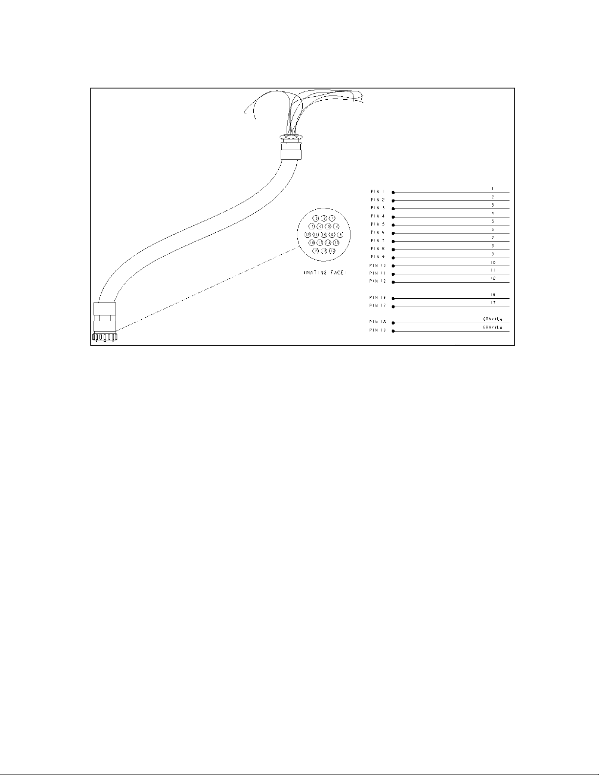
Figure 4-3
As shown in Figure 4-4, the junction box is designed to accept wiring from the removable
heater cable as well as wiring from the electrical power source. Different wiring configurations
are shown so that the heater wiring can be correctly connected within the junction box
corresponding to a particular (supply) line voltage, i.e. since the Model 5209-05, 5209-10 and
5209-16 models use T3 lamps rated for 240-volt operation, one could install the heater wiring
so that either 240-volt single- or three-phase supply power could be used.
Heater Thermostat
As stated above, a heater safety thermostat is mounted to the back of the model 5209 reflector
and wired into the 19-pin connector mounted to the heater cover. Wiring for the thermostat is
also integrated within the removable electrical heater cable.
When wired into an appropriately designed power source (i.e. the Model 915 ControlIR Power
Control System – See Appendix for detail), the normally closed thermostat will open upon
reaching an overheat condition (160°F) resulting in an alarm condition to occur at the power
controller. The thermostat will close once the heater cools down to a safe operating
temperature (approximately 140°F).
An alarm condition signal can be configured within the power control system to alert the user
that the alarm condition exists (i.e. signal light, signal horn, etc.). Additionally, the power
10
Page 15
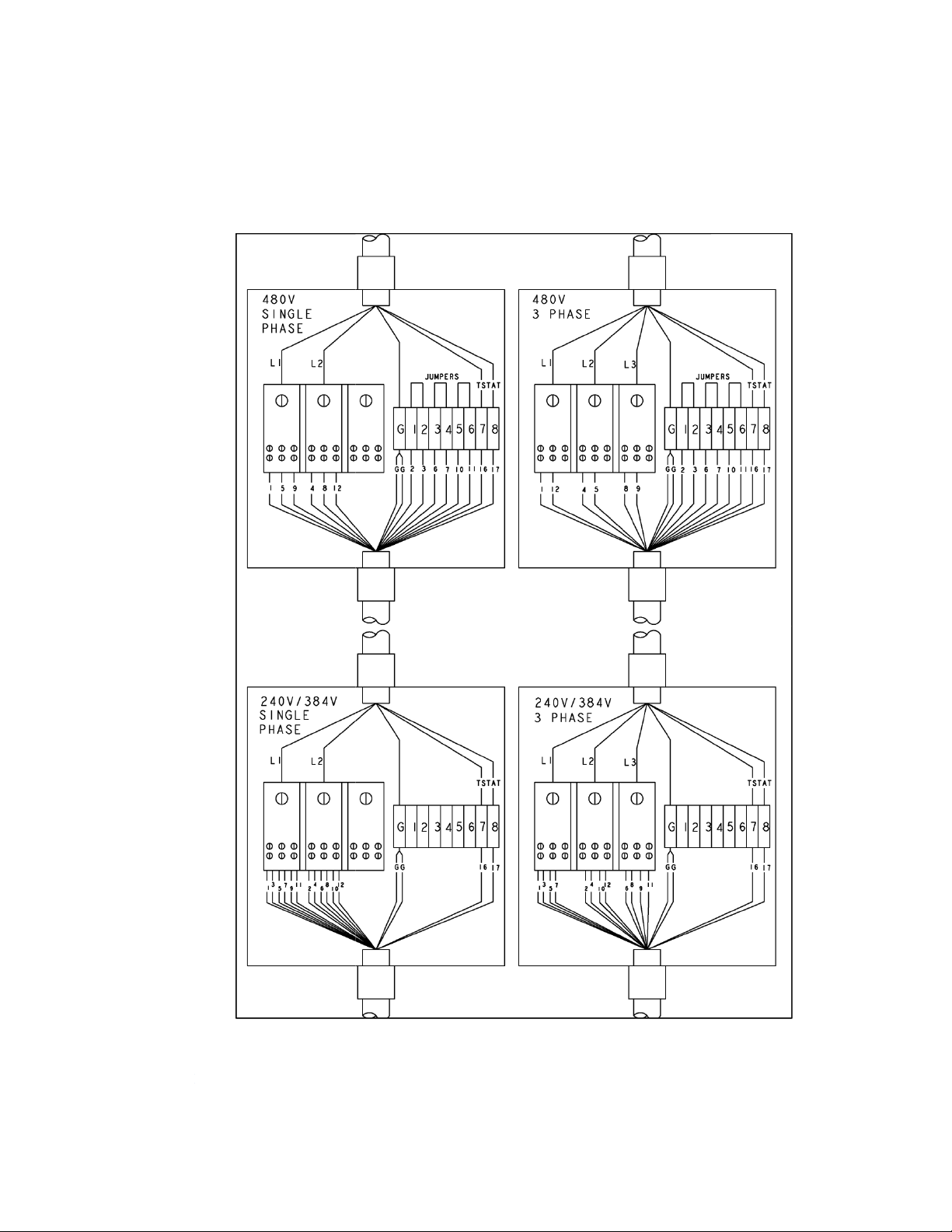
can be configured so that electrical power is removed from the Model 5209 if
the thermostat reaches an overheat condition.
control system
Figure 0-1
11
Page 16
Section 5
5. Maintenance & Troubleshooting
The repair and maintenance of the Model 5209 includes replacement of the T3-style lamps
and quartz wind and cleaning of the reflector.
Lamp Removal, Replacement, Installation
The six T3-style lamps are installed into the Model 5209 heater when shipped from the factory.
The following procedure details the process to replace the lamps in the Model 5209 (reference
Figure 5-1, 5-2, & 5-3):
Note:
• Remove all power from the heater BEFORE attempting to install/replace the lamps.
• Allow a minimum of ½-inch (12 mm) of slack in the lamp lead so that the lead is not taut
when inserted into the lamp terminal block.
• Always take care to handle all lamps by the ceramic end seals and use clean cotton or
latex gloves to prevent contamination of the quartz lamp envelope.
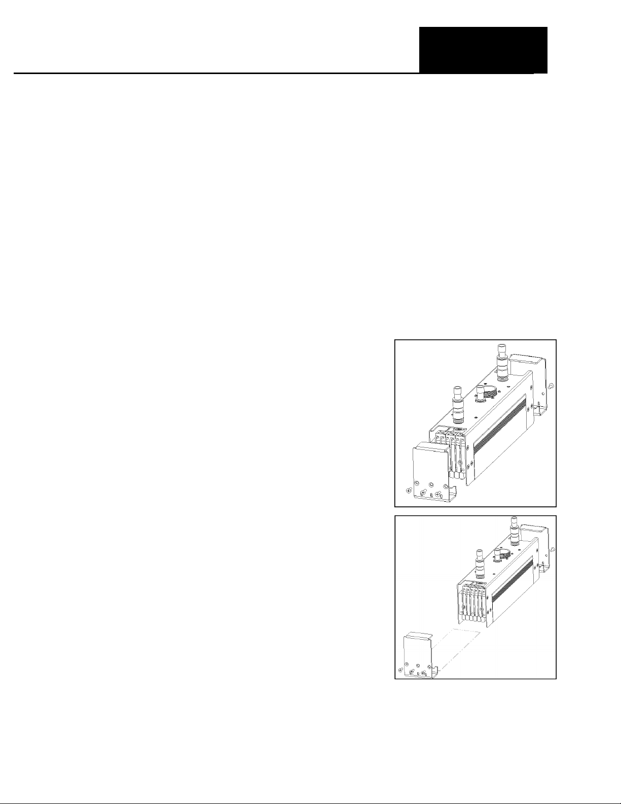
1. Remove End Cover Screws (3 per end cover).
2. Remove End Covers on both ends of the heater.
3. If installed in the heater, remove the quartz
window from the heater by sliding the window out
of the slots machined into the reflector body. Take
this opportunity to clean the window using nonabrasive cleaning solvent and clean, soft cotton
cloth (see Section 6).
Figure 5-1
12
Page 17
4. Loosen (do not remove) the setscrews in the ceramic
terminal blocks on each end of the heater corresponding to
the lead wires of the lamp to be replaced.
5. While holding the lamp, gently pull the lead wires out of the
ceramic terminal blocks and set the old lamp aside for
disposal.
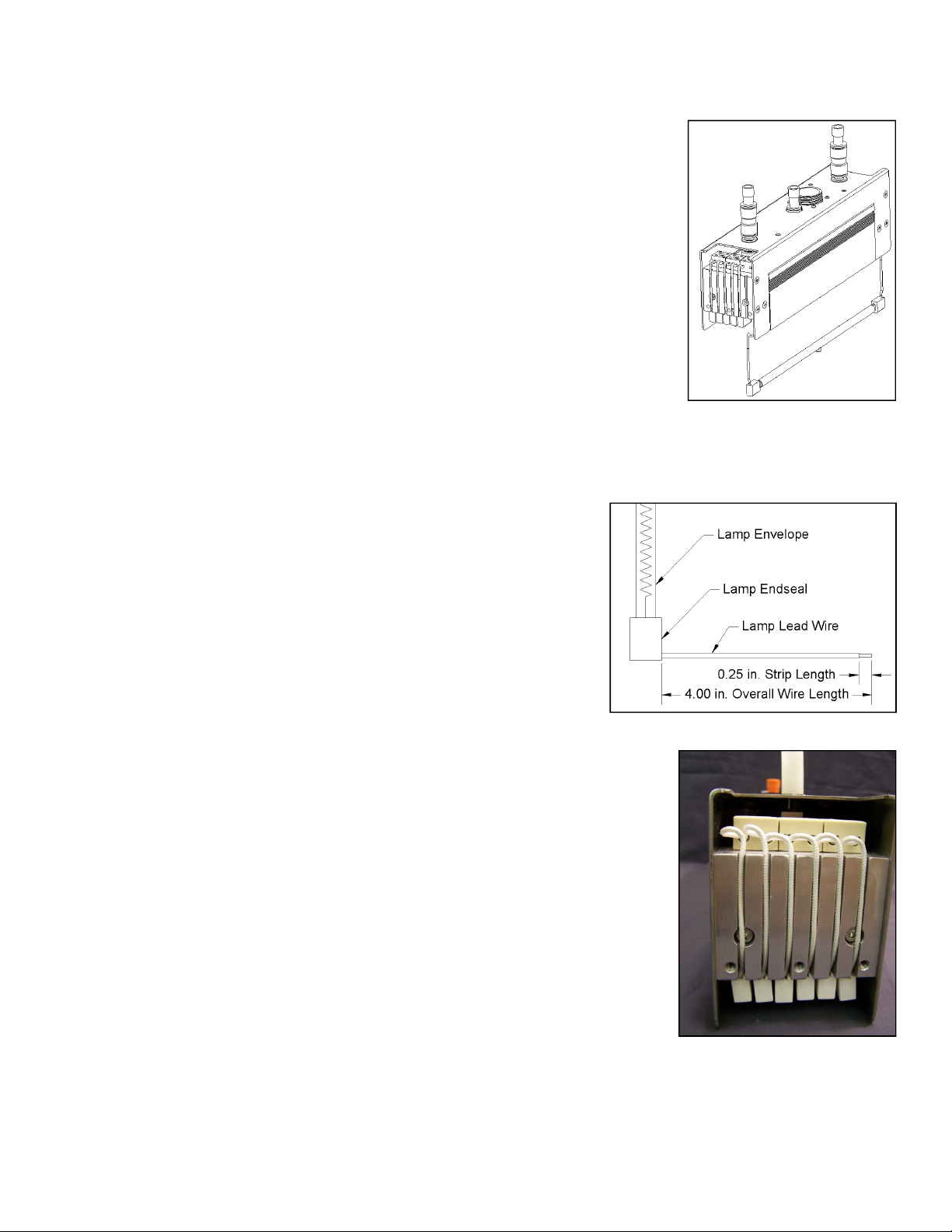
6. Both lead wires of the lamp need to be trimmed prior to
installation into the heater. Figure 5-3 details the proper
lengths to which the lead should be trimmed and stripped.
7. While holding the replacement lamp by the ceramic end
seals, place the lamp into the groove machined into each
lamp bracket plate located on each end of the heater. Orient the lamp so that the gas fill
tip , formed into the quartz tube of the lamp, points out away from the reflector.
8. Insert the bare wire of each insulated lamp lead
into the ceramic terminal block position that
previously held the old lamp. Push each lead wire
into the terminal block far enough so, that when
tightened, the setscrew will hold the lead securely.
9. Tighten the setscrews in each terminal block so the
lead wires are held securely. Note: tighten the
terminal block set screws to a torque of 0.6 feet –
lbs. (0.82 N-m).
10. Arrange the lead wire on each end of the lamp into the
groove machined into each of the aluminum cooling
manifolds located at either end of the heater. Each groove
corresponds to each of the individual lamps of the heater.
11. Form a loop within each lead along its length from the top
of the cooling manifold and the ceramic terminal block. This
loop will act as a strain relief within the lead during normal
operation of the heater.
12. Reinstall the quartz window within the heater by carefully
sliding the window into the grooves machined into the
heater reflector.
13. Reinstall both end covers and secure each to the heater
with the three screws per end cover.
Note: tighten the end cover screws to a torque of 1.7 ft.lbs. (2.3 N-m).
Figure 5-2
Figure 5-3
Figure 5-4
13
Page 18

Quartz Window Cleaning and Replacement
The optional quartz window can be replaced or removed from the Model 5209 for periodic
cleaning. Use the following procedure to remove/reinstall/clean the quartz window.
1. Remove the three end cover screws and the end cover from one end of the
heater.
2. Gently slide the quartz window out of the grooves within the heater reflector.
Take care so that the quartz window does not bind and subsequently chip or
crack as it is removed.
3. If cleaning the window, use a non-abrasive glass cleaner and a clean, dry, lintfree cloth. After cleaning, do not touch the inside surface of the window unless
wearing gloves.
4. Reinsert the edges of the window into the grooves machined into both sides of
the reflector body.
5. Gently push the window into the reflector until it is completely seated against the
end cover mounted to the heater.
6. Reinstall the other end cover and secure with the three end cover screws.
Cleaning the Reflector
A clean reflector provides the greatest radiant efficiency. If the reflector surface becomes
contaminated, it reflects less energy. The energy that is not reflected is absorbed by the
reflector, and removed by the cooling water and air. This energy is lost energy.
The following procedure should be used to clean the Model 5209 reflector:
1. Remove the lamps as described in Section 5
2. Clean the reflector with a mixture of warm water and common household ammonia followed
by a thorough wipe-down using a clean-water-dampened flannel cloth.
3. Depending on the type of contamination present on the reflector, a suitable solvent may be
required to remove the contamination. The solvent must be selected based on this inability
to adversely affect the aluminum reflector.
4. Replace the lamps, quartz window (if so desired), and the heater end covers as outlined in
Section 5 – Lamp Removal/Replacement/Installation.
14
Page 19
Model Number
Dimensions, Inches (mm)
Section 6
6. Dimensions and Specifications
Specifications 5209-05 5209-10 5209-16
Weight, pounds (kg) 7.5 (3.4) 10 (4.5) 12.8 (5.8)
Lamp Type QIH240-1000R12 QIH240-2000R12 QIH384-3200R12
Lighted length, Inches (mm) 5 (127) 11 (280) 16 (406)
Rated Voltage 240 240 384
Total Power Dissipated at
Rated Voltage, kW
Cooling Water Flow, GPM
(1/min.)
Cooling Air Flow, SCFM
(M/P/min.) (see also fig. 3-2)
With a Regenerative blower
CFM (M/P/min) @ 6.2 PSI
4 (0.11) @ 3.0 PSI 4 (0.11) @ 1.0 PSI 4 (0.11) @ 1.0 PSI
6 12 19.2
1.0 (3.8) 1.5 (5.7) 2.25 (8.5)
20 (0.57) 20 (0.57) 20 (0.57)
Figure 6-1
A B C
5209-05 1.8 (45.7) 5.5 (139.7) 9.10 (231.1)
5209-10 3.73 (94.7) 7.00 (177.8) 14.45 (367.0)
5209-16 3.73 (94.7) 12.63 (320.8) 20.08 (510.0)
Note: The height and width dimensions are identical on all three sizes of the Model 5209.
15
Page 20
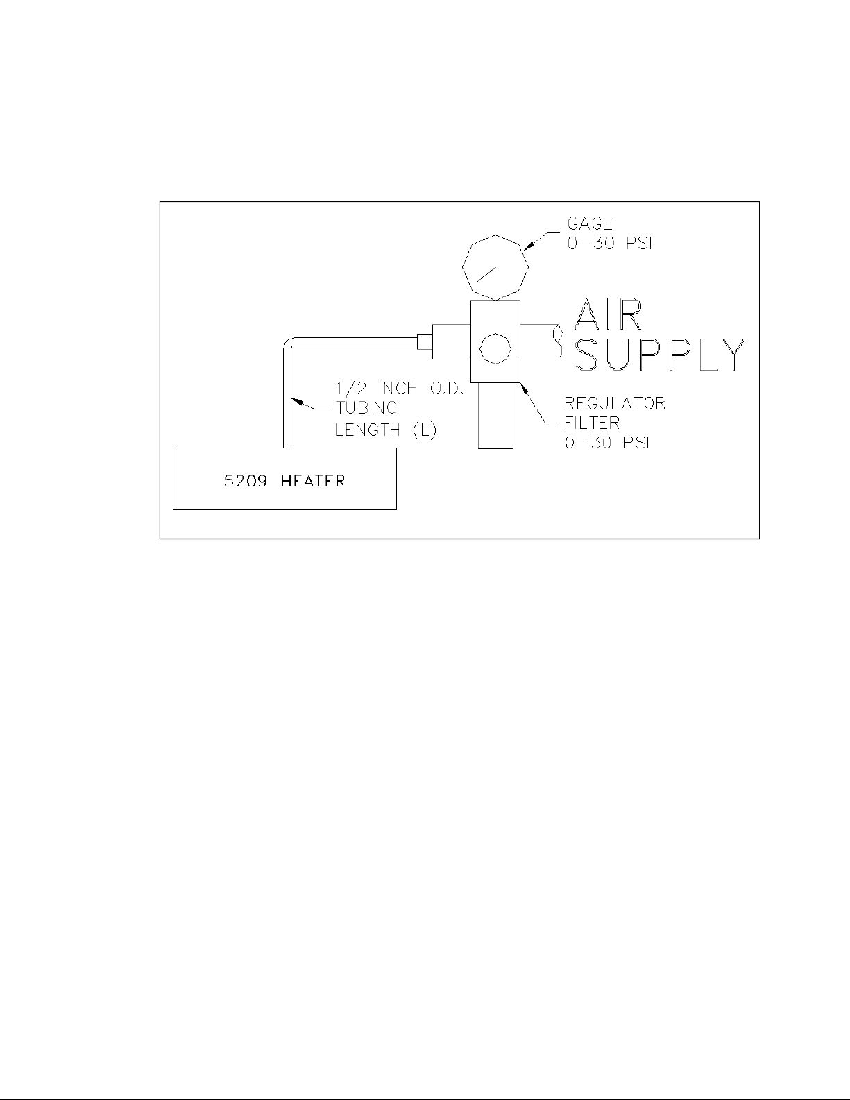
Figure 6-2
16
Page 21
Code
Electrical Cable Length
10 Feet (3 m)
20 Feet (6 m)
None
Code
Optional Equipment
Quartz Window
Electrical Junction Box
(1)
Power Control System with Pyrometer Input
(1)
Power Control System
with Thermocouple Input
(1)
Power Control System with Digital Volt Meter
Figure 6-3
Model Product Description
5209 High Temperature Infrared Heater
Code Lighted Length
05
10
16
10
20
N
W
JB
PC-TCP
PC-TCT
PC-VM
(1) Model 5209 heater supplied with Model 915 ControlIR Power Control Systems. Must specify electrical cable length
(either 10- or 20-feet (3- or 6m) when ordering any of the PC Option choices.
Typical Model
Number:
5 Inches (127 mm)
10 Inches (254 mm)
16 Inches (406 mm)
Model
5209 16 10 W PC-TCT
Lighted
Length
Electrical Cable
Length
Optional
Equipment
17
Page 22

Model
Description
Accessories, Spare & Replacement Parts – Model 5209
106580-003 Quartz Window, 5-inch (127 mm) lighted length heater
106580-001 Quartz Window, 10-inch (254 mm) lighted length heater
106580-002 Quartz Window, 16-inch (406 mm) lighted length heater
103390-002
Quartz, Halogen Infrared Lamp, Ceramic end-seal, 5-inch (127 mm)
lighted length
103390-004
Quartz, Halogen Infrared Lamp, Ceramic end-seal, 10-inch (254 mm)
lighted length
103390-006
Quartz, Halogen Infrared Lamp, Ceramic end-seal, 16-inch (406 mm)
lighted length
106513-001
Electrical Junction Box, accepts Model 5209 Removable Electrical
Cable
106514-001 10-ft. (3 m) Electrical Cable Assembly
106514-002 20-ft. (6 m) Electrical Cable Assembly
106617-001 Cooling Air Regulation Kit
106618-001 Cooling Water Plumbing Hardware Kit
18
Page 23

Item
Part Number
Part Description
A
B
C
A
A
A
A
Section 7
7. Spare & Replacement Parts
Replacement parts for the Model 5209 are listed below. Reference Figure 7-1 when using this list.
1 054979-020 SCREW-PH 4-40X3/8 SST PH
2 054979-042 SCREW-PH 6-32X1/4 SST PH
3 054979-052 SCREW-PH 6-32X5/8 SST PH
4 054979-105 SCREW-PH 10-32X1/4 SST PH
5 054982-001 NUT-KEP 4-40 NC ZINC
6 055020-087 SCREW-FH, 10-32X1/2,SST, PH(100)
7 055296-037 SCREW-SOCKET 10-32 X 1-1/2 SS
8 055298-013 SCREW-SET2-56X1/4 ALNCUP SST
9 070025-015 THERMOSTAT-SURF NC 160F
10
106514-013 Wire Harness, W/Receptical, -- Model 5209-05
10
106514-011 Wire Harness, W/Receptical, -- Model 5209-10
10
106514-012 Wire Harness, W/Receptical, -- Model 5209-16
11 100571-001 TERMINAL BLOCK CERAMIC 2P 10A
12 103390-004 LAMP-QIH240-2000/V CER.END
12
12B 103390-004 LAMP-240V-2000W, 10-inch (254 mm) Lighted Length
12C 103390-006 LAMP-384V-3200W, 16-inch (406 mm) Lighted Length
13 103830-001 FITTING-POLY, 1/8NPT,INSTANT
14 104358-001 FITTING-ELBOW, 3/8NPT
15 104358-002 FITTING-POLY, 1/8NPT-.250OD TUBE, 90 ELBOW
16 104399-001 FITTING-POLY, 3/8NPT, 1/2TUBE, INSTAN
17 105083-001 COUPLING-TUBING, 1/2"
18 106176-001 FITTING-PLUG, 1/2 TUBE
19
19B 106502-002 COVER, 5209-16
19C 106502-003 COVER, 5209-05
20 106503-001 END COVER, 5209-XX
21 106504-001 BRKT, LAMP, POS, 5209-XX
22 106505-002 MANIFOLD, 5209-XX
23 106506-001 FITTING-PLUG, 1/4NPT,BRASS
24
24B 106508-002 REFLECTOR, 5209-16 in
24C 106508-003 REFLECTOR, 5209-5 in
25 103843-001 TUBING-POLY, FLO, 1/4"ODX0.04"WT
26 104431-001 TUBING, 1/2" DIA X 2.5L
27 106511-001 BUSHING-SNAP, .50"ID, .75"DIA PNL
28 106518-001 FITTING-RED, 3/8FPT, 1/8FPT, BRS
29 106519-001 FITTING-NIPPLE, 1/8X1/8, 3/4L, BRS
30
30B 106580-002 WINDOW-QUARTZ, 5209-16 in (OPTIONAL)
30C 106580-003 WINDOW-QUARTZ, 5209-5 in (OPTIONAL)
103390-002 LAMP-240V-1000W, 5-inch (127 mm) Lighted Length
106502-001 COVER, 5209-10
106508-001 REFLECTOR, 5209-10 in
106580-001 WINDOW-QUARTZ, 5209-10 in (OPTIONAL)
19
Page 24
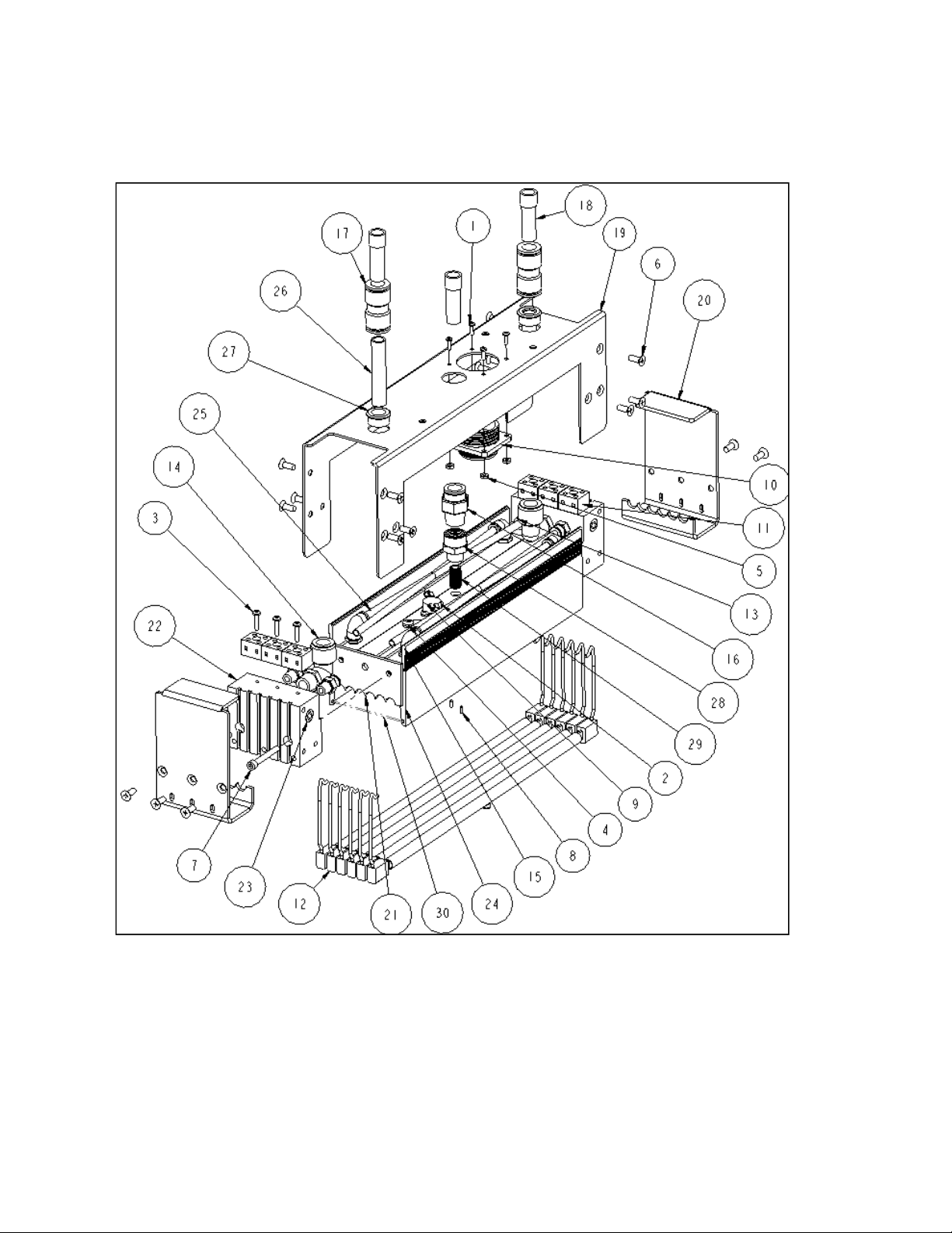
Figure 7-1
20
 Loading...