

Page 1
Control Concepts
Model 1032
Po w er Co ntrol System
Instruction Manu al
(952) 949-9009 Fax (952) 949-9559
Another quality product from:
7128 Shady Oak Road
Eden Prairie, MN 55344 USA
www.researchinc.com
Page 2
CONTROL
CONCEPTS
INC.
INSTRUCTION MANUAL
MODEL 1032
CONTROL
CONCEPTS
7870 PARK DRIVE
CHANHASSEN, MN 55317
(952)-474-6200
1-800-765-2799
FAX (952) 474-6070
Page 3
The model 1032 is a single-phase, phase-angle, SCR
power controller with features of field adjustable current limiting, soft-start and missing cycle detection.
The controller can be ordered to accept command
signals of 0-10Vdc, 0 to 5Vdc, 1-5mA, 4-20mA, or a
potentiometer signal. Models are available for operation at 120, 208, 240, 377, 480 or 575Vac 50/60 hertz.
The controllers can be obtained with current ratings of
10, 20, 30, 40 or 70 Amps.
The model 1032 linearly controls, with respect to the
command signal, the RMS value of the voltage applied
to the load. The controller also has line voltage
compensation, which, for a constant command signal, maintains the load voltage constant, independent
of line or supply voltage variations.
The soft-start and missing cycle detection features
set the load voltage to zero on power interruptions of
one half cycle or more, and then increases the load
voltage to the desired value at a predetermined rate.
This feature, on start up or after power failures,
prevents saturation of load transformers. The feature
also eliminates in-rush currents that can occur, due to
loads with a low cold resistance.
Current limiting allows the user to adjust the maximum current the controller will apply to the load. This
feature is desired when controlling loads such as
silicon carbide, molybdenum disilicide, or other materials in which the resistance changes with temperature and/or time.
Electrical isolation of the circuit card and the heat
sink is achieved by the use of an SCR that electrically
isolates the SCRs from its mounting plate, and which
uses photo couplers to isolate the SCR gate signals.
THEORY OF OPERATION:DESCRIPTION:
The heart of the power controller is the SCR
(Silicon Controlled Rectifier, also sometimes referred to as a thyristor).
The SCR has two states, ON and OFF, and allows
current to flow in only one direction when turned
on. SCRs can remain in the off state even though
the applied potential may be several thousand
volts. In the on state, they can pass several thousand amperes. When a small signal is applied
between the gate and cathode terminals, the SCR
will turn on within 10-100 microseconds. Once
turned on, it will remain on until the current through
it is reduced below a very low value, referred to as
the holding current. Since the SCR conducts in
only one direction, two are placed back to back in
an inverse parallel configuration to control AC
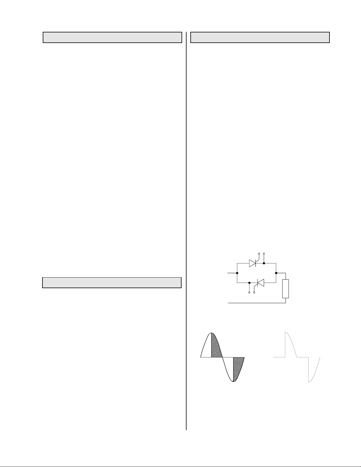
current. (Figure 1A.)
Phase-angle: In phase-angle control, each SCR
of the back-to-back pair is turned on for a variable
portion of the half-cycle that it conducts (Figure 1,
B&C). Power is regulated by advancing or delaying
the point at which the SCR is turned ON within
each half cycle. Light dimmers are an example of
phase-angle control.
Phase-angle control provides a very fine resolution
of power and is used to control fast responding
loads such as tungsten-filament lamps or loads in
which the resistance changes as a function of
temperature. Phase-angle control is required if the
load is transformer-coupled or inductive.
MODEL No. IDENTIFICATION:
MODEL NUMBER: 1032-VV-AA-CS(-ILXX)
L
O
A
D
VV = Rated voltage
12 = 120Vac
24 = 240Vac (For 208 or 220 specify SC208 or
Figure 1A. Simplified diagram of an SCR controller
SC220)
48 = 480Vac (for 377 specify SC38)
57 = 575Vac
AA = Rated current capacity 10, 20, 30, 40 or 70 A
CS = Command Signal; The standard controller accepts
a 0 to 5Vdc, a 0 to 10Vdc, or a potentiometer signal.
If the controller has been supplied as a 4/20mA input, a
-4/20mA designator will be included in the model
number. An appropriate shunt resistor will be added to
the circuit to provide proper scaling. Check with factory
for other mA input ranges.
The term ILXX added to the model number implies that
the current limit will be factory adjusted for the value
specified by XX. When the ILXX term is not included,
the current limit will be factory set at 105% of the rated
Figure 1B. SCR "ON"
time, shown by shaded
area, is varied to apply
the desired load
voltage.
Figure 1C. Voltage
waveform, as applied
to load.
current.
Model 1032 1 of 9 Part No. 5000095-1011-6 6/13/2003
Page 4
INSTALLATION: START UP:
The controller must be mounted on a vertical surface
such that the heat radiating fins are vertical, as
shown in fig. 2 on P.3 & fig. 4 on P.4. The controller
should be located in an environment that will not
exceed 135°F and is free of dust, dirt and moisture.
Figures 6 & 7 on P. 6 show power and control
connections. All wiring must be per local electrical
codes. The supply and load terminals will accept
aluminum wire from #2 to #8 and copper wires from
# 2 to #14.
The control transformer supplied with the controller
provides 24Vac to the circuit. This transformer
must be connected to the same electrical phase
from which the controller and load are connected.
One transformer can be used to operate up to 6
controllers, providing all controllers are connected
to the same phase. (A common installation error is
that of connecting the transformer to a different
phase, or being connected across the SCR module,
rather than from the power supply.
It is recommended that the controller and the load
be protected with fast acting fuses such as the JJN
and JJS, class T, series of fuses manufactured by
the Bussmann Company. See p. 9
Set the command to zero and apply system power.
The load voltage should start at zero and should
increase as the command signal is increased. The
load voltage and current may be measured with any
meter. Because of the non-sinusoidal wave-form
applied by the SCRs, accurate measurements can
only be made with true RMS meters.
ADJUSTMENTS:
Zero:
(Factory set to provide zero load voltage when a
zero command signal is applied) The zero
potentiometer is used to adjust the controller to
provide zero load voltage when the command is
zero.
Span:
(Factory set to provide 100% output with 100%
command) The span determines the load voltage
for a given command input.
Current Limit:
Factory set at 105% of rated current unless ordered
with a specific current limit setting. Counterclockwise rotation decreases the point at which
current limit occurs.
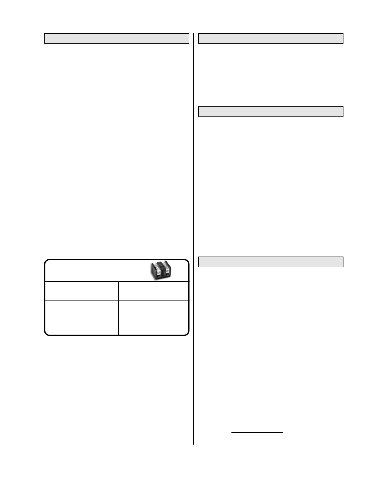
TORQUE TABLE FOR
USD CONNECTORS
Wire Size
Recommended
Torque
10 -14 ga 35 in-lbs
8 ga 40 in-lbs
4 - 6 ga 45 in-lbs
2-3 ga 50 in-lbs
NOTES:
Wiring should be installed per local electrical codes.
24 Volts AC must be supplied to the circuit board
from the same phase being controlled.
The transformer supplied with this controller has a
primary voltage close to or at the voltage which the
controller was designed to control.
The wiring from the transformer to the circuit board
may be in the range of 18 to 24 gauge.
CALIBRATION
The span and zero have been adjusted at the
factory and should require no further adjustments.
If adjustments become necessary, the following
procedures should be used:
(see figure 8 on p. 8 for location of adjustments.)
1. Set the command signal to minimum and adjust
the zero potentiometer until the output is zero.
2. Set the command signal to maximum and adjust
the span potentiometer until the output is at the
desired maximum value.
3. The span and zero adjustments may interact.
It may be necessary to repeat steps 1 and 2.
Note: Loads with variable resistance may cause
the current limiting feature to limit the output of the
controller, which would appear as though the span
is not adjusted properly.
To test for current limiting, rotate the current limit
pot 1 turn counterclockwise. If the load current
decreases, the current limit is controlling the output.
Model 1032 2 of 9 Part No. 5000095-1011-6 6/13/2003
Page 5
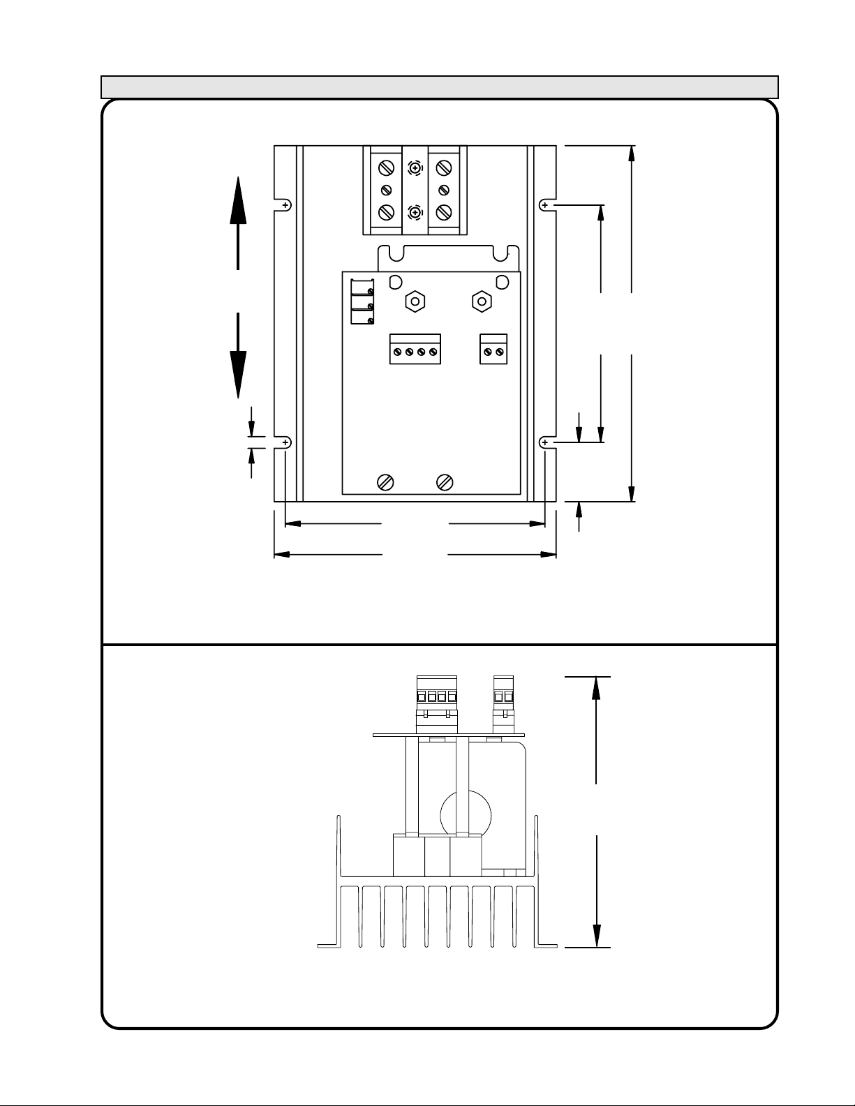
DIMENSIONS: 10 - 40 Amp Frame
UP
0.19
4.375
1.00
4.0
6.0
4.75
Figure 2. Mounting dimensions of 10 to 40 Amp model 1032.
5.50
Figure 3. End view of 10 to 40 Amp model 1032.
Model 1032 3 of 9 Part No. 5000095-1011-6 6/13/2003
Page 6
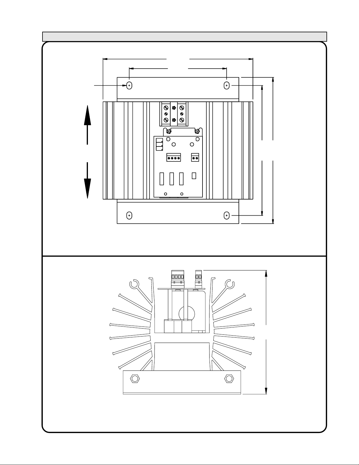
DIMENSIONS: 70 Amp Frame
0.32 wide X
0.45 long (4)
UP
9.25
6.00
8.00
9.00
Figure 4. Mounting dimensions of 70 Amp model 1032.
8.00
Figure 5. End view of 70 amp model 1032.
Model 1032 4 of 9 Part No. 5000095-1011-6 6/13/2003
Page 7
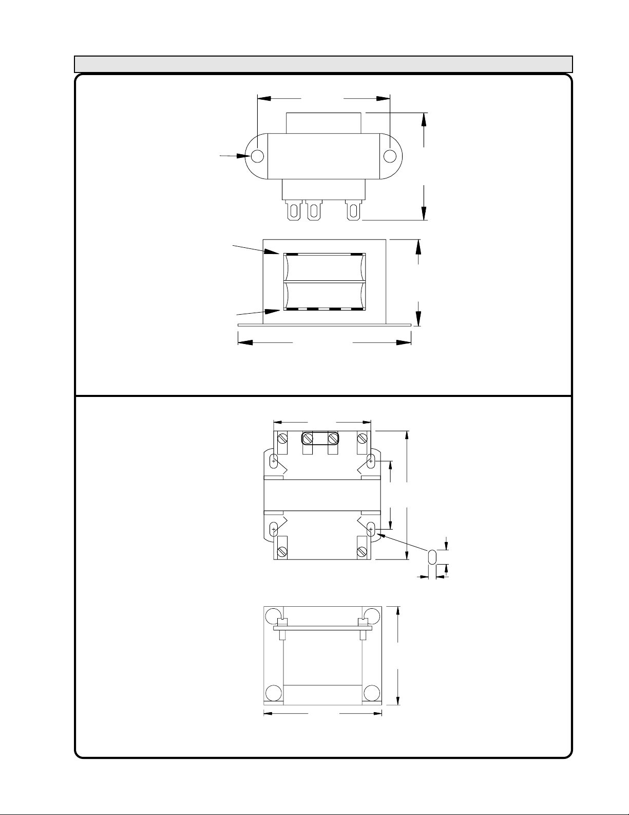
DIMENSIONS: Transformers
0.177 Dia (2)
24 VAC
Secondary
120 or 240
Volt Primary
2.00
1.62
1.19
2.375
120/240 VOLT PRIMARY TRANSFORMER
2.50
480 Volt
Primary
1.75
3.30
24 VAC
Secondary
0.20 (4)
2.50
0.365 (4)
2.50
480 VOLT PRIMARY TRANSFORMER
Model 1032 5 of 9 Part No. 5000095-1011-6 6/13/2003
Page 8
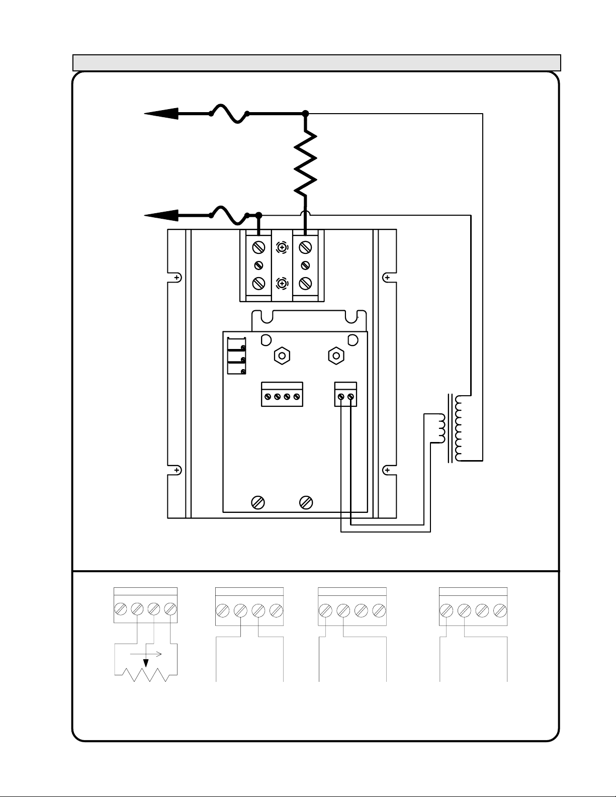
ELECTRICAL CONNECTIONS:
SUPPLY
SUPPLY
FUSING
RECOMMENDED
SEE PAGE 9
COMMAND
CONNECTOR
See Fig. 7.
L
O
A
D
24VAC
PRIMARY
TRANSFORMER
SUPPLIED WITH
CONTROLLER
SEE PAGE 5
Figure 6. Power :Connections
5 CCW W CW
CCW
POT
COMMAND
W
CW
5 CCW W CW 5 CCW W CW 5 CCW W CW
NEG
0-10Vdc
COMMAND
POS
POS
0-5Vdc
COMMAND
NEG
POS
4/20 mAdc
COMMAND
NEG
Figure 7. Signal Connections
Model 1032 6 of 9 Part No. 5000095-1011-6 6/13/2003
Page 9
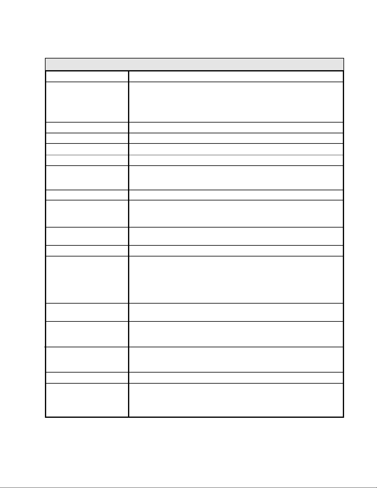
SPECIFICATIONS
Control Mode
Command Signal
Control Range
Linearity
Zero and Span Adj.
Current Limit Adj.
Isolation
Cooling
Mounting
Line voltage
Load Current
Diagnostic Indicators
Single-phase; Phase-angle; RMS value of the voltage applied to the load
Signal Impedance
0-5Vdc 100K
0-10Vdc 200K
1 to 20 K Pot. 200K
4-20mA 300 ohms
6 to 97% of line voltage, typical.
RMS load voltage is linear within 2% of span of the command signal.
User adjustable over a range of 20% of span
User adjustable over a range from 20% to 110% of rated current
Dielectric strength input/line & load voltage/heatsink: 2500 V(RMS)
Insulation resistance input/line & load voltage/heatsink: 1010 ohms.
Maximum capacitance input to output: 8 pf
Convection
Must be mounted on vertical surface with fins vertical. Units may be
mounted adjacent to each other. Heat sink is electrically isolated from
circuit and power.
120, 240, 480 & 575Vac +10%,-20% 50/60 Hertz
Consult factory for other voltages.
10, 20, 30, 40 & 70 Amps A.C. 50/60 Hertz.
The intensity of the 'SSR DRIVE' LED varies proportionally to the
Voltage applied to the load.
The intensity of the 'LOAD CURRENT' LED varies as a function of the
load current.
These LED's provide a quick and safe means to check controller
operation
Physical
Environment
dv/dt & Transient
Voltage Protection
Heat dissipation
Recommended Fusing
Model 1032 7 of 9 Part No. 5000095-1011-6 6/13/2003
Weight: 10 thru 40 amps: 5 lbs. max., 70 amps: 9 lbs. max.
Dimensions: See installation drawings, pages 3 & 4.
Operating: 0 to 55oC (32 to 131oF)
Storage: -40 to 80oC (-40 to 176oF)
Humidity: 0 to 95% Non-condensing
200 volts/usec minimum
A dv/dt snubber and a metal oxide varistor (MOV) are provided to
protect against high frequency transients (dv/dt) and voltage spikes.
1.5 watt per amp of controlled current
Special semiconductor fuses are not required. It is recommended that
the controller and load be protected with fast acting class "T" fuses
such as Bussmann type JJS or JJN fuses. Control Concepts
maintains an inventory of fuses and fuse holders for your convenience.
Page 10
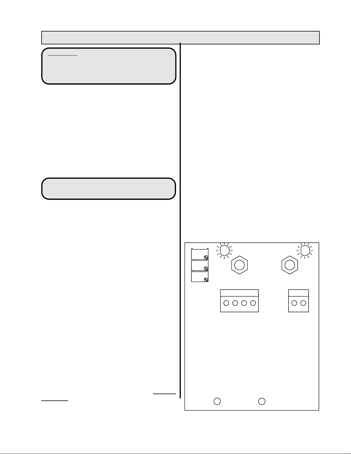
TROUBLE SHOOTING:
CAUTION: High voltage exists on the supply
and load terminals of this controller, and
may exist on other equipment located near
the controller. Use extreme caution to avoid
electrical shock.
Two LED's on the circuit board may be used to aid
in determining problems with the controller.
The 'SSR DRIVE' LED varies in intensity proportional
to the drive signal to the Solid State Relay and is
proportional to the load voltage.
The 'LOAD CURRENT' LED varies in intensity
proportional to the current through the load. If the
load current reaches the current limit setting, the
intensity of the 'LOAD CURRENT' LED will no
longer increase and the load current will remain
fixed.
THE FOLLOWING ARE SYMPTOMS
AND POSSIBLE SOLUTIONS:
NO LOAD POWER:
The 'LOAD CURRENT' LED is not on, the
intensity of the 'SCR DRIVE' LED can be varied:
Determine that the load is wired correctly to the
controller. Determine that all fuses are OK. If the
voltage across the SCR module is equal to the line
voltage, the SCR module has probably failed.
If a replacement SCR module is ordered, specify
the voltage, current rating and serial number of the
failed unit.
MAXIMUM LOAD VOLTAGE CANNOT
BE REACHED:
Determine that the primary of the circuit transformer
is connected across the same supply as the
controller and load.
This problem could be caused by the primary being
connected across the load and line connection at
the controller, or across a different phase than the
controller and load. (Fig. 6 on P. 6.)
The current limit feature may prevent maximum line
voltage from being applied to the load. To determine
if the current limit feature is preventing full voltage
from being applied to the load, rotate the
potentiometer labeled "LIMIT" 1 turn counterclockwise. If the load voltage decreases, the load
current is being limited.
LOAD POWER IS MAXIMUM AND
CANNOT BE REDUCED:
'SCR DRIVE' LED is on:
Determine that the command signal is zero. To
do this, remove the command signal connector. If
the LED remains on, the circuit card has likely
failed.
'SCR DRIVE' LED is off:
Remove the 24Vac power connector. If the load still
has power, the SSR module has probably failed.
To determine if the SSR module is shorted, remove
the line and load connections and measure the
resistance across the line and load terminals of the
controller.If the resistance is less than 10,000
ohms, the SCR module has probably failed.
If a replacement SCR module is ordered, specify
the voltage, current rating and serial number of the
controller.
Load voltage snaps on:
Determine that the primary of the circuit transformer
is connected across the same phase as the
controller and load. (See figure 6 on page 6.)
'LOAD
CURRENT'
LED
ZERO
SPAN
LIMIT
5 CCW W CW
COMMAND
SIGNAL
CONNECTOR
'SSR
DRIVE'
LED
24 Vac
CONNECTOR
Figure 8. 1032 Board Layout.
Model 1032 8 of 9 Part No. 5000095-1011-6 6/13/2003
Page 11
ORDERING PARTS:
REFERENCE DRAWINGS:
Firing Circuit, Specify: 1032-FC
(Include the command range when ordering).
See below for numbers for spare SCR modules
and recommended fuses. If a replacement SCR
module is ordered, specify the voltage, current
rating and serial number of the failed unit.
REPLACEMENT PARTS:
RECOMMENDED
REPLACEMENT SCR:
ASSEMBLY
MODEL:
1032-12-10
1032-12-20
1032-12-30
1032-12-40
1032-12-70
1032-24-10
1032-24-20
1032-24-30
1032-24-40
1032-24-70
PART No. *
1652-12-10
1652-12-20
1652-12-30
1652-12-40
1652-12-70
1652-24-10
1652-24-20
1652-24-30
1652-24-40
1652-24-70
CCI PART # BUSSMAN #
42110-0460-315
42110-0460-325
42110-0460-335
42110-0460-350
42110-0460-390
42110-0460-315
42110-0460-325
42110-0460-335
42110-0460-350
42110-0460-390
Schematic D1000532A1
Transformer Inst. Dwg. Page 5
RECOMMENDED FUSES (typical)
(Alternative fuse size is 125% of max. load current)
CCI
FUSEKIT **
JJS-15
JJS-25
JJS-35
JJS-50
JJS-90
JJS-15
JJS-25
JJS-35
JJS-50
JJS-90
FK\62T15
FK\62T25
FK\62T35
FK\62T50
FK\62T90
FK\62T15
FK\62T25
FK\62T35
FK\62T50
FK\62T90
1032-48-10
1032-48-20
1032-48-30
1032-48-40
1032-48-70
* The assembly includes the SCR relay, a thermal conductive pad, an MOV and an instruction sheet.
** The fuse kit includes two fuses of appropriate rating for the frame size, and a fuseblock.
Control concepts recommends that fuses be rated at 120 to 125% of maximum load current.
1652-48-10
1652-48-20
1652-48-30
1652-48-40
1652-48-70
42110-0460-315
42110-0460-325
42110-0460-335
42110-0460-350
42110-0460-390
JJS-15
JJS-25
JJS-35
JJS-50
JJS-90
FK\62T15
FK\62T25
FK\62T35
FK\62T50
FK\62T90
MANUFACTURED BY:
CONTROL
CONCEPTS
7870 PARK DRIVE
CHANHASSEN, MN 55317 U.S.A.
(952)-474-6200
1-800-765-2799
FAX (952) 474-6070
www.ccipower.com
Model 1032 9 of 9 Part No. 5000095-1011-6 6/13/2003
 Loading...