


ViewPowerMini
User’s Manual
Management Software for Uninterruptible Power Supply Systems
Table of Contents
1. |
ViewPowerMini Overview.................................................................................. |
2 |
|||
|
1.1. |
Introduction.............................................................................................................................. |
2 |
||
|
1.2. |
Structure..................................................................................................................................... |
2 |
||
|
1.3. |
Features...................................................................................................................................... |
3 |
||
2. |
ViewPowerMini Install and Uninstall .......................................................... |
3 |
|||
|
2.1. |
System Requirement........................................................................................................... |
3 |
||
|
2.2. |
Software Install...................................................................................................................... |
4 |
||
|
2.3. |
Software Uninstall................................................................................................................ |
9 |
||
3. |
Tray Application...................................................................................................... |
9 |
|||
|
3.1. |
Start Monitor............................................................................................................................ |
9 |
||
|
3.2. Icon and Software status............................................................................................... |
10 |
|||
|
3.3. |
Configuration......................................................................................................................... |
10 |
||
|
3.3.1. |
SNMP Manager............................................................................................................. |
10 |
||
|
3.3.1.1. |
SNMP Device List .................................................................................................... |
11 |
||
|
3.3.1.2. |
Function Menu .......................................................................................................... |
16 |
||
|
3.3.2. |
Software Upgrades.................................................................................................... |
23 |
||
|
3.3.3. |
Configuration Saved.................................................................................................. |
24 |
||
|
3.4. |
Software Update.................................................................................................................. |
24 |
||
|
3.5. |
Open Monitor.......................................................................................................................... |
25 |
||
|
3.6. |
Message Board...................................................................................................................... |
25 |
||
|
3.7. |
Exit |
|
............................................................................................................................................... |
26 |
4. |
ViewPowerMini .......................................................................GUI Interface |
26 |
|||
|
4.1. |
UPS .....................................................................................................................Navigation |
27 |
||
|
4.1.1. |
Monitored ..................................................................................UPS Information |
27 |
||
|
4.1.2. UPS ..........................................................................Remote Control & Monitor |
28 |
|||
5. |
ViewPowerMini .....................................................................Function Menu |
30 |
|||
|
5.1. |
ViewPowerMini .....................................................................................Configuration |
30 |
||
|
5.1.1. |
Password .........................................................................................Configuration |
30 |
||
|
5.1.2. |
SMS ......................................................................................................Configuration |
31 |
||
|
5.1.3. |
Email .................................................................................................Configuration |
33 |
||
|
5.1.4. |
Event ...................................................................................Action Configuration |
34 |
||
|
5.1.5. Wake .................................................................................................................on LAN |
35 |
|||
|
5.1.6. Com.Port .........................................................................Plug And Play Setting |
36 |
|||
|
5.1.7. |
Log .....................................................................................................................Setting |
37 |
||
|
5.1.8. |
ModBus ........................................................................Communication Setting |
38 |
||
|
5.1.9. |
EMD ................................................................................................................Manager |
39 |
||
|
5.2. |
UPS .............................................................................................................................Setting |
42 |
||
|
5.2.1. |
Local ...........................................................................................................Shutdown |
42 |
||
|
5.2.2. |
Remote ......................................................................................................Shutdown |
44 |
||
|
5.2.3. |
Parameter ......................................................................................................Setting |
46 |
||
|
5.2.4. |
Purchasing ..........................................................................................Information |
48 |
||
|
5.3. |
Control....................................................................................................................................... |
48 |
||
|
5.3.1. |
Realtime ........................................................................................................Control |
49 |
||
|
5.3.2. |
Scheduled .......................................................................................................On/Off |
50 |
||
1
5.3.3. |
Scheduled Battery SelfTest |
.................................................................................51 |
|
5.4. |
View............................................................................................................................................. |
52 |
|
5.4.1. |
Status................................................................................................................................. |
52 |
|
5.4.2. |
History............................................................................................................................... |
55 |
|
5.5. |
Format........................................................................................................................................ |
61 |
|
5.6. |
Language.................................................................................................................................. |
61 |
|
5.7. |
Help.............................................................................................................................................. |
62 |
|
Appendix A: Glossary...................................................................................................... |
63 |
||
1. ViewPowerMini Overview
1.1.Introduction
ViewPowerMini is UPS management software which is perfect for home users and enterprises; it can monitor multiple devices via USB and Serial port and it can monitor and manage from one to multiple UPSs in a networked environment including LAN, INTERNET and RS485based networks.at the same time. The major functions of ViewPowerMini monitoring software include data log for device, power generation statistics, alarm messages, fault messages, and parameter setting for devices; It can not only prevent data loss from power outage and safely shutdown systems, but also store programming data and scheduled shutdown UPSs
1.2.Structure
ViewPowerMini includes ViewPowerMini service,GUI (user interface) and ViewPowerMini icon.
ViewPowerMini service is the core of ViewPowerMini software. It’s a system program running in the back end. It will communicate with UPS, record event, notify users with events, and execute command according to users’ request.
GUI is operated in Browser and communicated with backend program. Users can monitor UPSs for realtime status, information and modify UPS setting parameters via GUI.
ViewPowerMini icon is managing tool for ViewPowerMini software. When ViewPowerMini is activated, there is an orange plug icon located in taskbar. It also will display popup
2
dialog for current UPS status.
NOTE: Tray icon only exists under Windows OS.
1.3.Features
•Realtime dynamic graphs of UPS data (voltage, frequency, load level, battery capacity)
•Safely OS shutdown and protection from data loss during power failure
•Warning notifications via audible alarm, popup screen, broadcast, mobile messenger, and email
•Scheduled UPS on/off, battery test, programmable outlet control, and audible alarm control
•Password security protection
2.ViewPowerMini Install and Uninstall
2.1.System Requirement
•512 MB physical memory at least (1 GB is recommended)
•1 GB hard disk space at least
•Administrator authority is required
•More than 16bit colors and 800 x 600 or above resolution display is recommended
•An available communication port (RS232 serial port or USB port) is needed
•Platforms supported by software are listed below:
ØWindows 2000/XP/2003/Vista/2008/2012 (32bit & x64bit)
ØWindows 7 / 8 (32bit & x64bit)
ØLinux RedHat 8, 9
ØLinux RedHat Enterprise AS3, AS5, AS6 (32bit)
ØLinux RedHat Enterprise AS6 (64bit)
ØLinux SUSE 10 (32bit & 64bit)
3

ØLinux Cent OS 5.4 (32bit)
ØLinux Ubuntu 8.X, 9.X, 10.X (32bit)
ØLinux Fedora 5
ØLinux OpenSUSE 11.2 (32bit & 64bit)
ØLinux Debian 5.x, 6.x (32bit)
ØLinux Debian 6.x (64bit)
ØMac OS 10.6 / 10.7 / 10.8 (x64bit)
2.2.Software Install
Step 1 After clicking install, it will display the installation in process. Refer to the diagram 23.
Diagram 23
Step 2 Choose wanted language and click “OK” as diagram 24.
4
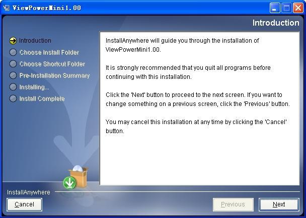
Diagram 24
Step 3 Click “Next” to proceed to the next screen as Diagram 25.
Diagram 25
Step 4 Click “Choose” button to change the default folder. After choosing the installed folder, click “Next” button. Refer to the following diagram 26.
5
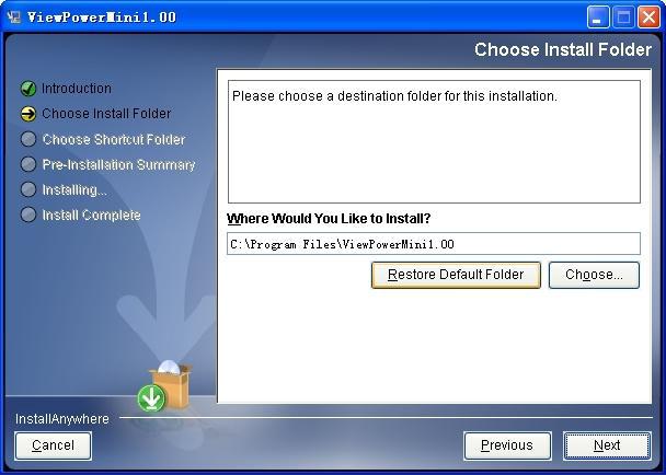
Diagram 26
Step 5 Choose the shortcut folder and click “Next” button. Refer to the following
diagram 27.
6
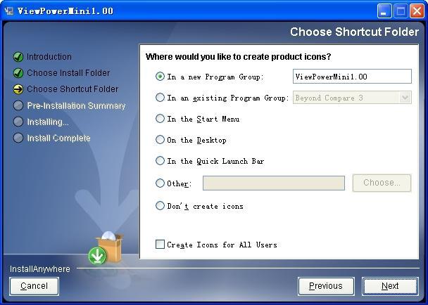
Diagram 27
Step 6 It will display the software summary before installation. Click “Install” button to
start the installation and refer to Diagram 28.
7
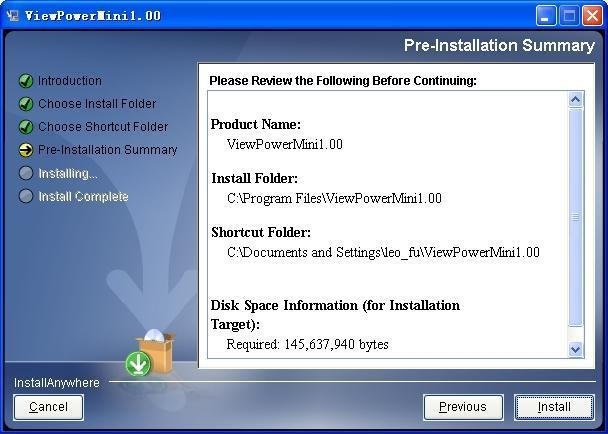
Diagram 28
Step 7 Click “Done” button to confirm the installation completely.
Refer to Diagram 29.
8

Diagram 29
Note: Please uninstall the previous version before install the new version software. If detecting installed ViewPowerMini during installation, it will remind users to
2.3.Software Uninstall
Note: Before uninstall software, you must stop all software programs first and then log in as “Administrator”! Otherwise it can't be uninstalled completely.
Please choose Start >> All Programs >> ViewPowerMini >> Uninstall. Then follow the onscreen instruction to uninstall the software.
3. Tray Application
3.1.Start Monitor
The Installer will leave a shortcut icon on your desktop. Simply click the shortcut. Then it will start the software and display an orange plug icon located in taskbar. To launch the GUI, double click the plug icon or choose “Open Monitor” by clicking right button of the
9
mouse. Refer to below diagram.
Or, use the Start Menu method; Start >> All Programs >> ViewPowerMini >>
ViewPowerMini
Shortcut icon 
 ViewPowerMini icon
3.2.Icon and Software status
•Monitoring application is not activated successfully: 
•Monitoring application is activated as service mode: 
•Monitoring application is activated as application mode: 
3.3.Configuration
3.3.1. SNMP Manager
SNMP Manager is a plugin utility for ViewPowerMini to search and operate all SNMP devices in the LAN.
Click the “SNMP Manager” to access SNMP management tool.
It has four sections as marked in the illustration below:
10

Diagram 31
A.Function menu offers toolset for setting SNMP devices.
B.SNMP device list can list down all SNMP devices with IP address.
C.Configuration area includes Basic info, IP settings, online upgrade, system management, and static trap address.
D.Output window displays all messages for operations
3.3.1.1. SNMP Device List
The default value in window list would be current PC IP address. For example, if IP address of current PC is “192.168.102.10”, it will display “192.168.102” in list when first enabling SNMP Manager.
Scan
You may enter specific IP address and then click “Scan” button to search.
Add
Click “Add” button and it will pop up a window to ask for entering specific IP address. Then, click “Apply” button to add IP address (Subnet). Refer to Diagram 32.
11

Diagram 32
Delete
You may select IP address from the list and remove it by clicking “Del” button.
SNMP Status
It will display SNNP status, 0 or 1, after selecting IP from the IP list. If there is program inside of selected SNMP card, the status becomes 1. If not, it will display 0. If no IP address is selected, it will display ““ as default. Refer to Diagram 33.
12
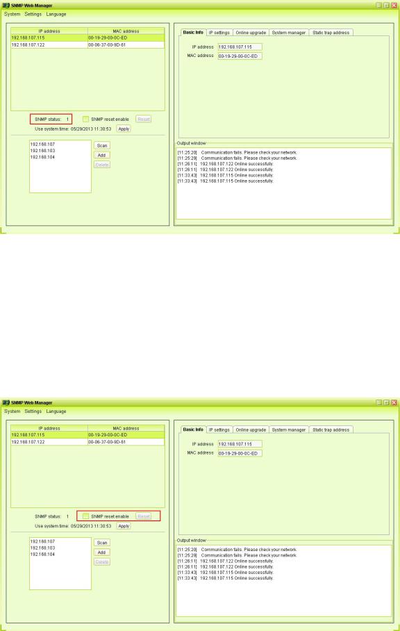
Diagram 33
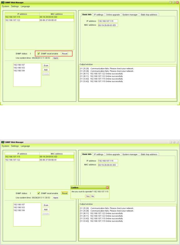
Reset
If it is required to restart the IP addresses of devices, please select the checkbox of "SNMP reset enable" and click "Reset" button. Then, if login is confirmed, you can restart the device. Steps are as follows:
Step1: Select IP address needed to restart IP from the list. Then, "SNMP reset enable" will become available to select. Refer to Diagram 34.
Diagram 34
13
Step2: Click checkbox of "SNMP reset enable". Then, "Reset" button will become available to click. Refer to Diagram 35.
Diagram 35
Step3: Click "Reset" button and it will pop up a message to confirm this operation. Refer to Diagram 36.
Diagram 36
Step4: If "Yes" is selected, it’s requested to log in first. If "No" is selected, it will stop this
operation. Refer to Diagram 37.
14

Diagram 37
Step5: Enter the correct password and click "Login" button. The target device will be
restarted.
NOTE: If changing the MAC address of current device before reboot and the current device is applying DHCP (Automatically obtain IP address) method, you need to manually click "Scan" button to scan.
Use system time
If “Use system time” is selected, the SNMP card will apply PC system time. Refer to Diagram 38.
15
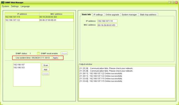
Diagram 38
3.3.1.2. Function Menu
3.3.1.2.1. System
3.3.1.2.1.1. Login
It’s necessary to verify ID to remote access SNMP devices. The default password is “12345678”.
Step 1: Select System >> Login
Step 2: Enter default password and then click “Login” button. Or click “Cancel” to cancel login. Refer to Diagram 39.
16
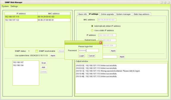
Diagram 39
Logout
Clear all currently saved passwords.
Quit
Select “Quick” to exit SNMP Manager.
3.3.1.2.2. Settings
Basic Info
User can manually enter basic information of SNMP cards such as UPS name, Address, and Note for verification. Refer to Diagram 310.
17

Diagram 310
IP Setting
Diagram 311
Part A: There are two methods to obtain IP address. Select IP address from IP list. It will display MAC address of device in the output window. Refer to section A in Diagram 311.
•Automatically obtain IP address (DHCP)
It will allow system to automatically obtain IP addresses. If there is no this kind of
18
service provided in LAN, the default IP will display as “192.168.102.230”, Net mask as “255.255.255.0” and default gateway as “0.0.0.0”. Simply click “Apply” button to apply this change.
•Use a static IP address
It will allow users to enter static IP address for SNMP devices. When entering IP address, Subnet mask, and gateway address, simply click “Apply” button to apply
this change.
Part B: Enter the DNS and click “Apply” button. Refer to section B in Diagram 312.
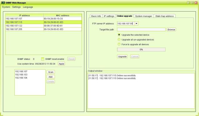
Online upgrade
Diagram 312
There are three methods for online upgrade:
•Upgrade the selected devices: It will upgrade all SNMP devices listed in the IP list.
•Upgrade all unupgraded devices: It will only upgrade SNMP devices which are not using the same version as current SNMP device is.
•Force to upgrade all devices: No matter what kinds of version are used for SNMP devices listed in the IP list, it will upgrade to the latest version for all SNMP devices.
Refer to Diagram 312.
Step1: select the FTP server IP address. Refer to Diagram 46.
NOTE: If applying upgrade for Modbus Web Server in LAN, FTP server IP address will be
19
 Loading...