


Line-interactive UPS
PowerWalker VI 1200-3000 RLE
User Manual
IMPORTANT SAFETY INSTRUCTIONS
(SAVE THESE INSTRUCTIONS)
This manual contains important safety instructions. Please read and follow all instructions carefully during installation and operation of the unit. Read this manual thoroughly before attempting to unpack, install, or operate your UPS.
CAUTION! To prevent the risk of fire or electric shock, install in a temperature and humidity controlled indoor area free of conductive contaminants. (See the specifications for the acceptable temperature and humidity range.)
CAUTION! To reduce the risk of overheating the UPS, do not cover the UPS' cooling vents and avoid exposing the unit to direct sunlight or installing the unit near heat emitting appliances such as space heaters or furnaces.
CAUTION! Do not attach non-computer-related items, such as medical equipment, life-support equipment, microwave ovens, or vacuum cleaners to UPS. CAUTION! Do not plug the UPS input into its own output.
CAUTION! Do not allow liquids or any foreign object to enter the UPS. Do not place beverages or any other liquid-containing vessels on or near the unit. CAUTION! In the event of an emergency, press the OFF button and disconnect the power cord from the AC power supply to properly disable the UPS. CAUTION! Do not attach a power strip or surge suppressor to the UPS.
CAUTION! Unplug the UPS prior to cleaning and do not use liquid or spray detergent.
INSTALLING YOUR UPS SYSTEM
UNPACKING
The box should contain the following:
(1) UPS Unit x 1; (2) User Manual1; (3) USB Cable x 1; (4) RS232 Cable x 1;
HOW TO DETERMINE THE POWER REQUIREMENTS OF YOUR EQUIPMENT
1.Ensure that the equipment plugged into the battery power-supplied outlets does not exceed the UPS unit’s rated capacity. If rated unit capacities are exceeded, an overload condition may occur and cause the UPS unit to shut down or the fuse blow.
2.There are many factors that can affect the amount of power that your computer system will require. For optimal system performance keep the load below 80% of the unit’s rated capacity.
HARDWARE INSTALLATION GUIDE
1.Your new UPS may be used immediately upon receipt. However, recharging the battery for at least 8 hours is recommended to ensure that the battery's maximum charge capacity is achieved. Charge loss may occur during shipping and storage. To recharge the battery, simply leave the unit plugged into an AC outlet. The unit will charge in both the on and off position.
2.With the UPS unit off and unplugged, connect the computer, monitor, and any externally powered data storage device.
3.Plug the UPS into a 2 pole, 3 wire grounded receptacle (wall outlet). Make sure the wall branch outlet is protected by a fuse or circuit breaker and does not service equipment with large electrical demands.
4.Depress the power switch to turn the unit on. The LCD indicator light will illuminate and the unit will "beep".
5.To maintain optimal battery charge, leave the UPS plugged into an AC outlet at all times.
6.To store your UPS for an extended period, cover it and store with the battery fully charged. Recharge the battery every three months to ensure battery life.
ROUTINE MAINTENANCE AND STORAGE
ROUTINE MAINTENANCE
1.Use dry soft clothes to clean the front panel and plastic parts. Do not use any detergent that contains alcoholic ingredient.
2.The expected lifetime of the battery is around 3 years. Improper operation and harsh environment will reduce the actual lifetime.
3.Unplug the UPS from power inlet if the UPS will not operate for long period of time.
STORAGE
1.First turn off your UPS and disconnect its power cord from the wall outlet. Disconnect all cables connected the UPS to avoid battery drain.
2.The UPS should be stored in a cool dry location.
3.Make sure the battery is fully charged before the UPS is stored.
4.For extended storage in moderate climates, the battery should be charged for 12 hours every 3 months by plugging the power cord into the wall receptacle and turning on the main switch. Repeat it every 2 months in high temperature locations.
|
BASIC OPERATION |
FRONT AND TOP PANEL DESCRIPTION |
|
PowerWalker VI 1200/ 2200 RLE |
Front View |
PowerWalker VI 3000 RLE
1.Input Circuit Breaker
The circuit breaker provides optimal overload protection.
2.AC Inlet
Connect to utility power through the input power cord.
3.AC outlet
The UPS provides outlets for connected equipment to insure temporary uninterrupted operation during a power failure and against surges and spikes.
4.SNMP/HTTP Network Port
The SNMP/HTTP port provides remote monitoring and management of your UPS over a network.
5.RJ45/11 Communication Protection Ports
Communication protection ports will protect any standard modem, fax, telephone line, or network cable.
6.EPO Port
Enables an emergency UPS Power-Off from a remote location. EPO terminal open, the UPS will turn off and the output shutdown immediately.
7.USB Port
This port allows connection and communication form the USB port on the computer to the UPS unit.
8.Serial Port
This port allows connection and communication from the DB9 serial on the computer to the UPS unit. The UPS communicates its status to the software.
9.Not used
10.Power On/Off Switch
Press the power switch to turn the UPS ON or OFF.
11.Mute Button
The audible alarm can be turned off/on by pressing this button.
12.LCD Display
The LCD will display the UPS status including input voltage, output voltage, runtime, percentage of load and battery, etc.
SOFTWARE DOWNLOAD
Power Master management software provides a user-friendly interface for your power systems. The graphic user-interface is intuitive and displays essential power information at a glance. Please follow procedure below to install the software.
Installation procedure:
1.Download Power Master from the website: http://www.powermaster. powerwalker.com 2.Double-click the file and follow the installation steps. 3.When your computer restarts, the Power Master software will appear as a blue icon located in the system tray.
TECHNICAL SPECIFICATIONS
Model |
|
PowerWalker |
PowerWalker |
|
PowerWalker |
|
|
|
|
VI 1200 RLE |
VI 2200 RLE |
|
VI3000 RLE |
|
|
||
|
|
|
|
|
||||
Capacity |
(VA) |
1200VA |
2200VA |
|
3000VA |
|
||
Capacity |
(Watts) |
720W |
1320W |
|
1800W |
|
||
Input |
|
|
|
|
|
|
|
|
Input Voltage Range |
|
165V~290V |
||||||
Frequency Range |
|
50Hz +/- 5 Hz |
||||||
Output |
|
|
|
|
|
|
|
|
On Battery Output Voltage |
|
Sine Wave at 230Vac +/-10% |
||||||
On Battery Output Frequency |
|
50Hz +/-1% |
||||||
Overload Protection |
|
On Utility: Fuse, On Battery: Internal Current Limiting |
||||||
AVR Function |
|
|
|
|
|
|
|
|
Boost Function |
|
|
Yes |
|||||
Buck Function |
|
|
Yes |
|||||
Physical |
|
|
|
|
|
|
|
|
Total # of UPS Receptacles |
IEC C13 x 4 |
|
IEC C13 x 8 |
|
||||
Maximum Dimensions (H x D x W) |
|
88mm x 430mm x 438mm |
||||||
Weight (Kg) |
11.93 |
16.47 |
|
21.78 |
|
|
|
|
Battery |
|
|
|
|
|
|
|
|
Sealed Maintenance Free Lead Acid Battery |
24V (2x12V/7.2Ah) |
24V (2x12V/9Ah) |
|
24V (4x12V/7.2Ah) |
|
|
||
Typical Recharge Time |
|
|
4 Hours |
|||||
Warning Diagnostics |
|
|
|
|
|
|
|
|
Indicators |
|
|
Using AC / Using Battery / Fault |
|||||
Communication |
|
|
|
|
|
|
|
|
Software |
|
|
|
Yes |
||||
Environmental |
|
|
|
|
|
|
|
|
Operating Temperature |
|
0 C to 40 C |
||||||
Operating Relative Humidity |
|
0 to 90% NON-CONDENSING |
||||||
Management |
|
|
|
|
|
|
|
|
Auto-Charger |
|
|
Yes |
|||||
Auto-Restart |
|
|
Yes |
|||||
|
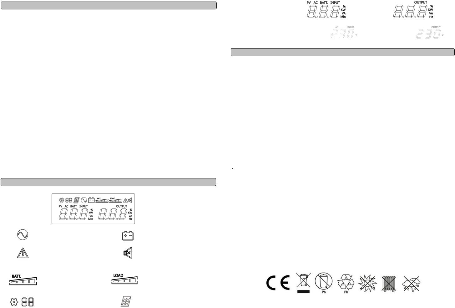
DEFINITIONS FOR ILLUMINATED LCD INDICATORS |
|||||||
LCD Indication
|
|
Line mode |
|
Bat-mode |
|
|
|
|
|
|
|
|
|
Sound disable |
|
|
|
|
(Press the mute key 3s to disable |
|
|
Alarm/Fault |
|
and enable the buzzer sound) |
|
|
|
|
|
|
Bat mode: battery capacity |
|
|
|
|
Line mode: |
|
|
|
|
1. |
Battery charging: cycle lighting |
|
Load capacity |
|
2. |
Battery full charged: lighting |
|
|
|
3. |
Line mode without charger: |
|
|
|
|
battery capacity |
|
|
|
|
Setting Item |
|
PV Mode |
|
|
|
|
|
|
|
|
OUTPUT |
|
|
|
|
|
|
|
AC INPUT(Voltage) |
|
|
|
Initial |
|
|
(Voltage) |
|
|
V |
|
|
|
|
|
|
V |
|
|
|
|
|
|
TROUBLE SHOOTING
|
Problem |
|
Possible Cause |
|
Solution |
|
The UPS does not perform |
|
Batteries are not fully charged. |
|
Recharge the battery by leaving the UPS plugged in. |
|
expected runtime. |
|
Battery is slightly worn out. |
|
Contact Technical Support. |
|
|
|
|
|
|
|
|
|
The on/off switch is designed to prevent |
|
Turn the UPS off. Wait 10 seconds and then turn the UPS on. |
|
|
|
damage by rapidly turning it off and on. |
|
|
|
|
|
|
|
|
|
The UPS will not turn on. |
|
The unit is not connected to an AC outlet. |
|
The unit must be connected to a 220-240V 50Hz outlet. |
|
|
|
|
||
|
|
|
|
|
|
|
|
|
The battery is worn out. |
|
Contact Technical Support. |
|
|
|
|
|
|
|
|
|
Mechanical problem. |
|
Contact Technical Support. |
|
|
|
|
|
|
|
|
|
|
|
Turn the UPS off and unplug at least one piece connected |
|
|
|
|
|
equipment. Unplug the power cord of the UPS then remove the fuse |
|
|
|
Fuse is blown due to overload |
|
compartment beneath the power inlet of the UPS and replace the |
|
|
|
|
blown fuse with a spare one. Lock the compartment back to the UPS. |
|
|
Outlets do not provide power to |
|
|
|
|
|
equipment |
|
|
|
Connect power cord then turn the UPS on. Make sure that your spare |
|
|
|
|
|
fuse meets the specification. |
|
|
|
Batteries are discharged |
|
Allow the unit to recharge for at least 4 hours. |
|
|
|
Unit has been damaged by a surge or spike. |
|
Contact Technical Support. |
|
|
|
The network cable is not connected. |
|
Connect the network cable to the UPS unit and a network port on the |
|
|
|
|
hub. |
|
|
Software is inactive |
|
|
|
|
|
|
Software setting problem. |
|
Please read and follow NetAgent utility instruction during installation |
|
|
|
|
|
||
|
|
|
|
and operation of the NetAgent software, or contact technical support. |
|
|
|
|
|
|
|
|
Fault |
|
|
|
|
|
|
Output Short : |
1. Shut down the UPS |
||
|
Fault code F09 |
2. Your attached equipment may have problems, please remove |
|||
|
Output circuit short. |
||||
|
|
them and check again. |
|||
|
|
|
|
||
|
Fault code F11 |
Battery high: Battery voltage is too high. |
1. Shut down the UPS |
||
|
2.Check the counts of Battery |
||||
|
|
|
|
||
|
|
|
|
|
|
|
|
Battery Low : |
1. Shut down the UPS |
||
|
Fault code F12 |
2. Check the counts of Battery |
|||
|
Battery voltage is too low. |
||||
|
|
3.Check battery connector when use battery packages. |
|||
|
|
|
|
||
|
|
Overload in line Mode: |
|
|
|
|
Fault code F14 |
Your equipment requires more power than the |
Shut off non-essential equipment.If this solves the overload problem, |
||
|
UPS can provide. It will transfer to Bypass |
the UPS will transfer to normal operation. |
|||
|
|
||||
|
|
Mode. |
|
|
|
|
|
Overload in Battery Mode : Your equipment |
Shut off non-essential equipment.If this solves the overload problem, |
||
|
Fault code F14 |
requires more power than the UPS can provide. |
|||
|
|
It will shutdown. |
the UPS will transfer to normal operation. |
||
|
|
|
|
||
|
Fault code F18 |
Fan fail : |
1.Shut down the UPS |
||
|
|
|
2.Replace the fan |
||
|
|
Fan has been damaged. |
|||
|
|
|
|
||
|
|
Over Temperature : |
1. Shut down the UPS. Restart the UPS to Check the fan for operation |
||
|
Fault code F19 |
and if the ventilation hole has been covered |
|||
|
High ambient temperature The LCD will display |
||||
|
|
2. Contact Technical Support. |
|||
|
|
E11 |
|
|
|
|
|
|
All rights reserved. Reproduction without permission is prohibited. |
||
 Loading...