

Page 1
22" PLANER
Model 201
Instruction Manual & Parts List
M-0460224
(800) 274-6848
www.powermatic.com
Page 2

This manual has been prepared for the owner and operators of a Powermatic M odel 201 Planer. Its purpose, aside
from machine operation, is to promote safety t hrough the use of accepted correct oper ating and maintenance
procedures. Completely r ead the safety and maintenanc e instructions before operating or servici ng the machi ne.
To obtain maximum life and efficiency f r om your pl aner , and to aid i n usi ng the machine safely, read this manual
thoroughly and follow all instr uc tions caref ully.
Warranty & Service
WM H Tool Group warrants every product it sell s. If one of our tool s needs service or repair, one of our Authorized
Repair Stations located throughout the United States can give you qui c k servi c e.
In most cases, any one of these WMH Tool Gr oup Repair Stations can aut hor ize warranty repair, assist you in
obtaining parts, or perform rout ine maintenance and major repair on your J E T, Performax, Powermatic, or Wilton
tools.
For the nam e of an Authorized Repair Station in your area, call 1-800-274- 6848.
More Information
WM H Tool Group is consistently adding new products to the li ne. For complete, up- to-date product informati on,
check with your local WMH Tool Group distributor or visit wmhtoolgr oup.com.
Limited Warranty
WM H Tool Group makes ev er y effort to assure that its products meet high quality and durability standards and
warrants to the original retail consumer/purchaser of our products that eac h pr oduc t be free from defects in materials
and workmanship as follows: 1 YEAR LIMITED WARRANTY ON ALL PRODUCTS UNLESS SPECIFIED
OTHERWISE. This warranty does not apply to defects due directly or i ndirectly to misuse, abuse, negligence or
accidents, normal wear-and-tear, repair or alterations outside our facilities, or to a lack of maintenance.
WMH TOOL GROUP LIMITS ALL IMPLIED WARRANTIES TO THE PERIOD SPECIFIED ABOVE, FROM THE
DATE THE PRODUCT WAS PURCHASED AT RETAIL. EXCEPT AS STATED HEREI N, ANY IMPLIED
WARRANTIES OR MERCHANTI B I LI TY AND FITNESS ARE EXCLUDED. SOME STATES DO NOT ALLOW
LIMITATIONS ON HOW LONG THE IMPLIED WARRANTY LASTS, SO THE ABOVE LIMITATION MAY NOT
APPLY TO YOU. WMH TOOL GROUP SHALL IN NO EVENT BE LIABLE FOR DEATH, INJURIES TO PERSONS
OR PROPERTY, OR FOR INCIDENTAL, CONTINGENT, SPECIAL, OR CONSEQUENTI AL DAMAGES ARISING
FROM THE USE O F OUR PRODUCTS . SOME STATES DO NOT ALLOW THE EXCLUSION OR LIMITATION OF
INCIDENTAL OR CONSEQUENTIAL DAMAGES, SO THE ABOVE LIMITATION OR EXCLUSION MAY NOT APPLY
TO YOU.
To take advantage of this warranty, the product or part must be returned for examination, postage prepaid, to an
Authorized Repai r Station designated by our office. P r oof of purchase date and an expl anation of the complaint
must accompany the merchandise. If our inspecti on discloses a defect , W MH Tool Group will either repair or
replace the pr oduc t, or refund the purchase pric e if we cannot r eadily and qui c k ly provide a repair or replacement, i f
you are willing to accept a ref und. W M H Tool Group will return repaired product or replac ement at our expense, but
if it is deter mined there is no defect, or that the defect resulted from causes not within the scope of our warrant y,
then the user must bear the cost of storing and returning the product. This warranty gives you specific legal rights;
you may al so have other r ights which var y from state to state.
WM H Tool Group sells through distributors only. W M H Tool Group reserves the right to effect at any tim e, without
prior notice, those alterations to parts, fittings, and accessory equipment which they may deem nec essary for any
reason whatsoever.
2
Page 3

TABLE OF CONTENTS
Safety Rules.................................................................................................................................................... 4-5
Safety: Decals.................................................................................................................................................... 6
Specifications.....................................................................................................................................................7
Receiving...........................................................................................................................................................8
Installation..........................................................................................................................................................8
Installing Dust Chute......................................................................................................................................8
Inspection...........................................................................................................................................................9
Adjustments........................................................................................................................................................9
Depth of Cut..................................................................................................................................................9
Feed Rate Adjustment...................................................................................................................................9
Belt Tension ..................................................................................................................................................9
Opening Hood .............................................................................................................................................10
Knife Install ation & Adjustment ....................................................................................................................10
The Feed System of Your P laner.................................................................................................................11
Anti-Kickback F ingers.............................................................................................................................11
Infeed Roll..............................................................................................................................................11
Chipbreaker............................................................................................................................................12
Pressure Bar...........................................................................................................................................12
Outf eed Roll ...........................................................................................................................................13
Table Roll s .............................................................................................................................................13
Table Adjustments ......................................................................................................................................14
Test Cutti ng & Trouble-S hooting..................................................................................................................14-16
Maintenance.....................................................................................................................................................17
Lubrication.................................................................................................................................................17
Trouble-Shooting......................................................................................................................................... 18-20
Parts Lists & Exploded Views:
Gearbox Assembly............................................................................................................................... 21-22
Cutterhead Assembly............................................................................................................................23-25
Top Cover Assembly............................................................................................................................26-27
Column Assembly.................................................................................................................................28-29
Table Assembly....................................................................................................................................30-31
Base Assembly.....................................................................................................................................32-34
Electrical Sc hematics:
7.5HP 1Ph 230V.......................................................................................................................................35
7.5HP 3Ph 230V............................................................................................................................... ........36
7.5HP 3Ph 460V............................................................................................................................... ........37
3
Page 4

!
SAFETY RULES
As with all m ac hines, t here i s a cert ain am ount of hazar d invol ved with the use of thi s planer. Use the machine with
the respect and cauti on demanded where safety precaut ions are concerned. When normal saf ety precautions are
overlooked or ignor ed, personal injury to the operator can result.
Read, understand and follow the safety and operat ing instructions found in this m anual. Know the limi tations and
hazards associated with this planer.
Electrical grounding. Make certain that the machine fram e is electricall y grounded and that a ground l ead is
included in the incoming el ectrical serv ice. In cases where a cord and plug ar e used, make certain that t he
grounding plug connects to a suitabl e gr ound. Follow the grounding procedure indicated in the National Elec trical
Code.
Eye safety. Wear an approved safety shield, goggles, or glasses to protect ey es. ( NOTE: Common eyeglasses
are only impact-r esi stant, they are not safety glasses.)
Personal protection. Before operat ing the mac hine, remove tie, rings, watch and other jewel r y and r oll up sleeves
above t he elbows. Remove all loose outer clothing and confine long hair. Prot ective type footwear should be used.
Wher e the noise exceeds the lev el of exposure allowed i n S ec tion 1910.95 of the OSHA Regulations, use hearing
protecti ve devic es. Do not wear gloves.
Guards. Keep the machine guards in place for every oper ation f or which they can be used. If any guards are
removed f or maintenanc e, DO NOT OPERATE t he machine unt il the guar ds are reinstall ed.
Work area. Keep the floor around the machi ne clean and f r ee of scrap m aterial, saw dust, oil and other liqui ds to
minimi z e the danger of t ripping or sl ipping. B e sure t he table is free of all scrap, foreign materi al and tools before
starting to cut. Make cer tain the work area is well li ghted and that a proper exhaust system i s used to minimize dust.
Powermati c r ec ommends the use of anti-skid floor strips on the floor area where the oper ator normally stands and
that each m ac hine’s work area be marked off . Provide adequate work space around the machine.
Avoid accidental starting: Make cer tain m otor switch is in off posi tion bef ore connecting power to the planer.
Operator position. Maintain a balanced stanc e and k eep your body under control at all times. Stand to the lef t
side out of line with the table and make sure no one else is standing in line with the table.
Housekeeping. Before turning on machine, remove all extra equipment such as keys, wrenches, scrap, and
cleaning rags away from the machine
Careless acts. Giv e the work you are doing your undiv ided attention. Looki ng ar ound, carryi ng on a c onversation,
and “horseplay” are car eless acts that can result in serious inj ur y .
Disconnect machine before perf orming any servi c e or maintenanc e or when changing blades. A m ac hine under
repair should be RED TAGGED t o show it shoul d not be used until the maintenance is com plete.
Maintain tools in top condition. Keep tool s sharp and cl ean for saf e and best per form ance. Dull tools increase
noise levels and can cause kic k bac ks and glazed surfaces. B r oken tools or tools that are not securely locked in the
cutterhead can be t hrown out of the planer causing severe or fatal injury as well as sev er e damage to the machine.
Check the condition and adjustment of the tool s before making any cuts. F ollow the sharpening instructions on knife
grinding and jointing, installing and adjustments.
Short sto ck: Do not attem pt to plane boar ds shorter than 12" (305mm ) in l ength without butt ing a board of equal
thickness behind it to help it through the pl aner. B e sure the last board of a butted sequence is 12" (305mm) long or
longer.
Stacked boards: Do not feed stacked boards through a pl aner ; a kickback can occur causing severe or fatal i njury.
4
Page 5

If stock sto ps feedi ng: I f t he board being pl aned stops feedi ng, disengage or turn the feed off and turn the power
off . W ait unt il the cutterhead comes t o a compl ete stop before lowering the tabl e to remov e the board. NEVER
lower the tabl e with the power on and the stock still in the machine, as a kickback can occur.
Hand safety. Keep hands outside t he machine. NEVER reach under the guards to try to clear stock that stops
feeding. Do not clear c hips and sawdust with hands; use a brush. Do not have any part of t he hands under t hat part
of the board that is over the table when starting a cut ; the infeed roll will engage the board and force it down against
the table causing a pinching ac tion.
Cutterhead rotation: Be sure cutterhead rot ates under power in a countercl ockwise di rection when viewed from
the mai n drive motor side.
Material condition: Do not plane boards with l oose knots or wit h nai ls or any foreign m at eri al on i ts surf ace. Knif e
impact on t hese obj ect s can cause the kni ves to be pul l ed out and c ause them to shatt er agai nst the c hipbr eaker or
pressure bar. Twisted, warped, or wi nd in stock should f i rst be joi nted on one surf ace befor e attem pting t o plane a
parallel surface on t he planer. Serious stock flaws cannot be removed by use of a planer alone.
Machine cap acity: Do not make any c uts requiri ng mor e power than is av ail able on the m achi ne. Do not attempt
to feed two boards side by side (multiple board surfacing) on any m ac hine not equipped with sectionalized infeed roll
and chipbreaker. NOTE: The 22" Pl aner i s rated at 7.5 horsepower with max im um cutt erhead speed of 4800 RPM.
DO NOT equi p your pl aner wit h a m ot or of hi gher horsepower or run the c utt erhead i n ex cess of 4800 RP M. Doi ng
so voids the warranty and Powermatic holds it sel f harmless from any inj ur y that may r esul t.
Machine adjustment s: M ake all machine adjustments with power off except feed rate.
Job completion. I f the operat or leaves the machi ne ar ea for any reason, the planer should be turned "off" and the
cutterhead should c ome to a complete stop before his departur e. In addit ion, if the operat ion is complete, he should
clean the planer and the work area. NEVER clean the planer with power "on" and never use the hands to clear
sawdust and debris; use a brush. Disconnect mac hine fr om power source before c leaning.
Replacement p art s. Use only Powermat ic or factory author ized replac ement part s and accessories; otherwise the
warranty and guarantee i s nul l and v oid.
Misuse. Do not use t his Powermatic planer f or other than its intended use. If used for ot her pur poses, Powerm atic
disclai ms any real or impl ied warranty and holds i tself harmless for any injury or damage which may result from t hat
use.
If you are not thor oughly familiar with the operation of planers, obtain advice from your supervisor, instructor or
other quali fied per son.
Drugs, alcohol, medication. Do not operate this m ac hine while under t he influence of drugs, alcohol, or any
medication.
Health hazards. Som e dust c r eated by power sanding, sawing, grinding, drilling and other construction activi ties
contains chemicals known to cause cancer , birth defects or other r epr oduc tive harm. Some exampl es of these
chemic als are:
* Lead from lead-based paint .
* Crystalline silica from bricks and cement and other m asonry pr oduc ts.
* Arsenic and chromium from chemi c ally-treated lumber.
Your risk from t hese exposures varies, depending on how often you do this type of work. To reduc e y our exposure
to these chemicals, work in a wel l-ventil ated area, and work with approved saf ety equipm ent, such as those dust
masks that are speci fically designed to fi lter out microscopic parti c les.
5
Page 6

Familiarize yourself with the following safety notices used in this manual:
!
CAUTION: (This m eans that if pr ec autions are not heeded, it may result in minor or moderate i njury
and/or possible machine dam age)
!
WARNING: (Thi s means that if precautions are not heeded, it could result in serious injury or
possibly even death).
!
SAFETY
Familiarize yourself with the location and content of this decal on y our machine.
!
1. Read instruction manual before operating machine.
2. Do not operate wi thout all gu ards properl y installed.
3. Remove or fasten loose articles of clothing such as neckties, etc.
Contain l ong hair.
4. Remove jewelry such as finger rings, watches, bracelets, etc.
5. Use approved safety glasses and/or face shield to protect eyes, and
use other personal safety equipment as required. Do not wear
gloves.
DO NOT REMOVE OR OBSCURE THIS LABEL
6. Disconnect machine from power source before making any
adjustments or cleaning chips away from machine.
7. Keep the floor around machine clean and free from scraps,
sawdust, oil and grease to minimize the danger of slipp ing.
8. Do not operate this machine w hile under t he influence of alc ohol
or drugs.
9. Failure to comply with these warnings may result in serious
personal injury.
6
Page 7

SPECIFICATIONS: Model 201, 22” Planer
Table with standar d extensions........................................................................................................................ 28” x 38”
Maximum cutting width.............................................................................................................................................22"
Maximum thickness.................................................................................................................................................1/4"
Full wi dth depth of c ut............................................................................................................................................3/16"
Minimum planing lengt h............................................................................................................................................10"
Number of knives ........................................................................................................................................................4
Cutterhead speed ..........................................................................................................................................4800 RPM
Cuts per minute...................................................................................................................................................19,200
Cutterhead diameter.............................................................................................................................................3-1/4"
Blade size ............................................................................................................................22-1/8" L x 7/8" W x 1/8" T
Feed rate...................................................................................................................................................20 & 30 FPM
Overall dimensions................................................................................................................ 32-1/4" W x 50" H x 50" L
Motor......................................................................... 7.5 HP, 3 Ph, 230V or 7.5 HP, 3 Ph, 460V or 7.5 HP, 1 Ph, 230V
Shipping weight..............................................................................................................................................1,197 lbs.
NOTE: T he above speci fications were current at the time this m anual was published, but because of our poli c y of
continuous improvement, Powermatic reserves the right t o c hange specifications without notice and wit hout
incurring obligat ions.
7
Page 8
RECEIVING
Open shipping crate and check for shipping damage.
Report any damage immediately to your distributor.
Read the instruction manual thoroughly for assembly,
maint enanc e and safety i nstr uc tions.
Contents of crate:
1 planer
1 dust chute w/ hardware
4 special hex head screws w/ hex nuts
4 foot pads w/ hardware
1 knif e- set ting gauge
1 6mm hex wrench
1 8mm hex wrench
1 10mm hex wrench
1 12mm & 14mm wrench
1 22mm & 24mm wrench
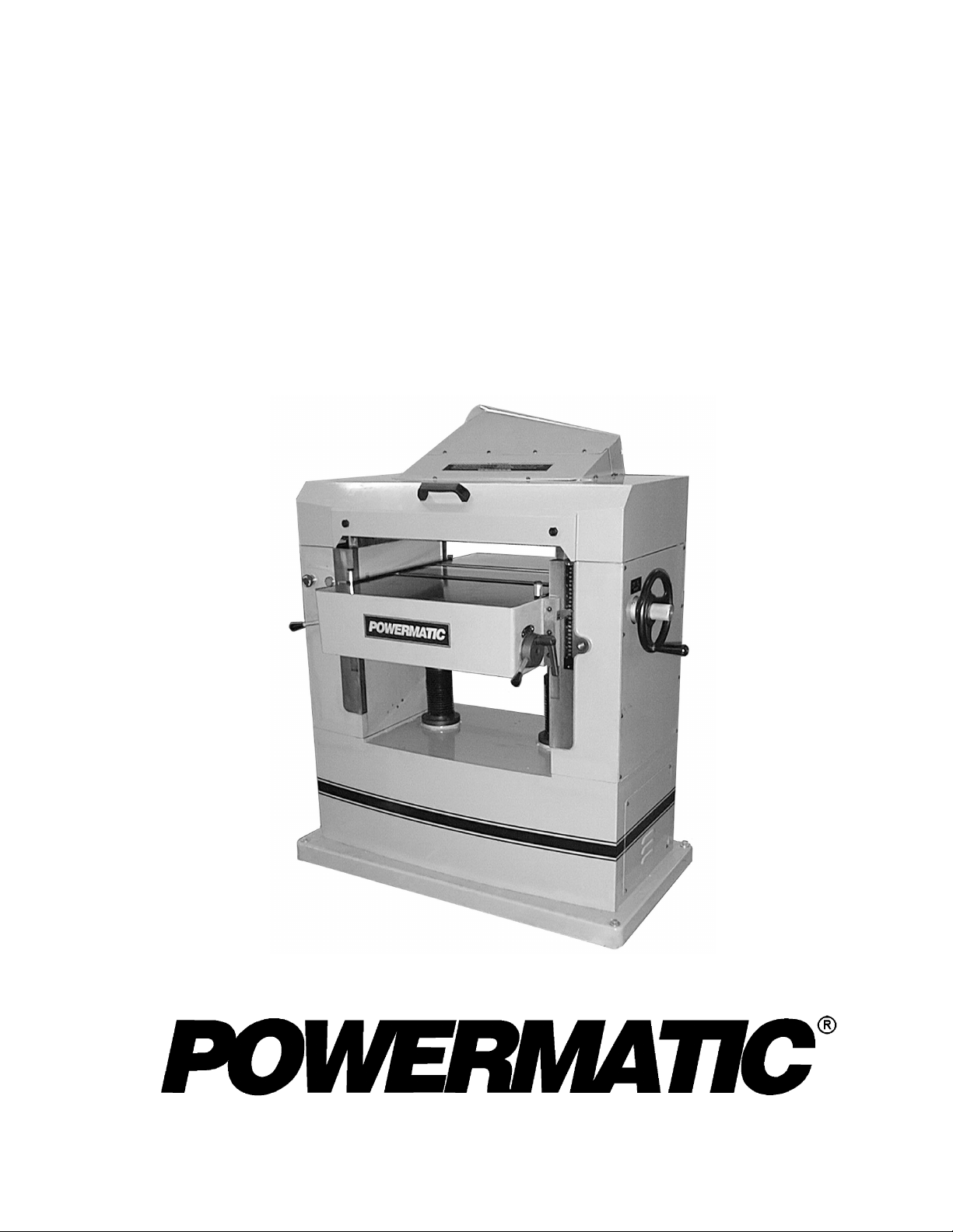
INSTALLATION
Remov e the screws holding the base of the m achine to
the skid. Use t he lifti ng eyes on front and back of t he
planer for hoisting it off the skid. See Figure 1. Make
sure the hex nut s are tight ened before l if ti ng. The ey es
should be removed once the planer is situated.
Place the planer on a solid foundation, preferably a
concrete floor. The four foot pads should be placed
beneath the corners and the screws and hex nuts used
for l ev el i ng adj ustm ents. A lt ernat el y, y ou can secure the
machine to the floor by using lag screws through the
holes in the base.
The machi ne area should be clean, dry, well v enti lated,
and well lighted. Since planers can create noise
problems, the site selection should be one which
minimizes reverberant sound from walls, ceilings and
other equi pment. Elect ricals should be install ed so t hat
they are protec ted f r om dam age and ex posure. Be sure
to properly gr ound the machi ne frame.
Exposed metal parts have been given a protective
coating at the factory. This should be removed with a
soft rag and kerosene or a good commercial solvent.
Do not use an abrasive pad.
Powermatic strongly recommends that an exhaust
system be used with this machine. It should be of
sufficient volume for this size planer. If an exhaust
system is not used, the user is cautioned against the
health haz ar d and the lim itations in the OSHA r egulation
for employee or student exposure to dust particles.
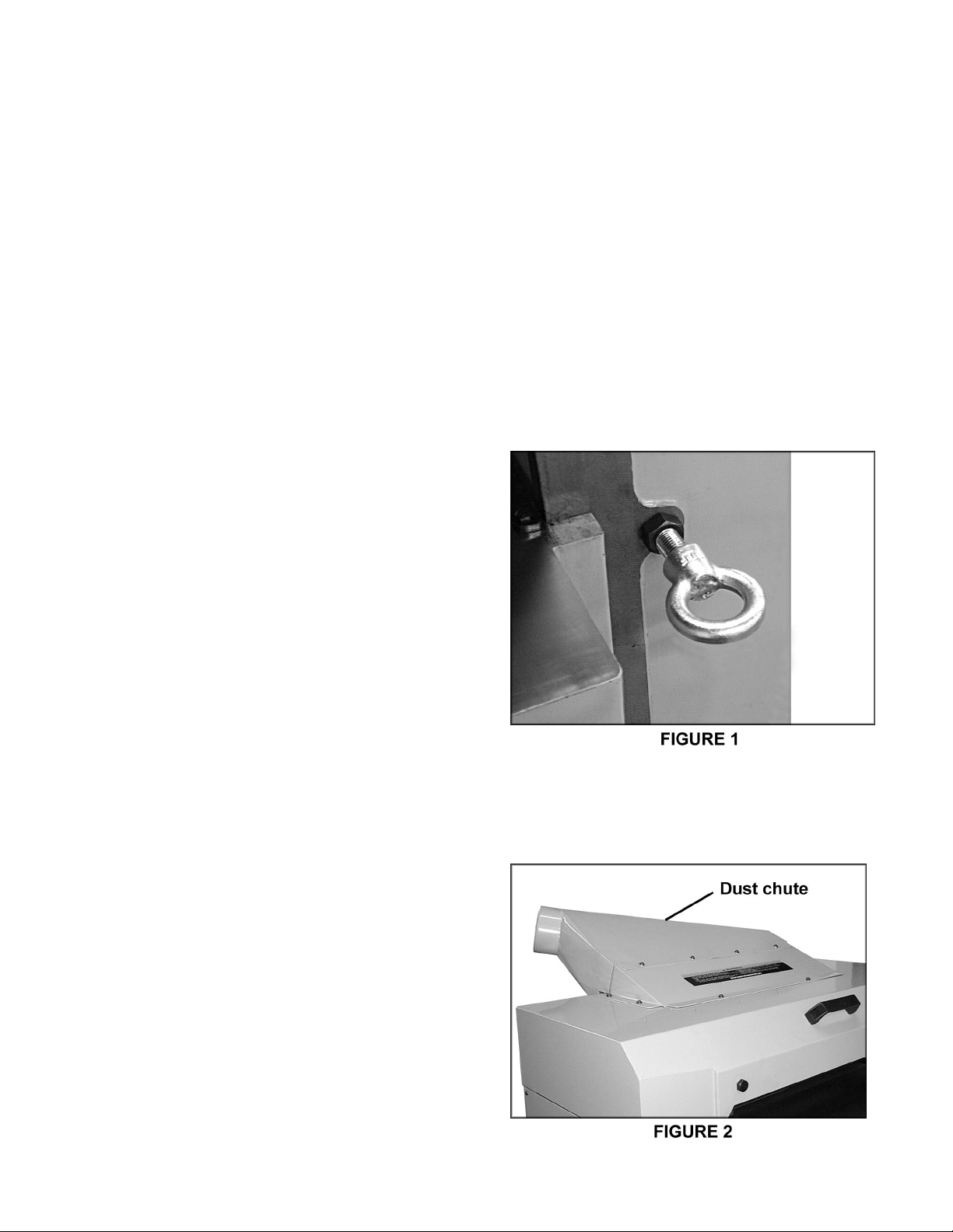
INSTALLING DUST CHUTE
Mount the dust chute with the eight M6 x 10mm hex
screws, eight spring washers, and eight flat washers.
See Figure 2.
8
Page 9
INSPECTION
Before putting power to the machine, check that all
screws are tight, that all mechanical functions work
freel y and that the cutterhead t urns freely without knif e
contact wit h the chipbreaker or pr essure bar.
ADJUSTMENTS
Tools required
Philips screwdriver
Hex wrenches (provided)
Open-end wrench (provided)
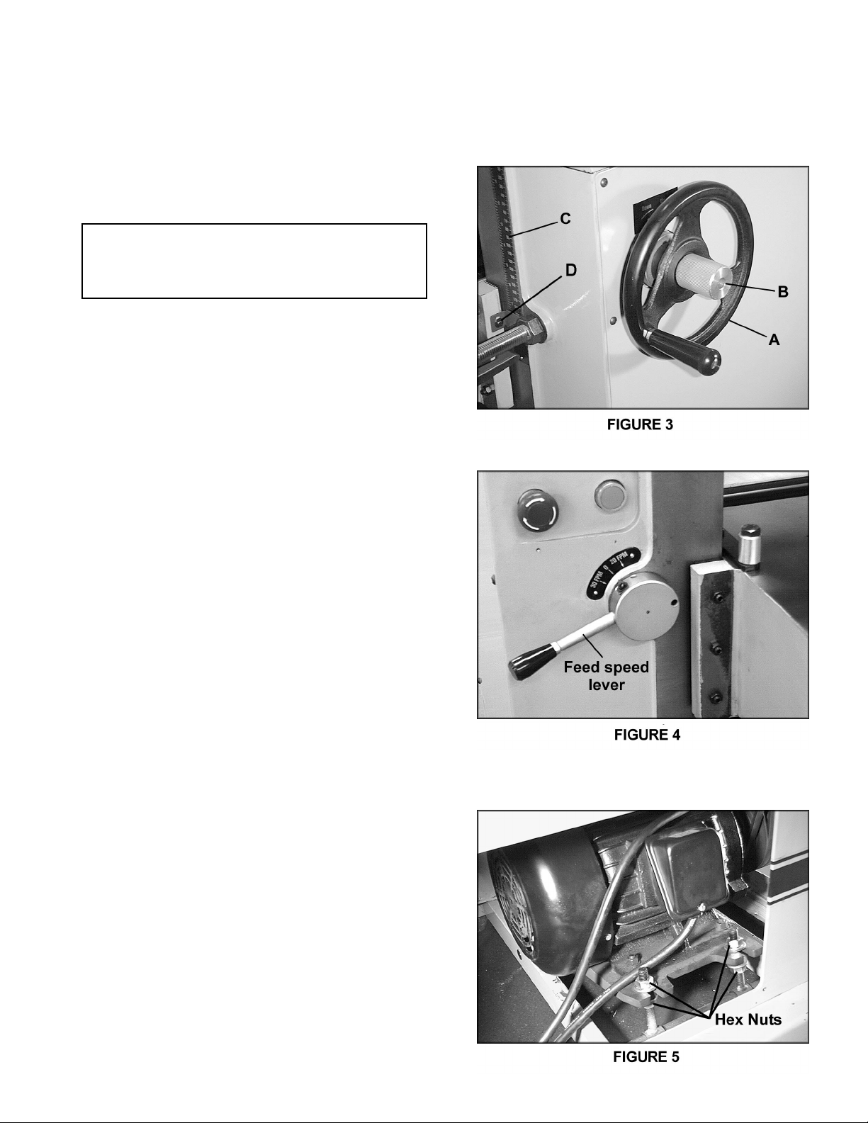
DEPTH OF CUT
Depth of cut is controlled by raising or lowering the
table. T his is done by using the handwheel (A), shown
in Figure 3.
1. Loosen the lock knob (B ) .
2. Raise or lower the table to the desired position
(clockwise to raise). One revolution of the handwheel
equals 1/16". The distance can be read on the scale
(C).
3. Retighten lock knob (B).
4. The pointer ( D) can be adjusted i f the scale should
ever need r ecalibrating.
FEED RATE ADJUSTMENT
The Model 201 is equipped with selectabl e feed speed
rolls t hat feed stoc k at 20 and 30 feet per minute. To
adjust speed, turn lever shown in Figure 4.
IMPORTANT: Always change speeds while the
machine is running.
BELT TENSION
1. Disconnect m achine f r om power source.
2. Remov e lower rear panel of machi ne, and use the
hex nuts to adj ust tension. See Figur e 5. Adjust motor
plate up or down until correct belt tension is achiev ed.
To lower motor plate, loosen lower nuts and tighten
upper nuts. To raise motor pl ate, do the opposit e.
3. Correct tension is obtained when there is
approxim ately 1/4" defl ection in the center span of the
belts using light f inger pressure.
4. Re-tighten the nuts and replace panel.
9
Page 10
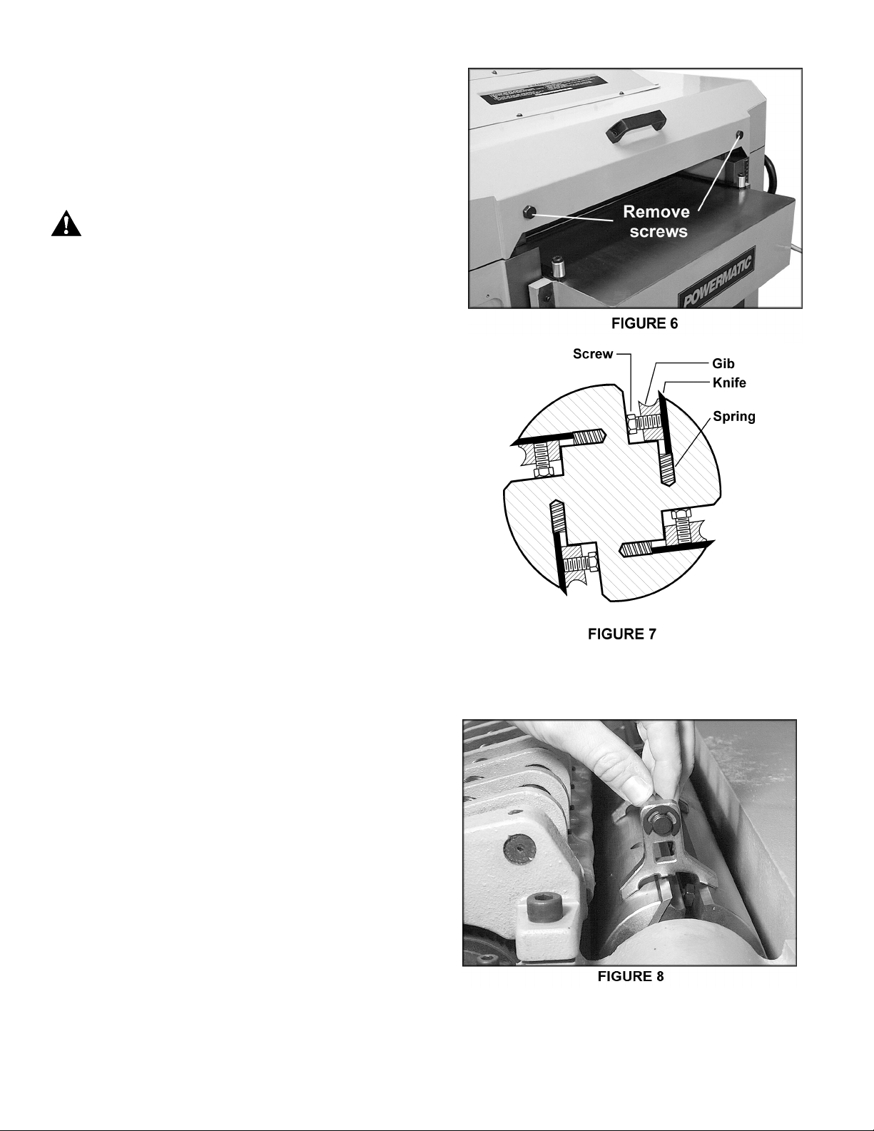
OPENING HOOD
To open t he hood for acc ess to the cutterhead, rem ov e
the two hex screws with the 22mm wrench provided.
See Figure 6.
KNIFE INSTALLATION & ADJUSTMENT
CAUTION: Use care w hen placing han ds near
!
knives as they are extremely sharp and can
cause severe cuts.
Installi ng knives on a planer is an exac ting process. If
the kni ves ar e not to be j ointed and ground, end-t o-end
and knif e-to-knif e relat ionship must be hel d within .001"
(.03mm) for accurate and smooth planing. To help
avoid cutterhead distortion in changing out a set of
kniv es, rem ove and repl ace the knif e in one slot before
changing the next knife.
Any knif e adjustm ent or replacem ent should be done to
all four kni v es at the sam e tim e. Fai lur e to do thi s may
result in an out -of-bal ance cutterhead which can lead to
bearing f ailure.
1. Disconnect m achine f r om power source.
2. To remove k nife, loosen the six hex head screws.
See Figure 7.
3. The knife is spring loaded and will rise up in the
slot. Carefully rem ove knife f rom cutterhead by lifting
straight out. Remove gib and springs, and clean any
dust, pit ch or accumul ated foreign mat ter from t he sl ot
and the gib.
4. Replace the springs and gib into the slot, then
insert new knife and loosely snug the six hex head
screws.
5. Carefully place the knife-setting gauge until it
contacts t he cut terhead, as shown in Figur e 8. Thi s will
hold the high point of the knives to the proper height
above the cutterhead (approximately 1/8” or 3.18mm).
Use the gauge at both ends of the kni fe, then check t he
center section to be sure it is even. If it is low, try
backing off slightly on the center gib screw to allow
blade to com e up. Gentl y tap blade down with piece of
wood until i t conform s to the gauge height. Recheck the
full length of the knife.
NOTE: If all knives have been removed, a new set
must be installed with the gib screws lightly snugged
down but not full y t ight ened. A ll kni ves and gibs should
be in place before tightening. Locking one knife in
without the others in position can cause cutterhead
distortion. The tightening process should proceed
working from the center out on each knife and after
locking al l gib screws once, repeat the same sequence
until all screws are equally tight.
10
Page 11
WARNING: After installing kn ives, re-check
!
all gib screws. Loose gib screws can result
in knives being t hrown o ut of th e cutterhead,
causing severe damage to the machine an d
possible serious or fatal injury to the operator
or bystanders.
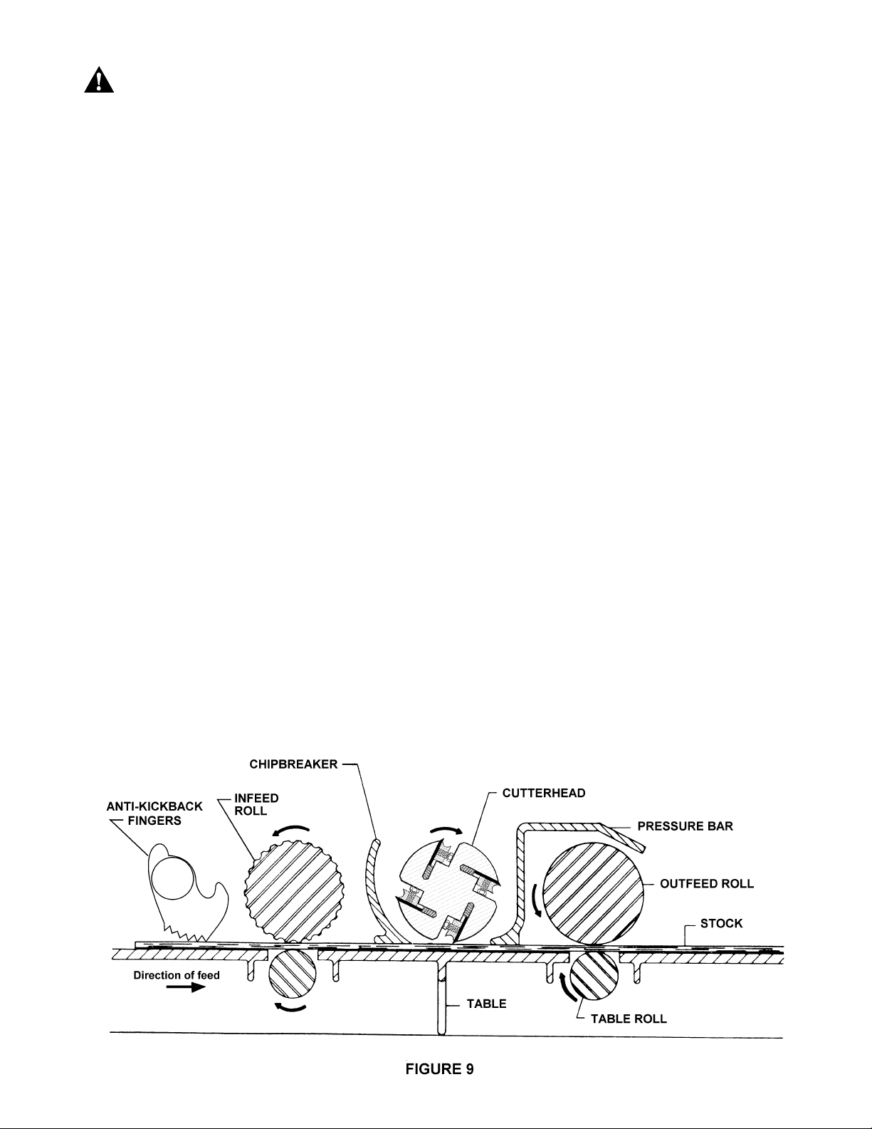
THE FEED SYSTEM OF YOUR PLANER
(Figure 9)
1. Anti-kickback fingers
2. Infeed roll
3. Chipbreaker
4. Cutterhead
5. Pressure bar
6. Outfeed roll
ANTI-KICKBACK FINGERS
Anti-kickback fingers help prevent stock from being
thrown from the machine. These fingers operate by
gravi ty and should be inspected before each day's use
for pitch or gum buildup. The fingers must operate
freel y and move independently for c or r ec t operation.
INFEED ROLL
The funct i on of t he infeed roll i s to f eed the mat eri al into
the machine. It is a corrugated, sectional roll with
approximately 5/16" independent movement of each
section to acc omodate m ultiple board surfacing.
To provide proper drive, it should be set so that the
bottom of its arc is 1/16" (1. 6mm) below the arc of the
cutterhead knives. The infeed roll is under spring
tension and this tension must be sufficient to feed the
stock uniformly through the planer without slipping but
should not be so tight that it causes damage to the
boards. The tension should be equal at both ends of
each roll.
11
Page 12
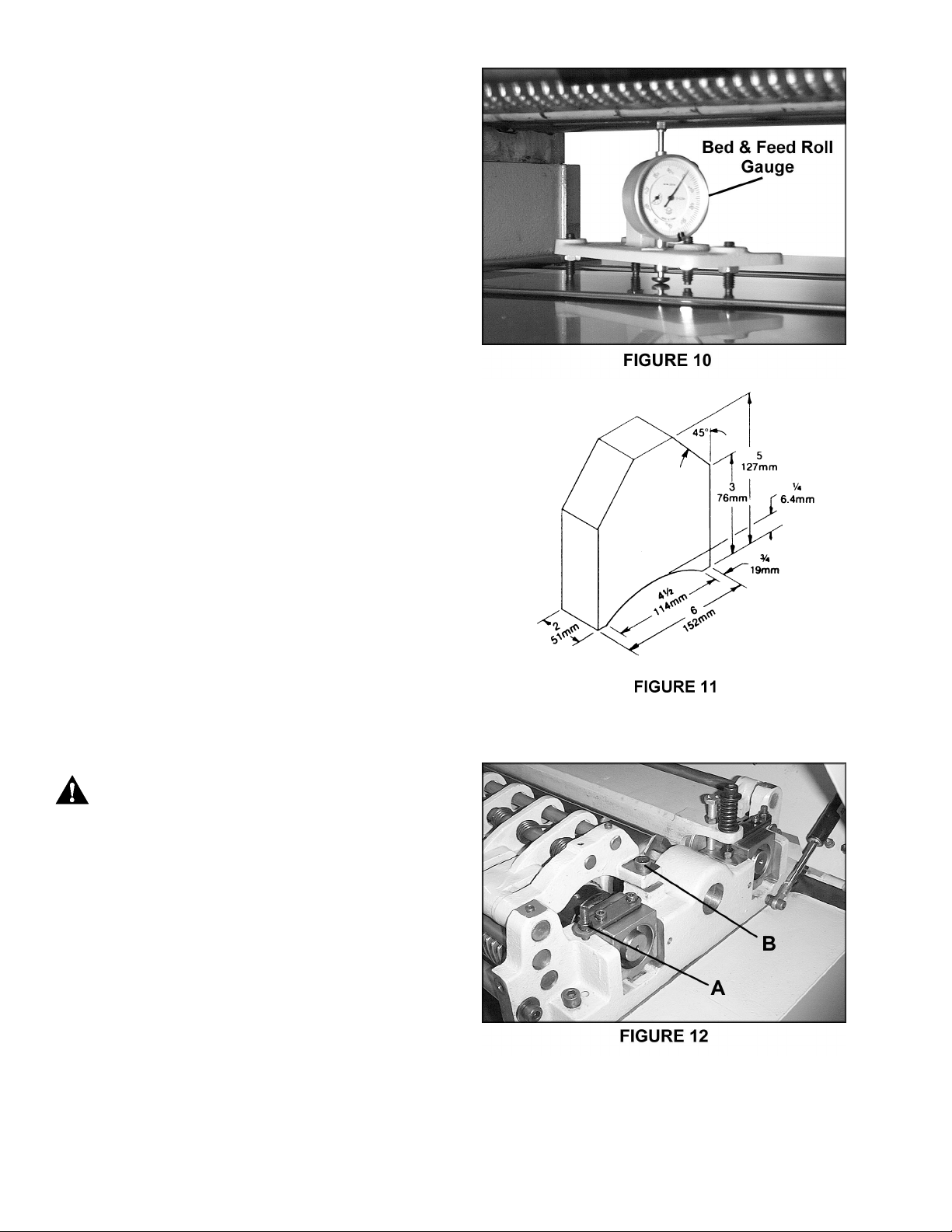
To adjust the infeed roll:
1. Place a bed and feed roll gauge (accessory
#2230002) under a k nif e in t he cutterhead and r aise the
table unti l the gauge c ontact s the kni f e at the apex of i t s
curv e. See Figur e 10.
NOTE: If a bed and feed roll gauge is not available, use
a finished block of wood with notches cut out for the
table rolls, and a feeler gauge. See Figure 11 for an
example of a wood bloc k used for a gauge.
2. Move the gauge to the extreme left side of the
infeed roll and check the measurement. It should be
1/16" below the kni fe measurem ent. It if is not, correct
with the adjustm ent screws (A) on top the side panels,
shown in Figure 12.
3. Move the gauge t o the ex t rem e opposite end of the
infeed r oll and check . Make necessary adjustments.
It is important that t he setting on bot h si des of the infeed
roll be the same height to help avoid skewing of the
material as it is fed thr ough the machi ne.
CHIPBREAKER
The chipbreak er is a sectionali zed type made of 1" side
spring-loaded secti ons mounted on a bar which swings
concentric with the cutterhead. The functions of the
chipbreaker are to break chips into small pieces, help
avoi d splinteri ng of the wood, hel p avoid board bounc e
on thinner boards, t o direct the fl ow of chi ps out of the
machine, and to perm it multiple board surfacing.
The chipbreaker in its free position should be 1/32"
(.8mm) below the cut ting arc of the kni ves.
CAUTION : A chi pbreaker set too low may
!
prevent sto ck f rom feeding into t he machine.
Using the same m ethod as indicated f or the infeed roll,
adjust the chipbreaker free position using a bed and
feed roll gauge and adjust the screws (B) in the piv ot
arm at each end if necessary. See Figure 12. It is
important that each end be the same height to help
avoid skewing of the material as it is fed through the
machine.
NOTE: If the infeed roll setting is altered, the
chipbreaker must be re-adjusted.
PRESSURE BAR
Most planing pr oblem s can be traced to im pr oper setting
of the pressure bar. Its function is to hold down the
material after it passes under the cutterhead and
throughout the rem ainder of the cut. Its basic setting is
to be in line with the arc of the cutterhead knives.
12
Page 13

If it is too high, a shallow "clip" will occur at each end of
the board. If it is too low, stock will not feed through.
Use a bed and feed roll gauge t o set t he full lengt h of
the pressure bar to be .000-. 001" (.02mm) above the arc
of the cutterhead. Figure 13 shows the height
adjustment screw (C) and the spring t ension adjustm ent
screw (D) for the pressure bar. This initial setup is a
starting point and final adjustment m ay have t o be made
during a test cut.
OUTFEED ROLL
The outf eed rol l i s of smooth, one- piece construct ion to
help avoid marring the f inished surface of the materi al
being cut. I ts f unc ti on i s to conti nue to feed the mat eri al
through the m achine af ter it l eaves the i nfeed rol l. The
correct free position setting is 1/32" (.8mm) below the
arc of t he c utterhead kni ves.
Use a bed and feed roll gauge to check the outf eed roll
in the same manner as the infeed roll. Adjust as
necessary using the screws shown in Figure 13.
TABLE ROL LS
The Model 201 Planer has two table rolls which help
reduce friction of the stock on the table as it feeds
through the machine. It is not possible to give exact
height setting of the table rolls because each type of
wood behaves dif ferently. As a general rule, however,
when planing rough stock, the table rolls should be set
high and when planing smooth stock the table rolls
should be set low. Height should should normally range
between .005" to .015".
The planer is equipped with a quick set table roll
adjustment . W ith a singl e lev er, you can rai se the rolls
from their finishing board height to a roughing board
height. See Figure 14. The range is 0.00 to .060”
To adjust the hei ght of the tabl e roll s, loosen the handle
(A) and tur n t he lever (B) . Re- ti ghten t he handl e to l ock
the setting.
If t he table rol ls should need further adjustm ent:
1. Position the lever (B-Fig. 14) to zero setting.
2. Use a bed and feed roll gauge and zero the
indicat or to the tabl e. Place t he gauge over t he extreme
right side of the table rol l and fi nd the high point of the
roll arc.
3. The standard sett i ng i s .008" ( .2m m ) ; i f t he readi ng
is greater or less than this reading, reach below the tabl e
and loosen t he hex nut (C) which i s above the c am (D)
Rotate the hex screw (E) to position the .008" setting.
See Figure 15.
13
Page 14

4. Repeat the process for the left side, and then recheck the right side. It is import ant that both ends of the
table r olls be t he same height to help prevent skewing of
the board as it feeds through the machine.
5. Re-t ight en the hex nut s (C-Fi g. 15) on both ends of
the table roll. Repeat for ot her roll.
TABLE ADJUSTMENTS
The planer table is raised and lowered by twin screws
supported on bearings, and is guided by machined
surfaces on the side panels. The fi t-up to prevent the
table f rom r ocki ng i s control l ed by t wo gibs in front. See
Figure 16. These gibs should be adjusted individually
using the gib screws provided so that the ways are
lightl y contacting on al l four surfaces. The gibs should
be tight enough to prevent rocking or mov ement of the
table when the planer is in operati on.
To do accurate plani ng the table must be parallel with
the cutterhead. Lack of parallelism results in a taper
over t he width of the board. To check parallel ism do the
following:
1. Use a bed and feed roll gauge, or a wood gauge
block, to check parallelism at each end of the
cutterhead.
2. If the table is not parallel, pl ace the gauge at the
end that needs to be raised. Loosen the three socket
head screws (A) beneath the table, as shown in Figure
17, place a rod i nto one of t he open holes (B), and turn
the shaft (C) to r aise the table unti l the gauge contacts
the cutt erhead. O r, the sam e ef f ect can be achi eved by
lowering the ot her si de of the table.
(NOTE: This adjustment may generate the need to
recalibrate the table height poi nter.)
3. Re-tighten the screws (A).
TEST CUTTING &
TROUBLE-SHOOTING
Using a piece of semi-f inished stock, set up f or a 1/ 16"
(1.58mm) deep cut with the quick-set adjustment at
zero. Start the m achine and, standing to the l eft-hand
side, begin feeding the stoc k into the machine.
WARNING: Never stand d irectly behind stock
!
or allow anyone else to do so, and do not
bend down to see how sto ck is feeding.
Should a kickback occur, serious or fatal
injury could result.
The infeed roll should take the material and force it
under the chipbreaker and cutterhead. If the material
feeds through effortlessly, examine the finished cut
carefully for imperfections.
14
Page 15

Learning to read a board for imperfections will save
hours in adjusti ng a planer to operate pr operly.
Following are some problems that may arise and their
probable solutions:
FEED RESTRICTION:
This i s caused either by the tabl e roll s being set too l ow
for roughing operations or from a low pressure bar.
About 90 percent of the time, the pressure bar is too
low. As the sharp edge of the planer kniv es wear, you
must compensate for this wear by raising the pressure
bar an equal am ount on each side. Your f irst i ndicat ion
of kni f e wear is hesit ati on i n feed of the mater ial through
the m achine after it leaves the c orrugated infeed rol ler
on its way out of the machine. Turn machine off and
adjust the pressure bar acordingly. The material will
free up and feed through smoothly.
CAUTION: Never att empt pressure b ar
!
adjustment while the machine is running.
Feed restri ction can also occur due to pi tch buildup on
the tabl e. Be sure the table surf ace is clean. Dusting
the surface with talc occasionally will aid in smoother
feeding and help prevent pit c h buildup.
WASHBOARD FINISH:
A ver y pronounced washboard fini sh down the full length
of the board results from one knife being too high and
forced t o do all the cutti ng. See Fi gure 18. Reset the
high knife accordingly.
CLIP MARKS:
If "clip" m arks occur 6" (152 mm) in from each end of
the board, the pressure bar i s too hi gh. See Fi gure 19.
Turn both ri ght and lef t hand adj usting screws the same
amount, 1/4" turn clockwise or less, and take another
1/16" (1.58 mm) deep cut. Re-ex amine the boar d.
Continue the operate-adjust procedure until the clip
marks disappear. Should the boar d fail to feed through,
back off sl i ghtl y on bot h adjusti ng screws until f eedi ng i s
smooth and the imperfections do not reappear. Lock
the pressure bar adjusting screws with the jam nuts
provided.
SNIPES:
If snipes appear on each end of the m aterial , as shown
in Figure 20, a table roll is too high causing a sl ight lift of
the m aterial as it passes through the m ac hine. Norm ally
these snipes are more noti ceable on the trailing end of
the board than on the lead end, and most often occur
during planing of rough lumber. Table rolls must be
elev ated f or running rough or r esaw lumber through the
machine. W hen material is turned over to surf ace the
other side, and you negl ect to l ower the table roll s for a
fini shed c ut, then def i ni te sni pes will appear on the ends
of the materi al.
15
Page 16

CHATTER:
Chatter marks usually appear on thin material. See
Figure 21. Ev en at t heir lowest point , the table r olls are
too high t o handle thin m aterial. S olve the pr oblem by
either using a sl ave board or maki ng an auxiliary table
out of F orm i ca count ert op m ateri al , cl eati ng at eac h end
of the t able to keep i t stationary.
TAPERS:
If t he m achi ne pl anes a taper across the f ul l width of the
board, as shown in Figure 22, the table is not parallel
with the cutterhead. First check that all knives are
properly installed with equal protrusion from the
cutterhead. If they are, then the table itself must be
adjusted. See “Table Adjustment” above.
TWISTING:
If m ater i al t wists while f eedi ng t hrough the pl aner, ei ther
the tabl e rolls, pr essure bar, or outfeed roll may be out
of l ev el. Place t he bed and feed r oll gauge ( or a gauge
block) on the table directly under the right end of the
infeed roll, move table up until light contact is made
between roll and gauge. M ov e t he gauge to t he l ef t end
and check. Repeat thi s process under the chipbreaker,
pressure bar, and outfeed roll until the problem is
discovered. Generally the pressure bar will be out of
level due to its constant adjustm ent to compensate for
knif e wear. At thi s point , l evel the pressure bar (or other
part of the planer) and proc eed with operation.
HALTED FEEDING:
If the infeed roll takes stock away from you while
feeding, then feeding stops immediately, the
chipbreaker is too low, causing material to hit high on
the heel. Reset t he chipbreaker.
In a simi lar situat ion, the i nfeed rol l takes the stock, the
chipbreakers l ift, and j ust as you hear t he knives contact
the material, then it stops feeding. In this case the
pressure bar is too low. Reset the pressure bar
according to instruction in this manual.
16
Page 17

MAINTENANCE
Periodic or regular inspections are required to ensure
that the m achine i s in proper adj ustment , that all screws
are ti ght, that belt s are in good condition, that dust has
not accumulated in the electrical enclosures, and that
there are no loose or worn elec trical connections.
Buildup of sawdust and other debris can cause your
machine to pl ane inaccuratel y. Peri odic cleani ng is not
only recommended but mandatory for accurate planing.
Close-fitting parts, such as the table locking rods, the
cutterhead slot and gibs, should be cleaned with a cloth
or brush and non-flammable solvent and freed from
clinging foreign matter.
Remov e resin and other accumulations from feed rolls
and table with a non- flammable solv ent.
Periodic ally chec k all the chains for proper tension and
adjust accordingly if requi r ed.
TIP: If a foreign object nicks the knives, instead of
throwing them away or tryi ng to grind out the deep ni ck,
simply stagger the kni v es in the head, mov i ng one knife
no more than 1/ 4” t o the ri ght and another knife no more
than 1/4” to t he left. The nic k will not be noticeable.
LUBRICATION
The gear box oil should be changed once a year. The
drain plug (A) is shown in Figure 23. Refill the gear box
with 60-90 weight gear oi l through the f ill hole (B). The
sight glass (C) should be checked periodically and oil
added as necessary.
The recommended lubrication for roller chains used in
medium to slow speed operation is to simply wipe the
chain clean. When there i s an appreci able build up of
dust, dirt or wood shavings, use an oil cloth but nev er
pour the oil directly on the chain. Over-oiling defeats
the purpose of the l ubri cat i on, sinc e it tends t o invi te t he
collecting of dust, shavings, etc. and works into
member s of the chain. This hastens wear and leads to
premature replacem ent.
The bearings on the cutterhead are factory lubricated
and sealed. They require no fur ther attent ion.
17
Page 18

TROUBLE-SHOOTING: OPERATING PROBLEMS (201 Planer)
PROBLEM POSSIBLE CAUSE SOLUTION
Snipe 1. Table rollers not set proper ly. 1. Adjust rollers to proper height.
2. Inadequate support of long boards. 2. Support l ong boards with extension
(NOTE: Snipe can be rollers.
minimi z ed but not 3. Unev en feed rol l pressure front to back. 3. Adjust feed roll tension.
eliminated. ) 4 Dull kniv es 4. Sharpen knives.
5. Lumber not butted properl y . 5. Butt end t o end eac h piece of stoc k
as they pass through.
Fuzzy Grain 1. Planing wood with a hi gh moisture 1. Remove high moisture content
content. from wood by drying.
2. Dull k nives. 2. Sharpen knives.
Torn Grain 1. Too heavy a cut. 1. Adjust proper depth of cut .
2. Knives cutting against grai n. 2. Rev iew planing for finish.
3. Dull k nives. 3. Sharpen knives.
Rough/Raised Grain 1. Dul l knives. 1. Sharpen k niv es.
2. Too heavy a cut. 2. Adjust proper depth of cut .
3. Moisture c ontent too high. 3. Remove high moisture content
from wood by drying.
Rounded glossy 1. Dull k nives. 1. Sharpen or replace knives.
surface
Poor feeding of lumber. 1. Inadequate feed roll pressure. 1. Adjust f eed r oll tensi on. If pr oper
tension cannot be achieved,
replace feed roll s.
2. Planer bed rough or dirty. 2. Clean pitch and residue, and wax
planer bed.
3. Transmission v- belt sli pping. 3. Tight en transmission v-belt.
4. Surf ac e of feed rolls too smooth. 4. Lightly roughen the feed roll
surface with sandpaper.
18
Page 19

TROUBLE-SHOOTING: MECHANICAL & ELECTRICAL PROBLEMS
(201 Planer)
PROBLEM POSSIBLE CAUSE SOLUTION
Uneven dept h 1. Knife projection 1. Adjust knife projecti on.
of cut si de to side 2. Cutterhead not level with bed. 2. Level bed.
Board thickness 1. Depth of c ut scale incor r ec t. 1. Adjust depth of cut scale.
does not match dept h
of cut scale
Chain jumping 1. Inadequate tensi on. 1. Adjust chain tension.
2. Sprockets misali gned. 2. Align sprock ets.
3. Sprockets worn. 3. Replace sprockets.
Machine will not start/ 1. Unit not plugged in. 1. Verify unit is connected to power.
restart or repeat edly 2. Overload automatic 2. W hen planer overloads on the circuit
trips circuit breaker or reset has not reset. breaker built into the motor starter, it takes time for
blows fuses the machine to cool down before r estart. Al low unit
to adequately cool before attempt ing restart. If
problem persi sts, c hec k amp setti ng on the motor
starter inside the el ec trical box.
3. Planer frequently trips. 3. One cause of overload trips which are not
electrical i n nature is too heavy of a cut. The
solution is to take a lighter cut. If too deep of a cut is
not the problem, then c hec k the amp setting on the
overload relay. Match the full load amps on the motor
as noted on the motor plate.
If am p setting is corr ec t then there is probably a
loose electrical lead or a failed component . See
items 9 & 10 below.
4. Buil ding circ uit breaker 4. Verify that planer is on a ci r c uit of correct
trips or fuse blows. size. If circui t size is correc t, there is probably a
loose electrical lead. Check amp setting on motor
starter.
5. Loose electrical 5. Go through all of the elect r ical connec tions on the
connections. planer including motor connections, ver ifying the
tightness of each. Look for any si gns of elect r ical
arcing which is a sure indicator of loose connections
or circuit overload.
6. Motor starter f ailure. 6. Examine motor starter for burned or failed
components. I f dam age is found, replace motor
starter. If motor starter looks OK but is still
suspect, you have two options: have a qual ified
electrician test the motor starter for function, or
purchase a new starter and establish if that was
the problem on changeout .
If you have access to a v oltm eter, you can
separate a starter fai lure f r om a mot or failure by
first, veri fyi ng incoming v oltage at 220+ /-20 and
second, checking the voltage between starter
motor at 220+/ -20.
If incoming volt age is incorrect, you have a power
supply problem.
19
Page 20

Machine will not start/ 7. Motor starter failure. 7. (continued)
restart or repeat edly If vol tage between starter and m otor is incor r ec t,
trips ci r c uit breaker you have a starter pr oblem.
or blows fuses If voltage between starter and motor is correct,
you have a motor problem.
8. Motor fail ur e. 8. If electri c motor is suspect, you have two options:
Have a quali fied electri c ian test the motor for
function or r emove the motor and take it to a quality
electric motor repair shop and have it tested.
9. Miswiri ng of the uni t. 9. Double check to mak e c er tain all electr ical
connections are correct and pr operly tight .
The electric al connections other than the motor
are preassembled and tested at the factory .
Therefor e,
the motor connect ions should be double checked as
the highest probability for error. If problems persist,
double check the f ac tory wiring.
10. On/off switc h failure. 10. If the on/off switch i s suspect, you have t wo options:
Have a quali fied electri c ian test the switch for
function, or pur c hase a new on/off switch and
establish if that was the problem on c hangeout.
20
Page 21

PARTS LIST: Gearbox Assembly (Model 201 Planer)
No. Part No. Descriptio n Quant ity
1 6012034 Gearbox Body................................................................................................1
2 6012035 Ball Bearing, 6201-2NSE ...............................................................................6
3 6012036 S-Ring, STW-16 ............................................................................................2
4 6012037 Gear..............................................................................................................2
5 6012038 Ball Bearing, 6204-2NSE ...............................................................................2
6 6012039 Oil Seal, TC24 x 40 x 8..................................................................................1
7 6012040 Shaft..............................................................................................................1
8 6293370 Key, 5 x 5 x 10...............................................................................................4
9 6012041 Gear..............................................................................................................2
10 6012042 Gasket...........................................................................................................1
11 6012043 Pin.................................................................................................................4
12 6012044 Gearbox Cover ..............................................................................................1
13 6012142 Hex Socket Cap Screw, M10 x 1.5P x 25Lg...................................................4
14 6012046 Pulley ............................................................................................................1
15 6012047 Flat Washer, 10mm x 25 x 3T ........................................................................2
16 6012048 Socket Head Cap Scr ew, M10 x 1.5P x 20Lg.................................................1
17 6012049 Socket Head Cap Scr ew, M8 x 1.25P x 20Lg.................................................1
18 6012050 Sprocket........................................................................................................1
19 6292789 Oil P lug, PT1/4"-19UNF.................................................................................2
20 33-1051-00-1 Oi l Seal, TC20 x 40 x 7..................................................................................1
21 6012051 Shaft..............................................................................................................1
22 6012052 S-Ring, STW-25 ............................................................................................1
23 6292745 Key, 5 x 5 x 16...............................................................................................2
24 6012053 Shaft..............................................................................................................1
25 6012054 Gear..............................................................................................................1
26 6012055 Shaft..............................................................................................................1
27 6012056 Gear..............................................................................................................1
28 6012057 Gear Assembly..............................................................................................1
29 6012058 Set Screw, M5 x 0.8P x 5Lg...........................................................................1
30 6012059 Spring Pin, 4mm x 25Lg ................................................................................1
31 6012060 Shift Fork.......................................................................................................1
32 6012061 Lever.............................................................................................................1
33 6012062 E-Ring, ETW-12 ............................................................................................1
34 6012063 Shift Shaft......................................................................................................1
35 6012064 Eye Glass Oi l Level .......................................................................................1
36 6012065 Spring Pin, 5mm x 26Lg ................................................................................1
37 6012066 Socket Head Cap Scr ew, M8 x 1.25P x 25Lg.................................................3
38 6012067 Spring Washer, 8.2m m x 15. 4 .......................................................................4
39 6012082 Shaft..............................................................................................................1
40 6012286 Idle Sprocket..................................................................................................1
41 6012287 Bracket ..........................................................................................................1
42 6012079 Hex Nut, M 10 x 1.5P......................................................................................1
43 6012288 Stand Off.......................................................................................................1
44 6012289 Check Nut, M10 x 1.5P..................................................................................1
45 6012290 E-Ring, ETW-7..............................................................................................1
46 6012291 Spring............................................................................................................1
47 6012292 Stand Off.......................................................................................................1
21
Page 22

Gearbox Assembly (Model 201 Planer)
22
Page 23

PARTS LIST: Cutterhead Assembly (Model 201 Planer)
No. Part No. Description Quant ity
1 6012131 Soc k et Head Cap Screw, M10 x 1.5P x 75Lg ...................................................... 2
2 6012080 F lat Washer, 10m m x 25 x 3T........................................................................... 10
3 6012132 Spring ................................................................................................................. 2
4 6012133 Soc k et Head Cap Screw, M10 x 1.5P x 50Lg ...................................................... 2
5 6012079 Hex Nut, M10 x 1.5P........................................................................................... 8
6 6012134 Pr essure Bar Casting........................................................................................... 1
7 6012048 Soc k et Head Cap Screw, M10 x 1.5P x 20Lg ...................................................... 2
8 6012135 Washer ............................................................................................................... 2
9 6012136 Sprocket.............................................................................................................. 3
10 6012137 Chain, #40 x 60pcs (infeed roll to outfeed roll)..................................................... 1
11 6012138 Socket Head Cap Screw, M6 x 1. 0P x 16Lg ........................................................ 8
12 6012139 Plate ................................................................................................................... 4
13 6012140 Set Screw, M8 x 1.25P x 25Lg ............................................................................ 4
14 6012097 Hex Nut, M8 x 1.25P........................................................................................... 4
15 6012141 Bearing Housing.................................................................................................. 4
16 6012104 Key, 8 x 7 x 18 .................................................................................................... 1
17 6012143 Outfeed Roller..................................................................................................... 1
18 6012144 Needle Bearing, NA-6906.................................................................................... 4
19 6012048 Hex Socket Cap Screw, M10 x 1.5P x 20Lg ........................................................ 7
20 6012116 Washer ............................................................................................................... 1
21 6012145 Belt, A81 ............................................................................................................. 2
22 6012146 Cutterhead Pulley................................................................................................ 1
23 6012147 Bushing............................................................................................................... 1
24 6012148 R-Ring, RTW-85 ................................................................................................. 1
25 6012149 Ball Bearing, 6209- 2NS E..................................................................................... 1
26 6012150 Set Screw, M8 x 1.25P x 10Lg ............................................................................ 8
27 6012151 Cutterhead Casting Left....................................................................................... 1
28 6012152 Shaft ................................................................................................................... 2
29 6012153 Shaft ................................................................................................................... 2
30 6012154 Cutterhead .......................................................................................................... 1
31 6012155 Ball Bearing, 6007- 2NS E..................................................................................... 1
32 6012156 Socket Head Cap Screw, M10 x 1. 5P x 35Lg ...................................................... 6
33 6012157 Spring Washer, 10.2mm x 18.4........................................................................... 4
34 6012158 Cutterhead Casting Right .................................................................................... 1
35 6012159 Screw, M5 x 0.8P x 12Lg................................................................................... 12
36 6012160 Knife Gib............................................................................................................. 4
37 6012161 Washer ............................................................................................................... 8
38 6012162 Spring ................................................................................................................. 4
39 6012163 Shaft ................................................................................................................... 4
41 6012164 Spacer ................................................................................................................ 2
42 6012165 Key, 8 x 7 x 30 .................................................................................................... 1
43 6012166 Infeed Shaft ........................................................................................................ 1
44 6012167 Infeed Roller...................................................................................................... 22
45 6012168 Shaft ............................................................................................................... 132
46 6012169 Spring ............................................................................................................. 132
47 6012170 Shaft ................................................................................................................... 2
48 6012098 Set Screw, M5 x 0.8P x 5Lg ................................................................................ 1
49 6012171 Stock Limiter....................................................................................................... 1
50 6012172 Shaft ................................................................................................................... 2
51 6012173 Bracket, Left Hand .............................................................................................. 1
52 6012174 Sectional Chipbreaker ....................................................................................... 10
53 6012175 Spring ............................................................................................................... 10
54 6012176 Bracket, Right Hand ............................................................................................ 1
55 6012177 Spacer .............................................................................................................. 72
56 6012178 Anti-Kickback Finger ......................................................................................... 62
23
Page 24

No. Part No. Description Qu antity
57 6012179 Knife (set of 4).....................................................................................................1
58 6012180 Gib Screw..........................................................................................................32
59 6012273 Spring..................................................................................................................2
60 6012274 Chain #40 x 72 pcs (gearbox t o outfeed roll)........................................................ 1
61 6012275 Shaft....................................................................................................................1
62 6012276 Idle Sprocket........................................................................................................1
63 6012277 Bracket................................................................................................................1
64 6012278 Shaft....................................................................................................................1
65 6012279 Check Nut M8 x 1.25P.........................................................................................1
66 6012083 Flat Washer, 8.5m m x 19 x 2T.............................................................................1
67 6012280 Socket Head Cap Screw, M8 x 1. 25P x 50Lg.......................................................1
68 6012281 Spring..................................................................................................................1
69 6012097 Hex Nut, M8 x 1.25P............................................................................................2
70 6012296 Spring..................................................................................................................8
71 6012295 Knife Sett ing Gauge (not shown)..........................................................................1
24
Page 25

Cutterhead Assembly (Model 201 Planer)
25
Page 26

PARTS LIST: Top Cover Assembly (Model 201 Planer)
No. Part No. Description Quant ity
1 6012181 Dust Hood............................................................................................................1
2 6012091 Sc r ew, M 6 x 1.0P x 10Lg...................................................................................18
3 6012182 Spr ing Washer, 6.1m m x 12.3 ...........................................................................18
4 6012183 F lat Washer, 6.6mm x 13 x 1T...........................................................................18
5 6012184 Upper Cover........................................................................................................1
6 6012066 Soc k et Head Cap Screw, M8 x 1.25P x 25Lg.....................................................10
7 6012185 Cast Hinge Half ...................................................................................................4
8 6012079 Nut , M10 x 1. 5P................................................................................................... 4
9 6012186 Soc k et Head Cap Screw, M10 x 1.5P x 60Lg.......................................................2
10 6012187 Deflection Plate ...................................................................................................1
11 6012188 Top Cover............................................................................................................ 1
12 6012189 Handle.................................................................................................................1
13 6012067 Lock Washer, 8.2mm x 15.4................................................................................6
14 6012097 Hex Nut, M8 x 1.25P..........................................................................................10
15 6012190 Special Screw......................................................................................................2
16 6012191 Cylinder ...............................................................................................................2
17 6012192 Warning Label .....................................................................................................1
18 6012282 Screw w/ Washer, M6 x 1.0P x 10Lg....................................................................4
19 6012283 Shoulder Screw ...................................................................................................2
20 6012284 Shoulder Screw ...................................................................................................2
21 6012285 Check Nut, M8 x 1.25P........................................................................................2
26
Page 27

Top Cover Assembly (Model 201 Planer)
27
Page 28

PARTS LIST: Column Assembly (Model 201 Planer)
No. Part No. Description Quant ity
1 6012193 Lift ing Eye, M20 x 2.5P x 30Lg ............................................................................2
2 6012194 Left Column.........................................................................................................1
3 6012195 Pin.......................................................................................................................4
4 6012079 Hex Nut, M10 x 1.5P............................................................................................1
5 6012080 F lat Washer, 10m m x 25 x 3T............................................................................17
7 6012066 Soc k et Head Cap Screw, M8 x 1.25P x 25Lg.......................................................6
8 6012067 Spr ing Washer, 8.2m m x 15.4 .............................................................................7
9 6012083 F lat Washer, 8.5mm x 19 x 2T.............................................................................2
10 6012082 Shaft....................................................................................................................1
11 6012197 Sprocket ..............................................................................................................3
12 6012157 Spring Washer, 10.2mm x 18.4 .........................................................................16
13 6012198 Socket Head Cap Screw, M10 x 1. 5P x 40Lg.......................................................2
14 6012199 Pan Head Machine Screw, M4 x 0.7P x 10Lg ......................................................4
15 6012200 Spring Washer, 4.1mm x 7.7 ...............................................................................4
16 6012201 Flat Washer, 4.3m m x 10 x 1T.............................................................................5
17 6012202 Switch Box...........................................................................................................2
18 6012203 Left Sidecover .....................................................................................................1
19 6012091 Screw, M6 x 1.0P x 10Lg...................................................................................16
20 6012204 Hex Nut, 5/16”-18NC ...........................................................................................1
21 6012205 Idler Assembly.....................................................................................................1
22 6012206 Stand Off.............................................................................................................2
23 6012207 Stop Switch..........................................................................................................1
24 6012208 Start Switch .........................................................................................................1
25 6012209 Ball Detent, 6mm.................................................................................................1
26 6012210 Spring..................................................................................................................1
27 6012211 Shifter Hub ..........................................................................................................1
28 6012212 Set Screw, M6 x 1.0P x 12Lg...............................................................................1
29 6012213 Shaft....................................................................................................................1
30 6012214 Handle.................................................................................................................1
31 6012087 Screw, M5 x 0.8P x 10Lg.....................................................................................4
32 6012088 Cord Clip, ACC-3.................................................................................................4
33 6012156 Socket Head Cap Screw, M10 x 1. 5P x 35Lg.....................................................14
34 6012215 Right Column.......................................................................................................1
35 6012216 Ball Bearing, 6004ZZ...........................................................................................1
36 6293370 Key, 5 x 5 x 10.....................................................................................................1
37 6292745 Key, 5 x 5 x 16.....................................................................................................1
38 6012217 Shaft....................................................................................................................1
39 6012218 Housing ...............................................................................................................1
40 6012219 Sleeve.................................................................................................................1
41 6012220 Socket Head Cap Screw, M6 x 1. 0P x 16Lg.........................................................2
42 6012221 Rocker Arm .........................................................................................................1
43 6012222 Right Cover .........................................................................................................1
44 6012223 Handwheel...........................................................................................................1
45 6012224 Lock Knob............................................................................................................1
46 6012225 Handwheel Swivel Assembly ...............................................................................1
47 6012226 Label Shifter ........................................................................................................1
48 6012227 Rivet....................................................................................................................6
49 6012228 Pointer................................................................................................................. 1
51 6012230 Scale ...................................................................................................................1
52 6012293 Hex Nut, M20 x 2.5..............................................................................................1
53 6012231 Height Adjust Label..............................................................................................1
54 6012201 Flat Washer, 4.3 x 10 x 1T...................................................................................1
55 6012232 Screw, M4 x 0.7P x 8Lg.......................................................................................1
28
Page 29

Column Assembly (Model 201 Planer)
29
Page 30

PARTS LIST: Table Assembly (Model 201 Planer)
No. Part No. Description Quant ity
1 6012233 Bracket.............................................................................................................. 4
2 BB-6203ZZ Ball Beari ng, 6203-ZZ........................................................................................4
3 6012234 Roller Assembly ................................................................................................2
4 6012079 Hex Nut , M10 x 1. 5P .........................................................................................4
5 6012235 Hex Sc r ew, M 10 x 1.5P x 30Lg..........................................................................4
6 6012236 Hex Sc r ew, M 8 x 1.25P x 16Lg..........................................................................2
7 6012237 Hex Sc r ew, M 6 x 1.0P x 16Lg ...........................................................................2
8 6012238 Hex Sc r ew, M 10 x 1.5P x 50Lg..........................................................................2
9 6012239 Pointer...............................................................................................................2
10 6012240 Plate..................................................................................................................2
11 6012241 Plate..................................................................................................................2
12 6012097 Hex Nut, M8 x 1.25P .........................................................................................9
13 6012242 Set S c r ew, M8 x 1.25P x 35Lg...........................................................................6
14 6012243 Table.................................................................................................................1
15 6012244 Table Adjusting Hub..........................................................................................2
16 6012245 Bushing.............................................................................................................2
17 6012070 Scr ew w/Washer, M4 x 0.7P x 8Lg/4mm x 10 x 0.8T.........................................4
18 6012083 Flat Washer, 8.5mm x 19 x 2T ........................................................................10
19 6012067 Spring Washer, 8.2m m x 15. 4...........................................................................6
20 6012246 Sock et Head Cap Screw, M8 x 1.25P x 40Lg.....................................................6
21 6012048 Sock et Head Cap Screw, M10 x 1.5P x 20Lg.....................................................2
22 6012080 Flat Washer, 10m m x 25 x 3T ...........................................................................2
23 6012098 Set S c r ew, M5 x 0.8P x 5Lg ..............................................................................6
24 6012247 Special Screw....................................................................................................2
25 6012248 Linking Plate......................................................................................................3
26 6012249 Shaft .................................................................................................................1
27 6012250 E-Ring, ETW-24................................................................................................ 1
28 6012251 Set S c r ew, M6 x 1.0P x 12Lg ............................................................................ 1
29 6012252 Hub ...................................................................................................................1
30 6012213 Shaft .................................................................................................................1
31 6012214 Handle...............................................................................................................1
32 6293370 Key, 5 x 5 x 10 .................................................................................................. 3
33 6012253 Handle...............................................................................................................1
34 6012254 Fixing Plate.......................................................................................................1
35 6012255 Fixing Plate.......................................................................................................1
36 6012256 Pointer............................................................................................................... 1
37 6012257 Flat Washer, 5.3mm x 12 x 1T ..........................................................................1
38 6012087 Scr ew, M5 x 0.8P x 10Lg...................................................................................1
39 6012258 Special Screw....................................................................................................1
40 6012259 Sock et Head Cap Screw, M8 x 1.25P x 16Lg.....................................................4
41 6012260 Shaft .................................................................................................................4
42 6012261 Cam ..................................................................................................................4
43 6012262 Transfer Rod ..................................................................................................... 2
44 6012263 Spring Pin, 5mm x 26L...................................................................................... 4
45 6012264 Label.................................................................................................................1
46 6012227 Rivet .................................................................................................................2
47 6012228 Pointer............................................................................................................... 1
48 6012265 Name Label.......................................................................................................1
49 6012201 Flat Washer, 4.3mm x 10 x 1.0T .......................................................................1
50 6012232 Scr ew, M4 x 0.7P x 8 Lg....................................................................................1
30
Page 31

Table Assembly (Model 201 Planer)
31
Page 32

PARTS LIST: Base A ssembly (Model 201 Planer)
No. Part No. Description Quant ity
1 6012068 Rubber Boot ........................................................................................................2
2 6012069 Lead Screw..........................................................................................................1
3 6293370 Key , 5 x 5 x 10.....................................................................................................2
4 6012070 Sc r ew w/ Washer, M4x0.7Px 8Lg / 4mm x10x0.8T................................................4
5 6012071 Bushing ...............................................................................................................2
6 6012072 R-Ring, RTW-68..................................................................................................2
7 6012073 Ball Bearing, 6008-2NSE .....................................................................................2
8 6012074 Bearing, 51105 ....................................................................................................4
9 6012066 Soc k et Head Cap Screw, M8 x 1.25P x 25Lg.....................................................11
10 6012075 Bracket................................................................................................................2
11 6012076 Sprocket ..............................................................................................................3
12 6012077 Washer, 25mm....................................................................................................2
13 6012078 Nut, M25 x 1.5 .....................................................................................................2
14 6012079 Hex Nut, M10 x 1.5P...........................................................................................5
15 6012080 Flat Washer, 10mm x 25 x 3T..............................................................................1
16 6012081 Rocker Arm .........................................................................................................1
17 6012082 Shaft....................................................................................................................1
18 6012083 Flat Washer, 8.5m m x 19 x 2T.............................................................................2
19 6012067 Spring Washer, 8.2mm x 15.4 .............................................................................5
20 6012084 Lead Screw..........................................................................................................1
21 6292745 Key, 5 x 5 x 16.....................................................................................................2
22 6012085 Chain, #40 x 79pcs..............................................................................................1
23 6012086 Bevel Gear ..........................................................................................................1
24 6012087 Screw, M5 x 0.8P x 10Lg.....................................................................................4
25 6012088 Strain Relief Clip, ACC-3 .....................................................................................4
26 6012089 Pin.......................................................................................................................4
27 6012090 Base....................................................................................................................1
28 6012091 Screw, M6 x 1.0P x 10Lg...................................................................................12
29 6012092 Cover...................................................................................................................2
30 6012093 Special Hex Sc r ew...............................................................................................4
31 6012094 Hex Nut, M16 x 2.0..............................................................................................4
32 6012095 Foot..................................................................................................................... 4
33 6012096 Set Screw, M8 x 1.25P x 30Lg.............................................................................1
34 6012097 Hex Nut, M8 x 1.25..............................................................................................3
35 6012098 Set Screw, M5 x 0.8P x 5Lg.................................................................................2
36 6012099 Bevel Gear ..........................................................................................................1
37 6012100 S-Ring, STW-20 ..................................................................................................1
38 6012101 Ball Bearing, 6204- ZZ..........................................................................................1
39 6012102 Support Block ......................................................................................................1
40 6012103 Shaft....................................................................................................................1
41 6012104 Key, 8 x 7 x 18.....................................................................................................1
42 6012105 Ball Bearing, 6005- ZZ..........................................................................................1
43 6012106 Chain, #40 x 107pcs ............................................................................................1
44 6012107 Sprocket ..............................................................................................................1
45 6012052 S-Ring, STW-25 ..................................................................................................1
46 6012109 Switch Cord .........................................................................................................1
47 6012110 Power Cord, 1Ph..................................................................................................1
6012267 Power Cord, 3P h..................................................................................................1
48 6012111 Switch, 460V/3Ph ................................................................................................1
6012045 Switch, 230V/1Ph ................................................................................................1
6012294 Switch, 230V/3Ph ................................................................................................1
49 6012112 Switch Plate.........................................................................................................1
50 6012113 Strain Relief Bushing, M 20 ..................................................................................1
51 6012114 Cover...................................................................................................................1
52 6012115 Motor Cord, 1Ph ..................................................................................................1
6012266 Motor Cord, 3Ph ..................................................................................................1
32
Page 33

No. Part No. Description Quant ity
53 6012048 Socket Head Cap Screw, M10 x 1. 5P x 20Lg ...................................................... 1
54 6012116 Washer ............................................................................................................... 1
55 6012117 Belt, A56 ............................................................................................................. 1
56 6012118 Motor Pulley........................................................................................................ 1
57 6012108 Motor, 7.5HP 1Ph 230V ....................................................................................... 1
6012119 Motor, 7.5HP 3P h 230/460V................................................................................ 1
58 6012120 Flat Washer, 10.3m m x 23 x 2T.......................................................................... 8
59 6012121 Hex Nut, M12 x 1.75 ........................................................................................... 4
60 6012122 Flat Washer, 13mm x 28 x 3T............................................................................. 4
61 6012123 Adjusting Bolt...................................................................................................... 2
62 6012124 Set Screw, M8 x 1.25P x 12Lg ............................................................................ 5
63 6012125 Spacer ................................................................................................................ 2
64 6012126 Shaft ................................................................................................................... 2
65 6012127 Motor Plate.......................................................................................................... 1
66 6012128 Hex Screw, M10 x 1.5P x 40Lg ........................................................................... 4
67 6012129 Set Screw, M8 x 1.25P x 20Lg ............................................................................ 2
68 6012130 Flat Head Screw, M6 x 1.0P x 20Lg .................................................................... 4
69 6012269 Terminal Cover ................................................................................................... 1
70 6012270 Screw, 3/16-24NC x 1/4 ...................................................................................... 1
71 6012271 Screw, M5 x 0.8P x 20Lg..................................................................................... 2
72 6012272 Terminal Plate..................................................................................................... 1
33
Page 34

Base Assembly (Model 201 Planer)
34
Page 35

ELECTRICAL SCHEMATIC (Model 201 Planer)
7.5HP 1Ph 230V
35
Page 36

ELECTRICAL SCHEMATIC (Model 201 Planer)
7.5HP 3Ph 230V
36
Page 37

ELECTRICAL SCHEMATIC (Model 201 Planer)
7.5HP 3Ph 460V
37
Page 38

38
Page 39

To order parts or reac h our servi c e depar tment, please call our toll- free num ber between 8:00 a.m. and 4:30 p.m.
(CST), M onday through Friday . Hav ing the Model Number and Serial Number of your machine avai lable when you
call will allow us to serve you quickly and accurately. Loc ating the stock number of the part(s) requi r ed from your
parts manual will also expedite your order.
Phone No.: (800) 274- 6848
Fax No. (800) 274-6840
If you ar e c alli ng from Canada, please call 800-238-4746
E-mai l: powermat ic@wmht oolgroup.com
Webs ite: www.p ower ma tic.com
39
Page 40

03/03 Rev. A
WM H Tool Group
P.O. Box 1349
Auburn, WA 98071-1349
Phone (800) 274-6848
Fax: ( 800) 274-6840
E-mai l: powermat ic@wmht oolgroup.com
Webs ite: www.p ower ma tic.com
Powermatic ALL RIGHTS RESERVED
40
 Loading...