


PFC-9000 • 5403535 • REV G • 9/08
PFC-9000 Series
Installation, Operation, and
Instruction Manual
Analog/Addressable
Fire Alarm Control Panel
All specifications subject to revision.
|
LT-659POT |
2081 Craig Road • P.O. Box 28480 • St. Louis, MO 63146-4161 |
Manual #5403535 - Rev G |
(800) 325-3936 • (314) 878-4321 • FAX (314) 878-7264 |
9/08 |
www.pottersignal.com |
©2002 by Potter Electric Signal Company |
1

PFC-9000 • 5403535 • REV G • 9/08
WARRANTY INFORMATION
The essential purpose of any sale or contract for sale of any of the products listed in the POTTER catalog or price list is the furnishing of that product. It is expressly understood that in furnishing said product, POTTER does not agree to insure the Purchaser against any losses the Purchaser may incur, even if resulting from the malfunction of said product.
POTTER warrants that the equipment herein shall conform to said descriptions as to all affirmation of fact and shall be free from defects of manufacture, labeling and packaging for a period of one (1), three (3), or five (5) year'(s), depending on the product, from the invoice date to the original purchaser, provided that representative samples are returned to POTTER for inspection. The product warranty period is stated on the exterior of the product package. Upon a determination by POTTER that a product is not as warranted, POTTER shall, at its exclusive option, replace or repair said defective product or parts thereof at its own expense except that Purchaser shall pay all shipping, insurance and similar charges incurred in connection with the replacement of the defective product or parts thereof. This Warranty is void in the case of abuse, misuse, abnormal usage, faulty installation or repair by unauthorized persons, or if for any other reason POTTER determines that said product is not operating properly as a result of causes other than defective manufacture, labeling or packaging.
The Aforesaid Warranty Is Expressly Made In Lieu Of Any Other Warranties, Expressed Or Implied, It Being Understood That All Such Other Warranties, Expressed Or Implied, Including The Warranties Of Merchantability And Fitness For Particular Purpose Are Hereby Expressly Excluded. In No Event Shall Potter Be Liable To Purchaser For Any Direct, Collateral, Incidental Or Consequential Damages In Connection With Purchaser’s Use Of Any Of The Products Listed Herein, Or For Any Other Cause
Whatsoever Relating To The Said Products. Neither Potter Nor Its Representatives Shall Be Liable To The Purchaser Or Anyone Else For Any Liability, Claim, Loss, Damage Or Expense Of Any Kind, Or Direct Collateral, Incidental Or Consequential Damages Relative To Or Arising From Or Caused Directly Or
Indirectly By Said Products Or The Use Thereof Or Any Deficiency, Defect Or Inadequacy Of The Said
Products. It Is Expressly Agreed That Purchaser’s Exclusive Remedy For Any Cause Of Action Relating To The Purchase And/or Use Of Any Of The Products Listed Herein From Potter Shall Be For Damages, And Potter's Liability For Any And All Losses Or Damages Resulting From Any Cause Whatsoever, Including Negligence, Or Other Fault, Shall In No Event Exceed The Purchase Price Of The Product In Respect To Which The Claim Is Made, Or At The Election Of Potter, The Restoration Or Replacement Or Repair Of Such Product.
Potter Electric Signal Company
2081 Craig Road • P.O. Box 28480 • St. Louis, MO 63146-4161 • (314) 878-4321 • (800) 325-3936
2
|
|
|
|
PFC-9000 • 5403535 • REV G • 9/08 |
|
|
|||||
|
|
|
|
TABLE OF CONTENTS |
|
|
|||||
CHAPTER 1: INTRODUCTION |
|
|
6 |
||||||||
Ordering Information |
|
|
|||||||||
General Description |
|
|
|||||||||
System Features |
|
|
|||||||||
Indicators, Controls and Operation |
|
|
|||||||||
PFC-9000 Fire Alarm Main Board Connections |
|
|
|||||||||
CHAPTER 2: INSTALLATION REQUIREMENTS |
|
12 |
|||||||||
Monitoring and Notification requirement of UL |
|
|
|
||||||||
Mounting Recommendations |
|
|
|||||||||
Cabinet Specification |
|
|
|||||||||
Electrical Specification |
|
|
|||||||||
CHAPTER 3: CABINET INSTALLATION |
|
15 |
|||||||||
|
|
|
|
|
|
|
|
|
|
||
CHAPTER 4: ANNUNCIATOR INSTALLATION |
|
|
17 |
||||||||
Annunciator Overview |
|
|
|||||||||
RA-LCD |
|
|
|||||||||
RA-LED |
|
|
|||||||||
Annunciator Wiring Instructions |
|
|
|||||||||
Annunciator Address Programming |
|
|
|||||||||
RA-LED 48 |
|
|
|||||||||
PGD Graphics Driver |
|
|
|||||||||
CHAPTER 5: MODULE ADDER CIRCUIT CARDS |
|
22 |
|||||||||
Overview |
|
|
|
||||||||
SLA-127P Single Loop Intelligent Adder Card |
|
|
|||||||||
DLA-254P Dual Loop Intelligent Adder Card |
|
|
|||||||||
ZA-9008 Conventional Circuit Card |
|
|
|||||||||
IDC-9004 4 Zone Notification Circuit Adder Card |
|
|
|||||||||
ARM-9008 Relay Circuits Adder Card |
|
|
|||||||||
PR-5000 Polarity Reversal/City Tie Module |
|
|
|||||||||
UDACT-9100 Main Board Terminal Connections |
|
|
|||||||||
CHAPTER 6: SLC LOOP |
34 |
||||||||||
SLC Loop Overview |
|
|
|
||||||||
SLC Loop Wiring Styles |
|
|
|||||||||
Programming Analog/Addressable Devices |
|
|
|||||||||
Programming Analog/Addressable Modules |
|
|
|||||||||
SLC Loop Wiring |
|
|
|||||||||
Smoke and Heat Detector |
|
|
|||||||||
ADSD Duct Smoke Detector |
|
|
|||||||||
FRCM Fast Response Contact Module |
|
|
|||||||||
SOM Supervised Output Module |
|
|
|||||||||
DRM Dual Relay Module |
|
|
|||||||||
CHAPTER 7: PANEL OPERATION |
|
44 |
|||||||||
Power Up |
|
|
|
||||||||
Front Panel Overview |
|
|
|||||||||
CHAPTER 8: COMPUTER SOFTWARE INSTALLATION |
|
|
51 |
||||||||
CHAPTER 9: CONFIGURATION SOFTWARE OPERATION |
|
57 |
|||||||||
Quick Start – Using Auto Programming |
|
|
|
||||||||
3
PFC-9000 • 5403535 • REV G • 9/08
Quick Start – Manual Programming
File Menu: Backup Database, Restore Database, Compact Database, Print Reports, User Preferences, Exit
Item Menu: Add (Devices, Circuits, Conventional Adder Card, Loop Controllers, Annunciators, Display Adder), Delete, Modify, Correlations, Status Flags
Link Menu: Validate, Connect, Send Job, Get Job, Panel Information, Link Statistics Test Menu: Extract All DB, Validate All, Log Send, Log Get, Trace
View Menu: Tool Bar, Status Bar
Help Menu: Help Topics, About PFC Config
APPENDIX A: MODULE SPECIFICATIONS AND FEATURES |
77 |
APPENDIX B: BATTERY CALCULATION AND CURRENT DRAW |
79 |
APPENDIX C: COMPATIBLE DEVICES |
80 |
APPENDIX D: TROUBLESHOOTING TIPS |
85 |
APPENDIX E: CITY TIE/POLARITY REVERSAL MODULE |
86 |
APPENDIX F: PROGRAMMING THE UDACT-9100 |
87 |
APPENDIX G: WARNINGS |
90 |
ORDERING INFORMATION |
|
Model Number |
Stock No. |
PFC-9000 Fire Alarm Panel |
3992150 |
PFC-9100 Fire Alarm Panel (9000 with UDACT) |
3992155 |
PFC-9000TR Flush Trim Ring |
3992040 |
RA-LCD Annunciator |
3992055 |
RA-LED 32 Annunciator |
3992045 |
RA-LED 48 Annunciator |
3992050 |
PGD-32 Master Remote Graphic Driver |
3992060 |
PGD-48 Remote Graphic Adder |
3992050 |
BB-1 Annunciator Back box (Red) |
3992075 |
BB-2 Annunciator Back box (Red) |
3992080 |
BB-3 Annunciator Back box (Red) |
3992085 |
BB-1 Annunciator Back box (White) |
3992100 |
BB-2 Annunciator Back box (White) |
3992105 |
BB-3 Annunciator Back box (White) |
3992110 |
BT-180 18 AH Battery |
5130086 |
BT-260 26 AH Battery (requires battery cabinet) |
5130097 |
Peripherals Model Numbers |
Stock No. |
UDACT-9100 |
3992500 |
SLA-127P Single Loop Adder |
3992200 |
DLA-254P Dual Loop Adder |
3992195 |
AHD Heat Detector |
1430002 |
AIS Ionization Smoke |
1430003 |
APS Photoelectric Smoke |
1430004 |
ASB-6 –6” Analog Base |
1430005 |
ADSD-P Duct Smoke |
1430001 |
ADSD-PR Duct Smoke w/ Relay |
1430020 |
STS - 2.5 Sampling Tube |
1000266 |
STS - 5 Sampling Tube |
1000468 |
STS - 10 Sampling Tube |
1000263 |
FRCM-2 Mini Contact Module |
1430022 |
FRCM-4 Contact Module |
1430023 |
DRM-4 Dual Relay Module |
1430021 |
SOM-4 Supervised Output Module |
1430025 |
PSCI Short Circuit Isolater |
1430024 |
ZA-9008 Conventional Zone Adder Card |
3002160 |
IDC-9004 Notification Adder Card |
3002165 |
4
PFC-9000 • 5403535 • REV G • 9/08 |
|
ARM-9008 Relay Adder Card |
3002170 |
P32-1T Single Action Pull Station |
1000447 |
P32-1T-LP Dual Action Pull Station |
1000476 |
AH-24R Red Selectable Horn |
1430203 |
H24WW White Selectable Horn |
4560002 |
MH-12/24R Red Mini Horn |
4560041 |
MH-12/24W White Mini Horn |
4560042 |
HP-25TR Red Temporal Terminal |
4550014 |
HP-25TW White Temporal Terminal |
4550015 |
SL24-153075R Red Selectable Strobe |
1430204 |
SL24-75110R Red Selectable Strobe |
1430205 |
SL24W-153075W White Wall Mount Strobe |
4560018 |
SL24W-75110W White Wall Mount Strobe |
4560020 |
SL24C-3075110R Red Ceiling Mount Strobe |
1430228 |
SL24C-3075110W White Ceiling Mount Strobe |
1430229 |
SL24C-177R Red Ceiling Mount Strobe |
1430230 |
SL24C-177W White Ceiling Mount Strobe |
1430231 |
ASH24-153075R Red Selectable Horn Strobe |
1430200 |
ASH24-70110R Red Selectable Horn Strobe |
1430201 |
SH24C-3075110R Red Ceiling Mount Horn/Strobe |
1430224 |
SH24C-3075110W White Ceiling Mount Horn/Strobe |
1610228 |
SH24C-177R Red Ceiling Mount Horn/Strobe |
1430225 |
SH24C-177W White Ceiling Mount Horn/Strobe |
1610229 |
SASH-24 Strobe/Horn/Sign Combo 24VDC |
1000555 |
SASH-120 Strobe/Horn/Sign Combo 110VAC |
1000560 |
SLB-12075R Indoor/Outdoor Strobe 120VAC |
1430207 |
SHB24-75C Outdoor Strobe Horn 24VDC |
4700007 |
SLB24-75C Outdoor Strobe 24VDC |
4700015 |
Replacement Parts |
|
PFC-9000-12 Single Loop Chassis |
3992030 |
PFC-9000CAB Cabinet Only |
3992035 |
Programming Tools |
|
CFG-LCD Dialer Configuration Tools |
3992505 |
TCH-B100 Handheld Programmer |
1430028 |
UIMA Universal Programming Kit with Software |
3992090 |
5

PFC-9000 • 5403535 • REV G • 9/08
CHAPTER 1 INTRODUCTION
This manual is designed to help with the specification, design and installation of the Potter PFC-9000 series fire alarm control panel. It is imperative that the manual be completely read and understood before beginning the installation of the fire alarm panel. The manual is broken down to give an overview of components and ordering information, installation guidelines and programming directions. Only qualified individuals should install the fire alarm panel and check the integrity of the installation and programming.
Failure to read and understand these directions may result in system malfunction or operation as not intended. Further, installers should be trained on the PFC-9000 system as well as meet the minimum requirements of NFPA72 National FireAlarm Code.
General Description
The PFC-9000 series fire alarm control panels are listed, microprocessor based, analog/addressable systems that allow for very flexible applications for use in mid sized addressable applications. The panel and the sensors communicate giving the user the address, location and level of alarm status utilizing a Signaling Line Circuit (SLC). The system offers a wide variety of modules and features that allow for even the most difficult applications. The panel has a powerful 12 amps power supply, 10 amps which are available for notification circuits.
The PFC-9000 base panel consists of one intelligent analog SLC loop capable of supporting 127 analog/addressable sensors and addressable modules which can be wired in Class A (Style 6 or 7) or Class B (Style 4). The system may be expanded to three loops using the loop expansion cards, bringing the system to a total of 381 addressable points.
The Main Display has a large 4 line 20 character alphanumeric LCD display and the common indicators with LED’s. The PFC9000 utilizes a simple menu system with a keypad to operate commands in the system.
In addition the base panel supports 3 adder circuit cards that provide a wide variety of features. Each of the Conventional Hardwire Circuit adder modules allow for eight Class B (Style 4) circuits or four Class A (Style 6 or 7) circuits. The Notification Hardwire Circuit adder module provides four additional notification circuits, each rated at 1.7 amps each in addition to the
base panel four notification circuits. The Relay Hardwire Circuit provides eight fully configurable form C contacts that may be correlated to any input of the system.
The PFC-9000 series fire alarm control panel offers three methods for communicating a fire alarm to the proper authorities; the Polarity Reversal/City Tie Connection, the form C alarm relay and a digital communicator.
System Features
•127 Addressable Points per Loop which can be wired Class A or Class B
•Up to Three Loops per Panel – 381 Points
•Any Combination of Sensors and Modules
•Four Notification Circuits rated at 1.7 Amps each
•Up to 10 amps available to Notification Circuits
•Multiple Audible tones available; Steady, Temporal Code, California Code, March Time
•Silent or Audible Walk Test Feature
•1000 Alarm History Buffer
•2000 All Event History Buffer
•Resettable output for Four Wire Smoke Detector Power
•Three Levels of Password Protection
•RS-485 Interface for Remote Annunciators
•RS-232 Port for CRT or Printer
•Surface or Flush Mount Cabinet with Removable Door
•Removable Terminal Blocks
•Smoke Sensor Sensitivity Selection Drift Compensation
•Form C Contacts for Common Alarm, Trouble and Supervisory Conditions
•Front Panel Auto Configure/ Computer Based User Configuration
•Loop, Circuit, Zone or Device Bypass
•Large LCD Display
•Automatic or Manual Signal Silence
•Selectable Two-Stage Operation
6

PFC-9000 • 5403535 • REV G • 9/08
Indicators, Controls, & Operation
POTTER PFC-9000
FIRE ALARM CONTROL PANEL
NORMAL CONDITION ENTER
JANUARY 1, 2008
ALARM |
SUPV |
TROUBLE |
ALARM |
MENU CANCEL |
INFO |
|
QUEUE |
QUEUE |
QUEUE |
QUEUE |
|||
|
|
|||||
A.C. ON |
PRE-ALARM |
GND FAULT |
|
|
||
SYSTEM |
|
SIGNAL |
FIRE |
LAMP TEST |
|
|
RESET |
SILENCE |
DRILL |
|
|
||
PROGRAM- |
PROGRAM- |
GENERAL |
ACKNOWL- |
|
||
MABLE |
|
MABLE |
|
|||
|
ALARM |
EDGE |
|
|||
BUTTON |
|
BUTTON |
|
|||
|
|
|
|
|||
DWG# PFC-9000-4
Note: The two Programmable Buttons, General Alarm, and Acknowledge buttons are not labeled. Slide labels are provided in the event these buttons are used.
The main display for the PFC-9000 Series Fire Alarm Panel consist of a four-line, twenty character liquid crystal display (LCD) that interfaces with the user to operate, program and diagnose the panel. The LCD will display information from each of the queues as well as reporting and programming messages.
The panel has four queues where the different inputs are grouped based on the type. The queues are ALARM, SUPV (supervisory), TROUBLE and MONITOR and the information of the status of the panel and devices will fall under one of the queues. Each queue has an associated LED with it. The PFC-9000 will illuminate a red LED only when an alarm condition is present. All other conditions including ground fault, supervisory and trouble conditions will be visually indicated on the panel with a yellow (amber) LED and a corresponding message on the LCD screen.
The PFC-9000 panel has six buttons that control basic operations of the panel. Two of these buttons are programmable in the computer software and the others are standard. The standard buttons are SYSTEM RESET, SIGNAL SILENCE, FIRE DRILL and LAMP TEST.
The SYSTEM RESET is used to restart the panel after initial power up and used to reset any alarm condition or latching supervisory condition. The System Reset will turn off the Fire Drill, reset 4-wire smoke power, reset timers and begin to process inputs as new events. The SYSTEM RESET will also clear any Pre-alarm condition that exists on the panel. When the system is restarted and reset, a time and date stamp is logged in the Alarm and Event history buffer.
The SIGNAL SILENCE is used to silence/deactivate the notification circuits that are programmed as silencable/deactivate capable. Upon receipt of subsequent alarms, the silenced/deactivated circuits will be reactivated. If the Signal Silence Inhibit is programmed, the Signal Silence will not operate until the timer has expired. In Two Stage operations, if the Auto General Timer has timed out, the Signal Silence will operate the same as the Acknowledge button.
Do not silence the system prior to investigating source of the alarm. All occupants may not have evacuated if the system is silenced prematurely.
7

PFC-9000 • 5403535 • REV G • 9/08
The FIRE DRILL is used to activate the notification circuits that are programmed as part of the fire drill. These circuits are configured in the computer software and by default are the four base notification circuits. The fire drill only activates the notification circuits, and other outputs such as relays. The DACT and City Ties remain idle. The fire drill is turned on and off by pressing the FIRE DRILL button. The fire drill is cancelled if an alarm condition is received.
The LAMP TEST feature illuminates all of the LED’s on the main display as well as blocks in the entire LCD display. If the Lamp Test is left on for more than 10 seconds, a trouble will be displayed on the display.
When the Two-Stage operation is programmed in the panel, two additional buttons are active on the main display of the panel. These are GENERALALARM and ACKNOWLEDGE. Two-stage operation operates by the programming of devices as first stage Alert Inputs or second stage General Alarm Inputs. When the panel reaches a General Alarm condition (either by the TwoStage timer expiring, a General Alarm Input activating or pushing the General Alarm Button) all of the programmed notification outputs are activated.
When a first stage input is received at the panel, a timer begins to allow investigation before the General Alarm activates. After the receipt of the first stage alarm, pushing the ACKNOWLEDGE button will suspend the timer and prevent the General Alarm from activating. After pushing the ACKNOWLEDGE button the yellow (amber) LED will illuminate steady and will extinguish when the panel is reset or the General Alarm button is pushed.
Once the panel has received a first stage alarm, pushing the GENERALALARM button will automatically send the panel into the second stage and activate all notification circuits. In addition, pushing the GENERALALARM will reactivate any silenced/ deactivated circuits and illuminate the red GENERALALARM LED.
Two buttons are programmable from the computer configuration software. These buttons may be configured as any of the following:
Buzzer Silence |
Auxiliary Disconnect |
Audible Walktest |
Silent Walktest |
Manual Day/Night |
Automatic Day/Night |
Undefined |
|
|
The programmable buttons cannot be programmed the same as other switches that are present such as fire drill or system reset.
The Menu and scrolling buttons used for the on board panel programming are found in the upper right hand corner of the PFC9000 panel. The MENU button accesses the Command Menu. The CANCEL button cancels the current operation and returns to the previous screen. The INFO button provides more information about status of the panel. The INFO button is particularly helpful in diagnosing items that appear in one of the queues. The arrow keys scroll up and down through the different menus and items in the queues. The ENTER button confirms the operation or selection within the Command Menu.
Common Indicators:
Buzzer:
The buzzer will activate when the panel is powering up until the initial set-up is complete. The buzzer also sounds at a steady pace whenever an Alarm or Supervisory condition exists. The buzzer will sound intermittently when a Trouble or Monitor condition exists. The buzzer will silence when the operator scrolls through all of the events or if the programmable switch is used as a buzzer silence. The buzzer silence switch will not function during the initialization.
A.C. On LED:
The A.C. On Indicator turns on steady green when the main AC power is within acceptable levels. It is turned off when the level falls below the power-fail threshold and the panel is switched to standby (battery) power. When AC power is applied to the panel, a green LED will be illuminated on the main panel. If the LED is not illuminated, either AC power is lost or is below 102 VAC.
When AC power is remove, panel must have sufficient battery back-up to operate. Failure to maintain batteries may result in premature panel power-down. Panel and connected devices will not operate without power.
Pre-Alarm Led:
The Pre-Alarm Indicator flashes red at the Trouble Flash Rate if there is a Sensor Pre-Alarm condition detected. The panel will indicate a PRE-ALARM condition whenever a device reaches 70% of alarm threshold. The Pre-Alarm is not a trouble nor
supervisory condition, it is merely a notification that a device is near its point of going into alarm. If a device is in pre-alarm and another device reaches pre-alarm, the panel will process the two events as a general alarm.
A ground fault may render a circuit inoperable. Ground faults should be located and corrected promptly.
8

PFC-9000 • 5403535 • REV G • 9/08
Ground Fault LED:
The Ground Fault Indicator flashes amber at the Trouble Rate when the Ground Fault Detector detects a Ground Fault on any field wiring. It is turned off when the Ground Fault is cleared. The GND FAULT is a yellow (amber) LED which illuminates whenever a ground fault is present on the system. Pushing the INFO button will give further information as the location of the ground fault (i.e. negative side of loop 1, etc.).
Alarm Queue LED:
The Common Alarm Indicator turns on steady red whenever the Panel is in Alarm as a result of an alarm on any Initiating Circuit or activation of the manual red General Alarm Button (if the Panel is set for Two-Stage Operation). Since all Alarms are latched until the Panel is reset, the Indicator will remain on until then.
Supervisory Queue LED:
The Common Supervisory Indicator turns on steady yellow (amber) when there is a Supervisory Condition in the Panel, as the result of any Latching or Non-Latching Supervisory Circuit. The Indicator is turned off if all Non-Latching Supervisory Circuits are restored and there are no Latching Supervisory Circuits active. Latching Supervisory Conditions remain active until the Panel is reset.
Trouble Queue LED:
The Common Trouble Indicator flashes yellow (amber) at the Trouble Flash Rate when there is any Trouble condition being detected on the panel. It is turned off when all Non-Latching Troubles are cleared.
ATrouble condition indicates that there is a fault in the system. Failure to investigate and mitigate a Trouble condition could render part or all of the system inoperable.
Monitor Queue LED:
The Monitor Trouble Indicator flashes yellow (amber) at the Trouble Flash Rate when there is any Monitor condition being detected on the panel. It is turned off when all Monitors are cleared.
Fire Drill LED:
The Fire Drill Indicator turns on steady yellow (amber) while Fire Drill is active.
Signal Silence LED:
The Signal Silence indicator flashes yellow (amber) at the trouble rate when Notification Circuits are Silenced either by the Signal Silence button, or by the Auto Signal Silence Timer. It is turned off when the Signals are re-sounded by a subsequent Alarm.
LED Indicators may be Yellow (amber), Red, or Green, and will illuminate continuously (steady), or at one of two Flash Rates based on the type of signal
Fast Flash |
- |
120 flashes per minute, 50% duty cycle |
Trouble Flash |
- |
20 flashes per minute, 50% duty cycle |
9
PFC-9000 • 5403535 • REV G • 9/08
PFC-9000 Fire Alarm Main Board Connections
P1 |
P2 |
FIELD WIRING TERMINALS |
P4
P3
JW1
P14
P5
MAIN FIRE ALARM BOARD
P6
JW3 |
|
P8 |
|
JW2 |
P10 P11 +BDGP12 P13 +BDG- |
||
|
|||
|
|
JW4 |
P7 |
P9 |
F1 |
DWG# PFC-9000-13
Jumpers
JW 1 - Used when a PR-5000 or UDACT-9100 is installed. Remove the jumper any time one of these devices is added. JW 2 - For factory programming only, not for field use, DO NOT MODIFY
JW 3 - For factory programming only, not for field use, DO NOT MODIFY JW 4 - For factory programming only, not for field use, DO NOT MODIFY
Plug Connections |
|
||
P1 |
- |
Not Used |
|
P2 |
- |
RS-485 connection for computer programming connection |
|
P3 |
- |
Not Used |
|
P4 |
- |
Port for connecting PR-5000 or UDACT-9100 |
|
P5 |
- |
Loop Adder connection port |
|
P6 |
- |
Circuit adder card communication connection |
|
P7 |
- |
Factory use only |
|
P8 |
- |
Power connection for adder cards |
|
P9 |
- |
RS-232 connection for printer or CRT |
|
P10&11 |
- |
Power connection to bridge rectifer |
|
P12&13 |
- |
Connection for 24VDC batteries |
|
P14 |
- |
Connection for LCD display board |
F1 – 20 Amp AGC or equivalent battery fuse |
10
PFC-9000 • 5403535 • REV G • 9/08
Field Wiring Terminations
Below is the terminal list from left to right as they appear on the main FACP board. All terminals are removable and are power limited. The relays are rated for 28 VDC at 1 Amp.
S
RS485 #1
CLASSB |
CLASSA |
3.9K 3.9K
COM |
NO |
NC |
COM |
NO |
NC |
COM |
NO |
NC |
COM(-) |
B |
A |
IND1+ |
IND1+ IND1- |
IND1IND2+ |
IND2+ |
IND2- |
IND2IND3+ |
IND3+ |
IND3- |
IND3IND4+ |
IND4+ |
IND4- |
IND4+ |
|
|
|
|
|
|
|
|
|
|
|
|
|
|
|
|
|
|
|
|
|
|
|
TROUBLE ALARM |
SUP |
LOOP 4WSUP AUXPWR RTI |
INDCKT1 |
INDCKT2 |
INDCKT3 |
INDCKT4 |
|
|
|
|
|
|
DWG#PFC-9000-33 |
Wire all Class A or Class B.
Do not mix.
Terminal Definitions
RS485#1 |
RS-485 communication connection for the Remote Annunciators |
|
Trouble |
Form C relay that activates upon any trouble condition |
|
Alarm |
Form C relay that activates upon any alarm condition |
|
Sup |
Form C relay that activates upon any supervisory condition |
|
Loop (B) |
Terminals for wiring a Class B SLC loop |
|
Loop (A) |
Terminal for wiring a Class A SLC loop, + - (out) + - (return) |
|
4W Sup |
Four Wire Smoke Detector Power (+ left, - right) |
|
AUX PWR |
24 volts DC at 1.7 Amps Auxiliary Power (+ left, - right) |
|
RTI |
Remote Trouble Indicator (+ left, - right) |
|
IND CKT 1 |
First Notification Circuit (Loop 0, Address 0) |
|
IND CKT 2 |
Second Notification Circuit (Loop 0, Address 1) |
|
IND CKT 3 |
Third Notification Circuit (Loop 0, Address 2) |
|
IND CKT 4 |
Fourth Notification Circuit (Loop 0, Address 3) |
|
|
|
|
|
|
|
Thisequipmentgenerates,usesandcanradiateradiofrequencyenergyandifnotinstalledandusedinaccordancewiththeinstruction manual,maycauseinterferencetoradiocommunications.IthasbeentestedandfoundtocomplywiththelimitsforaClassAcomputing device pursuant to Subpart J of Part 15 of FCC Rules which are designed to provide reasonable protection against such interference whenoperatedinacommercialenvironment.Operationofthisequipmentinaresidentialareaislikelytocauseinterferenceinwhich case the user at his own expense will be required to take whatever measures may be required to correct the interference.
11

PFC-9000 • 5403535 • REV G • 9/08
Installation Requirements
Chapter 2
The minimum requirements will differ based on the type of installation involved (Central Station, Local Service etc.). In addition, the system shall be wired to meet the minimum requirements of NFPA 70 the National Electric Code, article 760. Also, all federal, state, provincial and local codes shall be followed to meet the minimum requirements of the Authority Having Jurisdiction.
-All field wiring shall be in accordance with the NEC and all applicable local and state requirements. In addition, all field wiring shall be power limited.
-All wiring for SLC, initiating device and notification appliance circuits shall be separated from conductors of electric light, power, class 1, and NPLFA conductors by a minimum of 3”.
-All initiating devices and addressable modules shall be installed a minimum of 18” away from any fluorescent light or ballast.
-The SLC loop resistance shall be a maximum of 50 ohms.
-Any T taps on the SLC loop shall have a maximum resistance of 10 ohms.
-Line capacitance shall not exceed .5uF.
-Line inductance shall not exceed 1mH
-Only UL listed notification appliances as listed in Appendix C should be installed with the panel.
-The smoke sensors, heat sensors and modules shall be of the type described in the following portions of the manual. Failure to use the appropriate devices will render the system inoperable.
-Only the conventional smoke detectors listed in compatibility chart in the Appendix shall be installed with the conventional zones. The compatibility chart is recognized by UL as the devices approved for operation.
-PSCI short circuit isolators should be used to prevent the loss of communication due to wiring problems. See the section on PSCI (Page 47).
Monitoring and Notification requirement of Underwriters Laboratories (UL)
Central Station
When a system is required to be connected to a Central Station, both phone lines of the UDACT must be connected and configured. The UDACT should be connected upstream of all other connections (i.e. PBX, network phone systems, fax machines, etc.) in order to seize the line. In addition, the UDACT cannot be connected to party lines or ground start lines.
When a loss of AC power occurs, the UDACT must be configured to send a trouble between 6 and 12 hours.
The UDACT must be programmed with the correct time and to send an automatic test report each day to the Central Station.
The UDACT must be configured for a minimum of 5 dialing attempts and a maximum of 10. For more information on programming the UDACT, see pages 32-33.
Remote Supervising Station Service
The UDACT must be configured for a minimum of 15 hours to report a loss of AC power.
The phone lines must be configured to contact the alarm signal receiving station and to contact the trouble and supervisory receiving station.
Local Service
When the PFC-9000 panel serves for local notification, a minimum of one (1) UL listed notification appliance must be used.
Failure to connect operating phone lines for a PR-5000 or UDACT-9100 will result in the panel not transmitting an alarm to a constantly manned facility. Local Service systems will sound notification appliances at the building only. Regular testing of the fire alarm control panel is required to ensure proper operation and notification.
Mounting Recommendations
As with all electrical products, the PFC-9000 will not operate properly when in contact with water or a humid atmosphere. As a guide the following locations are NOT recommended areas for installation:
•Directly mounted to exterior walls, particularly masonry (condensation), or on exterior walls below grade
•In the vicinity of plumbing where possible, especially large sinks
•In sprinkler system riser rooms where a splash potential exists from drains and valves
•In rooms where humidity producing equipment is also installed (i.e. dryers, air conditioning equipment, etc.)
•Outdoors
The panel should be mounted on an interior wall where it is not subjected to vibration or shock. In addition, the temperature range should be between 32º F and 120º F. Also, the relative humidity should not exceed 85%.
12
PFC-9000 • 5403535 • REV G • 9/08
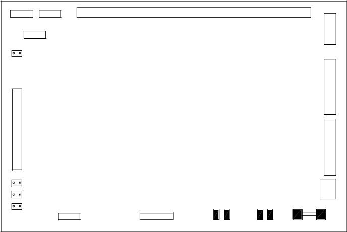
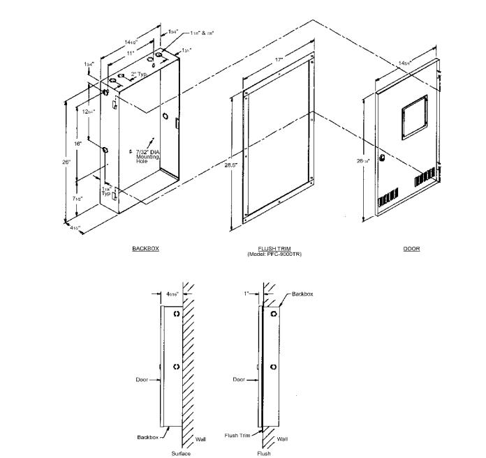
Cabinet Specifications
The cabinet is constructed of 18 gauge (0.048”) cold rolled steel. The cabinet is black in color with a red or white door and black trim. An optional white cabinet is also available. The door is hinged, keyed and removable. Combination ½” / ¾” knockouts are available on the top and side of the cabinet. The cabinet includes five stand-offs for mounting the main chassis and a ground terminal. The overall dimensions of the cabinet are 26” tall x 14 ½” wide x 4 ½” deep.
13

PFC-9000 • 5403535 • REV G • 9/08
Electrical Specifications
Input Power
The PFC-9000 operates on a nominal 120 or 240 VAC with a minimum and maximum line voltage of 102 VAC and 132 VAC or 204 VAC and 264 VAC respectively. A resettable 4-Amp fuse is installed on the primary side of the transformer-input power. The transformer is a 24-volt transformer that provides 12 Amps of power to the panel. For more detailed information on power consumption refer to the battery calculation sheet.
The fire alarm panel must be connected to a dedicated circuit and should be wired using 12 AWG wire through the side conduit entrance. The black (hot) must be connected to the line, the white to the neutral (N) and the green to the ground. An earth ground must also be connected to the cabinet.
Per the National Electrical Code, the fire alarm circuit breaker should be marked red and labeled.
Battery Backup Requirement
The PFC-9000 is capable of charging standby batteries from 17 to 40 amp-hours. The batteries should be sized according to the battery calculation performed that accounts for all standby currents and power requirements when the panel is in alarm.
Permanent installations require AC power and battery backup to be supplied to the panel. Failure to properly size batteries could result in the panel prematurely shutting down when there is a loss of AC power.
17 AH batteries are the minimum capacity batteries allowed in the PFC-9000 series. The installation of batteries with a capacity less than 17 AH will damage the batteries and panel.
When the panel communicates to a Central Station, a minimum of 24 hours of stand-by current and five minutes of alarm current is required. When communicating to a Remote Supervising Station, a minimum of 24 hours of battery stand-by is required followed by five minutes of alarm current.
The cabinet will house up to 18 amp-hour batteries; larger batteries will need to be housed in a separate cabinet.
A 20-amp fuse on the main board protects the battery circuit. If the panel is showing a trouble condition of missing batteries, and the batteries are connected and meter to the correct voltages, then the fuse should be replaced.
Connect AC power to panel followed by batteries. Observe polarity when connecting batteries. Failure to do so may result in damage to the batteries, battery leads, or panel.
14
PFC-9000 • 5403535 • REV G • 9/08
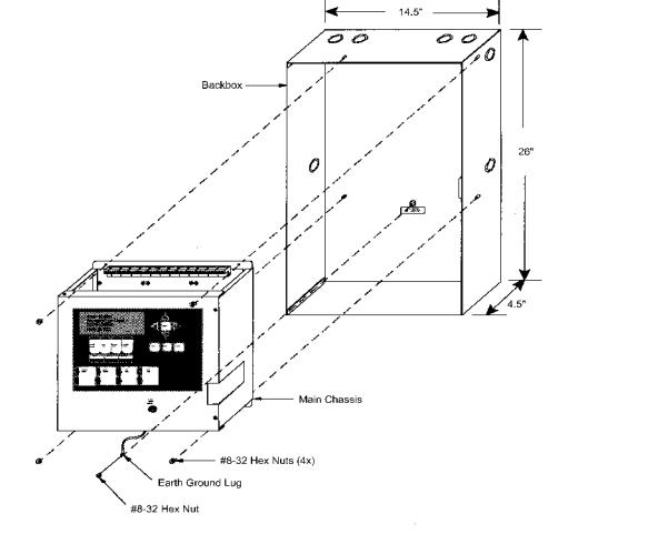
CHAPTER 3: CABINET INSTALLATION
Step 1 Remove Chassis from Cabinet
The chassis is included in every PFC-9000 series fire alarm panel when it leaves the factory. It is recommended that the chassis be removed from the cabinet before installing the cabinet to reduce the possibility of foreign debris being introduced on the circuit boards. The chassis is connected to the cabinet using five #8-32 hex nuts. The main body of the chassis connects in each of the four corners and the fifth nut connects to a ground terminal. The furthest right removable terminal block must be removed to install the top right nut.
Step 2 Install Cabinet
Install the cabinet in either a surface or flush mount orientation. Allow necessary clearance for all necessary field wiring. The PFC-9000 cabinet has knockouts located on the sides and top for bringing the wire to and from the panel. The different wiring should be isolated to prevent electrical noise and induced voltages. The wiring should be separated by the type of circuit: AC voltage input, notification circuits, signalling line circuit, telephone communication, annunciator communication and relays. Failure to do so could increase the chances of a false alarm.
Step 3 Power Connections
·Connect panel ground terminal to EARTH GROUND (cold water pipe)
·With the dedicated circuit breaker in the OFF position, connect the black (hot) to the line (L), the white to the neutral (N) and the green to the ground (G).
15

PFC-9000 • 5403535 • REV G • 9/08
CONNECT GREEN EARTH GROUND
WIRE TO MAIN MODULE PCB
MOUNTING SCREW
P10 |
P11 |
P12 |
P13 |
|
+ BAT - |
|
|
|
TO DEDICATED 120 VAC, 60 |
|
|
|
HZ BRANCH CIRCUIT |
|
|
RED |
240 |
120 N |
G |
|
|
|
|
TO 24 VDC |
|
|
|
BATTERY |
|
|
|
BLACK |
|
|
|
To prevent sparking, connect batteries after the systems main A.C. Power is turned on.
DWG# PFC-9000-3
Step 4 Initial System Checkout
Before Powering Up the Panel:
It is recommended that the PFC-9000 is powered up before any field wiring or modules are connected to it. The following directions will guide the user through the initial set-up and step by step process of the initial start-up.
1.To prevent sparking, do not connect the batteries first. Connect the batteries after powering the system from the main AC supply.
2.Check all Jumpers and Switches for proper setting (Refer to page 10)
3.Check the AC power wiring for proper connection
4.Check that the chassis is connected to EARTH GROUND (cold water pipe)
5.Make sure to close the front cover plate before powering the system from main AC supply
Step 5 Initial Power Up Procedure:
1.Turn on dedicated Circuit Breaker.
2.Once power is supplied to the panel, the “Trouble Queue” LED will light and the LCD will display “Initial system self checks in progress…” This will last between 30 and 90 seconds. The trouble buzzer will sound.
3.After completing the System Checkout procedures the “A.C. ON” green LED will light, the “Trouble Queue” LED will light, the buzzer will sound, and the LCD Display will display “System Restart, TRB Trouble 001 of 002…” (001 of 003 for the PFC-9100 series because the phone line voltage is not present). Press the “SYSTEM RESET” button to clear the first trouble.
4.Since the batteries are not connected, “Battery trouble active TRB 001 of 001” will be displayed on the LCD, and the trouble buzzer will sound intermittently and the Trouble Queue LED will flash.
5.Connect the batteries while observing correct polarity; the red wire is positive (+) and black wire is negative (-).
Connect the red wire to the positive terminal of battery #1 and the black wire to the negative terminal of battery #2. Use the short black jumper wire on the wiring harness to connect the negative terminal of battery #1 to the positive terminal of battery #2. By connecting the two 12 Volt batteries, a 24 Volt battery backup will be generated.
6.All indicators should extinguish except for normal power “A.C. ON” green LED, and the LCD should show a normal status condition. If the panel does not follow the preceding steps, please contact Potter Technical Support.
7.Power the panel down by removing the battery power and the main A.C. power.
16
PFC-9000 • 5403535 • REV G • 9/08
Chapter 4 annunciator installation
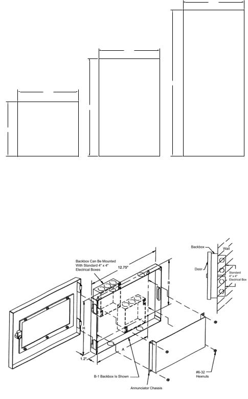
Annunciator Overview
The PFC-9000 may be connected in any order to three types of annunciators, liquid crystal display (LCD), light emitting diodes (LED’s) and graphic annunciation. A maximum of 272 points can be annunciated on the LED annunciator or graphic driver.
The annunciators must be mounted in a backbox and the number of needed LED’s will determine the backbox size. Sizes are available for one to three annunciators per backbox, and each annunciator occupies one space. The backbox must be mounted flush on the wall utilizing either one or two electrical boxes.
9.95
9.95
23.00
9.95
16.00
9.00
DWG# PFC-9000-5
The communication wiring must be two conductor twisted shielded cable from the panel or previous annunciator. A maximum of eight RA-LCD or RA-LED32 annunciators may be connected to a PFC-9000. In addition to the communication wire, the annunciators must be powered from the auxiliary power supply from the panel. The communcation wires and power wires must be in seperate cables.
Note: If an existing annunciator must be replaced, the program must be reloaded into the panel for the panel to communicate with the annunciator.
17

|
PFC-9000 • 5403535 • REV G • 9/08 |
|
RA-LCD OVERVIEW |
RS-485 |
POWER |
|
TERMINALS |
TERMINALS |
|
|
1 |
P1 |
P2 |
JW1
POTTER PFC-9000 FIRE ALARM
CONTROL PANEL NORMAL
CONDITION OCTOBER 2, 2001
ALARM |
SUPV. |
TROUBLE |
MONITOR |
QUEUE |
QUEUE |
QUEUE |
QUEUE |
SIGNAL |
GENERAL |
ACKNOWL- |
SILENCE |
ALARM |
EDGE |
SW1 |
24 VDC |
|
DIP SWITCH 8  SETTINGS
OFF ON
MENU
CANCEL
ENTER
INFO
A.C.
ON
PRE-
ALARM
GROUND
FAULT
FIRE |
SYSTEM |
LAMP |
DRILL |
RESET |
TEST |
DWG# PFC-9000-8B
Field Wiring Terminations
P1: LED Expansion Plug-Connects to the main annunciator chassis, or to the previous RA-LED48 P2: BDM Port: For factory use only.
RS-485 Connection: Communication cable connection from main panel SW1: Dip Switch Setting for Annunciator Address-Refer to page 21. 24 VDC: Power terminals from main panel
JW1: Jumper that is removed from RA-LCD annunciator unless it is the last RA-LCD in the series.
RA-LED 32 OVERVIEW (See field wiring Termination and Dip Switch information on page 20.)
P2 |
|
|
S |
S |
24 VDC |
24 VDC |
RS-485 |
RS-485 |
|
|
IN |
OUT |
IN |
OUT |
TEST/CONFIG |
COMMON |
|
|
|
MODE |
TROUBLE |
|
|
|
REMOTE |
A.C. |
|
|
|
FAILURE |
ON |
|
|
|
SYSTEM |
LAMP |
|
|
|
RESET |
TEST |
|
|
|
FIRE |
AUX. |
|
|
|
DRILL |
DISCON. |
|
|
|
ACKNOWL- |
BUZZER |
|
|
|
EDGE |
SILENCE |
|
|
|
GENERAL |
SIGNAL |
|
|
|
ALARM |
SILENCE |
|
|
|
|
DIP SWITCH |
|
DIP SWITCH |
|
|
SETTINGS |
|
SETTINGS |
|
|
|
|
ON |
|
|
ON |
1 |
SW1 |
8 |
OFF |
1 |
SW2 |
8 OFF |
P11
DWG# PFC-9000-8
18

PFC-9000 • 5403535 • REV G • 9/08
Field Wiring Terminations
P2: Connects to the first adder annunciator chassis.
24 VDC IN and OUT: In terminals for 24 VDC Aux. power from PFC-9000 and out terminals for power to next annunciator. RS485 IN and OUT: In terminals for RS-485 communication from PFC-9000 and out terminals for RS-485 to next annunciator. P11: Not used
SW1: See page 22 SW2: See page 22
Note: - RS-485 wiring must be twisted and shielded
-Separate cables must be used for power and the RS-485
-Maximum RS-485 wire distance is 8,000 ft of 18 Awg
- Power Requirements: LCD |
100ma Standby |
|
150ma Alarm |
LED-32 |
50ma Standby |
|
150ma Alarm |
The 24VDC field wiring must be of an appropriate gauge for the number of annunciators and the total wire length.
Annunciator Wiring Instructions
Step 1: Install Backbox
Step 2: Connect Field Wiring for First Annunciator
·Attach two conductor twisted shielded cable from RS-485 terminals on panel to RS-485 “IN” terminals on annunciator. The “S” terminal is for the cable shielding.
·Attach two conductor power cable from 24VDCAux Power terminals on main panel to 24VDC “IN” terminals on annunciator.
Do not use 4Wire Resettable Smoke power from main terminal.
·If not the last annunciator in the series, remove jumper JW1. (RA-LCD only)
·Assign address as described below.
Step 3: Attach Field Wiring to Subsequent Annunciators
·Attach two conductor twisted shielded cable from RS-485 “OUT” terminals on previous annunciator to RS-485 “IN” terminals on next annunciator. The “S” terminal is for the cable shielding.
·Attach two conductor power cable from 24VDC “OUT” Power terminals on previous annunciator to 24VDC “IN” terminals on next annunciator.
·If not the last annunciator in the series, remove jumper JW1.
·Assign address as described below.
·Continue until all annunciators are installed.
Accidentally connecting the 24 VDC Power connection to the Communication or vice versa will result in annunciator and/or panel damage!
AnnunciatorAddress Programming
Each annunciator must be addressed uniquely and sequentially in order for the panel to recognize the device. The addressing is completed using the dipswitches on the annunciator. Both the RA-LCD and the RA-LED32 utilizes the SW1 switch for the
address. The RA-LED32 has an additional set of dipswitches, SW2, for disabling the common features (i.e. System Reset, Signal Silence, etc.) as described below.
The RA-LCD is addressable by address, beginning with Address 33, whereas the RA-LED32 is addressed by the number the annunciator is in the system.
EXAMPLE: If a system had an RA-LCD and RA-LED32 annunciator the RA-LCD would be addressed 33 and the RA-LED32 would be addressed as 2 for being the second annunciator in the series. Use the following tables for Dip Switch Positions.
19
PFC-9000 • 5403535 • REV G • 9/08
RA-LCD Dip Switch Position
The “OFF” setting is the active setting for the RA-LCD annunciator and all of the dipswitches are binary. The following table indicates the dip switch position for each address for the RA-LCD, switches 7 and 8 are not used:
|
DIP S witc h |
|
|
|
|
|
|
|
|
|
|
|
|
|
|
|
|
|
|
Dis p la y An n u n c ia to r "Ad d re s s " |
|
|
|
|
|
|
|
|
|
|
|
|
|
|
|
|
|
|
||||||||||||||||||||||||
|
|
|
|
|
|
|
|
|
|
|
|
|
|
|
|
|
|
|
|
|
|
|
|
|
|
|
|
|
|
|
|
|
|
|
|
|
|
|
|
|
|
|
|
|
|
|
|
|
|
|
|
|
|
|
|
|
|
|
|
|
||
|
P o s itio n s |
|
33 |
|
|
34 |
|
|
35 |
|
|
36 |
|
|
37 |
|
|
38 |
|
|
39 |
|
40 |
|
|
41 |
|
|
42 |
|
|
43 |
|
|
44 |
|
|
45 |
|
|
|
46 |
|
|
47 |
|
||||||||||||||||
|
|
|
|
|
|
|
|
|
|
|
|
|
|
|
|
|
|
|
|
|
|
|
|
|
|
|
|
|
|
|
|
|
||||||||||||||||||||||||||||||
|
|
|
|
|
|
|
|
|
|
|
|
|
|
|
|
|
|
|
|
|
|
|
|
|
|
|
|
|
|
|
|
|
|
|
|
|
|
|
|
|
|
|
|
|
|
|
|
|
|
|
|
|
|
|
||||||||
|
S W1-1 |
|
OFF |
|
ON |
|
OFF |
|
|
ON |
|
OFF |
|
|
ON |
|
OFF |
|
ON |
|
|
OFF |
|
ON |
|
|
OFF |
|
ON |
|
|
OFF |
|
|
ON |
|
OFF |
|
||||||||||||||||||||||||
|
|
|
|
|
|
|
|
|
|
|
|
|
|
|
|
|
|
|
|
|
|
|
|
|
|
|
|
|
|
|
|
|
|
|
|
|
|
|
|
|
|
|
|
|
|
|
|
|
|
|
|
|
|
|
||||||||
|
S W1-2 |
|
ON |
|
OFF |
|
OFF |
|
|
ON |
|
|
ON |
|
OFF |
|
OFF |
|
ON |
|
|
ON |
|
|
OFF |
|
OFF |
|
ON |
|
|
ON |
|
|
OFF |
|
OFF |
|
||||||||||||||||||||||||
|
|
|
|
|
|
|
|
|
|
|
|
|
|
|
|
|
|
|
|
|
|
|
|
|
|
|
|
|
|
|
|
|
|
|
|
|
|
|
|
|
|
|
|
|
|
|
|
|
|
|
|
|
|
|
||||||||
|
S W1-3 |
|
ON |
|
|
ON |
|
|
ON |
|
OFF |
|
OFF |
|
OFF |
|
OFF |
|
ON |
|
|
ON |
|
|
ON |
|
|
ON |
|
|
OFF |
|
OFF |
|
OFF |
|
OFF |
|
||||||||||||||||||||||||
|
|
|
|
|
|
|
|
|
|
|
|
|
|
|
|
|
|
|
|
|
|
|
|
|
|
|
|
|
|
|
|
|
|
|
|
|
|
|
|
|
|
|
|
|
|
|
|
|
|
|
|
|
|
|
||||||||
|
S W1-4 |
|
ON |
|
|
ON |
|
|
ON |
|
|
ON |
|
|
ON |
|
|
ON |
|
|
ON |
|
OFF |
|
OFF |
|
OFF |
|
OFF |
|
OFF |
|
OFF |
|
OFF |
|
OFF |
|
||||||||||||||||||||||||
|
|
|
|
|
|
|
|
|
|
|
|
|
|
|
|
|
|
|
|
|
|
|
|
|
|
|
|
|
|
|
|
|
|
|
|
|
|
|
|
|
|
|
|
|
|
|
|
|
|
|
|
|
|
|
|
|
|
|
|
|
|
|
|
S W1-5 |
|
ON |
|
|
ON |
|
|
ON |
|
|
ON |
|
|
ON |
|
|
ON |
|
|
ON |
|
ON |
|
|
ON |
|
|
ON |
|
|
ON |
|
|
ON |
|
|
ON |
|
|
|
ON |
|
|
ON |
|
||||||||||||||||
|
|
|
|
|
|
|
|
|
|
|
|
|
|
|
|
|
|
|
|
|
|
|
|
|
|
|
|
|
|
|
|
|
|
|
|
|
|
|
|
|
|
|
|
|
|
|
|
|||||||||||||||
|
S W1-6 |
|
OFF |
OFF |
|
OFF |
|
OFF |
|
OFF |
|
OFF |
|
OFF |
|
OFF |
|
OFF |
|
OFF |
|
OFF |
|
OFF |
|
OFF |
|
OFF |
|
OFF |
|
|||||||||||||||||||||||||||||||
|
|
|
|
|
|
|
|
|
|
|
|
|
|
|
|
|
|
|
|
|
|
|
|
|
|
|
|
|
|
|
|
|
|
|
|
|
|
|
|
|
|
|
|
|
|
|
|
|
|
|
|
|||||||||||
|
|
|
|
|
|
|
|
|
|
|
|
|
|
|
|
|
|
|
|
|
|
|
|
|
|
|
|
|
|
|
|
|
|
|
|
|
|
|
|
|||||||||||||||||||||||
DIP S witc h |
|
|
|
|
|
|
|
|
|
|
|
|
|
|
|
|
|
|
|
Dis p la y An n u n c ia to r "Ad d re s s " |
|
|
|
|
|
|
|
|
|
|
|
|
|
|
|
|
|
|
||||||||||||||||||||||||
|
|
|
|
|
|
|
|
|
|
|
|
|
|
|
|
|
|
|
|
|
|
|
|
|
|
|
|
|
|
|
|
|
|
|
|
|
|
|
|
|
|
|
|
|
|
|
|
|
|
|
|
|
|
|
|
|
|
|
|
|
||
P o s itio n s |
|
48 |
|
49 |
|
|
50 |
|
|
51 |
|
|
52 |
|
|
53 |
|
|
54 |
|
|
55 |
|
|
56 |
|
|
57 |
|
|
58 |
|
|
59 |
|
|
60 |
|
|
61 |
|
|
62 |
|
63 |
|||||||||||||||||
|
|
|
|
|
|
|
|
|
|
|
|
|
|
|
|
|
|
|
|
|
|
|
|
|
|
|
|
|
|
|
||||||||||||||||||||||||||||||||
|
|
|
|
|
|
|
|
|
|
|
|
|
|
|
|
|
|
|
|
|
|
|
|
|
|
|
|
|
|
|
|
|
|
|
|
|
|
|
|
|
||||||||||||||||||||||
|
S W1-1 |
|
ON |
|
OFF |
|
|
ON |
|
OFF |
|
|
ON |
|
OFF |
|
|
ON |
|
OFF |
|
|
ON |
|
OFF |
|
|
ON |
|
OFF |
|
|
ON |
|
OFF |
|
|
ON |
|
OFF |
||||||||||||||||||||||
|
|
|
|
|
|
|
|
|
|
|
|
|
|
|
|
|
|
|
|
|
|
|
|
|
|
|
|
|
|
|
|
|
|
|
|
|
|
|
|
|||||||||||||||||||||||
|
S W1-2 |
|
ON |
|
ON |
|
OFF |
|
OFF |
|
|
ON |
|
|
ON |
|
OFF |
|
OFF |
|
|
ON |
|
|
ON |
|
OFF |
|
OFF |
|
|
ON |
|
|
ON |
|
OFF |
|
OFF |
|||||||||||||||||||||||
|
|
|
|
|
|
|
|
|
|
|
|
|
|
|
|
|
|
|
|
|
|
|
|
|
|
|
|
|
|
|
|
|
|
|
|
|
|
|
|
|||||||||||||||||||||||
|
S W1-3 |
|
ON |
|
ON |
|
|
ON |
|
|
ON |
|
OFF |
|
OFF |
|
OFF |
|
OFF |
|
|
ON |
|
|
ON |
|
|
ON |
|
|
ON |
|
OFF |
|
OFF |
|
OFF |
|
OFF |
|||||||||||||||||||||||
|
|
|
|
|
|
|
|
|
|
|
|
|
|
|
|
|
|
|
|
|
|
|
|
|
|
|
|
|
|
|
|
|
|
|
|
|
|
|
|
|||||||||||||||||||||||
|
S W1-4 |
|
ON |
|
ON |
|
|
ON |
|
|
ON |
|
|
ON |
|
|
ON |
|
|
ON |
|
|
ON |
|
OFF |
|
OFF |
|
OFF |
|
OFF |
|
OFF |
|
OFF |
|
OFF |
|
OFF |
|||||||||||||||||||||||
|
|
|
|
|
|
|
|
|
|
|
|
|
|
|
|
|
|
|
|
|
|
|
|
|
|
|
|
|
|
|
|
|
|
|||||||||||||||||||||||||||||
|
S W1-5 |
|
OFF |
|
OFF |
|
OFF |
|
OFF |
|
OFF |
|
OFF |
|
OFF |
|
OFF |
|
OFF |
|
OFF |
|
OFF |
|
OFF |
|
OFF |
|
OFF |
|
OFF |
|
OFF |
|||||||||||||||||||||||||||||
|
|
|
|
|
|
|
|
|
|
|
|
|
|
|
|
|
|
|
|
|
|
|
|
|
|
|
|
|
|
|
|
|
|
|||||||||||||||||||||||||||||
|
S W1-6 |
|
OFF |
|
OFF |
|
OFF |
|
OFF |
|
OFF |
|
OFF |
|
OFF |
|
OFF |
|
OFF |
|
OFF |
|
OFF |
|
OFF |
|
OFF |
|
OFF |
|
OFF |
|
OFF |
|||||||||||||||||||||||||||||
|
|
|
|
|
|
|
|
|
|
|
|
|
|
|
|
|
|
|
|
|
|
|
|
|
|
|
|
|
|
|
|
|
|
|
|
|
|
|
|
|
|
|
|
|
|
|
|
|
|
|
|
|
|
|
|
|
|
|
|
|
|
|
The RA-LCD has a continuity jumper (JW1) that is removed on all annunciators except the last one.
The RA-LED32 must be addressed as the number of annunciator as it is in the system. The table below is the switch setting necessary for addressing the annunciator.
The “ON” setting is active for the RA-LCD annunciator.
DIP S witc h |
|
|
|
|
RA-LED An n u n c ia to r "Ad d re s s " |
|
|
|
|
||||||
|
|
|
|
|
|
|
|
|
|
|
|
|
|
|
|
P o s itio n s |
1 |
2 |
3 |
4 |
5 |
6 |
7 |
8 |
9 |
10 |
11 |
12 |
13 |
14 |
15 |
|
|||||||||||||||
|
|
|
|
|
|
|
|
|
|
|
|
|
|
|
|
S W1-1(A0) |
ON |
OFF |
ON |
OFF |
ON |
OFF |
ON |
OFF |
ON |
OFF |
ON |
OFF |
ON |
OFF |
ON |
|
|
|
|
|
|
|
|
|
|
|
|
|
|
|
|
S W1-2(A1) |
OFF |
ON |
ON |
OFF |
OFF |
ON |
ON |
OFF |
OFF |
ON |
ON |
OFF |
OFF |
ON |
ON |
|
|
|
|
|
|
|
|
|
|
|
|
|
|
|
|
S W1-3(A2) |
OFF |
OFF |
OFF |
ON |
ON |
ON |
ON |
OFF |
OFF |
OFF |
OFF |
ON |
ON |
ON |
ON |
|
|
|
|
|
|
|
|
|
|
|
|
|
|
|
|
S W1-4(A3) |
OFF |
OFF |
OFF |
OFF |
OFF |
OFF |
OFF |
ON |
ON |
ON |
ON |
ON |
ON |
ON |
ON |
|
|
|
|
|
|
|
|
|
|
|
|
|
|
|
|
The SW2 is the switch that enables/disables the common push buttons of the RA-LED32. The following switches will disable the common features.
SW2-1 = |
Disable System Reset Button |
SW1-1 = |
Address A0 |
||
SW2-2 = |
Disable Fire Drill Button |
SW1-2 = |
Address A1 |
||
SW2-3 = |
Disable Acknowledge Button |
SW1-3 = |
AddressA2 |
||
SW2-4 = |
Disable General Alarm Button |
SW1-4 = |
AddressA3 |
||
SW2-5 |
= |
Not Used |
SW1-5 |
= Not Used |
|
SW2-6 |
= |
Disable Auxiliary Disconnect Button |
SW1-6 |
= Not Used |
|
SW2-7 |
= |
Not Used |
SW1-7 |
= Not Used |
|
SW2-8 |
= |
Disable Signal Silence Button |
SW1-8 |
= Not Used |
|
20
PFC-9000 • 5403535 • REV G • 9/08
RA-LED 48
An adder display may be added to provide additional LED’s to either the RA-LCD or the RA-LED32. The RA-LED48 is installed above the main annunciator in either the BB-2 or BB-3 back box. The RA-LED48 connects to the other annunciator via a ribbon cable on plug P1.
P2
ADDER ANNUNCIATOR BOARD
P1
P2 |
P3 |
RA-LCD OR RA-LED32
MAIN ANNUNCIATOR BOARD
DWG# PFC-9000-12
21
PFC-9000 • 5403535 • REV G • 9/08
PGD-32 and PGD-48 Graphic Drivers
The PGD-32 graphic driver provides the link between the PFC-9000 and large graphic annunciators. Other manufacturers supply the actual display, but the lights are illuminated using the graphic driver. The PGD-32 is essentially a large switch that turns on LED’s or lamps that are correlated to a specific input. In addition, the graphic driver provides outputs for the common indicators as well as the common controls. The PGD-32 has inputs for common control buttons and outputs for the common indicators and thirty-two configurable outputs for lamps or LED’s. The graphic driver requires a nominal 24 VDC to operate, 24 VDC for the lamp power and the RS-485 communication. A single PGD-32 will support up to 224 circuit display points using up to four of the PGD-48 expansion boards. Jumpers on the PGD-32 control all of the features including supervision of the outputs.
The system may be expanded to have a maximum of five PGD-48 connected to any one main annunciator. Terminal P1 on the expansion board will have a ribbon cable that will plug into P2 of the preceding board. The PGD-48 is an expansion of the main annunciator and therefore does not count as one of the eight annunciators.
The PGD-32 is connected to panel through the RS-485 annunciator output and is programmed essentially in the same way as the RA-LED32 LED annunciator. The PGD-32 is considered the same as an annunciator and therefore occupies one of the eightannunciator points. Each lamp point is correlated to an input and the panel activates the particular circuit when the input activates. In addition, the addressing for the graphic driver is the same as the RA-LED32 in that the driver is given an address in accordance with what number of annunciator in line it is. For further information, refer to the PGD-32 and PGD-48 Wiring and Installation Instruction manual included with the graphic drivers.
CHAPTER 5 Module Adder Circuit Cards
Overview
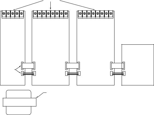
The circuit adder cards are attached directly to the PFC-9000 chassis using screws and stand-offs. The stand-offs are factory installed for the ease of adding modules in the field. The circuit adder cards must be installed from the right to the left due to the plug connection for power and communication. A few exceptions do exist. The UDACT-9100 must be installed in the far-left spot due to plug connections. Also, the loop adders must be installed in the far-right spot due to plug and power connections.
Note: Circuit adder cards must be installed in the PFC-9000 panel in the same order as they are loaded into the system configuration software.
ADDER MODULES
PROVISIONS FOR
PR 5000 OR
UDACT-9100
3 |
2 |
1 |
PFC-9000 CHASSIS
NOT USED ONP2 |
P1 |
P2 |
P1 |
P2 |
P6 |
UDACT-9100 |
|
|
|
|
|
OR PR 5000 P4 |
P3 |
P4 |
P3 |
P4 |
P8 |
TRANSFORMER
BEGIN BY ADDING MODULES
FROM THE RIGHT.
Wiring Diagram without Loop Adder
The PFC-9100 has the UDACT-9100 factory installed in the left adder location. If more than three cards are needed, contact Potter Technical Support.
22
PFC-9000 • 5403535 • REV G • 9/08
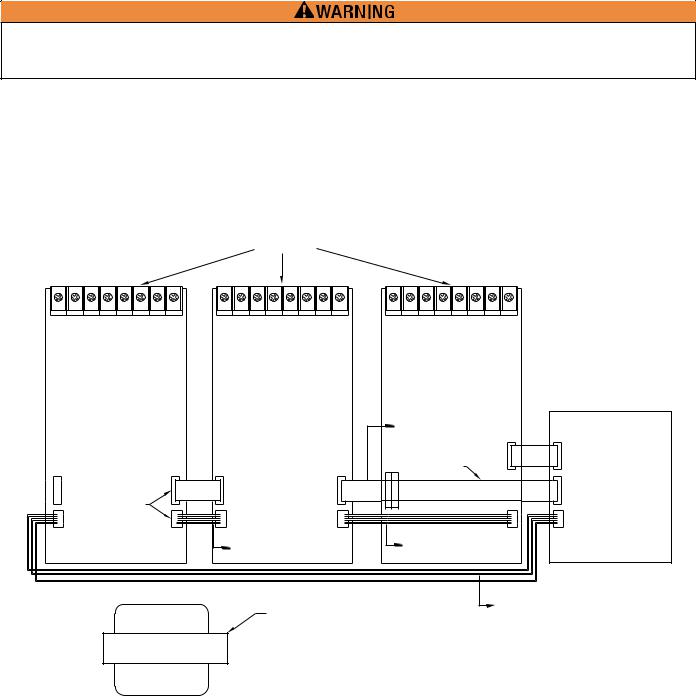
Care must be taken to ensure that the proper terminals and plugs are connected. Failure to observe plug keys and proper plug locations can result in circuit card and main panel damage. Make all connections from the circuit adder cards to the main panel with the panel powered down and batteries disconnected.
When a loop adder, either the SLA-127P or the DLA-254P, is installed in the PFC-9000 the wiring configuration must be such that each module receives power and the proper communication. The loop adder must be installed in the farthest most right spot and the ribbon cable must plug directly into P5 on the main chassis. If other boards are also being installed, they should be installed first starting with the middle slot. The long ribbon cable included with the loop adder must be plugged into P6 on the main board and connected to the ribbon cable on the first adder board other than the loop adder. In addition, the long power cable connects from P8 on the PFC-9000 to P3 on the last adder card to the left. The long power cable and ribbon cable are included with the SLA or DLA.
PROVISIONS FOR
PR 5000 OR
UDACT-9100
3
P1 NOT USED ON |
P2 |
UDACT-9100 |
|
P3 OR PR 5000 |
P4 |
ADDER MODULES
SLA-127P
OR
DLA-254P
2 |
|
1 |
|
|
|
|
ADD EXTENSION |
|
PFC-9000 CHASSIS |
|
|
CABLE TO ZA-9008 |
|
|
|
|
ROUTE UNDER BOARD |
P2 |
P5 |
|
|
|
|
|
P1 |
P2 |
ARM-9008 OR IDC-9004 PCB |
P6 |
|
P3 |
P4 |
|
P1 |
P8 |
SHORT 4-WIRE |
|
MEDIUM 4-WIRE |
|
|
|
|
|
||
POWER CABLE |
|
POWER CABLE |
|
|
|
|
|
LONG 4-WIRE |
|
TRANSFORMER |
|
POWER CABLE |
|
|
BEGIN BY ADDING MODULES
FROM THE RIGHT.
Wiring Diagram with Loop Adder
23

PFC-9000 • 5403535 • REV G • 9/08
SLA-127P Single Loop Intelligent Adder Card
The Single Loop Adder provides an additional 127 addressable points to the base 127 addressable points standard with the PFC9000. The addressable loop is fully analog/addressable and can be any combination of sensors and modules. Only one loop adder module, either the SLA-127P or the DLA-254P (Dual Loop Intelligent Adder Card) can be installed to a PFC-9000 system.
The SLA-127P mounts in the far right adder location in the PFC-9000 and connects directly to the main fire alarm board. The stand-offs are factory installed in the chassis and the SLA-127P screws directly to the stand-offs. Power down the system and connect the plugs to the main fire alarm panel before fastening the adder card to the panel chassis. The SLA-127P is Loop 2 in the Configuration Software.
The P2 ribbon cable from the adder card is connected to P5 on the main fire alarm panel. The yellow loop expansion sticker will have to be removed before connecting the loop adder to the main board. If additional adder cards will be installed, plug the long ribbon cable that comes with the DLA into P6 on the PFC-9000 board. This cable will connect to P2 on the next adder card to the left.The loop adder receives power from the main fire alarm control panel. If just a SLA 127P is added the cord will plug into the main board (P8). If Adder Modules are installed, a longer cable is used to connect P3 of the furthest left module to P8 of the 9000 chassis. P4 of the adder module next to the SLA-127P then connects to P1 of the Loop Adder.
All of the loops must be wired either Class A or Class B, the mixing of wire combination is not possible. If shielded cable is used as the loop conductor, only wire one leg to the “Shield” terminal on the loop adder board. As with the main panel, the terminals are marked for Class A and Class B wiring.
SLA-127P SINGLE LOOP CONTROLLER MODULE
LOOP A
B
A
CONNECTS TO P5 ON MAIN
FIRE ALARM BOARD
P2
POWER CABLE CONNECTS TO P8
ON MAIN FIRE ALARM BOARD
OR P3 OF ADDER MODULE.
DWG# PFC-9000-15
24
PFC-9000 • 5403535 • REV G • 9/08
DLA-254P Dual Loop Intelligent Adder Card
The Dual Loop Adder provides two additional loops with 127 addressable points per loop in addition to the base 127 addressable points standard with the PFC-9000. The addressable loops are fully analog/addressable and can be any combination of sensors and modules. Only one loop adder, either a SLA-127P or DLA-254P can be installed in a PFC-9000.
The DLA-254P mounts in the far right adder location in the PFC-9000 and connects directly to the main fire alarm board. The stand-offs are factory installed in the chassis and the DLA-254P screws directly to the stand-offs. Power down the system and connect the plugs to the main fire alarm panel before fastening the adder card to the panel chassis. The DLA-254P is Loop 2 and Loop 3 in the Configuration Software.
The ribbon cable from the panel is connected to P5 on the main fire alarm panel. The yellow loop expansion sticker will have to be removed before connecting the loop adder to the main board. If additional adder cards will be installed, plug the long ribbon cable that comes with the DLA into P6 on the PFC-9000 board. This cable will connect to P2 on the next adder card to the left. The loop adder receives power from the main fire alarm control panel. If just a DLA-254P is added the cord will plug into the main board (P8). If Adder Modules are installed, a longer cable is used to connect P3 of the furthest left module to P8 of the 9000 chassis. P4 of the adder module next to the DLA-254P then connects to P1 of the Loop Adder.
All of the loops must be wired either Class A or Class B, the mixing of wire combination is not possible. If shielded cable is used as the loop conductor, only wire one leg to the “Shield” terminal on the loop adder board. As with the main panel, the terminals are marked for Class A and Class B wiring.
DLA-254P DUAL LOOP CONTROLLER MODULE |
|
LOOP A |
LOOP B |
B |
B |
A |
A |
|
CONNECTS TO P5 ON MAIN |
|
FIRE ALARM BOARD |
P2
P1
POWER CABLE CONNECTS TO P8
ON MAIN FIRE ALARM BOARD
OR P3 OF ADDER MODULE
DWG# PFC-9000-16
25

PFC-9000 • 5403535 • REV G • 9/08
ZA-9008 Conventional Circuits Card
The ZA-9008 provides either eight Class B conventional circuits or four Class A conventional circuits in addition to the addresses on the loop. The zones may be selected as a number of different input types as allowed in the Configuration Software. Any of the conventional inputs may be correlated to any of the outputs. All field-wiring terminals are removeable for ease of wiring. The ZA9008 can be installed on top of the UDACT-9100 card in the left space, or in any available space from right to left.
The list for compatible devices is in Appendix C.
Failure to use tested and listed compatible powered devices may result in system not operating or false activations.
FIELD WIRING TERMINALS
P2 |
P4 |
JW4
JW3
JW2
JW1
P1 |
P3 |
JW5
DWG# PFC-9000-17
Jumpers |
|
JW1 |
Jumper installed for Class A (Style D) initiation of Circuits 1 & 2 |
JW2 |
Jumper installed for Class A (Style D) initiation of Circuits 3 & 4 |
JW3 |
Jumper installed for Class A (Style D) initiation of Circuits 5 & 6 |
JW4 |
Jumper installed for Class A (Style D) initiation of Circuits 7 & 8 |
JW5 |
Continuity Jumper installed only if device is the last circuit adder installed |
Plugs |
|
P1 |
Data cable for next circuit adder |
P2 |
Data cable attached to previous circuit adder or main fire alarm |
P3 |
Power connector to next circuit adder |
P4 |
Power connector to P8 of fire alarm board or previous circuit adder module |
26

PFC-9000 • 5403535 • REV G • 9/08
ZA-9008 Conventional Zone Wire Terminations
 3.9k Ω EOLR
TYPICAL CLASS B WIRING WITH END OF LINE RESISTOR
TYPICAL CLASS A WIRING. NOTE: EOLR IS NOT USED FOR CLASS A WIRING.
INI #1 |
INI #2 |
INI #3 |
INI #4 |
INI #5 |
INI #6 |
INI #7 |
INI #8 |
DWG# PFC-9000-38
Field Wiring Terminals
Note: All devices must be either wired ClassAor Class B. The combination of ClassAand B wiring is for demonstration purposes only.
WIRE SIZE |
MAXIMUM WIRING RUN |
|
|
(GAUGE) |
TO LAST DEVICE (ELR) |
|
|
|
|
|
|
(AWG) |
FEET |
METERS |
OHMS P ER 1,000FT |
|
|
|
|
22 |
2990 |
910 |
16.0 |
|
|
|
|
20 |
4760 |
1450 |
10.0 |
|
|
|
|
18 |
7560 |
2300 |
6.4 |
|
|
|
|
16 |
12000 |
3600 |
4.0 |
|
|
|
|
14 |
19000 |
5800 |
2.5 |
|
|
|
|
12 |
30400 |
9200 |
1.6 |
|
|
|
|
NOTE : MAXIMUM LOOP RESISTANCE SHOULD NOT EXCEED 100 OHMS
4-WIRE Smoke Wiring: The maximum allowable current is 0.2Amperes. The maximum allowed Voltage Drop is 1 Volt. Volt drop: Ed = It . R1
Ed = starting voltage, It = Total current, R1 = Resistance
-All jumpers are shipped installed over only 1 pin. If a class A wiring is chosen, the jumper for the corresponding circuit must be removed over both pins.
-If this is the last circuit adder card installed, move JW5 over both pins.
27
 Loading...