


PFC-4410RC
Manual #5403550 - Rev Q
11/12
St. Louis, MO
(866) 956-0988
www.pottersignal.com
PFC-4410RC
Releasing Panel for
Water and Agent
Extinguishing
Systems
Installation, Operation, and
Instruction Manual
(All specications subject to revision.)

2
PFC-4410RC • 5403550 • REV Q • 11/12
Potter Electric Signal Company, LLC
St. Louis, MO • (866) 956-0988
WARRANTY INFORMATION
The essential purpose of any sale or contract for sale of any of the products listed in the POTTER catalog or
price list is the furnishing of that product. It is expressly understood that in furnishing said product, POTTER
does not agree to insure the Purchaser against any losses the Purchaser may incur, even if resulting from the
malfunction of said product.
POTTER warrants that the equipment herein shall conform to said descriptions as to all afrmation of fact
and shall be free from defects of manufacture, labeling and packaging for a period of one (1), one and one
half (1.5), three (3), or ve (5) year'(s), depending on the product, from the invoice date to the original
purchaser, provided that representative samples are returned to POTTER for inspection. The product
warranty period is stated on the exterior of the product package. Upon a determination by POTTER that a
product is not as warranted, POTTER shall, at its exclusive option, replace or repair said defective product
or parts thereof at its own expense except that Purchaser shall pay all shipping, insurance and similar charges
incurred in connection with the replacement of the defective product or parts thereof. This Warranty is void
in the case of abuse, misuse, abnormal usage, faulty installation or repair by unauthorized persons, or if for
any other reason POTTER determines that said product is not operating properly as a result of causes other
than defective manufacture, labeling or packaging.
The Aforesaid Warranty Is Expressly Made In Lieu Of Any Other Warranties, Expressed Or Implied, It
Being Understood That All Such Other Warranties, Expressed Or Implied, Including The Warranties Of
Merchantability And Fitness For Particular Purpose Are Hereby Expressly Excluded. In No Event Shall
Potter Be Liable To Purchaser For Any Direct, Collateral, Incidental Or Consequential Damages In
Connection With Purchaser’s Use Of Any Of The Products Listed Herein, Or For Any Other Cause Whatsoever
Relating To The Said Products. Neither Potter Nor Its Representatives Shall Be Liable To The Purchaser
Or Anyone Else For Any Liability, Claim, Loss, Damage Or Expense Of Any Kind, Or Direct Collateral,
Incidental Or Consequential Damages Relative To Or Arising From Or Caused Directly Or Indirectly By Said
Products Or The Use Thereof Or Any Deciency, Defect Or Inadequacy Of The Said Products. It Is Expressly
Agreed That Purchaser’s Exclusive Remedy For Any Cause Of Action Relating To The Purchase And/or Use
Of Any Of The Products Listed Herein From Potter Shall Be For Damages, And Potter's Liability For Any And
All Losses Or Damages Resulting From Any Cause Whatsoever, Including Negligence, Or Other Fault, Shall
In No Event Exceed The Purchase Price Of The Product In Respect To Which The Claim Is Made, Or At The
Election Of Potter, The Restoration Or Replacement Or Repair Of Such Product.

3
PFC-4410RC • 5403550 • REV Q • 11/12
Co n t e n t s
Installation Precautions ................................................................................................................................................................ 5
General Description ..................................................................................................................................................................... 6
System Features ........................................................................................................................................................................... 6
Options ......................................................................................................................................................................................... 8
Ordering Information ..................................................................................................................................................................8
Specications ...............................................................................................................................................................................9
PFC-4410RC Visual Indicators .................................................................................................................................................... 9
LCD..............................................................................................................................................................................................9
PFC-4410RC Visual Indicators ................................................................................................................................................... 9
Control Buttons ............................................................................................................................................................................ 10
Circuit Parameters (All voltages regulated DC) - Initiating Device Circuits ..............................................................................10
Dedicated Supervisory Zone ........................................................................................................................................................ 10
Notication/Release Circuits ....................................................................................................................................................... 10
Low/Missing Battery ...................................................................................................................................................................11
Input Power .................................................................................................................................................................................. 11
Backup Power Requirements ....................................................................................................................................................... 12
Service Use ..................................................................................................................................................................................12
Listings and Approvals ................................................................................................................................................................ 12
Terminals ...................................................................................................................................................................................... 12
Relay Outputs ...............................................................................................................................................................................12
Annunciator Connection ..............................................................................................................................................................12
Optional Accessories ....................................................................................................................................................................12
Basic Operation ............................................................................................................................................................................13
Low Air Alarm .............................................................................................................................................................................13
Supervisory .................................................................................................................................................................................. 13
Trouble Conditions ......................................................................................................................................................................14
Notication Appliance/Releasing Circuits ...................................................................................................................................14
Loss or Reduction of AC Power ..................................................................................................................................................14
Low Battery Voltage .................................................................................................................................................................... 15
Loss Of Auxiliary Power Output .................................................................................................................................................15
To Silence the Buzzer (or outputs that have been described as trouble or supervisory bell)....................................................... 15
To Silence a Signaling Appliance ................................................................................................................................................ 15
To Reset an Alarm or Supervisory Condition ..............................................................................................................................15
To Reset A Trouble Condition ......................................................................................................................................................15
Lamp Test ..................................................................................................................................................................................... 16
Remote Annunciator Model RA-4410RC Operation ...................................................................................................................16
Test Procedure .............................................................................................................................................................................. 16
Programming Mode Instructions .................................................................................................................................................17
Panel Visual Display .................................................................................................................................................................... 17
PFC-4410RC Standard Program Information ..............................................................................................................................21
PFC-4410RC Custom Program Information for Water Based Extinguishing Systems ............................................................... 73
Installation Instructions ................................................................................................................................................................83
Wire checkout ..............................................................................................................................................................................83
Mounting Instructions .................................................................................................................................................................. 84
PFC-4410RC False Front Removal/Assembly Drawing .............................................................................................................84
Inactive Circuits ...........................................................................................................................................................................85
Operating Instructions Form ........................................................................................................................................................85
Battery Size Calculations ............................................................................................................................................................. 85
Battery Size Requirements And Maintenance .............................................................................................................................85
Current Requirements: Table 1 ....................................................................................................................................................86
Secondary Power Supply Requirements: Table 2 ........................................................................................................................86
Calculation Table .........................................................................................................................................................................86
Typical 2-Wire Detector Connection Drawing ............................................................................................................................ 87
Typical 4-Wire Wiring Diagram ..................................................................................................................................................87

4
PFC-4410RC • 5403550 • REV Q • 11/12
PFC-4410RC Connection Drawing .............................................................................................................................................88
2-Wire Smoke Detector Compatibility Data ................................................................................................................................89
Releasing Device Capability......................................................................................................................See Document 5403615
Wire Routing for PFC-4410RC ................................................................................................................................................... 90
NEC Section 760-54 .................................................................................................................................................................... 91
Connection Procedure for Battery Charging Current and Voltage ............................................................................................... 92
Installation Of Bezel For Semi-ush Installations ....................................................................................................................... 92
Connection Drawing for Central Station and Remote Station Operation .................................................................................... 93
Annex A: 4-Wire Smoke Detectors/Devices ...............................................................................................................................94
Annex B: Product Datasheets of Optional Equipment ................................................................................................................96
5
PFC-4410RC • 5403550 • REV Q • 11/12
The abort circuit will not abort the release or stop the predischarge timer activated by zones programmed as MANUAL
RELEASE. If it is desired to have the abort circuit stop the release activated from a Manual Release zone, program that zone as a
DETECTION zone instead.
High voltage electrocution hazard. Do not handle live AC wiring or work on the device while AC power is active.
This manual is designed to help with the specication, installation, and programming of the PFC-4410RC Release Panel. It is
imperative that this manual be completely read and understood before the installation or programming of the panel. Save this
manual for future reference.
Zones programmed as MANUAL RELEASE will override any cross zoning features. If it is desired to not have a manual station
override the cross zoning, program the zone as DETECTION and map accordingly.
Per ULC requirements; if this equipment is running on battery power only, it will shut off and cease to operate when the battery
voltage reaches approximatly 19-20 volts.
Fill in the name, address and telephone number of the servicing agency on the instruction sheet provided and
frame and place adjacent to control panel at eye level.
The following documentation shall be delivered to the owner or their representative upon nal acceptance of the system:
An owners manual and installation instructions covering all system equipment.
Wiring diagrams
A detailed description of the programming and operating sequence of the system
The detection and suppression system employing this release panel must be designed by people trained and competent in
the design and layout of re alarm and/or suppression systems for special hazard locations. The system shall be designed
and installed in accordance with all local and national codes and ordinances as well as the approval of the Authority Having
Jurisdiction. Only trained, qualied and competent individuals should install, program and/or service the PFC-4410RC.
Competent people would be aware of these warnings, limitations, and requirements.
Locate the panel and all system components in the following nominal environment:
* Temperature 32-120°F, Humidity 93% non-condensing.
* Verify that the wire sizes are adequate for all initiating, notication, and release circuits.
* Make certain the panel is properly grounded.
* Remove all electronic assemblies prior to any drilling, ling, reaming, or punching of the enclosure. When possible make all
cable entries from the sides, bottom, or rear of the cabinet. Verify that they will not interfere with the batteries or other components.
* The panel and system must be tested and maintained in accordance with all local and national codes and ordinances.
This is the safety alert system. It is used to alert you to potential personal injury hazards. Obey all
safety messages that follow this symbol to avoid possible injury or death.
Operating Instructions Form
Installation Precautions
6
PFC-4410RC • 5403550 • REV Q • 11/12
Design Guidelines
People trained in the design of special hazard systems shall determine the selection and placement of the initiating devices and
notication appliances connected to the PFC-4410RC. This responsible party shall also be familiar with the premises being protected.
The equipment shall be installed in accordance with the manufacturers instructions, the applicable version of NFPA 72 and all
local codes and ordinances. For systems employing cross zoning of two smoke detectors for the activation of the release circuit,
this can include but is not limited to the installation of photoelectric and ionization types of detectors on separate zones. One
of each type of detector on separate zones shall be installed in the coverage area selected for a single detector (not to exceed 0.7
times the linear spacing). The detectors would be installed in close proximity to each other.
The responsible party shall also determine the theory of operation regarding the programming sequence.
General Description
The Model PFC-4410RC is a listed and approved, microprocessor based re control/releasing panel. It is primarily designed for
use as a releasing panel for pre-action and deluge, water based extinguishing systems or for agent extinguishing systems. The
PFC-4410RC may also be used as a stand alone re control panel. This unit complies with NFPA-12, NFPA-12A, NFPA-13,
NFPA-15, NFPA -16, NFPA-17, NFPA-17A, NFPA-72, NFPA-750, NFPA-2001.
The PFC-4410RC complies with UL Standard 864, ULC S527-99, Canadian Electrical Code Part 1 C22.1., ULC S524, FM,
CSFM and NYMEA.
System Features
• Four Class B (Style B) Initiating zones. Each initiating zone can be set up for any of the following:
· Alarm Zones
· Detection alarm zone
· Waterow
· Linear Heat Detection (700 ohms per zone.)
· Manual Release
Fire Alarm System Limitations
Smoke detectors may not detect smoke when the smoke does not reach the detector. Such as smoke within walls, on the other
side of walls, on other oors, behind closed doors, explosions, etc. Smoke detectors will not operate if they are not properly
connected to the re/release panel. The detectors and bases must be UL listed as being compatible with the panel. The
detectors have a visible ashing light that indicates power is supplied to the detectors.
Notication appliances may not alert people if the people are not able to hear or see the appliances such as if they are in
separate areas of the building or room.
A re alarm/release panel will not operate without electrical power. The panel must have sufcient backup battery capability
to power the panel for a specied amount of time in the event of an AC power failure. The batteries and release panel shall be
tested and maintained in accordance with the testing and maintenance requirements of NFPA 72.
In order for emergency forces, (Fire departments, etc.), to respond to events associated with this panel, the panel must transmit
trouble, supervisory, and alarm signals to a monitoring facility either directly or through a main building re panel.
A problem in an audible or visual device may not be apparent when the panel is in a normal condition.
NOTICE TO ALL USERS, INSTALLERS, AHJ'S, AND OTHER INVOLVED PARTIES
This product incorporates eld programmable software. In order to comply with the requirements in the Standard for Control
Units and Accessories for Fire Alarm Systems, UL 864, certain programming features or options must be limited to specic
values or not used at all, as indicated below.
Program Feature or Option Permitted in UL 864 Possible Settings Settings Permitted in UL 864
NY Abort (Mode 3) No Mode 1, 2, 3, or 4 Modes 1 and 2
30-Second Abort (Mode 4) No Mode 1, 2, 3, or 4
Abort on Pre-action or Deluge
Systems
No
Supervisory, Tamper, Low air,
High Air, Abort
Supervisory, Tamper, Low
Air, High Air
7
PFC-4410RC • 5403550 • REV Q • 11/12
· Supervisory Zones
· Supervisory
· Tamper
· Low Air Supervisory
· High Air
· Low Air Alarm
NOTE: Only zones programmed as Detection, Waterow, Linear Heat, Manual Release, and Low Air
Alarm can be mapped to outputs programed as release.
· Remote Annunciator Output for connection to RA-4410RC:
· RS-485 communication, (2-wire shielded cable required)
· Regulated 24VDC annunciator power
· Two Supervisory Zones, Class B (Style B). This zone can be set up for any of the following:
· Supervisory
· Tamper
· Low Air Supervisory
· High Air
· * Abort (Supervisory zone 1 only)
NOTE: * Abort on a water-based extinguishing system is not a UL Listed function.
· Four Class B (Style Y) Output circuits. Each output can be set up for any of the following:
· Notication Appliance circuit, (First or Second alarm notication in chemical extinguishing mode)
· Releasing circuit
· Pulse Releasing circuit (called eAEROSOL, 1/16th sec on 15/16th sec off. Chemical mode only, will cycle 200
times before turning off)
· Supervisory Bell circuit
· Trouble Bell circuit
· One Abort Circuit (Available in Chemical Mode only) Programmable for four different operating modes
· ULI – Stops the pre-discharge timer at 10 seconds
· IRI – Abort must be activated before the second alarm is received
· NYC (not UL listed) A one time operation that adds 90 seconds to the remaining predischarge time
· * 30 Second Abort (stops or reverts the pre-discharge timer at 30 seconds)
NOTE: * Not a UL Listed function
· Fifteen Standard Programs for water based systems or custom program capability
· Nine Standard Programs for Chemical based systems or custom program capability
· User selectable between Water Based or Chemical Extinguishing
· Releasing Zones can be set up for either normal or cross zoning operation
· Discharge time is user selectable for either 7, 8, 9, 10, 20 minutes or continuous in the custom program
· All circuits inherently power limited per NEC 760 and UL 864 Section 14.4
· Initiating Circuit Disable feature
· Output Disable feature
· One-Man Walktest feature with automatic 30 minute restoration and releasing circuit disable
· Class B (Style B) Abort circuit available in Chemical mode. Three Abort modes available
· Pre-Discharge timer from 0-60 seconds available in Chemical mode only
· Manual Release 0-30 seconds predischarge timer in Chemical Mode only
· Notication Appliance Circuits can be programmed to operate upon 1
st
or 2
nd
alarm in Chemical Mode for pre-discharge
signal
· Diagnostic Indicators
Abort does not function and has no effect on panel operation
from zones programmed as MANUAL RELEASE.
An eAEROSOL output shall only be used with Aerosol
Generators (listed on page 90). Using a standard releasing
circuit for an Aerosol Generator can prevent the Aerosol
agent from being released.

8
PFC-4410RC • 5403550 • REV Q • 11/12
· Signal Silence button
· Buzzer Silence button
· Manual event scroll buttons
· Automatic resound of silenced trouble signals after 24 hours
· Built-in Trouble buzzer
· Common Contacts for Alarm/Trouble/Supervisory/Waterow
· 32 Character Liquid Crystal Display (LCD)
· 34 LED display
· User Generated Banner Message
· User Generated Zone Labeling
· 24 or 90 hour Battery Standby available (Where required by FM and Others)
· 24 Hour Clock
· Password Protection
· Remote annunciator output
· 4-Wire resettable smoke detector power
Options See Appendix B of the manual for product data sheets.
1. CAM - Module to convert one Class B Indicating Appliance Circuit to one Class A circuit.
2. CA2Z - Module to convert two Class B Initiating Device Circuits to two Class A circuits.
3. ARM-1 - Module to provide non-supervised 4PDT Relay designed to be activated by 24VDC Indicating and/or Releasing,
polarity reversing circuits.
4. ARM-2 - Module to provide two Form C contacts activated by Indicating or Releasing, polarity reversing circuits.
5. ARM-44 - Module to provide 8 Form C contacts activated by corresponding initiating zones and outputs. Contact
manufacture for data sheet 5401202.
6. RA-4410RC – Remote annunciator provides 34 LED’s for each zone in alarm supervisory or trouble, each output activated
or in trouble, AC power, Power trouble, System trouble, Ground fault, Supervisory, Supervisory trouble, Alarm, Alarm
silence and Pre-discharge/Discharging. The annunciator also has a lamp test switch. Contact manufacture for data sheet
5401175.
7. Abort switch. Contact manufacture for data sheet 5401136.
8. RCDS-1 - Releasing Circuit Disable Switch Contact manufacture for data sheet 5401214.
Ordering Information
Model No. Description Stock No.
RA-4410RC Remote annunciator 3006400
BB-RA-44R Surface mount back box for RA-4410RC 3006401
EOLP-R End of Line Plate f/Resistor 3002182
EOLP-D End of Line Plate f/Diode Assy 3002181
P32-1T Manual release station 1000447
Abort Switch 3001000
PFC-TW Bezel for semi-ush mounting (white) 5090157
PFC-TR Bezel for semi-ush mounting (red) 5090155
BT80 Battery, for 24 hour standby, 12V, 8.0AH (2 req’d) 5130084
BT120 Battery, for 60-90 hour standby, 12V, 12.0AH (2 req’d) 5130090
CA2Z 2-Zone Class A initiating module 3006013
CAM Class A indicating circuit module 3005300
ARM-1 Auxiliary Relay Module 4 Pole 3004726
ARM-2 Auxiliary Relay Module 3004725
ARM-44 8 Relay Module 3006221
RCDS-1 Releasing Circuit Disable Switch 3001002
Spare or Replacement Parts
EOL Resistor 5080593
EOL Resistor and Diode Assembly for releasing circuit 3005012
EOL Resistor with 6" wire leads 3005013
eMatch Protection Assembly for eAEROSOL circuit 3005014
Main Circuit Board Module 3006230
This equipment generates, uses, and can radiate radio frequency energy and if not installed and used in accordance with the instruction manual, may cause interference
to radio communications. It has been tested and found to comply with the limits for a Class A computing device pursuant to Subpart J of Part 15 of FCC Rules which
are designed to provide reasonable protection against such interference when operated in a commercial environment. Operation of this equipment in a residential area
is likely to cause interference in which case the user at his own expense will be required to take whatever measures may be required to correct the interference.

9
PFC-4410RC • 5403550 • REV Q • 11/12
Specications
PFC-4410RC
Type - 18 gauge sheet steel with hinged, removable, locked door
Size - 18 1/2" x 14 1/4" x 4 3/4"
Finish - Off-white or red cabinet with red on black logo.
Knockouts - 1/2" and 3/4", one of each on left side, two 3/4" and one 1/2" on right side, four 1/2", two 3/4" on top, and two 1/2"
and one 3/4" on the back
Option - Bezel for semi-ush mounting
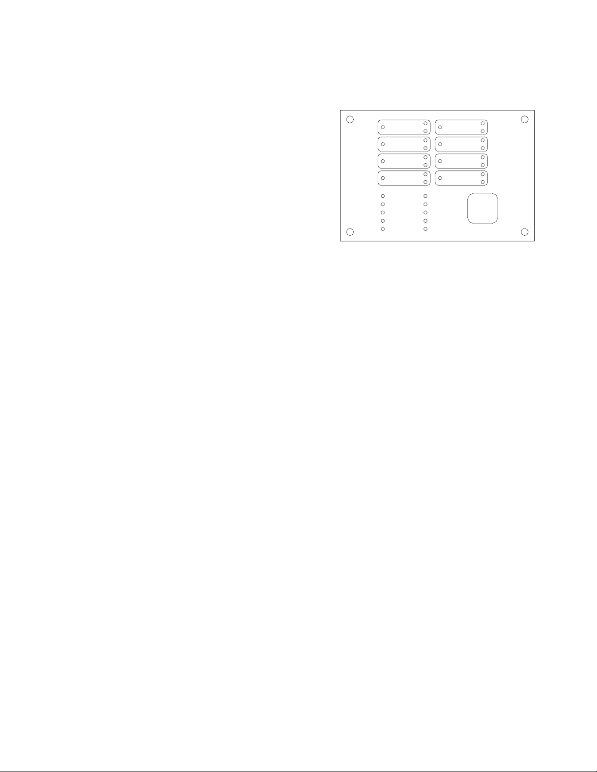
PFC-4410RC Visual Indicators
LED Indicators (red = alarm)
32 Character Alpha-Numeric Liquid Crystal Display (LCD)
LCD
A 2 line 32 character alpha-numeric liquid crystal display shows the condition, status and circuit for all
Alarm, Supervisory and Trouble conditions.
CONDITION STATUS CIRCUIT
Alarm Silenced <user Dened Message> (Up To 10 Characters)
Trouble Disabled Output #1
Supervisory Acknowledged Output #2
Tamper Output #3
Low Air Output #4
High Air Battery
Aborted A.C.
Pre-discharging Supervisory
Releasing Zone #1
Released Zone #2
Zone #3
Zone #4
Ground
PFC-4410RC Visual Indicators
In accordance with ULC S527-99 option B:
LED Annunciator Module
Red LED’s: Initiating Device Circuits Active (4),
Notication/Release Circuits Active (4)
Common Alarm (1)
Green LED: AC Power
Yellow LED’s: Initiating Device Circuits Troubles (4),
Output Circuits Troubles (4)
Supervisory Initiating Zone (4)
Supervisory Bell Output Active (4)
(1) each: Supervisory 1, Supervisory 2, Power Trouble, Supervisory Trouble, System Trouble, Ground Fault,
Pre-Discharge/Discharging, Alarm Silenced
CONDITION STATUS LED State
Trouble Non-Silenced Flashing
Trouble Silenced Steady ON
Alarm Non-Silenced Flashing
Alarm Silenced Steady ON
Supervisory Non-Silenced Flashing
Supervisory Silenced Steady ON
Pre-discharge Flashing
Discharging Steady ON

10
PFC-4410RC • 5403550 • REV Q • 11/12
Control Buttons
• Signal Silence - Momentary, silences signaling circuits, (except those activated by zones programmed as WATERFLOW)
• System Reset - Momentary, resets all alarm circuits if condition has been corrected, removes power from initiating device
circuits.
• Scroll Up - Scrolls LCD display to most recent events
• Scroll Down - Scrolls LCD display to previous events
NOTE: Buzzer silence is accomplished by scrolling through all events.
Circuit Parameters (All voltages regulated DC) - Initiating Device Circuits
Initiating Device Zones: For connection of dry contact initiating devices and compatible 2 wire smoke detectors. (All values nominal)
• 4 Class B, Style B (Class A Style D module available)
• Power limited, current limited to protect 2 wire smoke detectors
• Maximum 2 wire 24VDC smoke detector load per zone - 2.5 mA (Use only detectors that are listed in compatibility list.)
• Maximum Line resistance - 100 ohms (Except linear heat detection cable, 700 ohms per zone)
• End-of-Line Resistance - 5.1K ohm
• Normal standby current - approximately 4.0 mA
• Standby voltage - 25VDC maximum, 13.4 minimum
• Maximum short circuit current - approximately 36mA
• Maximum Impedance for Alarm - 1400 ohms
• Normal supervisory current - approximately 4mA
• Low current trouble activation - approximately 3.3mA
• Alarm activation current - approximately 10mA
• Ripple voltage - .4VDC
• Maximum operating voltage range: 22.5 - 25.9VDC
• Frequency - continuous
Dedicated Supervisory Zone
• For dry contact supervisory devices such as tamper, low air, or high air switches
• 2 Class B Style B circuit, latching
• Power limited, current limited
• End-of-Line resistance - 5.1K ohms
• Ripple Voltage - .1VDC
• Frequency - continuous
• Maximum voltage - 25VDC
• Maximum short circuit current - approximately 36mA
• Maximum line resistance - 100 ohms
• Normal supervisory current - approximately 4mA
• Low current trouble activation - approximately 3.3mA
• Supervisory current condition - approximately 10mA
Notication/Release Circuits
The indicating circuits of the PFC-4410RC are Non-coded. This allows the use of visual and audible appliances on the same
circuit. If temporal notication appliances are required for evacuation, selectable tone appliances such as the AMSECO H24WR
horn or SH24W Series strobe/horns or a temporal module such as AMSECO TMP1-3A or equivalents shall be used.
The notication outputs do not provide synchronization. See table for sync options and devices on page 89. The notication ap-
pliances shall be compatible with the sync module selected. The sync' module shall be installed as per manufacturers instructions.
Synchronization is limited to only one circuit and not between circuits. Systems intended for the release of Halon 1301 as de-
scribed in NFPA 12A, or clean agents as described in NFPA 2001, shall have provision for a pre-discharge notication circuit. If
the signal is required to be separate and/or distinct from the evacuation signal, two notication circuits are required. One shall be
programmed as FIRST ALARM. It will provide a steady output upon activation of any initiating zone programmed as an alarm
zone. This is the evacuation signal. If a temporal signal is required, notication appliances such as AMSECO model H24WR or
others that can produce a temporal tone shall be used. This allows the use of strobes and horns on the same circuit. The other no-
tication circuit shall be programmed as SECOND ALARM. It will provide a steady output upon activation of a second initiating
zone programmed as an alarm zone. This is when the pre-discharge timer would start and would be the pre-discharge signal. If a
temporal or other type of signal is required, notication appliances such as AMSECO model H24WR or equivalent shall be used.
This allows the use of strobes and horns on the same circuit. If a separate signal for discharge were required, a third notication
11
PFC-4410RC • 5403550 • REV Q • 11/12
circuit would be used that would be programmed to operate whenever the release circuit is activated. Equivalent sync modules
are shown on page 89.
Zones programmed as MANUAL RELEASE will activate outputs programmed as SECOND ALARM, even if the MANUAL
RELEASE zone is the rst alarm zone activated. SECOND ALARM is intended to be used as a pre-discharge signal for cross
zone applications. Refer to page 50 for a complete description of rst and second alarm requirements and operation.
• 4 Class B Style Y (Class A Style Z module available for notication)
• Reverse polarity upon activation
• Power limited, Current limited
• Outputs identied as Release are Special Application. All other outputs are Regulated 24 VDC, rated 1 Amp each, 2.5 Amps
total for all 4 circuits.
• End-of-Line-Resistor - 5.1k ohms
• Frequency - continuous
• Maximum voltage - 27VDC
• Ripple voltage - .3VDC
• Maximum impedance: 3 divided by NAC current draw
• Maximum resistance for outputs programmed as RELEASING:
1 divided by the current draw of the solenoid when activated
• Normal standby supervisory current - approximately .38mA
• Low current trouble activation - .11mA
• High current trouble activation - .63mA
Release Abort Circuit
• Available chemical mode only
• 1 momentary non-latching Class B Style B circuit
• Power limited, current limited
• Maximum loop resistance - 100 ohms
• End-of-Line-resistance - 5.1k ohms
• Frequency - continuous
• Normal supervisory current - approximately 4mA
• Low current trouble activation - approximately 3.3mA
• Abort current condition - approximately 10mA
• Maximum voltage - 23VDC
NOTE: Mode 3 is not UL Listed
Mode 1 – (ULI) Activation of the abort circuit stops the pre-discharge timer at 10 seconds. If there is less than 10 seconds
remaining, the time goes back to 10 seconds. Releasing the abort switch starts the timer at 10 seconds.
Mode 2 – (IRI) Operates the same as the ULI mode except the abort circuit only functions if the abort button is pressed before the
second alarm is received by the panel. The panel must be programmed for cross zoning for the IRI mode to function.
Mode 3 – (NYC) This mode is not UL listed. Activation of the abort circuit during the pre-discharge countdown adds 90 seconds
to the original pre-discharge time. This is a one-time feature. Repeated pressing of the abort button has no effect. The
pre-discharge timer resumes when the abort button is released.
Mode 4 – (30-Second Abort) This mode is not UL listed. Activation of the abort circuit stops the pre-discharge timer at 30
seconds. If there is elss than 30 seconds remaining, the timer goes back to 30 seconds. Releasing the abort switch starts
the timer at 30 seconds.
Low/Missing Battery
Causes battery and system trouble if battery falls below 22 volts. Battery circuit is fused and reverse polarity
protection is provided.
Input Power
• Universal Input 120VAC, (60 Hz, 165VA) or 220VAC, (50/60 Hz, 185VA) 15 Amp Branch Line over current
protection required
• AC Power indicator on LED annunciator module goes off on AC power loss (supervised)
• System trouble is also generated if voltage drops below 102V
• Supervised
Zones programmed as Manual Release cannot be aborted. If it is necessary to abort a manual station zone, program that zone as
Detection.
If the pre-discharge timer is set at 0 the abort circuit will not stop the release circuit.
NFPA 12 prohibits the use of abort circuits on Suppression Systems employing carbon dioxide.

12
PFC-4410RC • 5403550 • REV Q • 11/12
Backup Power Requirements
• PFC-4410RC - Standby 121 mA, alarm 274 mA at 24VDC, supervised
Service Use
NFPA 12 – Carbon Dioxide systems
NFPA 12A – Halon 1301 re systems
NFPA 13 - Automatic Sprinkler
NFPA 15 - Water Spray Fixed System
NFPA 16 - Foam Water Sprinkler and Foam Water Spray
NFPA 17 - Dry Chemical
NFPA 17A - Wet Chemical
NFPA 72 - National Fire Alarm Code
• Local
• Remote Station (protected premise unit)
• Central Station (protected premise unit)
NFPA 750 - Water Mist
NFPA 2001 - Clean Agent Fire Extinguishing System
Listings and Approvals
PFC-4410RC - UL Standard 864, ULC Standard S527, FM, CSFM, NYMEA and CE Marked.
Terminals
• All terminals capable of #22 - #14 AWG wire
• All terminations have transient protection
• All four initiating device circuit terminals capable of handling linear heat detection.
Relay Outputs
• Common system alarm contacts SPDT rated 3 Amps, 30VDC resistive
• Common supervisory contacts SPST, N.O. rated 3 Amps, 30VDC resistive
• Common system trouble contacts SPDT rated 3 Amps, 30VDC resistive
• Common waterow contacts, SPST, N.O. rated 3 Amps, 30VDC resistive
• Circuits connected to relays should be connected within the same room\
Auxiliary Power
• Auxiliary Power - 24VDC Special Application. Rated 200 mA max. Power limited, current limited, non-supervised
• Re-settable for 4-wire smoke detectors, see Annex A.
Annunciator Connection
• Auxiliary Power - 24VDC regulated. Rated 200 mA max. Power limited, current limited, supervised for RA-4410RC Annunciator
• RS-485 For connection to RA-4410RC remote annunciator
• Maximum 2000' with 22 AWG, 4000' with 20 AWG wire
Optional Accessories
CA2Z MODULE (Class A initiating device circuit):
Converts two Class B initiating device circuits to two Class A circuits.
CAM Module (Class A Notication Appliance Circuit):
Converts indicating appliance circuit from Class B to Class A. One model CAM (Class A Module) is required
for each circuit. (Do not use this on an output programmed as “Trouble Bell”.)
ARM-1/ARM-2 Module (Auxiliary Relay Module)
Activated by 24VDC Indicating and/or Releasing, polarity reversing circuits. The module provides a non-supervised DPDT Relay
that can be used for fan shutdown, door release, elevator recall, etc.
RA-4410RC (Remote Annunciator)
Connects to RS-485 & 24VDC terminals. Provides 34 LED’s for each zone in alarm supervisory, or trouble, each output activated
or in trouble, AC power, Power trouble, System trouble, Ground fault, Supervisory, Supervisory trouble, Alarm, Alarm silence and
Pre-discharge/Discharging.
13
PFC-4410RC • 5403550 • REV Q • 11/12
The annunciator also has a lamp test switch.
ARM-44 (Relay Module) - Relay installs in a cabinet and provides 8 relays. 4 relays mapped to inputs and 4 relays mapped to the
outputs in a 1 to 1 relationship selectable selectable disable switch.
RCDS-1 (Release Circuit Disconnect Switch)
Provides physical means of disconnecting release circuits in compliance with NFPA 72, 2007, 6.12.5.2.
Basic Operation
In addition to the following events, the panel also provides an output via the RS-485 terminals to the RA-4410RC remote
annunciator to light the appropriate indicators. See remote annunciator operations, page 15.
Initiating Device Circuits Alarm Condition:
An increase of current on any alarm initiating device circuit to approximately 10 mA or greater will result in the following:
ALARM, (Except zones programmed as LOW AIR ALARM):
1. Activation of the alarm relay contacts.
2. Activation of the output circuit(s) which are mapped to the initiating device circuit(s). Providing all zone(s)
necessary for the activation of those circuits is in alarm
3. “ALARM” and zone # displayed on LCD.
4. “PRE-DISCHARGE” displayed on LCD if zone(s) in alarm activated pre-discharge timer (In chemical mode only).
5. Activation of red ZONE indicator(s) on LED display for the initiating device circuit(s).
6. Activation of red ALARM indicator on LED display.
7. Activation of red OUTPUT indicator(s) on LED display module for the output circuit(s) which are mapped to the
initiating device circuit(s).
8. Activation of ashing red PRE-DISCHARGE indicator on LED display if in chemical mode and pre-discharge timer
was activated by zone(s) in alarm. Providing all zone(s) necessary for the activation of those circuits is in alarm.
Low Air Alarm
1. Operation of supervisory relay contacts and local buzzer.
2. Activation of the notication appliance circuit(s) or releasing circuit(s) which are mapped to the initiating device
circuit(s). Providing all zone(s) necessary for the activation of those circuits is in alarm.
3. LOW AIR ALARM and <CIRCUIT #> displayed on LCD.
4. Activation of yellow ZONE indicator on LED annunciator module for the initiating device circuit.
5. Activation of yellow ZONE indicator(s) on LED annunciator module for the initiating device circuit(s) described as
“LOW AIR ALARM”.
6. Activation of yellow OUTPUT indicator(s) on LED annunciator module for the output circuit(s) which are mapped to
the zone. Providing all zone(s) necessary for the activation of those circuits is in alarm.
7. Activation of the amber supervisory LED in a ashing mode. NOTE: The supervisory LED will continue to ash
until all events in the SUPERVISORY queue are viewed. This is accomplished by scrolling through all of the events by
use of the scroll up and scroll down buttons. The LED will go steady after all alarm events have been viewed.
Supervisory
An increase of current to approximately 8 mA or greater on the supervisory initiating device circuit(s) or disabling an output
programmed as realeasing will result in the following:
1. Operation of supervisory relay contacts and local buzzer.
2. Operation of any output circuits that have been described as SUPERVISORY BELL.
3. “SUPERVISORY”, “TAMPER”, “LOW AIR”, or “HIGH AIR” and <CIRCUIT> displayed on LCD.
4. Activation of yellow SUPERVISORY indicator on LED display.
5. Activation of yellow ZONE indicator(s) on LED display for the initiating device circuit(s) described as
“SUPERVISORY”, “TAMPER”, “LOW AIR SUPERVISORY”, or “HIGH AIR”.
6. Activation of yellow OUTPUT indicator(s) on LED display for the Notication appliance circuit(s)
described as SUPERVISORY BELL.
7. Activation of the amber SUPERVISORY LED in a ashing modes well as the corresponding zone LED. NOTE: The
SUPERVISORY LED will continue to ash until all events in the SUPERVISORY queue are viewed. This is accomplished by
When in CHEMICAL EXTINGUISHING mode, the release circuit(s), are not activated until the pre-discharge timer expires,
if a pre-discharge time was programmed. The predischarge time defaults to 30 seconds for Manual Release and 60 seconds for
all other alarm tones.
14
PFC-4410RC • 5403550 • REV Q • 11/12
scrolling through all of the events by use of the scroll up and scroll down buttons. The LED will go steady after all supervisory
events have been viewed.
Trouble Conditions
In custom program mode, failure to map at least 1 zone to every output or only mapping 1 zone to a release output programmed as
cross zoned will cause a system trouble. The display will read: TROUBLE NO OUTPUTS.
Initiating Device Circuits
A decrease of current to approximately 3.3 mA or programming the zone as disabled on any initiating device
circuit will result in the following:
1. Activation of trouble relay contacts, trouble LED and local buzzer.
2. Operation of any output circuits which have been described as TROUBLE BELL.
3. “TROUBLE” and <CIRCUIT> displayed on LCD.
4. Activation of yellow ZONE indicator(s) on LED annunciator module for the initiating device circuit(s).
5. Activation of yellow SYSTEM TROUBLE indicator on LED annunciator module.
6. Activation of yellow OUTPUT indicator(s) on LED annunciator module of any output circuit(s) which have been
described as TROUBLE BELL.
7. Activation of the amber TROUBLE LED in a ashing mode. NOTE: The TROUBLE LED will continue to ash until
all events in the TROUBLE queue are viewed. This is accomplished by scrolling through all of the events by use of
the scroll up and scroll down buttons. The LED will go steady after all trouble events have been viewed.
NOTE: When the circuits are operated in the Class A mode any trouble condition will require manual operation of the reset switch
to restore the panel to normal after the fault has been removed.
A complete loss of power will result in the transfer of the common system trouble relay contacts.
Notication Appliance/Releasing Circuits
An increase of current to approximately 0.63 mA or a decrease in current to approximately 0.11 mA on any output circuit or
connecting an indicating appliance backwards, or disabling an output will result in the following:
1. Activation of trouble relay contacts, trouble LED and local buzzer.
2. Operation of any output circuits which have been described as TROUBLE BELL. If this output is in trouble, a
TROUBLE BELL on this output may not function correctly, depending on the type of trouble.
3. “TROUBLE” and “OUTPUT #” <CIRCUIT NO.> displayed on LCD.
4. Activation of yellow OUTPUT indicator(s) on LED display for the notication appliance(s).
5. Activation of yellow SYSTEM TROUBLE indicator on LED display.
6. Activation of yellow OUTPUT indicator(s) on LED display of any output circuit(s) which have been described as
TROUBLE BELL.
NOTE: A current in excess of 1.4 Amps, when the panel is in the alarm condition, will result in that output being disabled and a
trouble as described above.
Ground Fault
A short between any circuit and earth ground will result in the following:
1. Activation of trouble relay contacts, trouble LED in a ashing mode, and local buzzer.
2. Operation of any output circuits which have been described as TROUBLE BELL.
3. “TROUBLE” and “GROUND” displayed on LCD.
4. Activation of the amber TROUBLE LED in a ashing mode. NOTE: The TROUBLE LED will continue to ash
until all events in the TROUBLE queue are viewed. This is accomplished by scrolling through all of the events by
use of the scroll up and scroll down buttons. The LED will go steady after all trouble events have been viewed.
Loss or Reduction of AC Power
A reduction in the AC input voltage will result in the following:
1. Trouble LED and local buzzer will sound 1½ hour delay of trouble relay.
2. Operation of any output circuits which have been described as TROUBLE BELL.
A problem in an audible or visual device may not be apparent when the panel is in a normal condition. If the circuit indicates
a trouble condition when the panel is in an alarm condition the problem must be located and corrected.
15
PFC-4410RC • 5403550 • REV Q • 11/12
4. Activation of yellow POWER TROUBLE indicator on LED annunciator module.
5. Activation of yellow SYSTEM TROUBLE indicator on LED annunciator module.
6. Activation of yellow OUTPUT indicator(s) on LED annunciator module of any output circuit(s) which have been
described as TROUBLE BELL.
7. The remote annunciator RA-4410RC will not function if problem exists on nonresettable 24VDC.
To Silence the Buzzer (or outputs that have been described as trouble or supervisory bell)
Press the scroll up or scroll down buttons. Once all events in the trouble or supervisory queue have been viewed, the buzzer and
appropriate outputs will silence. The applicable system TROUBLE or SUPERVISORY LED will change from ashing to steady.
NOTE: Any continuous trouble conditions that have been silenced automatically resound 24 hours after the rst trouble condition
was silenced.
To Silence a Signaling Appliance
Press the SIGNAL SILENCE button. All silencable outputs will de-activate. A trouble condition will be created. The Amber
Alarm Silence LED will light.
NOTES:
1. Alarms initiated from zones that are in the waterow mode cannot be silenced. The panel must be reset to silence audible alarm
devices.
2. If silenceable waterow indication is desired it must be programmed as detection and annunciated on the zone
identication portion of the LCD.
To Reset an Alarm or Supervisory Condition
1. Determine the cause of the alarm condition and if necessary remove the cause.
2. Press the reset button.
To Reset A Trouble Condition
1. Determine the cause of the trouble condition and remove the cause.
2. This circuit is self-restoring. When all trouble conditions are removed all indications will return to normal.
NOTE: When an initiating device zone is operated in a Class A (Style D) mode any trouble condition will require manual
operation of the reset switch to restore the panel to normal after the fault has been corrected.
Loss Of Auxiliary Power Output
Loss of output of the auxiliary power will result in the following:
1. Activation of trouble relay contacts, trouble LED and local buzzer.
2. Operation of any output circuits that have been described as TROUBLE BELL.
3. “TROUBLE” and “AUX LOW” displayed on LCD.
Where audible and/or visual indicators are being used as an evacuation signal, do not silence an alarm condition without
investigating and determining that an emergency condition does not exist.
3. “TROUBLE” and “A.C.” displayed on LCD.
4. LCD Backlight will be extinguished.
5. Green AC POWER indicator on LED display will be extinguished.
6. Activation of yellow POWER TROUBLE indicator on LED display.
7. Activation of yellow SYSTEM TROUBLE indicator on LED display.
8. Activation of yellow OUTPUT indicator(s) on LED display of any output circuit(s) which have been described as
TROUBLE BELL.
Low Battery Voltage
Loss of or reduction of battery voltage to 22 volts will result in the following:
1. Activation of trouble relay contacts, trouble LED and local buzzer.
2. Operation of any output circuits that have been described as TROUBLE BELL.
3. “TROUBLE” and “BATTERY” displayed on LCD.
4. Activation of yellow POWER TROUBLE indicator on LED display.
5. Activation of yellow SYSTEM TROUBLE indicator on LED display.
6. Activation of yellow OUTPUT indicator(s) on LED display of any output circuit(s) which have been described as
TROUBLE BELL.
16
PFC-4410RC • 5403550 • REV Q • 11/12
Lamp Test
When the panel is in a Normal Condition, pushing the two top buttons will illuminate all of the LED's and display for
approximately one second.
Remote Annunciator Model RA-4410RC Operation
Red LED’s: Initiating Device Circuits Active (4)
Notication/Release Circuits Active (4)
Common Alarm (1)
Green LED’s: AC Power
Yellow LED’s: Initiating Device Circuits troubles (4)
Output Circuit Troubles (4)
Supervisory Initiating Zone (4)
Supervisory Bell Output Active (4)
(1) each: Sup 1/Abort, Supervisory 2, Power Trouble,
Supervisory Trouble, System Trouble, Ground Fault,
Pre-Discharge/Discharging, Alarm Silenced
The appropriate LED ashes to indicate a change of status on the panel. A trouble or supervisory condition will ash the appropriate
Yellow LED indicating the location of the condition. If any outputs are programmed as TROUBLE or SUPERVISORY BELL, that
Yellow output LED will ash indicating the output is activated. Pressing the BUZZER SILENCE button on the panel changes the
ashing zone Amber LED to steady on and turns the ashing Yellow output LED off.
An alarm condition will ash a Red LED indicating the zone in alarm and any outputs mapped to that zone that have activated.
Pressing the SIGNAL SILENCE button changes the ashing Red Zone LED to steady on and the ashing Red Output LED mapped
to that zone off unless the output is programmed as RELEASE. In addition, the Yellow ALARM/ SILENCE LED will light.
Any zone programmed as WATERFLOW is considered non-silenceable so the signal and buzzer silence buttons will have no
effect on the ashing zone and output LED's. A buzzer on the annunciator sounds for any trouble condition. When the panel
has a trouble or supervisory condition, pressing the SILENCE/LAMP TEST button silences the condition at the panel and all
annunciators. When no non-silenced trouble or supervisory conditions exist, pressing the SILENCE/LAMP TEST button can be
used to test the LED's.
The release panel supervises and communicates with the annunciator via separate connections for the RS-485 communication and
24VDC power requirements of the RA-4410RC. Separate cables should be used for power and communication. Shielded cable
shall be used for the communication line. Up to four annunciators can be connected to one panel. A rotary switch is provided on
the panel to indicate how many annunciators are connected. Another rotary switch is on the annunciator to set the address. The
annunciators must be addressed consecutively. See page 89 for wiring information. Refer to bulletin #8840024 for installation
instructions and maximum wire run.
Test Procedure
The system should be inspected, tested and maintained in accordance with NFPA-72 National Fire Alarm Code, Chapter 10 and
any other requirements of the local authority having jurisdiction.
Test Procedure (Canada)
The system should be inspected, tested and maintained in accordance with ULC Standard CAN/ULC-S536 and any other
requirements of the local authority having jurisdiction.
Testing should be done as a minimum as described below
1. Notify the re department or other receiving station if alarm, supervisory and/or trouble signals are transmitted.
2. Notify the proper building personnel so that audible and/or visual signals can be ignored.
3. If the release panel is monitored by a building re alarm panel, take appropriate action to eliminate any unwanted events.
4. Momentarily open each of the following circuits.
Each initiating device zone•
Supervisory circuit•
Notication Appliance/Releasing circuit - observe that this results in a trouble condition and all indicators operate as •
described in the appropriate preceding section for the particular circuit that is faulted.
RED OUTPUT LED STEADY: ABORT
ZONE 1
ZONE 2
ZONE 3
ZONE 4
OUTPUT 1
OUTPUT 2
OUTPUT 3
OUTPUT 4
AC POWER
POWER TBL
SYSTEM TBL
SUP TBL
GROUND FAULT
SUP 1/ABORT
SUPERV ISORY 2
COMMON ALARM
ALARM SILENCE
STEADY: DISCHARGING
FLASHING: PRE-DISCHARGE
LAMP TEST
SILENCE
DWG# 3550-17
17
PFC-4410RC • 5403550 • REV Q • 11/12
5. Move the PROGRAM switch down. The LCD should respond: “LOOK AT HISTORY?”. Press the bottom button until the
display reads: "PASSWORD=000". Press the SET button three times. Press the FUNCTION (bottom) button until the LCD
reads "SYSTEM MODE: NORMAL”. Press the SELECT (middle) button. The LCD will read “SYSTEM MODE: ONE
MAN WALKTEST”. Press the SET (top) button then move the PROGRAM switch up. The panel will respond with “ONE
MAN WALKTEST” and the time. The trouble LED will light. Any output described as “RELEASING” will automatically
be disabled.
After 30 minutes of no activity in the walk test mode the panel automatically reverts to normal operation.
6. Operate each initiating device on all zones. All audible and visual alarm devices should operate for about
3 seconds. Then the system will automatically reset allowing the user to go to the next initiating device.
7. Operate each initiating device on the supervisory circuit. Observe that all the indications described in
the section on supervisory conditions occur.
8. Move the PROGRAM switch down again. The LCD should respond: “LOOK AT HISTORY?”
Press the FUNCTION (bottom) button until the LCD reads: PASSWORD=000, enter the password. Press the bottom button
until the display reads: “SYSTEM MODE: ONE MAN WALKTEST”
Press the SELECT (middle) button. The LCD will read: “SYSTEM MODE: NORMAL”
Press the SET (top) button then restore the PROGRAM switch to the up position. The LCD will show the normal banner
message.
9. All audible and visual indicators should be off.
10. Notify all building, re department, and/or other receiving station personnel that the test has concluded.
Maintenance
Test batteries per local and national standards. At a minimum replace batteries every four (4) years or sooner depending on test
results. The date of purchase shall be marked on all batteries.
Failure to enter the walktest
mode and subsequent operation
of initiating zones may result in a
release.
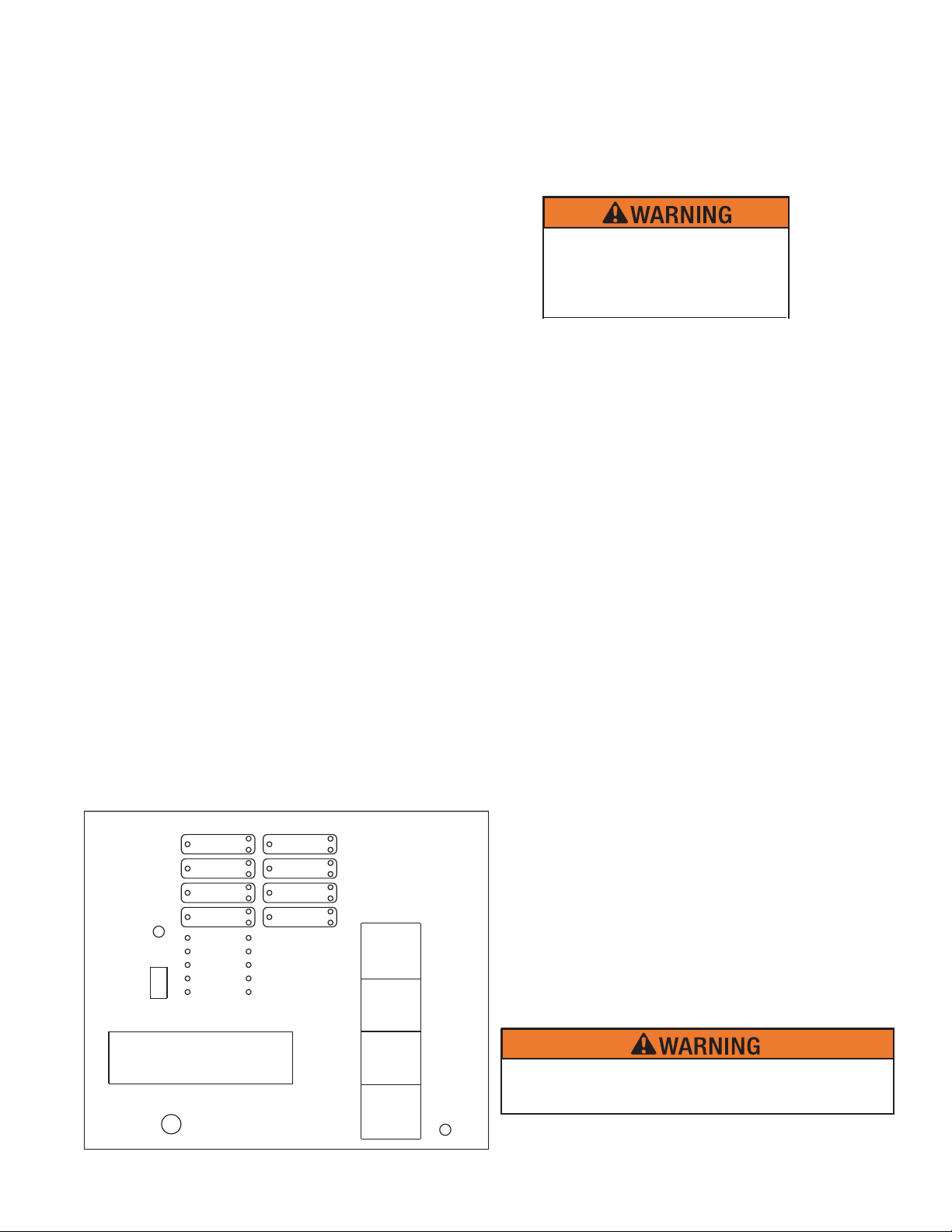
Programming Mode Instructions
To use the Programming Mode push the program switch to the right (see drawing below).
Panel Visual Display
As a general rule, the following applies on the Programming Mode buttons:
The top button (SET) sets the message on the display into the memory.
The middle button (SELECT) scrolls through the selections available for the function displayed.
The bottom button (FUNCTION) allows the user to skip the function without changing the program.
}
RED OUTPUT LED STEADY: ABORT
ZONE 1
ZONE 2
ZONE 3
ZONE 4
OUTPUT 1
OUTPUT 2
OUTPUT 3
OUTPUT 4
AC POWER
POWER TBL
SYSTEM TBL
SUP TBL
GROUND
FAULT
SUP 1/ABORT
SUPERVISORY 2
COMMON ALARM
ALARM SILENCE
STEADY: DISCHARGE
FLASHING:
PRE-DISCHARGE
RUN
PROGRAM
VIEWING ANGLE
PROGRAM
MODE
RUN
MODE
SET
SELECT
FUNCTION
SCROLL-UP
BUZZER SILENCE
LAMP
TEST
SCROLL-DOWN
BUZZER SILENCE
SIGNAL SILENCE
SYSTEM RESET
DWG# 3550-18
After 30 minutes of no activity, the panel will automatically
exit Program Mode and revert to run mode.
Note: The RCDS-1, Release Circuit Disconnect Switch, shall be
used to provide physical means of disconnecting the release
circuit in compliance with NFPA 72, 2007, 6.12.5.2.

18
PFC-4410RC • 5403550 • REV Q • 11/12
There is no capability to back up screens in the program mode. If a mistake was made during programming, move the program
switch back up, then move it down and start from the beginning.
To exit the program mode at any time, move the Program Switch to the left.
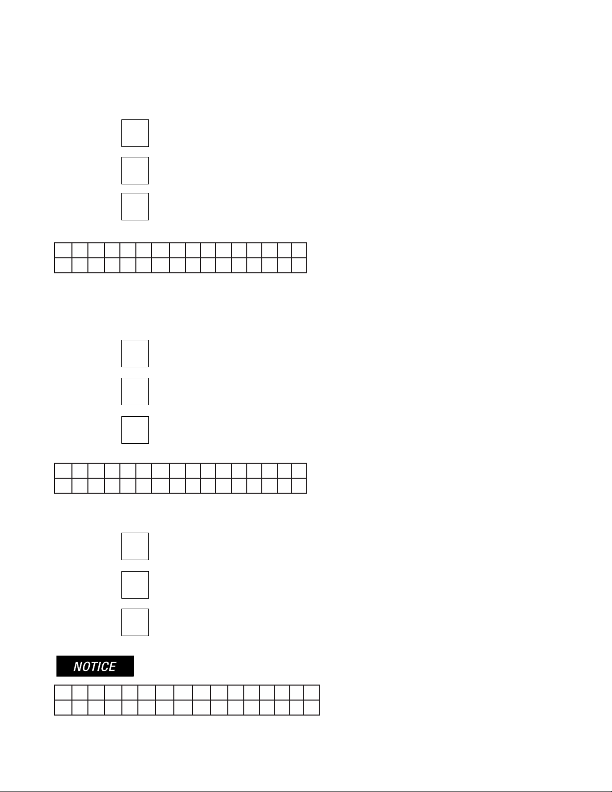
When the programming switch is down (see Panel Visual Display) the following will appear in the display window:
History
To examine the HISTORY press the top button, the display window will show the time and date of the last event or action. To skip
to the next function or to exit history, press the FUNCTION (bottom) button.
SET Press the top button to discover the time and date of the last event or action and to scroll forward.
SELECT To scroll back, press the middle button.
FUNCTION To exit or skip HISTORY, press the bottom button.
To program, push the Program Switch down.
L O O K A T
H I S T O R Y ?
S E T T I M E ?
0 1 / 0 5 / 2 0 0 7
M I N U T E S 0 5 : 1 9 : 3 5
P A S S W O R D = 0 0 0
^
After pressing the FUNCTION (bottom) button the following will appear in the display window:
Date and Time
SELECT To change the time, press the middle button.
FUNCTION To exit to the next function, press the bottom button.
If the middle button is pushed, the date and time will appear in the display window:
The date is shown at the top and the time at the bottom of the display window. “MINUTES” indicates that the user can now
change the minutes.
SET Pressing the top button will decrease the minutes.
SELECT Pressing the middle button will increase the minutes.
FUNCTION When nshed setting the minutes, Press the bottom button. The minutes will change to hours.
Continue this process and change the DAY, MONTH and YEAR. When you have nished changing the year, press the
FUNCTION (bottom) button. A display similar to the following will appear:
19
PFC-4410RC • 5403550 • REV Q • 11/12
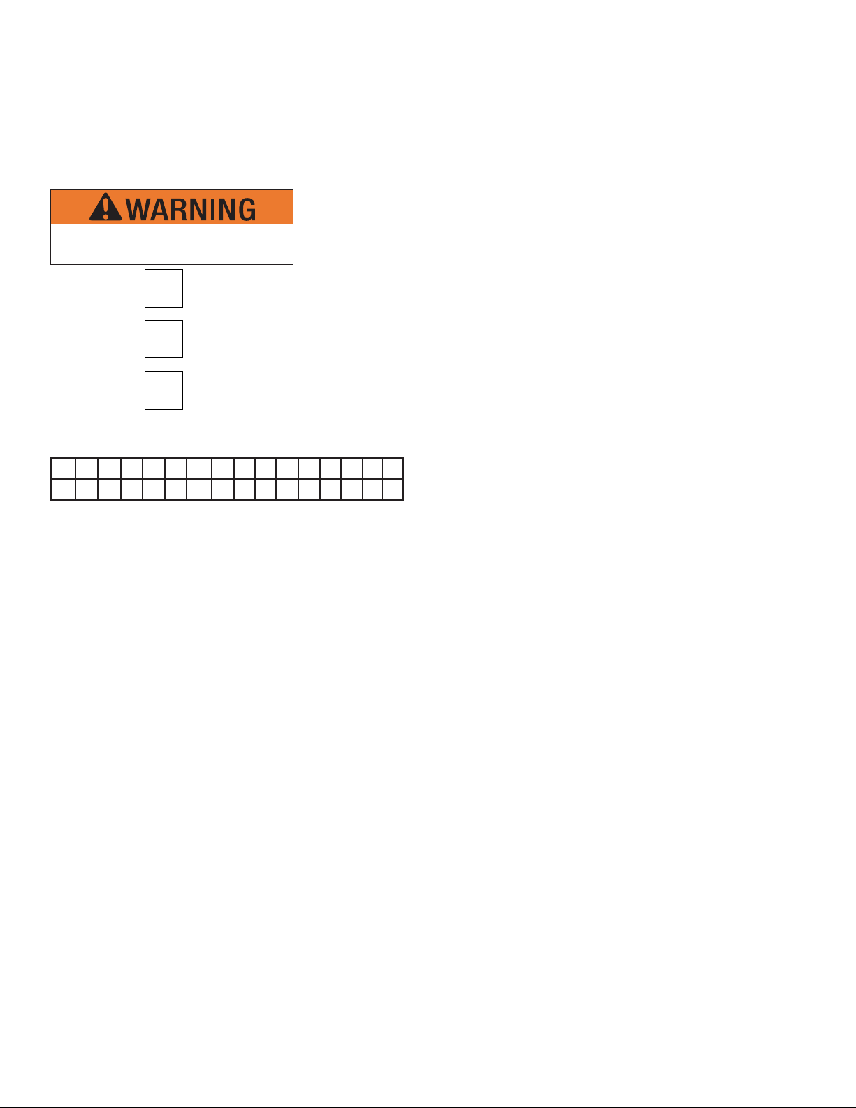
Password
This display prevents unauthorized programming of the panel by requiring the user to enter the proper password. To select the
appropriate number for the space indicated by the ^ symbol, press the middle button. When the proper number is displayed press
the top button to set the number and move to the next space. If the wrong password is entered, the panel will automatically return
to a normal condition. All panels are shipped from the factory with a password of 000. If the password is lost contact Potter.
SET After selecting the desired number, press the top button to set and move to the next number.
SELECT Press the middle button to scroll through the numbers.
FUNCTION Pressing the bottom button will have no effect.
After entering the correct password, a display similar to the following will appear:
Zone Disabled/Enabled
This display allows the user to ENABLE or DISABLE Initiating zones. This display window shows that initiating ZONE #1 is
enabled. To toggle from ENABLED to DISABLED or visa versa, press the SELECT (middle) button.
SET After selecting ENABLED or DISABLED, press the top button to set and move to the next zone.
SELECT Press the middle button to toggle between ENABLED or DISABLED.
FUNCTION To skip to the next function, press the bottom button.
After selecting all four zones or pressing the FUNCTION (bottom) button, the following will appear in the display window:
Output Enable/Disable
This display allows the user to ENABLE or DISABLE any of the output circuits.
SET After selecting ENABLED or DISABLED, press the top button to set and move to the next output.
SELECT Press the middle button to toggle between ENABLED or DISABLED.
FUNCTION To skip to the next function, press the bottom button.
After selecting all four outputs or pressing the FUNCTION (bottom) button, the following will appear in the display window:
Disabling any input or outputs will create a trouble condition on the panel.
I N I T Z O N E # 1
E N A B L E D
O U T P U T # 1
E N A B L E D
S Y S T E M M O D E :
N O R M A L
20
PFC-4410RC • 5403550 • REV Q • 11/12
One Man Walktest
This display allows the user to select system mode NORMAL or ONE MAN WALKTEST by pressing the SELECT (middle)
button to toggle back and forth from NORMAL to ONE MAN WALKTEST. When the desired mode is displayed, press the SET
(top) button. If ONE MAN WALKTEST is selected for test purposes, the display must be restored to the NORMAL setting after
the test is completed by toggling to it using the SELECT (middle) button.
SET After selecting NORMAL or ONE MAN WALKTEST, press the top button to set that mode.
SELECT Press the middle button to toggle between NORMAL and CROSS ZONED.
FUNCTION Press the bottom button to skip to the next function.
After selecting the operating mode or pressing the FUNCTION button a display similar to the following will appear in the display
window:
After 30 minutes of no activity the panel
automatically reverts to normal.
P R O G R A M # 0
Note: NFPA 72, 2007, 6.12.5.2. requires a physical means of disconnecting release
circuits. The Potter Model, RCDS-1, complies with those requirements.

21
PFC-4410RC • 5403550 • REV Q • 11/12
PFC-4410RC Standard Program Information
The PFC-4410RC has 24 standard programs which are detailed in the following pages. Selecting one of these programs will auto-
matically program every function of the panel except the custom
banner and zone message functions.
NOTES:
The release discharge time is continuous for all 24 programs.
In the chemical extinguishing programs the pre-discharge timer defaults to 60 seconds, manual release pre-discharge timer de-
faults to 30 seconds, the abort mode defaults to UL.
The following is an explanation of how the various programs operate and information about the types of devices that are to be
connected to the input and output zones.
If none of the standard programs are acceptable for the installation required, select the custom program #0 then press the SET
(top) button. This will allow the user to custom program the panel. Turn to page 72 for custom program information.
Type Description
Alarm Zones Detection Smoke Detectors, Spot Type Heat Detectors
Waterow PS10 Pressure Switch
Linear Heat Cable Type Heat Detectors
Manual Release Pull Stations
Supervisory Zones Supervisory Valve Tamper, Low Air, High Air, Room Temperature
Low Air supervisory Low Air Switch
High Air High Air Switch
Tamper Valve Tamper Switch
Low Air Alarm * PS10, PS40
Outputs Alarm 24VDC Bells, Horns, Strobes, to indicate an
alarm condition.
Release Solenoid Valve, Squib, Releasing Mechanism
eAEROSOL Aerosol Generator
Supervisory 24VDC Bells, Horns, Strobes, to indicate a
supervisory condition.
Trouble 24VDC Bells, Horns, Strobes, to indicate a
trouble condition.
To program the PFC-4410RC to operate with one of the following 24 standard programs:
The water based extinguishing programs are numbered 1-15. The chemical extinguishing programs are numbered 20-28. A
description, theory of operation, and wiring diagrams for all standard programs start on the next page.
1. Press SELECT (center) button to scroll to the program number (#1 through #15, #20 through #28) you desire.
2. Press SET (top) button.
3. Turn to page 76 to program the banner message and to nish programming the panel.
SET After selecting the proper program number, press the top button to set the program and move to the
next function.
SELECT Press the middle button to scroll through the programs.
FUNCTION Press the bottom button to skip to the next function.
After selecting the desired program number with the middle button, SET (top button) must be
pressed to set the program.
*Not available on Supervisory Zones: Sup 1 or Sup 2.
22
PFC-4410RC • 5403550 • REV Q • 11/12
See page 89 or label inside panel door for smoke detector
compatibility data.
See page 85 for battery information.
10. Maximum resistance on outputs is 10 ohms. Maximum
resistance on outputs programmed as releasing, is 1
divided by current requirements of solenoid.
11. Notication outputs do not provide synchronization.
If synchronization is needed, refer to the NAC table on
page 90. Synchronization is only on one circuit and not
betweeen circuits. The maximum cannot exceed 1 amp or
whatever the maximum that the sync' module can support,
whichever is lower.
+
OUTPUT
1
BATT
2
OUTPUT
ASSY
DIODE
EOL
OUTPUT
3 4
OUTPUT
RED
BLACK
NOCOMNC
NC
NONO
NO
COMCOM
COM
-
-
+
+
+ - + - + -
LIMITED AND
NON-POWER
SUPERVISED
S
BLACK
RED
5.1K
EOLR
BLACK
RED
EOLR
5.1K
BLACK
RED
RELEASEALARM
GENERAL
CIRCUITBELL
ZONE 4
MANUAL
STATION
WATER
FLOW
ZONE 3
SWITCH
ZONE 2ZONE 1
HEAT OR
DETECTORS
SMOKE
SUP 2
PS10
SUP 1/ABORT
EOLR
5.1K
-+-+
ZONE 1
-+ + -
ZONE 2
DRY CONTACTS RATED AT 3A, 30VDC
TROUBLE SUPV
N 120
HOT - BLACK
NEUTRAL - WHITE
EARTH GROUND - GREEN
TO CIRCUIT BREAKER PANEL
120VAC/60Hz
165 VA MAX.
RELAY CONTACTS
ALARM
-
EOLR
5.1K
EOLR
5.1K
5.1K
EOLR
-+ -+ - -+ -+
EOLR
5.1K
220VAC/50Hz
185 VA MAX.
SUPV.
BELL
EOLR
5.1K
RED
BLACK
WATER
FLOW
BELL
AUX.
+ -S
RS-485
+ -
24VNR DC
+ -
POWER
120 OHM
EOLR
5.1K
HEAT OR
SMOKE
DETECTORS
24VR DC
WTRFL
PS10A
OBSERVE POLARITY
WHEN CONNECTING
SMOKE DETECTORS
EACH CA2Z WILL CONVERT
2 CLASS B ZONES INTO 2
CLASS A ZONES
OPTIONAL CLASS A
CONNECTIONS EOLR IS
NOT USED FOR CLASS A
OPTIONAL
CA2Z CLASS
A MODULE
PANEL INPUTS (INITIATING ZONES)
CONNECT TO NORMALLY OPEN DEVICES
OR COMPATIBLE 2 WIRE SMOKE
DETECTORS.
MAXIMUM LINE RESISTANCE: 100 OHMS
(EXCEPT WITH LINEAR HEAT DETECTION)
OPTIONAL CA2Z MOUNTING LOCATION
PROGRAM
SWITCH
BATTERY CABLE
OBSERVE POLARITY
RED +
BLACK -
TROUBLE CONDITION
PANEL PROBLEM
LOSS OF AC
LOSS OF BATTERY
WIRING PROBLEM
ALARM CONDITION
SMOKE DET.
HEAT DET.
PULL STATION
WATERFLOW
SUPERVISORY
LOW AIR
VALVE TAMPER
WATERFLOW
DWG# 3550-1
+
POS
-
NEG
+
POS
-
NEG
12V BATT.
12V BATT.
ZONE 1
ZONE 2
ZONE 3
ZONE 4
OUTPUT 1
OUTPUT 2
OUTPUT 3
OUTPUT 4
PROGRAM
MODE
RUN
MODE
AC POWER
POWER TBL
SYSTEM TBL
SUP TBL
GROUND
FAULT
SUP 1/ABORT
SUPERVISORY 2
COMMON ALARM
ALARM SILENCE
STEADY: DISCHARGING
FLASHING: PRE-
DISCHARGE
RUN
PROGRAM
SET
SELECT
FUNCTION
SCROLL-DOWN
BUZZER SILENCE
SIGNAL SILENCE
SYSTEM RESET
SCROLL-UP
BUZZER SILENCE
VIEWING ANGLE
RED OUTPUT LED STEADY: ABORT
AC IN CONNECTOR
NON-POWER
LIMITED AND
SUPERVISED
+
NOTES:
1. Connect only UL Listed 24VDC devices to indicating
circuits.
2. Connect EOL Diode assembly IN SERIES with solenoid
on release circuit
3. Leave EOLR (provided) on all unused circuits.
4 Polarity is shown on indicating circuits in an activated
(off-normal) condition.
5. Polarity reverses when output is activated.
6. Maximum current per output is 1 Amp. Maximum voltage
is 33 VDC.
7. Outputs identied as Release are Special Application. All
other outputs are Regulated 24 VDC, Rated 1 Amp each,
2.5 Amp total for all 4 circuits.
8. All initiating and NAC/Release circuits are supervised and
power limited. See note 3 on page 92 for power limited
wire routing instructions. All frequencies are continuous.
9. Refer to pgs. 16, 83-85 for installation, test and
maintenance information.
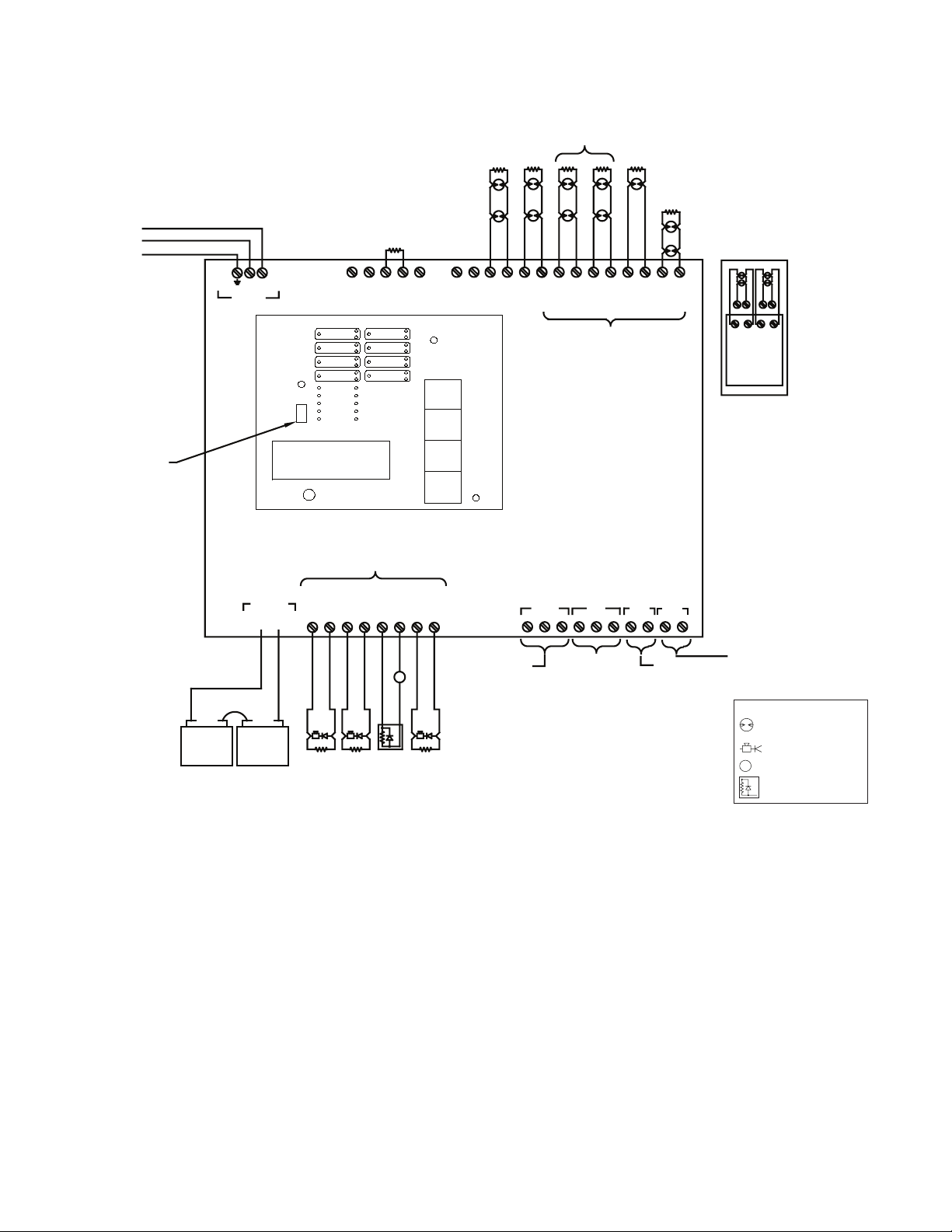
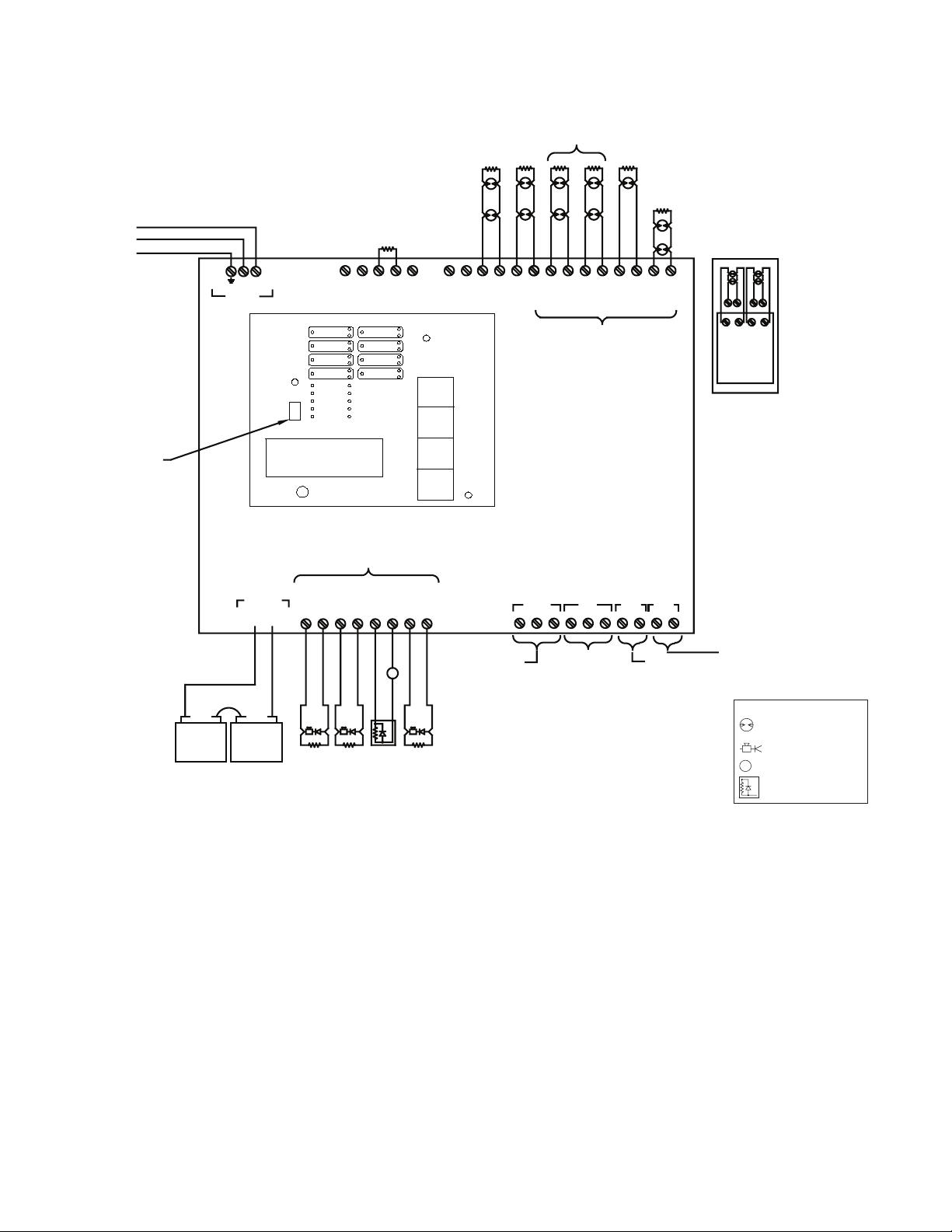
Wiring Diagram Program #1
Single Hazard, 3 Alarm Zones with 1
Waterow Zone and 2 Supervisory Zones
}
LAMP TEST
S
Initiating device
Notication appliance
Solenoid
End-of-Line diode assy
Legend

23
PFC-4410RC • 5403550 • REV Q • 11/12
Program #1 Mode
1. Apply power to panel.
2. Move the program switch down.
3. Press the FUNCTION (bottom) button until the display reads “PASSWORD = 000”.
4. To enter a password, press the SELECT button until the proper number is displayed above the ^ symbol, then press the SET
button to move to the next digit. After entering the third number the display will change. (All panels are shipped with a 000
password.)
5. Press the FUNCTION (bottom) button until the display reads “PROGRAM #0”.
6. Press the SELECT button until the display reads “PROGRAM #1”.
7. Press the SET button.
8. The panel is completely programmed except for the custom banner and zone messages. Move the program switch back up.
Description: Single hazard - 3 zone
Inputs: 2 detection zones, 1 waterow zone, 1 manual release zone, 2 supervisory zones
Outputs: 1 general alarm bell, 1 waterow bell, 1 solenoid release circuit, 1 supervisory bell
Operation: Activation of either detection zone or the manual release zone will operate the release circuit and general alarm output.
Activation of the waterow zone will operate the waterow bell output.
Activation of the supervisory zone will operate the supervisory bell output.
When either zone 1, 2 or 4 is in alarm - output #1 (general alarm) and output #3 (solenoid release) will operate.
When zone 3 is in alarm - output #2 will operate (waterow bell).
When the supervisory zone is activated - output #4 will operate (supervisory bell).
PROGRAM #1
ZONES
SUP 1 SUP 2 #1 #2 #3 #4
OUTPUTS Supervisory Detection Detection Waterow Manual
Release
#1 ALARM INDICATING X X X
#2 ALARM INDICATING X
#3 RELEASE X X X
#4 SUPERVISORY X X
24
PFC-4410RC • 5403550 • REV Q • 11/12
+
OUTPUT
1
BATT
2
OUTPUT
ASSY
DIODE
EOL
OUTPUT
3 4
OUTPUT
RED
BLACK
NOCOMNC
NC
NONO
NO
COMCOM
COM
-
-
+
+
+ - + - + -
LIMITED AND
NON-POWER
SUPERVISED
S
BLACK
RED
5.1K
EOLR
BLACK
RED
EOLR
5.1K
BLACK
RED
RELEASEALARM
GENERAL
CIRCUITBELL
ZONE 4
MANUAL
STATION
WATER
FLOW
ZONE 3
SWITCH
ZONE 2ZONE 1
HEAT OR
DETECTORS
SMOKE
SUP 2
PS10
SUP 1/ABORT
EOLR
5.1K
-+-+
ZONE 1
-+ + -
ZONE 2
DRY CONTACTS RATED AT 3A, 30VDC
TROUBLE SUPV
N 120
HOT - BLACK
NEUTRAL - WHITE
EARTH GROUND - GREEN
TO CIRCUIT BREAKER PANEL
120VAC/60Hz
165 VA MAX.
RELAY CONTACTS
ALARM
-
EOLR
5.1K
EOLR
5.1K
5.1K
EOLR
-+ -+ - -+ -+
EOLR
5.1K
220VAC/50Hz
185 VA MAX.
SUPV.
BELL
EOLR
5.1K
RED
BLACK
WATER
FLOW
BELL
AUX.
+ -S
RS-485
+ -
24VNR DC
+ -
POWER
120 OHM
EOLR
5.1K
HEAT OR
SMOKE
DETECTORS
24VR DC
WTRFL
PS10A
OBSERVE POLARITY
WHEN CONNECTING
SMOKE DETECTORS
EACH CA2Z WILL CONVERT
2 CLASS B ZONES INTO 2
CLASS A ZONES
OPTIONAL CLASS A
CONNECTIONS EOLR IS
NOT USED FOR CLASS A
OPTIONAL
CA2Z CLASS
A MODULE
PANEL INPUTS (INITIATING ZONES)
CONNECT TO NORMALLY OPEN DEVICES
OR COMPATIBLE 2 WIRE SMOKE
DETECTORS.
MAXIMUM LINE RESISTANCE: 100 OHMS
(EXCEPT WITH LINEAR HEAT DETECTION)
OPTIONAL CA2Z MOUNTING LOCATION
PROGRAM
SWITCH
BATTERY CABLE
OBSERVE POLARITY
RED +
BLACK -
TROUBLE CONDITION
PANEL PROBLEM
LOSS OF AC
LOSS OF BATTERY
WIRING PROBLEM
ALARM CONDITION
SMOKE DET.
HEAT DET.
PULL STATION
WATERFLOW
SUPERVISORY
LOW AIR
VALVE TAMPER
WATERFLOW
DWG# 3550-1
+
POS
-
NEG
+
POS
-
NEG
12V BATT.
12V BATT.
ZONE 1
ZONE 2
ZONE 3
ZONE 4
OUTPUT 1
OUTPUT 2
OUTPUT 3
OUTPUT 4
PROGRAM
MODE
RUN
MODE
AC POWER
POWER TBL
SYSTEM TBL
SUP TBL
GROUND
FAULT
SUP 1/ABORT
SUPERVISORY 2
COMMON ALARM
ALARM SILENCE
STEADY: DISCHARGING
FLASHING: PRE-
DISCHARGE
RUN
PROGRAM
SET
SELECT
FUNCTION
SCROLL-DOWN
BUZZER SILENCE
SIGNAL SILENCE
SYSTEM RESET
SCROLL-UP
BUZZER SILENCE
VIEWING ANGLE
RED OUTPUT LED STEADY: ABORT
AC IN CONNECTOR
NON-POWER
LIMITED AND
SUPERVISED
+
See page 89 or label inside panel door for smoke detector
compatibility data.
See page 85 for battery information.
Wiring Diagram Program #2
Single Hazard, 2 Alarm Zones (Cross-Zoned), 1 Manual
Station Zone, 1 Waterow Zone, and 2 Supervisory Zones
}
LAMP TEST
10. Maximum resistance on outputs is 10 ohms. Maximum
resistance on outputs programmed as releasing, is 1
divided by current requirements of solenoid.
11. Notication outputs do not provide synchronization.
If synchronization is needed, refer to the NAC table on
page 90. Synchronization is only on one circuit and not
betweeen circuits. The maximum cannot exceed 1 amp or
whatever the maximum that the sync' module can support,
whichever is lower.
NOTES:
1. Connect only UL Listed 24VDC devices to indicating
circuits.
2. Connect EOL Diode assembly IN SERIES with solenoid
on release circuit
3. Leave EOLR (provided) on all unused circuits.
4 Polarity is shown on indicating circuits in an activated
(off-normal) condition.
5. Polarity reverses when output is activated.
6. Maximum current per output is 1 Amp. Maximum voltage
is 33VDC.
7. Outputs identied as Release are Special Application. All
other outputs are Regulated 24 VDC, Rated 1 Amp each,
2.5 Amp total for all 4 circuits.
8. All initiating and NAC/Release circuits are supervised and
power limited. See note 3 on page 92 for power limited
wire routing instructions. All frequencies are continuous.
9. Refer to pgs. 16, 83-85 for installation, test and
maintenance information.
S
Initiating device
Notication appliance
Solenoid
End-of-Line diode assy
Legend

25
PFC-4410RC • 5403550 • REV Q • 11/12
Program #2 Mode
1. Apply power to panel.
2. Move the program switch down.
3. Press the FUNCTION (bottom) button until the display reads “PASSWORD = 000”.
4. To enter a password, press the SELECT button until the proper number is displayed above the ^ symbol, then press the SET
button to move to the next digit. After entering the third number the display will change. (All panels are shipped with a 000
password.)
5. Press the FUNCTION (bottom) button until the display reads “PROGRAM #0”.
6. Press the SELECT button until the display reads “PROGRAM #2”.
7. Press the SET button.
8. The panel is completely programmed except for the custom banner and zone messages. Move the program switch up.
Description: Single hazard, cross zone with manual station override.
Inputs: 2 detection zones (cross zoned), 1 waterow zone, 1 manual release zone, 2 supervisory zones
Outputs: 1 general alarm bell, 1 waterow bell, 1 solenoid release circuit, 1 supervisory bell
Operation: Activation of both detection zones at the same time, or activation of the manual release zone will operate the release
output and the general alarm output.
Activation of one detection zone will operate the general alarm output.
Activation of the waterow zone will operate the waterow bell output.
Activation of the supervisory zone will operate the supervisory bell output.
When zone 1, 2 or 4 is in alarm - output #1 will operate (general alarm bell).
When zone 3 is in alarm - output #2 will operate (waterow bell).
When both zones 1 and 2 are in alarm at the same time - output #3 will operate (solenoid release).
When zone 4 is in alarm - outputs #3 (solenoid release) and #1 (general alarm) will operate.
PROGRAM #2
ZONES
SUP 1 SUP 2 #1 #2 #3 #4
OUTPUTS Supervisory Detection Detection Waterow Manual
Release
#1 ALARM INDICATING X X X
#2 ALARM INDICATING X
#3 RELEASE XX XX X
#4 SUPERVISORY X X
XX = Cross-Zoned
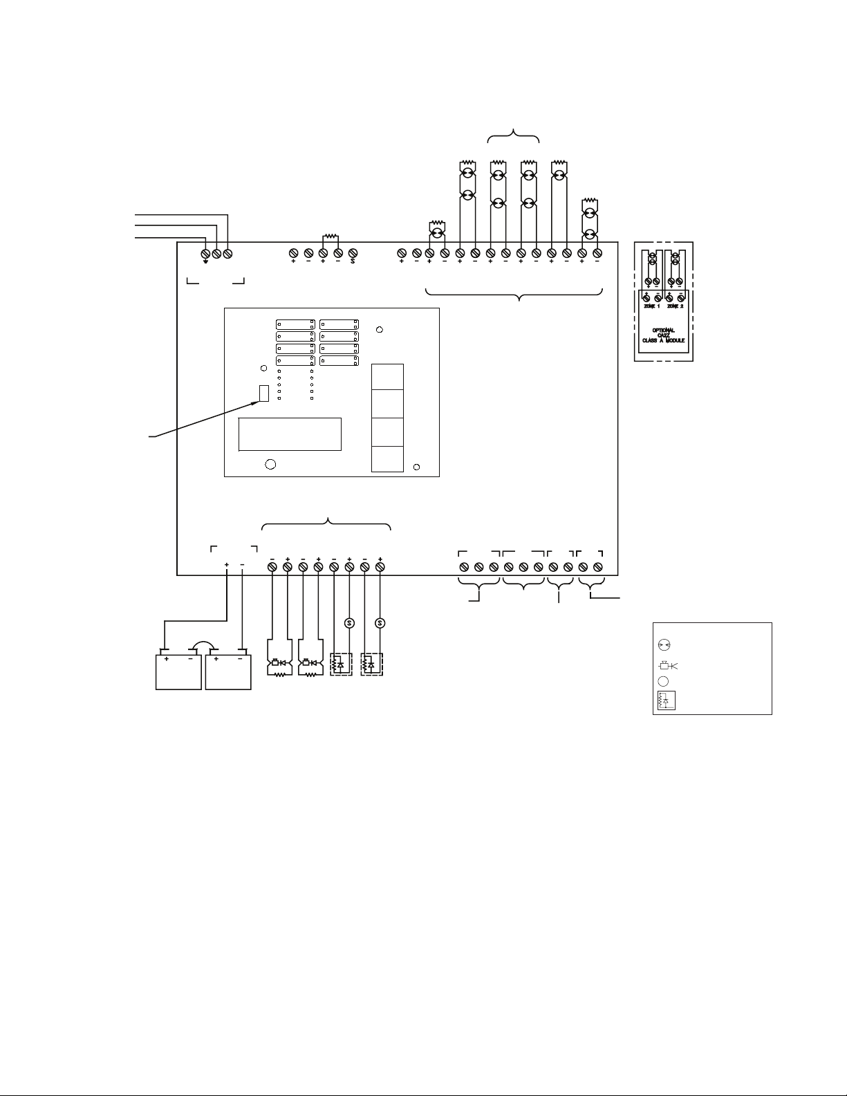
26
PFC-4410RC • 5403550 • REV Q • 11/12
See page 89 or label inside panel door for smoke detector
compatibility data.
See page 85 for battery information.
Wiring Diagram Program #3
Dual Hazard, Combined Release - 2 Alarm Zones, 1 Manual
Station Zone, 1 Waterow Zone, and 2 Supervisory Zones
OBSERVE POLARITY
WHEN CONNECTING
SMOKE DETECTORS
5.1K
EOLR
5.1K
EOLR
5.1K
EOLR
5.1K
EOLR
5.1K
EOLR
PS10A
LOW AIR
PS10A
VALVE
TAMPER
OSYSU
PCVS
EOLR
AUX.
POWER
24VR DC
SUP 1/
ABORT
SUPV 2
ZONE 1
HEAT OR
SMOKE
DETECTORS
ZONE 2
HEAT OR
SMOKE
DETECTORS
ZONE 3
WATERFLOW
SWITCH
PS10
ZONE 4
MANUAL
STATION
PANEL INPUTS (INITIATING ZONES)
CONNECT TO NORMALLY OPEN DEVICES
OR COMPATIBLE 2 WIRE SMOKE
DETECTORS.
MAXIMUM LINE RESISTANCE: 100 OHMS
(EXCEPT WITH LINEAR HEAT DETECTION)
OPTIONAL CA2Z MOUNTING LOCATION
EACH CA2Z WILL CONVERT
2 CLASS B ZONES INTO 2
CLASS A ZONES
OPTIONAL CLASS A
CONNECTIONS EOLR IS
NOT USED FOR CLASS A
DWG #3550-2
NOCOMNC
NC
NONO
NO
COMCOM
COM
TROUBLE SUPVALARM
SUPERVISORY
LOW AIR
VALVE TAMPER
WTRFL
ALARM CONDITION
SMOKE DET.
HEAT DET.
PULL STAT ION
WATERFLOW
WATERFLOW
TROUBLE CONDITION
PANEL PROBLEM
LOSS OF AC
LOSS OF BATTERY
WIRING PROBLEM
RELAY CONTACTS
DRY CONTACTS RATED AT 3A, 30VDC RESISTIVE
RED
RED
RED
RED
RED
BLACK
BLACK
BLACK
BLACK
BLACK
EOL
DIODE
ASSY
EOL
DIODE
ASSY
5.1K
EOLR
5.1K
EOLR
RELEASE
CIRCUIT
OUTPUT
4
RELEASE
CIRCUIT
OUTPUT
3
SUPV
BELL
OUTPUT
2
GENERAL
ALARM
BELL
OUTPUT
1
12V BATT.
12V BATT.
POS NEG POS NEG
BATTERY CABLE
OBSERVE POLARITY
RED +
BLACK -
NON-POWER
LIMITED AND
SUPERVISED
BATT
PANEL OUTPUTS (INDICATING CIRCUITS)
PROGRAM
SWITCH
NON-POWER
LIMITED AND
SUPERVISED
AC IN
CONNECTOR
24 VNR DC RS-485
120 OHM
TO CIRCUIT BREAKER PANEL
120VAC/60Hz
165 VA MAX.
220 VAC/50Hz
185 VA MAX.
HOT - BLACK
NEUTRAL - WHITE
EARTH GROUND - GREEN
ZONE 1
ZONE 2
ZONE 3
ZONE 4
OUTPUT 1
OUTPUT 2
OUTPUT 3
OUTPUT 4
PROGRAM
MODE
RUN
MODE
AC POWER
POWER TBL
SYSTEM TBL
SUP TBL
GROUND
FAULT
SUP 1/ABORT
SUPERVISORY 2
COMMON ALARM
ALARM SILENCE
STEADY: DISCHARGING
FLASHING: PRE-
DISCHARGE
RUN
PROGRAM
SET
SELECT
FUNCTION
SCROLL-DOWN
BUZZER SILENCE
SIGNAL SILENCE
SYSTEM RESET
SCROLL-UP
BUZZER SILENCE
VIEWING ANGLE
RED OUTPUT LED STEADY: ABORT
N 120
}
LAMP TEST
10. Maximum resistance on outputs is 10 ohms. Maximum
resistance on outputs programmed as releasing, is 1
divided by current requirements of solenoid.
11. Notication outputs do not provide synchronization.
If synchronization is needed, refer to the NAC table on
page 90. Synchronization is only on one circuit and not
betweeen circuits. The maximum cannot exceed 1 amp or
whatever the maximum that the sync' module can support,
whichever is lower.
NOTES:
1. Connect only UL Listed 24VDC devices to indicating
circuits.
2. Connect EOL Diode assembly IN SERIES with solenoid
on release circuit
3. Leave EOLR (provided) on all unused circuits.
4 Polarity is shown on indicating circuits in an activated
(off-normal) condition.
5. Polarity reverses when output is activated.
6. Maximum current per output is 1 Amp. Maximum voltage
is 33VDC.
7. Outputs identied as Release are Special Application. All
other outputs are Regulated 24 VDC, Rated 1 Amp each,
2.5 Amp total for all 4 circuits.
8. All initiating and NAC/Release circuits are supervised and
power limited. See note 3 on page 92 for power limited
wire routing instructions. All frequencies are continuous.
9. Refer to pgs. 16, 83-85 for installation, test and
maintenance information.
S
Initiating device
Notication appliance
Solenoid
End-of-Line diode assy
Legend
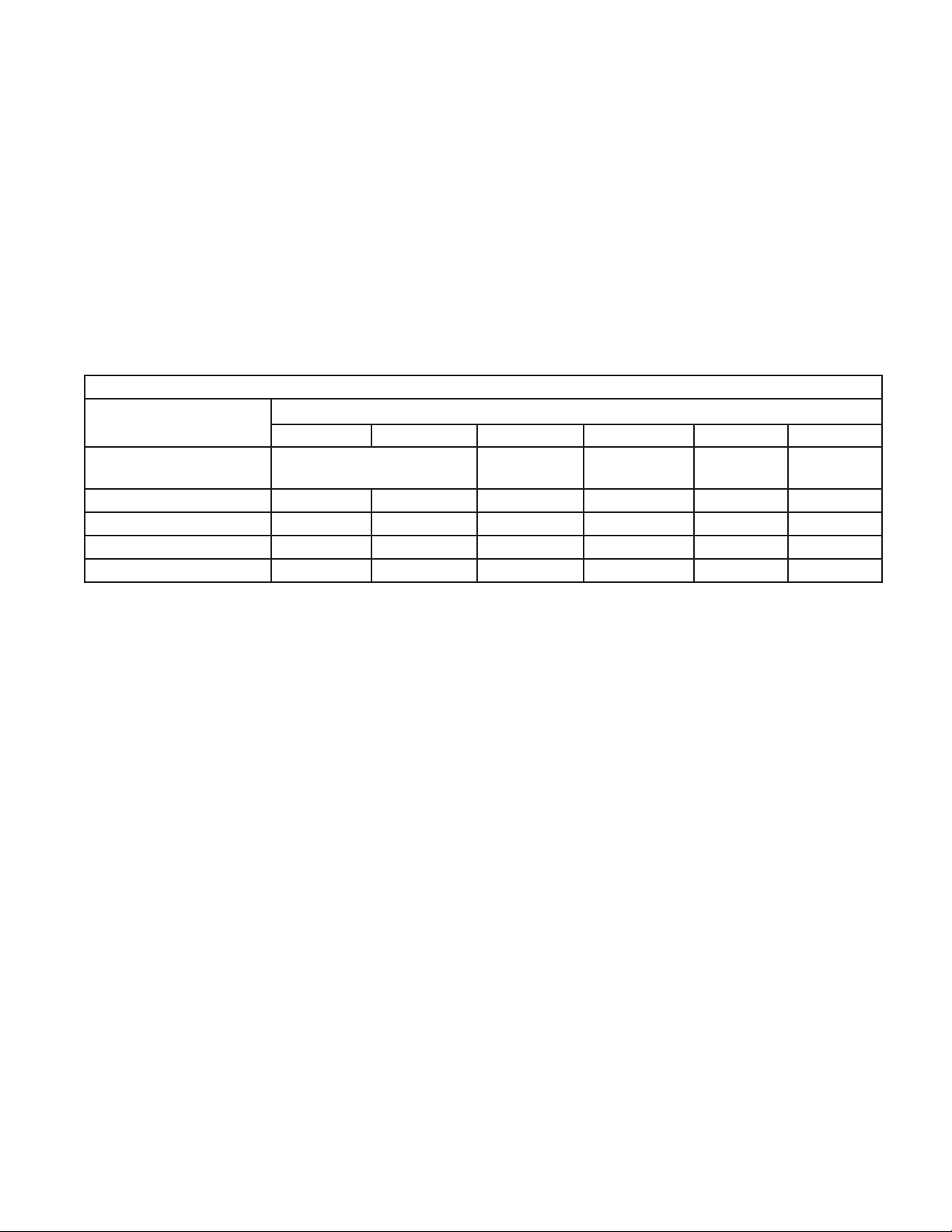
27
PFC-4410RC • 5403550 • REV Q • 11/12
Program #3 Mode
1. Apply power to panel.
2. Move the program switch down.
3. Press the FUNCTION (bottom) button until the display reads “PASSWORD = 000”.
4. To enter a password, press the SELECT button until the proper number is displayed above the ^ symbol, then press the SET
button to move to the next digit. After entering the third number the display will change. (All panels are shipped with a 000
password.)
5. Press the FUNCTION (bottom) button until the display reads “PROGRAM #0”.
6. Press the SELECT button until the display reads “PROGRAM #3”.
7. Press the SET button.
8. The panel is completely programmed except for the custom banner and zone messages. Move the program switch back up.
Description: Dual hazard, combined release.
Inputs: 2 detection zones, 1 waterow zone, 1 manual release zone, 2 supervisory zones
Outputs: 1 general alarm bell, 1 supervisory bell, 2 solenoid release circuits
Operation: Activation of either detection zone or the manual release zone will activate both solenoid release outputs and the
general alarm bell.
Activation of the waterow zone will operate the general alarm bell.
Activation of the supervisory zone will operate the supervisory bell output.
When either zone 1, 2 or 4 is in alarm - outputs #1 (general alarm), #3 and #4 (solenoid release) will operate.
When zone 3 is in alarm - output #1 (general alarm) will operate.
When the supervisory zone is activated - output #2 (supervisory bell) will operate.
PROGRAM #3
ZONES
SUP 1 SUP 2 #1 #2 #3 #4
OUTPUTS Supervisory Detection Detection Waterow Manual
Release
#1 ALARM INDICATING X X X X
#2 SUPERVISORY X X
#3 RELEASE X X X
#4 RELEASE X X X
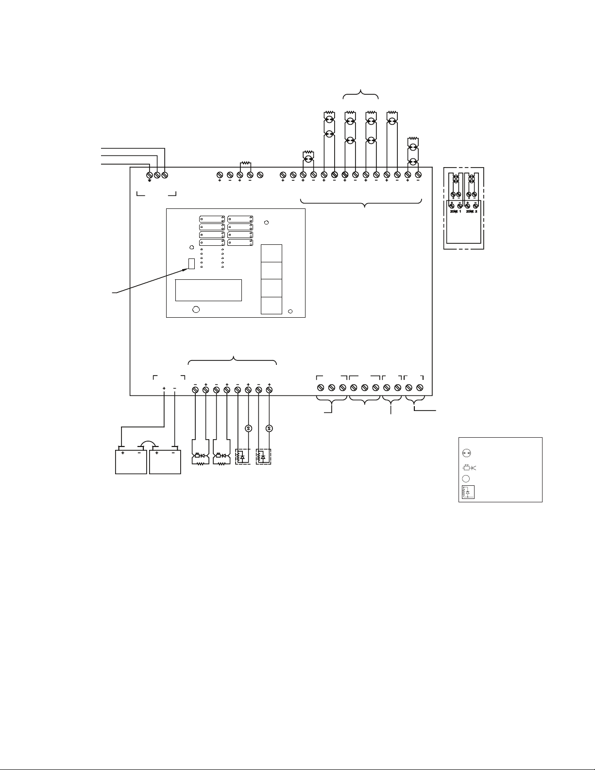
28
PFC-4410RC • 5403550 • REV Q • 11/12
OBSERVE POLARITY
WHEN CONNECTING
SMOKE DETECTORS
5.1K
EOLR
5.1K
EOLR
5.1K
EOLR
5.1K
EOLR
5.1K
EOLR
PS10A
LOW AIR
PS10A
VALVE
TAMPER
OSYSU
PVCS
EOLR
AUX.
POWER
24VR DC
SUP 1/
ABORT
SUPV 2
ZONE 1
HEAT OR
SMOKE
DETECTORS
ZONE 2
HEAT OR
SMOKE
DETECTORS
ZONE 3
WATERFLOW
SWITCH
PS10
ZONE 4
SUPV
PANEL INPUTS (INITIATING ZONES)
CONNECT TO NORMALLY OPEN DEVICES
OR COMPATIBLE 2 WIRE SMOKE
DETECTORS.
MAXIMUM LINE RESISTANCE: 100 OHMS
(EXCEPT WITH LINEAR HEAT DETECTION)
OPTIONAL CA2Z MOUNTING LOCATION
EACH CA2Z WILL
CONVERT 2 CLASS B
ZONES INTO 2
CLASS A ZONES
OPTIONAL CLASS A
CONNECTIONS
EOLR IS NOT USED
FOR CLASS A
OPTIONAL
CA2Z CLASS
A MOULE
DWG #3550-3
NOCOMNC
NC
NONO
NO
COMCOM
COM
TROUBLE SUPVALARM
SUPERVISORY
LOW AIR
VALVE TAMPER
WTRFL
ALARM CONDITION
SMOKE DET.
HEAT DET.
PULL STATION
WATERFLOW
WATERFLOW
TROUBLE CONDITION
PANEL PROBLEM
LOSS OF AC
LOSS OF BATTERY
WIRING PROBLEM
RELAY CONTACTS
DRY CONTACTS RATED AT 3A, 30VDC RESISTIVE
EOL
DIODE
ASSY
5.1K
EOLR
5.1K
EOLR
RED
RED
RED
BLACK
BLACK
BLACK
BLACK
RED
RELEASE
CIRCUIT
OUTPUT
4
RELEASE
CIRCUIT
OUTPUT
3
SUPV
BELL
OUTPUT
2
GENERAL
ALARM
BELL
OUTPUT
1
12V BATT.
12V BATT.
POS NEG
POS NEG
BATTERY CABLE
OBSERVE POLARITY
RED +
BLACK -
NON-POWER
LIMITED AND
SUPERVISED
BATT
PANEL OUTPUTS (INDICATING CIRCUITS)
PROGRAM
SWITCH
NON-POWER
LIMITED AND
SUPERVISED
TO CIRCUIT BREAKER PANEL
120VAC/60Hz
165 VA MAX.
220VAC/50Hz
185 VA MAX.
HOT - BLACK
NEUTRAL - WHITE
EARTH GROUND - GREEN
AC IN
CONNECTOR
24VNR DC
RS-485
120 OHM
S
EOL
DIODE
ASSY
RED
BLACK
ZONE 1
ZONE 2
ZONE 3
ZONE 4
OUTPUT 1
OUTPUT 2
OUTPUT 3
OUTPUT 4
PROGRAM
MODE
RUN
MODE
AC POWER
POWER TBL
SYSTEM TBL
SUP TBL
GROUND
FAULT
SUP 1/ABORT
SUPERVISORY 2
COMMON ALARM
ALARM SILENCE
STEADY: DISCHARGING
FLASHING: PRE-
DISCHARGE
RUN
PROGRAM
SET
SELECT
FUNCTION
SCROLL-DOWN
BUZZER SILENCE
SIGNAL SILENCE
SYSTEM RESET
SCROLL-UP
BUZZER SILENCE
VIEWING ANGLE
RED OUTPUT LED STEADY: ABORT
N 120
See page 89 or label inside panel door for smoke detector
compatibility data.
See page 85 for battery information.
Wiring Diagram Program #4
Dual Hazard, Split-Release - 2 Alarm Zones, 1 Waterow Zone,
and 2 Supervisory Zones
}
LAMP TEST
10. Maximum resistance on outputs is 10 ohms. Maximum
resistance on outputs programmed as releasing, is 1
divided by current requirements of solenoid.
11. Notication outputs do not provide synchronization.
If synchronization is needed, refer to the NAC table on
page 90. Synchronization is only on one circuit and not
betweeen circuits. The maximum cannot exceed 1 amp or
whatever the maximum that the sync' module can support,
whichever is lower.
NOTES:
1. Connect only UL Listed 24VDC devices to indicating
circuits.
2. Connect EOL Diode assembly IN SERIES with solenoid
on release circuit
3. Leave EOLR (provided) on all unused circuits.
4 Polarity is shown on indicating circuits in an activated
(off-normal) condition.
5. Polarity reverses when output is activated.
6. Maximum current per output is 1 Amp. Maximum voltage
is 33VDC.
7. Outputs identied as Release are Special Application. All
other outputs are Regulated 24 VDC, Rated 1 Amp each,
2.5 Amp total for all 4 circuits.
8. All initiating and NAC/Release circuits are supervised and
power limited. See note 3 on page 92 for power limited
wire routing instructions. All frequencies are continuous.
9. Refer to pgs. 16, 83-85 for installation, test and
maintenance information.
S
Initiating device
Notication appliance
Solenoid
End-of-Line diode assy
Legend

29
PFC-4410RC • 5403550 • REV Q • 11/12
Program #4 Mode
1. Apply power to panel.
2. Move the program switch down.
3. Press the FUNCTION (bottom) button until the display reads “PASSWORD = 000”.
4. To enter a password, press the SELECT button until the proper number is displayed above the ^ symbol, then press the SET
button to move to the next digit. After entering the third number the display will change. (All panels are shipped with a 000
password.)
5. Press the FUNCTION (bottom) button until the display reads “PROGRAM #0”.
6. Press the SELECT button until the display reads “PROGRAM #4”.
7. Press the SET button.
8. The panel is completely programmed except for the custom banner and zone messages. Move the program switch up.
Description: Dual hazard, split release.
Inputs: 2 detection zones, 1 waterow zone, 3 supervisory zones
Outputs: 1 general alarm bell, 1 supervisory bell, 2 solenoid release circuits
Operation: Activation of detection zone #1 will operate solenoid release circuit #1 (output #3) and the general alarm bell.
Activation of detection zone #2 will operate solenoid release circuit #2 (output #4) and the general alarm bell.
Activation of zone #3 (Waterow) will operate output #1 (General Alarm).
Activation of either supervisory zone will operate the supervisory bell.
When zone 1 is in alarm - output #1 (general alarm) and output #3 (solenoid release #1) will operate.
When zone 2 is in alarm - output #1 (general alarm) and output #4 (solenoid release #2) will operate.
When either zone 4 or the supervisory zones are activated - output #2 (supervisory bell) will operate.
PROGRAM #4
ZONES
SUP 1 SUP 2 #1 #2 #3 #4
OUTPUTS Supervisory Detection Detection Waterow Supervisory
#1 ALARM INDICATING X X X
#2 SUPERVISORY X X X
#3 RELEASE X
#4 RELEASE X

30
PFC-4410RC • 5403550 • REV Q • 11/12
OBSERVE POLARITY
WHEN CONNECTING
SMOKE DETECTORS
5.1K
EOLR
5.1K
EOLR
5.1K
EOLR
5.1K
EOLR
5.1K
EOLR
PS10A
LOW AIR
PS10A
VALVE
TAMPER
OSYSU
PVCS
EOLR
AUX.
POWER
24VR DC
SUP 1/
ABORT
SUPV 2
ZONE 1
HEAT OR
SMOKE
DETECTORS
ZONE 2
HEAT OR
SMOKE
DETECTORS
ZONE 3
WATERFLOW
SWITCH
PS10
ZONE 4
MANUAL
STATION
PANEL INPUTS (INITIATING ZONES)
CONNECT TO NORMALLY OPEN DEVICES
OR COMPATIBLE 2 WIRE SMOKE
DETECTORS.
MAXIMUM LINE RESISTANCE: 100 OHMS
(EXCEPT WITH LINEAR HEAT DETECTION)
OPTIONAL CA2Z MOUNTING LOCATION
EACH CA2Z WILL
CONVERT 2 CLASS B
ZONES INTO 2
CLASS A ZONES
OPTIONAL CLASS A
CONNECTIONS
EOLR IS NOT USED
FOR CLASS A
OPTIONAL
CA2Z CLASS
A MOULE
DWG #3550-4
NOCOMNC
NC
NONO
NO
COMCOM
COM
TROUBLE SUPVALARM
SUPERVISORY
LOW AIR
VALVE TAMPER
WTRFL
ALARM CONDITION
SMOKE DET.
HEAT DET.
PULL STATION
WATERFLOW
WATERFLOW
TROUBLE CONDITION
PANEL PROBLEM
LOSS OF AC
LOSS OF BATTERY
WIRING PROBLEM
RELAY CONTACTS
DRY CONTACTS RATED AT 3A, 30VDC RESISTIVE
EOL
DIODE
ASSY
5.1K
EOLR
5.1K
EOLR
RED
RED
RED
BLACK
BLACK
BLACK
BLACK
RED
RELEASE
CIRCUIT
OUTPUT
4
SPRVSRY
BELL
OUTPUT
3
TROUBLE
BELL
OUTPUT
2
GENERAL
ALARM
BELL
OUTPUT
1
12V BATT.
12V BATT.
POS NEG
POS NEG
BATTERY CABLE
OBSERVE POLARITY
RED +
BLACK -
NON-POWER
LIMITED AND
SUPERVISED
BATT
PANEL OUTPUTS (INDICATING CIRCUITS)
PROGRAM
SWITCH
NON-POWER
LIMITED AND
SUPERVISED
TO CIRCUIT BREAKER PANEL
120VAC/60Hz
165 VA MAX.
220VAC/50Hz
185 VA MAX.
HOT - BLACK
NEUTRAL - WHITE
EARTH GROUND - GREEN
AC IN
CONNECTOR
24VNR DC
RS-485
120 OHM
S
5.1K
EOLR
RED
BLACK
ZONE 1
ZONE 2
ZONE 3
ZONE 4
OUTPUT 1
OUTPUT 2
OUTPUT 3
OUTPUT 4
PROGRAM
MODE
RUN
MODE
AC POWER
POWER TBL
SYSTEM TBL
SUP TBL
GROUND
FAULT
SUP 1/ABORT
SUPERVISORY 2
COMMON ALARM
ALARM SILENCE
STEADY: DISCHARGING
FLASHING: PRE-
DISCHARGE
RUN
PROGRAM
SET
SELECT
FUNCTION
SCROLL-DOWN
BUZZER SILENCE
SIGNAL SILENCE
SYSTEM RESET
SCROLL-UP
BUZZER SILENCE
VIEWING ANGLE
RED OUTPUT LED STEADY: ABORT
N
120
See page 89 or label inside panel door for smoke detector
compatibility data.
See page 85 for battery information.
Wiring Diagram Program #5
Single Hazard with Trouble Bell - 2 Alarm Zones, 1 Manual
Station Zone, 1 Waterow Zone, and 2 Supervisory Zones
}
LAMP TEST
10. Maximum resistance on outputs is 10 ohms. Maximum
resistance on outputs programmed as releasing, is 1
divided by current requirements of solenoid.
11. Notication outputs do not provide synchronization.
If synchronization is needed, refer to the NAC table on
page 90. Synchronization is only on one circuit and not
betweeen circuits. The maximum cannot exceed 1 amp or
whatever the maximum that the sync' module can support,
whichever is lower.
NOTES:
1. Connect only UL Listed 24VDC devices to indicating
circuits.
2. Connect EOL Diode assembly IN SERIES with solenoid
on release circuit
3. Leave EOLR (provided) on all unused circuits.
4 Polarity is shown on indicating circuits in an activated
(off-normal) condition.
5. Polarity reverses when output is activated.
6. Maximum current per output is 1 Amp. Maximum voltage
is 33VDC.
7. Outputs identied as Release are Special Application. All
other outputs are Regulated 24 VDC, Rated 1 Amp each,
2.5 Amp total for all 4 circuits.
8. All initiating and NAC/Release circuits are supervised and
power limited. See note 3 on page 92 for power limited
wire routing instructions. All frequencies are continuous.
9. Refer to pgs. 16, 83-85 for installation, test and
maintenance information.
S
Initiating device
Notication appliance
Solenoid
End-of-Line diode assy
Legend
 Loading...