


PFC-6030 Fire Alarm
Control Panel
Installation, Operation & Programming Manual
Potter Electric Signal Company, LLC
St. Louis, MO
Customer Service: (866) 240-1870 • Technical Support: (866) 956-1211 • Fax: (314) 595-6999
www.pottersignal.com
Manual #5403595–Rev C 2/13

PFC-6030 • 5403595 • Rev C • 2/13
WARRANTY INFORMATION
The essential purpose of any sale or contract for sale of any of the products listed in the POTTER catalog or price list is the furnishing of that product. It is expressly understood that in furnishing said product, POTTER does not agree to insure the Purchaser against any losses the Purchaser may incur, even if resulting from the malfunction of said product.
POTTER warrants that the equipment herein shall conform to said descriptions as to all affirmation of fact and shall be free from defects of manufacture, labeling and packaging for a period of one (1) or five (5) year(s), depending on the product, from the invoice date to the original purchaser, provided that representative samples are returned to POTTER for inspection. The product warranty period is stated on
the exterior of the product package. Upon a determination by POTTER that a product is not as warranted, POTTER shall, at its exclusive option, replace or repair said defective product or parts thereof at its own expense except that Purchaser shall pay all shipping, insurance and similar charges incurred in connection with the replacement of the defective product or parts thereof. This Warranty is void in the case of abuse, misuse, abnormal usage, faulty installation or repair by unauthorized persons, or if for any other reason POTTER determines that said product is not operating properly as a result of causes other than defective manufacture, labeling or packaging.
The Aforesaid Warranty Is Expressly Made In Lieu Of Any Other Warranties, Expressed Or Implied, It Being Understood That All Such Other Warranties, Expressed Or Implied, Including The Warranties Of Merchantability And Fitness For Particular Purpose Are Hereby Expressly Excluded. In No Event Shall Potter Be Liable To Purchaser For Any Direct, Collateral, Incidental Or Consequential Damages In
Connection With Purchaser’s Use Of Any Of The Products Listed Herein, Or For Any Other Cause Whatsoever Relating To The Said Products. Neither Potter Nor Its Representatives Shall Be Liable To The Purchaser
Or Anyone Else For Any Liability, Claim, Loss, Damage Or Expense Of Any Kind, Or Direct Collateral, Incidental Or Consequential Damages Relative To Or Arising From Or Caused Directly Or Indirectly By Said
Products Or The Use Thereof Or Any Deficiency, Defect Or Inadequacy Of The Said Products. It Is Expressly
Agreed That Purchaser’s Exclusive Remedy For Any Cause Of Action Relating To The Purchase And/or Use Of Any Of The Products Listed Herein From Potter Shall Be For Damages, And Potter's Liability For Any And All Losses Or Damages Resulting From Any Cause Whatsoever, Including Negligence, Or Other Fault, Shall In No Event Exceed The Purchase Price Of The Product In Respect To Which The Claim Is Made, Or At The Election Of Potter, The Restoration Or Replacement Or Repair Of Such Product.
Potter Electric Signal Company, LLC
5757 Phantom Drive Ste 125 • St. Louis, MO 63042 • 314-595-6900 • 800-325-3936
2
PFC-6030 • 5403595 • Rev C • 2/13 |
|
Table of Contents |
|
Section 1: Introduction.............................................................................................................................. |
1-1 |
Purpose of This Manual........................................................................................................................... |
1-1 |
System Overview..................................................................................................................................... |
1-1 |
System Features....................................................................................................................................... |
1-1 |
P-Link Accessories............................................................................................................................ |
1-1 |
SLC Loop Accessories....................................................................................................................... |
1-2 |
Addressable Sensors.......................................................................................................................... |
1-2 |
Addressable Modules......................................................................................................................... |
1-2 |
How to Use this Manual.......................................................................................................................... |
1-2 |
Common Terminology............................................................................................................................. |
1-2 |
Section 2: Before You Start Installation.................................................................................................. |
2-3 |
System Specifications.............................................................................................................................. |
2-3 |
Environmental Specifications.................................................................................................................. |
2-3 |
System Configurations / Appliances........................................................................................................ |
2-3 |
Electrical Specifications.......................................................................................................................... |
2-4 |
System Size Specifications...................................................................................................................... |
2-4 |
Main Board Wiring Specifications.......................................................................................................... |
2-5 |
Circuit Separation............................................................................................................................. |
2-5 |
Wiring Types...................................................................................................................................... |
2-5 |
Cabinet Dimensions................................................................................................................................. |
2-6 |
Cabinet Wiring Connections.................................................................................................................... |
2-7 |
Battery Circuit Calculations.................................................................................................................... |
2-8 |
Battery Calculation Worksheets.............................................................................................................. |
2-8 |
SLC Current Draw Worksheet................................................................................................................. |
2-9 |
Isolator Device Load Calculation.......................................................................................................... |
2-10 |
Scenario 1: Class A Loop – Isolated Devices Configuration.......................................................... |
2-10 |
Scenario 2: Class B Loop – Isolated Branch Configuration........................................................... |
2-11 |
Battery Connections.............................................................................................................................. |
2-12 |
Main Supply Circuit.............................................................................................................................. |
2-12 |
Section 3: Installation.............................................................................................................................. |
3-13 |
Signaling Line Circuit (SLC) Installation............................................................................................. |
3-13 |
SLC Wiring Requirements................................................................................................................ |
3-13 |
Class B, Style 4 Wiring Configuration............................................................................................. |
3-13 |
Class A, Style 6 Wiring Configuration............................................................................................. |
3-14 |
Class A, Style 7 Wiring Configuration............................................................................................. |
3-14 |
Connecting Analog Detectors................................................................................................................ |
3-15 |
Connecting Addressable Modules......................................................................................................... |
3-15 |
Conventional Initiating Zones (CIZM-4) Class A........................................................................... |
3-15 |
Conventional Initiating Zones (CIZM-4) Class B........................................................................... |
3-16 |
Single Contact Module – 4 inch Mount (SCM-4)............................................................................ |
3-16 |
Dual Contact Module – 4 inch Mount (DCM-4)............................................................................. |
3-17 |
Twin Relay Module – 4 inch mount (TRM-4).................................................................................. |
3-17 |
Monitored Output Module – 4 inch mount (MOM-4)...................................................................... |
3-18 |
Analog Sounder Base (ASB)............................................................................................................ |
3-18 |
Analog Relay Base (ARB)................................................................................................................ |
3-18 |
Single Action / Dual Action Pull Station (APS-SA / APS-DA)........................................................ |
3-19 |
Addressing SLC Devices....................................................................................................................... |
3-20 |
3
PFC-6030 • 5403595 • Rev C • 2/13 |
|
Notification Appliance Circuits Installation.......................................................................................... |
3-22 |
NAC Wiring..................................................................................................................................... |
3-22 |
NAC Maximum Wiring Impedance Formula................................................................................... |
3-22 |
NAC Wiring Configurations ........................................................................................................... |
3-22 |
Relay Output Wiring.............................................................................................................................. |
3-24 |
CA-6075 Class A Expander Installation................................................................................................ |
3-24 |
P-Link Devices...................................................................................................................................... |
3-25 |
Configuration Characteristics......................................................................................................... |
3-25 |
Maximum Wire Resistance Formula................................................................................................ |
3-25 |
P-Link Addresses............................................................................................................................. |
3-26 |
Remote Annunciators Installation (RA-6500 and RA-6075)................................................................ |
3-27 |
Setting Addresses............................................................................................................................. |
3-27 |
LED Annunciators Installation (LED-16)............................................................................................. |
3-27 |
LED Drivers Installation (DRV-50)....................................................................................................... |
3-28 |
Relay Board Installation (RLY-5).......................................................................................................... |
3-30 |
Fire Communications Bridge Installation (FCB-1000)......................................................................... |
3-31 |
Fiber Interface Bridge Installation (FIB-1000)..................................................................................... |
3-32 |
FIB-1000 Wiring.............................................................................................................................. |
3-33 |
Serial Parallel Gateway Installation (SPG-1000).................................................................................. |
3-34 |
DACT Installation................................................................................................................................. |
3-35 |
P-Link & Dip Switch Locations....................................................................................................... |
3-36 |
Section 4: Operation................................................................................................................................ |
4-37 |
Control Panel Basic Operation.............................................................................................................. |
4-37 |
LCD Display.................................................................................................................................... |
4-37 |
Menu Navigation Keys..................................................................................................................... |
4-38 |
Numeric Keypad.............................................................................................................................. |
4-38 |
Function Pushbuttons...................................................................................................................... |
4-38 |
Status LEDs..................................................................................................................................... |
4-39 |
Control Panel Menu Tree....................................................................................................................... |
4-40 |
Section 5: Programming......................................................................................................................... |
5-41 |
Programming Options........................................................................................................................... |
5-41 |
Programming Overview........................................................................................................................ |
5-44 |
The Programming Cycle........................................................................................................................ |
5-44 |
Software Installation.............................................................................................................................. |
5-44 |
LEARN Programming........................................................................................................................... |
5-45 |
Connecting the Computer and Panel..................................................................................................... |
5-45 |
Transferring Data................................................................................................................................... |
5-47 |
Uploading from Panel to Computer................................................................................................ |
5-48 |
Downloading Configuration File to Panel............................................................................................. |
5-49 |
Enable Remote Access..................................................................................................................... |
5-49 |
File New........................................................................................................................................... |
5-50 |
File Save / Save As........................................................................................................................... |
5-50 |
Audit Errors..................................................................................................................................... |
5-50 |
Uploading History Events & Detector (Sensitivity) Status Reports...................................................... |
5-52 |
History Reports................................................................................................................................ |
5-52 |
Detector Sensitivity Status Reports.................................................................................................. |
5-53 |
Printing Reports.............................................................................................................................. |
5-54 |
4
PFC-6030 • 5403595 • Rev C • 2/13 |
|
Panel Software Overview...................................................................................................................... |
5-55 |
Window Regions / Areas.................................................................................................................. |
5-55 |
Program Icons................................................................................................................................. |
5-56 |
Programming Functions Overview........................................................................................................ |
5-57 |
Remote Access Code............................................................................................................................. |
5-58 |
User Name / Password.................................................................................................................... |
5-58 |
General System Functions..................................................................................................................... |
5-59 |
Job Details....................................................................................................................................... |
5-59 |
General Options.............................................................................................................................. |
5-59 |
Day/Night Sensitivity Mode and Holiday Scheduling..................................................................... |
5-60 |
User Codes...................................................................................................................................... |
5-61 |
System E-mail Functions....................................................................................................................... |
5-62 |
P-Link E-mail Notification Requirements........................................................................................ |
5-63 |
Connecting the Panel to a Network................................................................................................. |
5-63 |
E-mail Sent from Panel.................................................................................................................... |
5-64 |
E-mail Report Requested from PC.................................................................................................. |
5-65 |
Receiving E-mail Status Reports..................................................................................................... |
5-67 |
Creating E-mail Reminders............................................................................................................. |
5-69 |
System Programming............................................................................................................................ |
5-70 |
Mapping Zones Overview................................................................................................................ |
5-70 |
Single Zones..................................................................................................................................... |
5-70 |
Multiple Zones................................................................................................................................. |
5-70 |
Mapping Terminology...................................................................................................................... |
5-71 |
Zone Types / Styles........................................................................................................................... |
5-71 |
Zone Attributes................................................................................................................................ |
5-72 |
Creating Zones................................................................................................................................. |
5-74 |
Configuring Zones........................................................................................................................... |
5-75 |
Configuring Points........................................................................................................................... |
5-75 |
NAC Functions................................................................................................................................ |
5-76 |
SLC Functions................................................................................................................................. |
5-77 |
Adding Points to Zones.................................................................................................................... |
5-80 |
Group by Area.................................................................................................................................. |
5-82 |
Cross Zone Configurations.................................................................................................................... |
5-83 |
Programming Modules.......................................................................................................................... |
5-84 |
CA-6075 Class A Converter Module............................................................................................... |
5-84 |
Remote Annunciators (RA-6500 and RA-6075)............................................................................... |
5-84 |
LED Annunciators (LED-16)........................................................................................................... |
5-85 |
LED Driver (DRV-50)..................................................................................................................... |
5-85 |
Relay Board (RLY-5)........................................................................................................................ |
5-86 |
Fiber Interface Bridge (FIB-1000).................................................................................................. |
5-86 |
Fire Communications Bridge (FCB-1000)...................................................................................... |
5-87 |
Serial Parallel Printer (SPG-1000)................................................................................................. |
5-88 |
DACT (UD-1000)............................................................................................................................ |
5-89 |
Section 6: PSN-1000 / PSN-1000(E) – Installing, Operating & Programming.................................. |
6-91 |
Board Specifications.............................................................................................................................. |
6-91 |
Cabinet Descriptions.............................................................................................................................. |
6-91 |
Environmental Specifications................................................................................................................ |
6-91 |
5
PFC-6030 • 5403595 • Rev C • 2/13 |
|
Electrical Specifications........................................................................................................................ |
6-91 |
Wiring Specifications............................................................................................................................. |
6-91 |
Circuit Separation........................................................................................................................... |
6-91 |
Wiring Types.................................................................................................................................... |
6-92 |
Cabinet Dimensions............................................................................................................................... |
6-92 |
Cabinet Installation................................................................................................................................ |
6-93 |
Cabinet Wiring Connections.................................................................................................................. |
6-94 |
Rechargeable Battery Circuit................................................................................................................. |
6-95 |
Battery Circuit Calculation.................................................................................................................... |
6-95 |
PSN-1000/PSN-1000(E) Battery Calculation Worksheet..................................................................... |
6-96 |
Notification Appliance Circuits (NACs)................................................................................................ |
6-97 |
NAC Wiring..................................................................................................................................... |
6-97 |
NAC Wiring Configurations............................................................................................................ |
6-97 |
Input Circuits......................................................................................................................................... |
6-99 |
Configuration Characteristics......................................................................................................... |
6-99 |
Wiring to Control Panel.......................................................................................................................... |
6-99 |
Repeater Output................................................................................................................................... |
6-100 |
Configuration Characteristics....................................................................................................... |
6-100 |
Maximum Wire Resistance Formula.............................................................................................. |
6-100 |
Municipal Box Connection.................................................................................................................. |
6-101 |
Configuration Characteristics....................................................................................................... |
6-101 |
Relay Outputs...................................................................................................................................... |
6-101 |
PSN-1000/PSN-1000(E) Operations................................................................................................... |
6-102 |
Status LEDs................................................................................................................................... |
6-102 |
PSN-1000/PSN-1000(E) Programming............................................................................................... |
6-103 |
Adding a Power Supply................................................................................................................. |
6-103 |
Deleting a Power Supply............................................................................................................... |
6-104 |
Section 7: IP Communication............................................................................................................... |
7-105 |
Programming the IP Communicator.................................................................................................... |
7-106 |
IP Reporting Accounts................................................................................................................... |
7-106 |
Appendix A: Basic Operating Instructions............................................................................................ |
A-1 |
Appendix B: Modem Connectivity Setup................................................................................................ |
B-1 |
Appendix C: System Maintenance and Testing..................................................................................... |
C-1 |
Appendix D: PSN-1000/PSN-1000(E) Maintenance and Testing......................................................... |
D-1 |
Appendix E: Compatible Devices Table.................................................................................................. |
E-1 |
Appendix F: Troubleshooting Tips........................................................................................................... |
F-1 |
Appendix G: Control Panel Menu.......................................................................................................... |
G-1 |
6

PFC-6030 • 5403595 • Rev C • 2/13
Section 1: Introduction
The Model PFC-6030 is a listed and approved, microprocessor based addressable fire control panel and complies with UL-864, NFPA-13, NFPA-70, and NFPA-72.
The PFC-6030 system software is compatible with Windows XP, Windows Vista and Windows 7 Operating Systems; additionally, the latest version of Microsoft .NET Framework is required. The system software incorporates conventional shortcuts, and provides great flexibility in effectively programming individual or groups of devices. The operational mode behavior of the
two (2) on-board NAC 1 and 2 circuits can be customized. This flexibility enables configuration of system points to maximize protection throughout controlled site(s).
Purpose of This Manual
This manual is intended to assist in the installation and programming the PFC-6030 Fire Alarm Control Panel. Refer to this manual to properly install and program the PFC-6030. It is recommended that the user follows the procedures as outlined in this manual to assist in proper installation and prevent damage to the control panel and associated equipment.
System Overview
The PFC-6030 system is designed for use as a fire control panel for life safety applications.
System Features
yy The PFC-6030 features a built in signaling line circuit (SLC), and is capable of supporting 30 Potter/Nohmi protocol devices. yy 3.5 Amp 24vdc Power Supply
yyTwo (2) Notification Appliance Circuits (NACs) each rated at 3.0 Amps maximum. yy Power Limited
yy Built in Sync
yy Cadence Patterns yy Auxiliary Power
yySupport for all major synchronization patterns. yy Potter
yy Gentex®
yy CooperWheelock® yy System Sensor®
yy Built-in Ethernet port for programming and network connectivity.
yy Built-in e-mail support to communicate system status and event information. yy Customizable Reminder E-mails.
yy P-Link RS-485 bus supports system accessories. yy 1,000 event non-volatile history buffer.
yy Learn mode enrolls connected sensors and modules for efficient system programming. yy 99 Software Zones
yy Dead-front Cabinet Design yy 2 X 16 character LCD display
yy Dedicated Alarm, Supervisory and Trouble Form C Relays
yyAnalog / Addressable Sensing Technology yy Drift Compensation
yy Drift Alert
yy NFPA 72 compliant calibrated smoke test built-in
P-Link Accessories
yy RA-6500 or RA-6075 Remote Annunciator – Maximum of 31 per system in any combination yy UD-1000 Dual Line Fire Communicator – Maximum of 1 per system
yyCA-6075 Class A converter module – Maximum of 1 per system allows for Class A wiring of the SLC circuit, P-Link communication bus and the two (2) built-in NAC circuits
1-1

PFC-6030 • 5403595 • Rev C • 2/13
yyPSN-1000 / PSN-1000(E) Intelligent Power Supply Expander – An accessory to the panel providing ten (10) amps of additional power, with four (4) input points, six (6) notification circuits and a P-Link interface
yyLED-16 Annunciator module - Maximum of 10 total per system (the total may be any combination of LED-16 and DRV-50 LED modules) allows for up to 16 zones alarm, supervisory and trouble conditions to display, and 5 nonprogrammable system LEDs that display system's overall condition
yyDRV-50 LED Driver module - Maximum of 10 total per system (the total may be any combination of LED-16 and DRV-50 LED modules) allows output to up to 50 LEDs, 4 dry contact inputs, and 5 non-programmable system LEDs that display system's overall condition
yy RLY-5 Relay Board module - Maximum of 31 per system provides five (5) Form-C relay outputs
yy FCB-1000 Fire Communications Bridge - An accessory that provides a remotely-located IP connection to the panel
yyFIB-1000 Fiber Interface Bridge - An accessory to the panel that converts the standard 4-wire P-Link bus to and from optic cable capable of Class A operation; maximum of 31 per system
yySPG-1000 Serial Parallel Gateway - An accessory to the panel that allows a serial or parallel printer connection; up to 31 maximum per system
SLC Loop Accessories
•Addressable Sensors
yy Photoelectric Smoke Detector (PSA)
yy Photoelectric/Heat Smoke Detector (PSHA) yy Fixed Temperature Heat Detector (FHA)
yy Rate of Rise/Fixed Temperature Heat Detector (RHA) yy Addressable Isolator Base (AIB)
yy Addressable Relay Base (ARB) yy Addressable Sounder Base (ASB) yy Addressable Pull Station (APS)
•Addressable Modules
yy Miniature Contact Module (MCM) yy Single Contact Module (SCM-4) yy Dual Contact Module (DCM-4) yy Twin Relay Module (TRM-4)
yy Monitored Output Module (MOM-4)
yy Conventional Input Zone Module (CIZM-4) yy Short Circuit Isolator (SCI)
How to Use this Manual
Refer to this manual before contacting Technical Support. The information in this manual is the key to a successful installation and will assist you in understanding proper wire routing, system requirements, and other guidelines specific to the PFC-6030 system.
Common Terminology
The following table provides you with a list of terms and definitions used with the PFC-6030 system:
|
Table 1: Terminology |
Term |
Definition |
PFC-6030 Cabinet |
Enclosure |
EOLD or Diode Assembly |
End of Line Diode Assembly |
EOLR |
End of Line Resistor Assembly |
Remote Annunicator |
LCD type Remote Annunicator |
NAC |
Notification Appliance Circuit |
SLC |
Signaling Line Circuit |
DACT |
Digital Alarm Communicator Transmitter (UD-1000) |
|
1-2 |

PFC-6030 • 5403595 • Rev C • 2/13
Section 2: Before You Start Installation
This section addresses information that will help you in completing a successful installation, such as the PFC-6030 cabinet layout, specifications, environmental considerations, and calculating the battery circuit and SLC current draw requirements.
System Specifications
Cabinet Description
yy Sixteen (16) gauge sheet steel with hinged, removable locked door yy Enclosure dimensions – 16" x 17" x 3-7/8"
Visual Indicators
yy LCD (2 x 16 alphanumeric character display) yy LED indicators (Red, Green, Amber)
LCD Description
yy Alarm, Supervisory and Trouble conditions display applicable condition, status and circuit for each correlating condition
Environmental Specifications
yy Mount indoors only.
yy Temperature 32° to 120°F, humidity 93% non-condensing. yy Verify panel is properly grounded.
yy Remove all electronic assemblies prior to any drilling, filing, reaming, or punching of the enclosure. When possible, make all cable entries from the sides, bottom, or rear of the cabinet. Verify that they will not interfere with the batteries or other components.
yy The panel and system must be tested and maintained in accordance with all local and national codes and ordinances.
System Configurations / Appliances
Table 2: System Configurations / Appliances
Model |
Description |
Local |
Auxiliary |
Remote |
Central |
Proprietary |
|
Station |
Station |
||||||
|
|
|
|
|
|||
PFC-6030 |
Main Board/Panel Assembly |
Y |
Y |
Y |
Y |
Y |
|
|
|
|
|
|
|
|
|
CA-6075 |
Class A Expander |
O |
O |
O |
O |
O |
|
|
|
|
|
|
|
|
|
UD-1000 |
DACT |
N |
N |
Y |
Y |
Y |
|
|
|
|
|
|
|
|
|
RA-6500 |
LCD type remote Annunciator |
O |
O |
O |
O |
O |
|
or RA-6075 |
|||||||
|
|
|
|
|
|
||
|
|
|
|
|
|
|
|
PSN-1000 or |
Intelligent Power Supply Expander |
O |
O |
O |
O |
O |
|
PSN-1000(E) |
|||||||
|
|
|
|
|
|
||
|
|
|
|
|
|
|
|
LED-16 |
LED Annunciator |
O |
O |
O |
O |
O |
|
|
|
|
|
|
|
|
|
DRV-50 |
LED Driver |
O |
O |
O |
O |
O |
|
|
|
|
|
|
|
|
|
RLY-5 |
Relay Expander |
O |
O |
O |
O |
O |
|
|
|
|
|
|
|
|
|
FCB-1000 |
Fire Communications Bridge |
O |
O |
O |
O |
O |
|
|
|
|
|
|
|
|
|
FIB-1000 |
Fiber Interface Bridge |
O |
O |
O |
O |
O |
|
|
|
|
|
|
|
|
|
SPG-1000 |
Serial/Parallel Gateway |
O |
O |
O |
O |
O |
|
|
|
|
|
|
|
|
|
3005013 |
End of line resistor assembly |
Y |
Y |
Y |
Y |
Y |
|
|
|
|
|
|
|
|
|
3005012 |
End of line resistor and diode |
N |
Y |
N |
N |
N |
|
|
|
|
|
|
|
|
Y = Yes, required for applicable section
N = No, not required for applicable section
O = Optional, may or may not be used, has no affect on the applicable section.
2-3

PFC-6030 • 5403595 • Rev C • 2/13
Electrical Specifications
Please refer to the table below for electrical specifications:
Table 3: System Panel Electrical Specifications
Panel |
# NACs |
Rating |
I/O Circuits |
SLC Power |
Notes |
Style and Class |
|
per NAC |
(As Outputs) |
||||||
|
|
|
|
|
|||
|
|
|
|
|
|
|
|
|
|
|
|
|
|
SLC – Class A or B |
|
|
|
|
|
|
|
NAC – Class A or B |
|
PFC-6030 |
2 NACs |
3 Amp |
1 Amp |
Maximum Load |
Maximum of 30 |
P-Link – Class A or B |
|
of 56.055 mA |
addressable points |
|
|||||
|
|
|
|
All are Low Voltage |
|||
|
|
|
|
|
|
||
|
|
|
|
|
|
and Power Limited |
|
|
|
|
|
|
|
|
System Size Specifications
Please refer to the table below for system size specifications:
Table 4: System Size Specifications
Accessories/Subassemblies |
|
Maximum System Size |
|
|
|
|
|
PFC-6030 |
• |
One (1) built-in SLC Loop with 30 addressable points |
|
• |
Two (2) notification circuits on the main board |
||
|
|||
|
|
||
UD-1000 |
One (1) DACT |
||
|
|
|
|
2-4
PFC-6030 • 5403595 • Rev C • 2/13
Main Board Wiring Specifications
There are several wiring requirements to consider before connecting circuits to the main board: (1) the circuit separation, and (2) wiring types.
Circuit Separation
Proper separation between the different types of circuits must be maintained between Power Limited, Non-Power Limited, and High Voltage wiring to reduce electrical interferences, transient voltage or voltage ratings.
yy Separations between the different wiring types must be maintained by at least ¼ inch and the wire insulation must be for the higher voltage.
yy The control panel cabinet has sufficient knockouts located around the periphery allowing the installer to maintain separation between power limited and non-power limited connections.
Wiring Types
Wiring specifications must be followed to prevent damage or other consequences.
Refer to table below for a breakout of the different wiring requirements shown by circuit type:
Table 5: Main Board Circuit Wiring Types
|
|
Wiring Type |
|
Type of Circuit |
Voltage |
|
Power |
|
|
|
|
AC Connection |
High Voltage |
|
Non-Power Limited |
|
|
|
|
Battery Connection |
Low Voltage |
|
Non-Power Limited |
|
|
|
|
Trouble Relay |
Low Voltage |
|
Non-Power Limited |
|
|
|
|
Supervisory Relay |
Low Voltage |
|
Non-Power Limited |
|
|
|
|
Alarm Relay |
Low Voltage |
|
Non-Power Limited |
|
|
|
|
I/O Circuits |
Low Voltage |
|
Power Limited |
|
|
|
|
Notification Device Circuits (NACs) |
Low Voltage |
|
Power Limited |
|
|
|
|
P-Link RS-485 Connections |
Low Voltage |
|
Power Limited |
|
|
|
|
Signaling Line Circuit |
Low Voltage |
|
Power Limited |
|
|
|
|
Phone Line – DACT |
High Voltage |
|
Non-Power Limited |
|
|
|
|
2-5
PFC-6030 • 5403595 • Rev C • 2/13
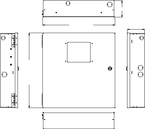
Cabinet Dimensions
Figure 1. PFC-6030 Cabinet Dimensions
TOP |
DEPTH = 3.75 " |
DOOR = 16.07" |
DEPTH = 3.84" |
BACKBOX = 15.77" |
BACKBOX = 16.56"
DOOR = 16.78 "
LEFT SIDE |
RIGHT SIDE |
BOTTOM
DWG #593-1
2-6
PFC-6030 • 5403595 • Rev C • 2/13
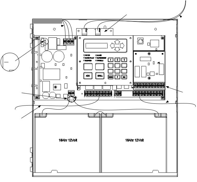
Cabinet Wiring Connections
Figure 2. PFC-6030 Cabinet Wiring
120VAC 50Hz-60Hz  240VAC 50Hz-60Hz
Connect to separate unswitched AC circuits
120 240
120/240 VAC
Jumper Position
Non-power limited battery connection
Non-power limited relay connection
POWER |
|
ALARM |
|
|
|
|
|
|
EARTH FAULT |
|
SUPERVISORY |
|
|
|
|
|
|
SILENCED |
|
TROUBLE |
|
1 |
|
2 |
|
3 |
|
|
|
|
|
|
|
||
|
|
|
|
|
|
|
|
|
SILENCE |
RESET |
4 |
5 |
6 |
|
|
|
||
|
|
7 |
8 |
9 |
Optional
UD-1000 DACT
 High voltage phone connections
Optional CA-6075
 Class A Expander
ACK |
|
DRILL |
|
|
|
|
|
|
|
|
ENTER |
|
0 |
|
ESC |
||
|
|
|
|
|
|
|||
|
|
|
|
|
|
|
|
|
|
|
|
|
|
|
|
|
|
Power limited
 wiring
18Ahr 12Volt |
|
18Ahr 12Volt |
DWG #593-2
2-7

PFC-6030 • 5403595 • Rev C • 2/13
Battery Circuit Calculations
Before selecting the battery, it is important to determine the minimum size batteries for standby and alarm times desired for each application and SLC current draw. If the wrong batteries are installed in a specific application or incorrect current draw used, the proper standby and minimum alarm time will not be present.
The battery circuit is rated for 8 to 55 AH batteries and will operate the panel alarm for at least 24 hours and 5 minutes. The cabinet will house up to two (2) 8 AH or two (2) 18 AH batteries.
Please use the worksheets listed below to calculate the battery size and current draw required for each application and the SLC:
(1) Battery Calculation Worksheet; and (2) SLC Current Draw Worksheet
Battery Calculation Worksheets
|
|
|
|
|
|
|
|
|
|
|
|
|
Standby |
Total |
Alarm |
Total |
|
Description |
|
Quantity |
Alarm |
|||||
|
|
|
|
(mA) |
Standby (mA) |
(mA) |
(mA) |
|
Main board (PFC-6030) |
|
|
1 |
130 |
|
220 |
|
|
|
|
|
|
|
|
|
|
|
LCD Remote RA-6075 |
|
|
|
20 |
|
25 |
|
|
|
|
|
|
|
|
|
|
|
LCD Remote RA-6500 |
|
|
|
20 |
|
50 |
|
|
|
|
|
|
|
|
|
|
|
CA-6075 Class A Expander |
|
|
12 |
|
44 |
|
|
|
UD-1000 DACT |
|
|
|
16 |
|
23 |
|
|
PSN-1000/E Power Expander |
|
|
15 |
|
15 |
|
|
|
|
|
|
|
|
|
|
|
|
LED-16 P-Link |
|
|
|
25 |
|
25 |
|
|
LED-Current (if applicable, see Note 6) |
|
|
15 |
|
100 |
|
|
|
DRV-50 |
|
|
|
25 |
|
25 |
|
|
LED-Current (if applicable, see Note 6) |
|
|
10 |
|
215 |
|
|
|
RLY-5 |
|
|
|
25 |
|
35 |
|
|
Relay Current (if applicable, see Note 6) |
|
|
10 |
|
135 |
|
|
|
FCB-1000 |
|
|
|
25 |
|
25 |
|
|
FIB-1000 |
|
|
|
30 |
|
30 |
|
|
SPG-1000 |
|
|
|
40 |
|
40 |
|
|
NAC 1 |
|
|
|
|
|
|
|
|
|
|
|
|
|
|
|
|
|
NAC 2 |
|
|
|
|
|
|
|
|
|
|
|
|
|
|
|
|
|
SLC Current Draw - (refer to "SLC Current Draw |
|
|
|
|
|
|
||
Worksheet" for calculation) |
|
|
|
|
|
|
|
|
|
|
|
|
Total (ma) |
|
Total (ma) |
|
|
|
|
|
Convert to Amps |
x 0.001 |
Convert to Amps |
x 0.001 |
||
|
(*Refer to maximum allowable standby current) Total A: |
|
Total A: |
|
|
|||
|
|
|
|
|
|
60 minutes per hour |
|
|
|
|
|
|
|
|
Alarm time (minutes) |
|
|
|
|
Multiply by standby hours |
x____ |
Example: |
÷ ____ |
|
||
|
|
|
|
|
|
5 minute alarm: enter 12 |
|
|
|
|
|
|
|
|
10 minute alarm: enter 6 |
|
|
|
|
|
|
|
|
|
|
|
|
|
|
Total Standby AH |
|
Total Alarm AH |
|
|
|
|
|
|
|
|
|
+Total Standby AH |
|
|
|
|
|
|
|
|
Total AH |
|
|
|
|
|
|
|
|
Efficiency Factor |
÷ 0.85 |
|
|
|
|
|
|
|
Required AH |
|
|
|
|
|
|
|
|
|
|
|
*Maximum Allowable Standby Current |
Important Notes: |
|
|
|
|
|
||
1) FACP enclosure can house up to two (2) 18 AH batteries. Larger batteries require accessory |
|
|||||||
(UL 24-Hour standby time) |
|
|||||||
enclosure, part #SSU00500. |
|
|
|
|
||||
7 AH |
.230 A |
|
|
|
|
|||
2) NFPA 72 requires 24 hours of standby power followed by 5 minutes alarm activation. |
|
|||||||
18 AH |
.619 A |
|
||||||
3) NFPA 12, 12A requires 24 hours and five minutes of alarm activation. |
|
|
||||||
33 AH |
1.151 A |
|
|
|||||
4) Door holder circuits configured to disconnect upon AC loss need not be included in the |
|
|||||||
55 AH |
1.930 A |
|
||||||
battery standby calculation since they will not draw power during that time. Door holders |
|
|||||||
|
|
|
||||||
|
|
will contribute to standby current draw when AC is present. |
|
|
||||
|
|
5) Total current must not exceed power supply rating (3.5A). |
|
|
||||
|
|
6) LED/Relay current must be accounted for in the battery calculation for the supplying source. |
|
|||||
|
|
|
|
|
|
|
|
|
2-8

PFC-6030 • 5403595 • Rev C • 2/13
SLC Current Draw Worksheet
|
|
Standby |
Total |
Alarm |
Total |
|
Device Type |
Qty |
Standby |
Alarm |
|||
(mA) |
(mA) |
|||||
|
|
(mA) |
(mA) |
|||
|
|
|
|
|||
Analog photo smoke detector (PSA) |
|
0.325 |
|
0.325 |
|
|
|
|
|
|
|
|
|
Analog photo DUCT smoke detector (DSA) |
|
0.325 |
|
0.325 |
|
|
|
|
|
|
|
|
|
Analog photo smoke / fixed heat detector (PSHA) |
|
0.325 |
|
0.325 |
|
|
|
|
|
|
|
|
|
Analog fixed heat detector (FHA) |
|
0.325 |
|
0.325 |
|
|
|
|
|
|
|
|
|
Analog combo heat detector (RHA) |
|
0.325 |
|
0.325 |
|
|
|
|
|
|
|
|
|
Conventional initiating zone module - 4 inch mount (CIZM-4) *Note 1 |
|
0.325 |
|
1.000 |
|
|
|
|
|
|
|
|
|
Miniature contact module (MCM) |
|
0.325 |
|
0.325 |
|
|
|
|
|
|
|
|
|
Single contact module - 4 inch mount (SCM-4) |
|
0.325 |
|
1.000 |
|
|
|
|
|
|
|
|
|
Dual contact module - 4 inch mount (DCM-4) |
|
0.325 |
|
1.000 |
|
|
|
|
|
|
|
|
|
Monitored output module - 4 inch mount (MOM-4) *Note 2 |
|
0.325 |
|
1.000 |
|
|
|
|
|
|
|
|
|
Twin relay module - 4 inch mount (TRM-4) |
|
0.325 |
|
1.000 |
|
|
|
|
|
|
|
|
|
Short circuit isolator (SCI) |
|
0.325 |
|
2.34 |
|
|
|
|
|
|
|
|
|
Analog sounder base (ASB) *Note 3 |
|
0.325 |
|
0.325 |
|
|
|
|
|
|
|
|
|
Analog relay base (ARB) *Note 4 |
|
0.325 |
|
0.325 |
|
|
|
|
|
|
|
|
|
Isolator base (AIB) |
|
0.325 |
|
2.34 |
|
|
|
|
|
|
|
|
|
SLC alarm LED Current |
n/a |
n/a |
|
n/a |
27.0 |
|
|
|
|
|
|
|
|
|
|
SLC Standby |
|
SLC Alarm |
|
|
|
|
Current |
|
Current |
|
*Note 1: CIZM requires 24VDC power source. Standby current Style D = 4.90 mA, Style B (8.5 mA). Alarm Current = 50.0 mA
*Note 2: MOM requires 24VDC power source. Standby current = 1.60 mA. Alarm Current = 1.60 mA
*Note 3: ASB requires 24VDC power source. Standby current = 5 mA. Alarm Current = 100 mA
*Note 4: ARB requires 24VDC power source. Standby current = 5 mA. Alarm Current = 50 mA
2-9
PFC-6030 • 5403595 • Rev C • 2/13
Isolator Device Load Calculation
This section covers the distinction between an addressable sensor and an isolator to correctly calculate the total SLC device load. A device uses an address and consumes power. Whereas, an isolator does not use an address, but does consume power.
The following scenarios explain how to calculate the current device load based on the SLC configuration.
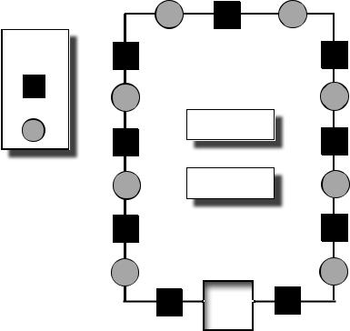
Scenario 1: Class A Loop – Isolated Devices Configuration
In this configuration, each sensor and isolator device / module counts as one (1) when calculating the total device load.
Formula: Total # addressable devices + Total # isolators = Total power unit allocations (or device load)
Figure 3. Example of a Class A Loop – Isolated Branches
LEGEND:
ISO Module/
Device
Sensor
PANEL
DWG # 593-4
Configuration Summary:
Total addressable devices = 8 (sensors only) out of 30 possible addressable points.
Total device load = 17 (calculated as follows: 8 sensors + 9 isolators) out of 127 power unit allocations.
Example: If a configuration uses 30 sensors, up to 97 isolators may be supported.
Solution: 127 - 30 = 97
2-10
PFC-6030 • 5403595 • Rev C • 2/13
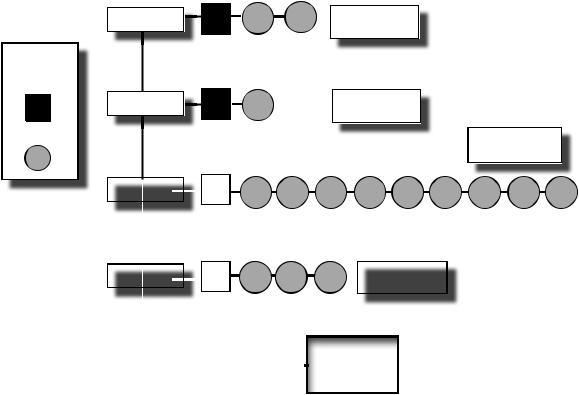
Scenario 2: Class B Loop – Isolated Branch Configuration
In this configuration, there are 4 separate branches each with an isolation device / module and 1 or more sensors. Each sensor requires an address, as shown in Scenario #1 (isolators do not require an address). However, in this scenario, each isolator consumes power equal to 8 devices. To calculate the total device load, refer to the following rule:
Device Load Rule for Branch Configurations
Count all devices, including isolators, on the branch.
•If the count is <=8, allocate 8 as the device load.
•If the count is >8, allocate the actual device count number.
Figure 4. Example of a Class B Loop – Isolated Branches
LEGEND:
ISO Module/
Device
Sensor
|
|
|
|
|
|
|
|
|
|
|
|
|
|
|
|
|
|
|
|
|
|
|
|
|
|
|
|
|
|
|
|
|
|
|
|
|
|
|
|
|
|
|
|
|
|
|
|
|
|
|
|
|
|
|
|
|
|
|
|
|
|
|
|
|
|
|
|
|
|
|
|
|
|
|
|
|
|
|
|
|
|
|
|
|
PANEL |
DWG #593-3 |
|
|
|
|
|
|
|||
|
|
|
|
|
|||
Configuration Summary:
Branch #1 has 3 devices = 8 power allocations
Branch #2 has 2 devices = 8 power allocations
Branch #3 has 10 devices = 10 power allocations
Branch #4 has 4 devices = 8 power allocations
Total addressable devices = 15 (sensors only) out of 30 addressable points.
Total device load = 34 out of a possible 127 power unit allocations.
2-11
PFC-6030 • 5403595 • Rev C • 2/13
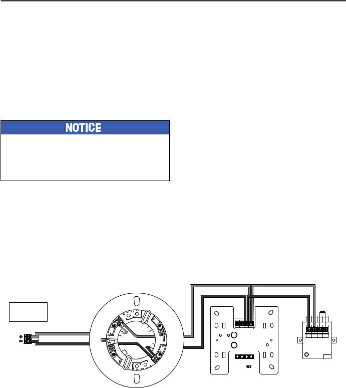
Battery Connections
The battery charging circuit is located on the main panel in the lower left portion of the board. The maximum battery charging circuit is 1.0 amp DC; the charging voltage is approximately 27.3 VDC and is supervised.
Note: The battery should be clearly labeled as “Sealed Lead Acid Battery” or equivalent UL listed or UL Recognized.
Connect the battery wire leads to the terminal connections, as shown. Batteries should be replaced every five (5) years or sooner depending on annual testing.
Figure 5. PFC-6030 Battery Connections
|
|
Panel |
- |
+ |
Connections |
BATTERY |
|
|
|
|
|
|
|
|
|
|
|
|
|
|
|
|
|
|
|
|
|
|
|
|
|
|
|
|
|
|
|
|
|
|
|
|
|
|
|
|
|
|
|
|
|
|
|
|
|
|
- |
|
+ |
|
- |
+ |
||||||||||
|
|
|
12 V |
|
|
|
|
|
|
|
|
12 V |
|||
|
|
|
Battery |
|
|
|
|
|
|
|
Battery |
||||
DWG # 593-5
Main Supply Circuit
The AC terminals are located in the upper left hand portion of the main board. The main board supervises the main AC power and provides indication that the AC power is absent.
Figure 6. PFC-6030 AC Terminals
120VAC 50/60 Hz
240VAC 50/60 Hz Connect to separate Unswitched AC circuit
Black
White
Ground
B W G
AC POWER
AC120V/AC230V,50/60Hz
DWG #593-6
The terminals are rated at 120 VAC/240 VAC 50/60 Hertz and are marked accordingly on the board. The earth ground connection is marked as “G” and is the furthest connection from the line voltage connection.
The AC input power ratings are as follows:
•Maximum of 3A at the nominal 120 VAC rating.
•Maximum of 2A at the nominal 240 VAC rating.
2-12
PFC-6030 • 5403595 • Rev C • 2/13
Section 3: Installation
This section addresses installation procedures for SLCs, NACs and optional modules, including the DACT (UD-1000),
Class A Card, and Remote Annunciators. Wiring requirements and configuration examples are included throughout this section. Instructions for addressing SLC devices which must be completed before programming your system are also included. Please read this section carefully before installing devices and/or modules to insure proper installation.
Note: Instructions for installing the PSN-1000/PSN-1000(E) and/or the IP Dialer accessories are located in Sections 6 and 7, respectively.
Signaling Line Circuit (SLC) Installation
The SLC panel provides power and communication to each of the sensors and modules connected. The SLC is polled by the system every 4–5 seconds. This panel has a loop capacity of 30 addressable points, which may be configured in any combination of smoke sensors, heat detectors, and input or output modules.
All devices require an address prior to connecting to the control panel. Refer to “Addressing SLC Devices” located later in this section for details.
SLC Wiring Requirements
The wiring parameters listed below MUST be followed to ensure proper installation:
•Maximum wiring resistance between two (2) Short Circuit Isolators (SCIs) must be less than 10 ohms.
•Total resistance must be below 50 ohms.
•Maximum wire resistance must be calculated based on 0.1 ohm per SCI.
•Maximum loop capacitance must be 0.5 micro farads.
•All SLC wiring is low voltage and power limited.
Class B, Style 4 Wiring Configuration
Figure 7. Example of SLC Wiring - Class B, Style 4
PFC-6000
Series
SLC Loop (Class B)
Terminal Connections

 7 6
7 6


 8
8
3
Address No. |
|
24- |
|
24+ |
S- |
S+ |
|
|
||||||||||||
|
|
|
|
|
|
Potter Electric Signal Company |
||||||||||||||
|
U |
|
|
|
Conventional Initiating Zone Module |
|||||||||||||||
L |
|
|
|
|||||||||||||||||
|
|
|
|
|
|
Model No. CIZM-4 |
|
|
|
|
|
|||||||||
ALARMFIRE XXXX |
|
|
|
|
|
|
|
Ser. No. xxxxxx |
|
|
|
|
|
|||||||
|
|
|
Document: TN51313e date:XX.XX.2009 |
|||||||||||||||||
|
|
|
|
|
|
Compatibility Identi er: INTE01 |
||||||||||||||
EQUIPMENT |
|
|
|
WARNING |
|
|
|
|
|
|
|
|
||||||||
|
|
|
All Terminals are power limited. |
|||||||||||||||||
|
|
|
|
|
|
Power supply for terminals 24+ and 24must |
||||||||||||||
|
|
|
|
|
|
be power limited |
|
|
|
|
|
|||||||||
|
|
|
|
|
|
|
|
|
|
|
|
|
|
|
|
|
|
|
|
|
|
|
|
|
B- |
|
B+ |
A- |
A+ |
|
|
||||||||||
|
|
|
|
|
|
|
|
|
|
|
|
|
|
|
|
|
|
|
|
|
|
|
|
|
|
|
|
|
|
|
|
|
|
|
|
|
|
|
|
|
|
5.1kΩ
5.1kΩ
S- |
S+ |
C |
NO |
(NC) |
Potter Electric Signal Company
Miniature Contact Module
Model No. MCM
Ser. No. xxxxxx
Document:
TN51314e date: XX.XX.2009
WARNING:
All Terminals are power limited
SIGNALING FIRE ALARM EQUIPMENT
XXXX
UL
LISTED |
Address No. |
DWG # 593-7A
3-13

PFC-6030 • 5403595 • Rev C • 2/13
Class A, Style 6 Wiring Configuration
Figure 8. Example of Class A, Style 6 Requiring CA-6075
S- |
S+ |
S- |
S+ |
S- |
S+ |
24- |
24+ |
S- |
S+ |
Potter Electric Signal Company |
|
Potter Electric Signal Company |
Potter Electric Signal Company |
Potter Electric Signal Company |
|||||
Single Contact Module |
|
Dual Contact Module |
|
|
Twin Relay Module |
Monitored Output Module |
|||
Model No. SCM-4 |
|
Model No. DCM-4 |
|
|
Model No. TRM-4 |
Model No. MOM-4 |
|||
Ser. No. xxxxxx |
|
|
Ser. No. xxxxxx |
|
|
Ser. No. xxxxxx |
Ser. No. xxxxxx |
||
Document: TN51315e date:XX.XX.2009 |
|
Document: TN51316e date:XX.XX.2009 |
Document: TN51317e date:XX.XX.2009 |
Document: TN51318e date:XX.XX.2009 |
|||||
|
|
|
|
|
|
|
WARNING : |
WARNING |
: |
WARNING : |
|
WARNING |
: |
|
|
Terminals S+, S- are power limited. |
Power supply for terminals 24+ and 24must |
||
|
|
|
Terminals NO1, C1, NC1, NO2, C2, NC2 are |
be power limited. |
|||||
All Terminals are power limited. |
|
All Terminals are power limited. |
|
non power limited |
All Terminals are power limited. |
||||
Z NO C |
Z2 |
NO2 |
C2 |
Z1 |
NO1 |
C1 |
NC2 C2 NO2 NC1 C1 NO1 |
A- |
A+ |
(NC2) |
(NC1) |
||||||||
5.1kΩ |
5.1kΩ |
5.1kΩ |
5.1kΩ |
5.1kΩ |
5.1kΩ |
PFC-6000
Series
SLC Loop (Class A)
Terminal Connections
5.1kΩ
6


3
 7
7

 8
8
2424+ |
S- |
S+ |
|
|
|
|
|
|
Potter Electric Signal Company |
S- |
S+ |
C |
NO |
||
|
Conventional Initiating Zone Module |
||||||
|
No. CIZM-4 |
|
(NC) |
||||
|
Model Ser. No. xxxxxx |
|
|
||||
|
Document: TN51313e date:XX.XX.2009 |
Potter Electric Signal Company |
|||||
|
Compatibility Identi er: INTE01 |
Miniature Contact Module |
|
||||
|
WARNING |
: |
|
Model No. MCM |
|
|
|
|
Power supply for terminals 24+ and 24must |
|
Ser. No. xxxxxx |
|
|||
|
be power limited |
|
Document: |
|
|
||
|
All Terminals are power limited. |
|
TN51314e date: XX.XX.2009 |
||||
B- |
B+ |
A- |
A+ |
WARNING: |
|
|
|
All Terminals are power limited |
|||||||
|
|
|
|
UL |
|
|
|
|
|
5.1kΩ |
DWG #593-8 |
||||
Notes:
1.The Class A, Style 6 configuration does not provide the level of protection as Class A, Style 7.
2.Class A, Style 7 requires installation of a CA-6075.
3.The use of a SCI or AIB is not required.
4.The SLC connection requires that the wires are separated 10’, installed in conduit or other mechanical protection.
5.Maximum wiring resistance must not exceed 50 ohms.
Class A, Style 7 Wiring Configuration
Figure 9. Example of SLC Wiring - Class A, Style 7 Requiring CA-6075
S-2 S+2 |
S-1 S+1 |
S- |
S+ |
S-2 S+2 |
S-1 S+1 |
Potter Electric Signal Company |
Potter Electric Signal Company |
Potter Electric Signal Company |
||||
Short Circuit Isolater |
Dual Contact Module |
|
|
Short Circuit Isolater |
||
Model No. SCI |
Model No. DCM-4 |
|
|
Model No. SCI |
||
Ser. No. xxxxxx |
|
Ser. No. xxxxxx |
|
|
Ser. No. xxxxxx |
|
Document: TN51313e date:XX.XX.2009 |
Document: TN51316e date:XX.XX.2009 |
Document: TN51313e date:XX.XX.2009 |
||||
WARNING : |
WARNING |
: |
|
|
WARNING : |
|
All Terminals are power limited. |
All Terminals are power limited. |
|
All Terminals are power limited. |
|||
Z2 |
NO2 |
C2 |
Z1 |
NO1 |
C1 |
|
(NC2) |
(NC1) |
|
||||
|
SCI |
5.1kΩ |
5.1kΩ |
SCI |
PFC-6000 |
|
|
|
|
Series |
|
|
|
|
SLC Loop (Class A Style 7) |
|
|
|
|
Terminal Connections |
|
|
|
|
S-2 S+2 S-1 S+1 |
2424+ |
S- |
S+ |
S-2 S+2 S-1 S+1 |
Potter Electric Signal Company |
Potter Electric Signal Company |
Potter Electric Signal Company |
||
Short Circuit Isolater |
Conventional Initiating Zone Module |
Short Circuit Isolater |
||
Model No. SCI |
Model No. CIZM-4 |
|
Model No. SCI |
|
Ser. No. xxxxxx |
Ser. No. xxxxxx |
|
Ser. No. xxxxxx |
|
Document: TN51313e date:XX.XX.2009 |
Document: TN51313e date:XX.XX.2009 |
Document: TN51313e date:XX.XX.2009 |
||
Compatibility Identi er: INTE01 |
||||
|
WARNING |
: |
|
|
WARNING : |
Power supply for terminals 24+ and 24must |
WARNING : |
||
be power limited |
|
|||
All Terminals are power limited. |
All Terminals are power limited. |
All Terminals are power limited. |
||
|
B- B+ |
A- |
A+ |
|
SCI |
5.1kΩ |
SCI |
DWG #593-9
Notes:
1.The Class A, Style 7 requires installation of an isolator close nipple connected to every module or sensor. Isolators may be either a SCI or an AIB addressable base.
2.Class A, Style 7 requires installation of a CA-6075.
3.The SLC connection requires that the wires are separated by a minimum of 10’and installed in conduit or other mechanical protection.
4.Maximum wiring resistance must not exceed 50 ohms.
3-14
PFC-6030 • 5403595 • Rev C • 2/13
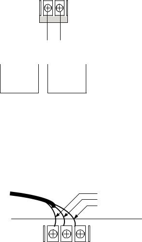
Connecting Analog Detectors
When installing analog detectors, such as a photoelectric smoke sensor (PSA), photo smoke/fixed heat detector (PSHA), heat detector (FHA), or an analog combination type heat detector (RHA), use detector bases (i.e. AB-6). An analog detector activates its response LED when activated. An example of wiring an analog detector is shown below.
Figure 10. Analog Detector Wiring Example
S+ |
S+ |
From FACP or the previous |
|
To the next addressable device |
|
addressable device on the SLC loop |
|
||
S- |
S- |
||
|
DWG #593-10
Connecting Addressable Modules
This section provides examples of wiring addressable modules, including Conventional Initiating Zones (CIZM-4), Miniature Contact (MCM), Single Contact (SCM-4), Dual Contact Module (DCM-4), Twin Relay (TRM-4), Monitored Output (MOM-4), Analog Relay (ARB), Analog Sounder Base (ASB), and Addressable Pull Station (APS) modules.
Conventional Initiating Zones (CIZM-4) Class A |
|
|
|
|
||
Figure 11. CIZM-4, Class A |
Note: The resistance of external wiring shall be less that 100Ω. |
|
|
|
||
From FACP or |
|
|
|
|||
capacitance of external wiring shall be less than 1 micro farads. |
|
|
||||
Previous Module |
|
Select Style D |
|
|
Conventional |
|
|
|
|
|
|||
|
JP1 |
|
|
Detector |
||
SLC Loop |
|
|
|
|||
|
|
|
|
|
||
To Next Module |
S+ |
B+ |
|
|
|
|
S- |
B- |
+ |
+ |
+ |
||
|
||||||
From FACP |
24+ |
A+ |
||||
24- |
A- |
|
|
|
||
or Previous Module |
_ |
_ |
_ |
|||
|
|
|||||
|
|
LED |
||||
|
|
|
|
|
||
|
Conventional Initiating Zone Module |
|
|
|
||
|
Model No. CIZM-4 |
|
|
|
|
|
To Next |
|
|
|
|
|
|
Module |
|
|
|
|
|
|
|
|
|
|
|
DWG #593-11 |
|
Notes:
1.The resistance of external wiring shall be less than 100 ohms.
2.The capacitance of external wiring shall be less than 1 micro F.
3.In this style, the open circuit “trouble condition” of IDC is latched at the control panel until system is reset. Therefore, the system MUST be reset at the control panel after clearing the open circuit condition at the site.
4.Refer to the CIZM data sheet for information on compatible devices.
3-15

PFC-6030 • 5403595 • Rev C • 2/13
Conventional Initiating Zones (CIZM-4) Class B
Figure 12. CIZM-4, Class B
From FACP or |
|
|
Select Style B |
|
|
|
Previous Module |
|
|
|
Conventional |
||
|
|
JP1 |
|
|
||
SLC Loop |
|
|
|
Detector |
||
|
|
|
|
|||
|
S+ |
B+ |
|
|
|
|
To Next Module |
S- |
B- |
+ |
+ |
+ |
|
From FACP or |
24+ |
A+ |
||||
|
|
|
||||
Previous Module |
24- |
A- |
_ |
_ |
_ |
|
|
|
|||||
|
|
LED |
||||
|
|
|
|
|
||
|
nventional Initiating Zone Module |
|
|
|
||
|
Model No. CIZM-4 |
|
|
|
|
|
To Next Module |
|
|
Note: The resistance of external wiring shall be less that 100Ω. |
|||
|
|
|
||||
|
|
|
The capacitance of external wiring shall be less than 1 micro farads. |
|||
5.1KΩ 1/2W EOLR
DWG #593-12
Miniature Contact Module (MCM)
Refer to the figure shown below for a MCM wiring example.
Figure 13. MCM Wiring Example
To Next Module
SLC Loop
From FACP or Previous Module
|
Note: The resistance of external wiring shall be less that 100Ω. |
|
The capacitance of external wiring shall be less than 1 micro farads. |
|
5.1KΩ 1/2W EOLR |
NO |
|
COM |
|
S+ |
|
S- |
|
Mini Contact Module |
DWG #593-13 |
Model No. MCM |
Note: If MCM is located in an electrical box, it should be secured using crew tabs or other method to prevent movement.
Single Contact Module – 4 inch Mount (SCM-4)
Refer to the figure shown below for a SCM-4 wiring example.
Figure 14. SCM-4 Wiring Example
To Next Module
SLC Loop
From FACP or Previous Module
Note: The resistance of external wiring shall be less that 100Ω.
The capacitance of external wiring shall be less than 1 micro farads.
COM
S+
NO
S-
Z
 LED
LED
Single Contact Module
Model No. SCM-4
5.1KΩ 1/2W EOLR
DWG #593-14
3-16
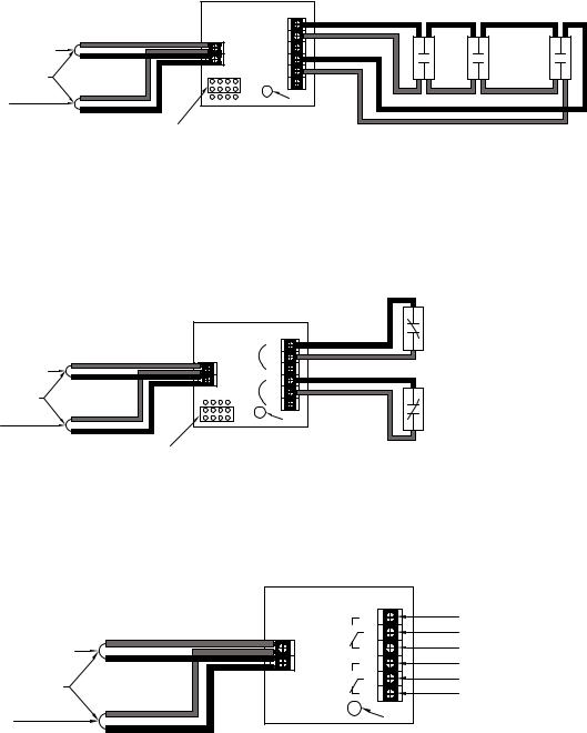
PFC-6030 • 5403595 • Rev C • 2/13
Dual Contact Module – 4 inch Mount (DCM-4)
Refer to the figure shown below for a Class A DCM-4 wiring example.
Figure 15. DCM-4 with One Class A Circuit
|
Dual Contact Module |
|
|
Model No. DCM-4 |
NO1 |
|
|
C1 |
From FACP or Previous Module |
S+ |
Z1 |
|
S- |
NO2 |
SLC Loop |
JP1 |
C2 |
|
Z2 |
|
|
|
|
To Next Module |
|
LED |
|
|
|
|
Select Style 6 |
|
Note: The resistance of external wiring shall be less that 100Ω.
The capacitance of external wiring shall be less than 1 micro farads.
DWG #593-15
Note: In this configuration, the DCM-4 operates as a single point Class A module.
When configuring a Class B, the DCM-4 has two (2) addresses. If address No.1 is set, input circuit No.1 (NO1, C1) will be addressed as No.1, and input circuit No.2 (NO2, C2) will automatically be addressed as No.2. Refer to the figure below for an example of wiring a Class B DCM-4.
Figure 16. DCM-4 with Two Class B Circuits
Note: The resistance of external wiring shall be less that 100Ω.
The capacitance of external wiring shall be
|
Dual Contact Module |
|
|
Model No. DCM-4 |
NO1 |
|
Address # |
C1 |
From FACP or Previous Module |
S+ |
Z1 |
|
S- |
NO2 |
SLC Loop |
JP1 Address #+1 |
C2 |
|
Z2 |
|
|
|
|
To Next Module |
|
LED |
|
|
|
|
Select Style 4 |
DWG #593-16 |
|
|
|
Twin Relay Module – 4 inch mount (TRM-4)
The TRM-4 has two (2) contacts that are active simultaneously when TRM-4 is in the active mode. Normal output is nonpowerlimited, unless the power supply connected to the TRM-4 is power-limited and the circuits are power-limited.
Figure 17. Example of TRM-4 Wiring
|
Contact Rating: |
|
|
|
|
24VDC / 2.0A |
|
|
|
|
125VAC / .5A |
NO1 |
|
Normally Open 1 |
|
|
C1 |
|
Common 1 |
From FACP or Previous Module |
S+ |
NC1 |
|
Normally Closed 1 |
|
S- |
NO2 |
|
Normally Open 2 |
SLC Loop |
|
C2 |
|
Common 2 |
|
NC2 |
|
Normally Closed 2 |
|
|
Twin Relay Module |
|
||
|
|
|
|
|
To Next Module |
Model No. TRM-4 |
|
LED |
|
|
|
DWG. #593-17 |
||
|
|
|
3-17

PFC-6030 • 5403595 • Rev C • 2/13
Monitored Output Module – 4 inch mount (MOM-4)
If the power supply connected to the MOM-4 is power limited, then the outputs are power limited. An example of a MOM-4 wired as a conventional application is shown here.
Figure 18. Example of MOM-4 with NAC Connections
From FACP or Previous Module |
|
|
|
|
JP1 |
|
Select DC |
SLC Loop |
|
|
|
|
|
Output Rating: |
|
|
|
|
|
|
S+ |
|
24VDC / 2.0A |
To Next Module |
|
|
|
S- |
A+ |
|
|
|
|
||
From FACP or Previous Module |
24+ |
A- |
+ |
|
24- |
|
|
|
|
LED |
_ |
|
Monitored Output Module |
|
|
|
Model No. MOM-4 |
|
|
To Next Module |
|
|
|
|
Noti cation Appliance |
|
+ |
+ |
5.1KΩ 1/2W EOLR |
|
|
_ _
DWG #593-18
Analog Sounder Base (ASB)
Figure 19. Example of Analog Sounder Base Wiring
|
SLC Loop |
|
24 VDC+ |
24 VDC- |
To Next Module |
24 VDC- |
24 VDC+ |
|
From FACP or |
|
|
Previous Module |
S+ |
24+ |
|
||
SLC Loop |
S- |
24- |
|
S+ |
|
|
S- |
|
TB1 |
Analog Sounder Base |
|
|
|
Model No. ASB |
DWG #593-19
Notes:
1.The supply power must be coded in order for the output to be coded.
2.ASB does not generate a coded output. It will track the pattern delivered to its 24 VDC input.
Analog Relay Base (ARB)
Figure 20. Example of Analog Relay Base Wiring
SLC Loop 

From FACP or |
|
|
|
SLC Loop |
|
|
|
|
|
To Next Module |
|
Previous Module |
24+ |
NO1 |
|
24 VDC- |
|
|
|
||||
24 VDC- |
|
|
|||
24- |
C1(8A) |
|
24 VDC+ |
|
|
24 VDC+ |
S+ |
NC1 |
|
|
|
|
|
|
|
||
|
S- |
NO2 |
|
|
|
|
S+ |
C2(2A) |
|
|
|
|
S- |
NC2 |
NO1 |
|
|
|
TB1 |
TB2 |
|
8.0A / 240VAC |
|
|
|
|
C1(8A) |
|
|
|
|
|
|
8.0A / 30VDC |
|
|
|
LED |
NC1 |
|
|
|
|
|
|
||
|
|
Analog Relay Base |
NO2 |
|
|
|
|
Model No. ARB |
|
2.0A / 240VAC |
|
|
|
|
|
||
|
|
|
C2(2A) |
|
|
|
|
|
|
2.0A / 30VDC |
|
|
|
|
|
|
|
|
|
|
NC2 |
|
|
|
|
|
|
TB2 |
|
|
|
|
|
|
DWG #593-20 |
3-18

PFC-6030 • 5403595 • Rev C • 2/13
Single Action / Dual Action Pull Station (APS-SA / APS-DA)
The APS-SA/DA addressable pull stations are non-coded that provide an addressable point to the panel. The APS pull stations have terminals that allow the SLC to be wired directly to the device and then exit to the next device in the loop. Refer to the wiring example shown below.
Figure 21. Example of Addressable Pull Station Wiring
NO C S+ S- |
Addressable Pull |
Station - Single Action/ |
Dual Action |
Model No. APS-SA/DA |
|
FACTORY WIRED |
|
|
CONTACTS |

 From FACP or Previous Module
SLC Loop
To Next Module
DWG #593-36
3-19

PFC-6030 • 5403595 • Rev C • 2/13
Addressing SLC Devices
Before devices can be programmed, they must be assigned a unique address. There are two (2) methods to address devices:
(1) You may use a hand-held address setting device or (2) Use the panel's System Tools – SLC Addr Prog option. Only authorized system users may access the System Tools options. You may sequentially address individual devices or groups of devices and assign different numerical ranges (i.e., #1-10, and 15-25) as necessary.
To address devices via a hand-held address device:
1.Connect the device to the base on the hand-held address device or to the terminals with a pair of wires to connect modules.
2.Use the buttons on the device to set the address, and press Enter to complete addressing device.
3.Repeat steps for each device.
Note: The "R22" LED is selected by default; if the "R22" LED is not lit, press Power until it is reselected.
To address devices from the Panel:
1.Press ENTER to display Main Menu.
2. |
Press 5 to access System Tools (or press the down arrow to display 5=System Tools). |
|
|
Main Menu |
|||
|
yy Press ENTER to select. The “Enter Code” prompt displays. |
1=View History |
|
|
yy Enter the applicable user code on keypad to continue. |
2=Enable/Disable |
|
|
Note: User code displays **** (asterisks) on LCD panel. |
3=Set Date/Time |
|
|
4=Walk Test |
||
|
yy The System Tools menu displays. |
5=System Tools |
|
|
1=SLC Tools |
||
3. |
Press 1 to select SLC Tools. |
1=SLC Pinpoint |
|
2=SLC Stats |
|||
|
|
||
4. |
Press 3 to select SLC Addr Prog. The prompt “Enter key will Shutdown System” |
3=SLC Addr Prog |
|
|
displays on LCD panel, and emits beeping until acknowledged. |
1=Single device |
|
|
|
2=Mltp device |
5.Press ENTER to shutdown (or press ESC to exit SLC Addr Prog).
The SLC Addr Prog menu displays:
3=SLC Addr Prog
1=Single device 2=Mltp device
Next, you must connect the device's cable to the panel's SLC PGM terminals (as shown below).
Figure 22. Example of Control Panel Showing SLC Program Terminals
POWER |
|
ALARM |
|
|
|
|
|
|
EARTH FAULT |
|
SUPERVISORY |
|
|
|
|
|
|
SILENCED |
|
TROUBLE |
|
1 |
|
2 |
|
3 |
|
|
|
|
|
|
|
|
|
|
|
|
|
|
|
|
|
|
SILENCE |
RESET |
4 |
5 |
6 |
|
|
|
||
|
|
7 |
8 |
9 |
ACK |
DRILL |
ENTER |
0 |
ESC |
|
|
SLC Program
Terminals
DWG #593-21
3-20
PFC-6030 • 5403595 • Rev C • 2/13
For a Single Device:
1.From the SLC Addr Prog menu, press 1 to address a Single device.
2.Attach connector wires to SLC PGM terminals, if not already done. The “Connect Device” prompt displays.
3.Connect device. The “Found Address: xx” prompt displays.
yy Modify new address, if needed, or press ENTER to continue.
yy The “Writing Addr: XX” prompt displays, and the system beeps three (3) times when completed. When addressing is completed, the “Found Addr: XX, New Addr: XX” prompt displays.
yy Disconnect device, and continue with next device. yy Repeat steps, as needed.
4.Press ESC when finished.
For Multiple Devices:
1.From the SLC Addr Prog menu, press 2 to address Mult device.
•The “Start Address: XX” prompt displays.
•Modify starting address, if needed, and press ENTER.
•The prompt “Connect Device” displays.
2.Connect 1st device. The “Addr = XX Next = XX Remove” prompt displays.
•Disconnect the device, connect next device. Addressing is completed when the panel emits a series of three (3) beeps.
•The “Addr = XX Next = XX Remove” prompt displays.
•Continue with next device, following prompts.
Notes:
•The prompt “Addr = XX” refers to the current device number, and “Next = XX” is the next sequential address number.
•When configuring a Class B DCM-4, press the UPARROW to skip the next sequential number. The Class B DCM-4 requires 2 addresses; if this isn't done, the next available address will be assigned to a different device and the DCM-4 will operate as a single point device.
3.Press ESC when finished.
3-21
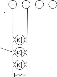
PFC-6030 • 5403595 • Rev C • 2/13
Notification Appliance Circuits Installation
There are two (2) NAC circuits provided on the PFC-6030 rated as continuous 3 amps at 24 VDC. The NAC circuits may be configured for Class A or Class B. (Please refer to the Class A and B wiring examples located in this section.)
NAC Wiring
yy Outputs are supervised and regulated. yy Circuits are power limited.
yy Type of NAC output is selectable, and may be configured for strobe synchronization with Potter/AMSECO, Cooper Wheelock®, Gentex®, or System Sensor® strobe devices. Refer to the listing of compatible models located in the
“NAC Compatibility Document”, Potter #5403592, for this information.
yy The CA-6075 Class-A Expander may be programmed to allow for operation of the NACs. The expander adheres to the same circuit rating, supervision and regulation as other circuits.
NAC Maximum Wiring Impedance Formula
The maximum impedance is a function of the load placed on the circuit. To calculate the maximum line current impedance, use the following formula:
(Alarm Current of Notification Appliances) x (Wire Resistance) < 3 Volts
NAC Wiring Configurations
Examples of Class B and Class AWiring follow.
Figure 23. NAC Class B Wiring Example
|
|
|
|
|
|
|
|
|
|
|
|
|
|
|
|
|
|
|
|
|
|
|
|
|
|
|
|
|
|
|
|
|
|
|
|
|
|
|
|
|
|
|
|
|
|
|
|
|
|
|
|
|
|
|
|
|
|
|
|
|
|
|
|
|
|
|
|
|
|
|
|
|
|
|
|
|
|
|
|
|
|
|
|
|
|
|
|
|
|
|
|
|
|
|
NAC 1 |
|
|
|
|
|
|
NAC 2 |
||||||||||||
- |
+ |
- |
+ |
|
|
|
||||||||||||||||
|
|
|
|
|
|
|
|
|
|
|
|
|
|
|
|
|
|
|
|
|
|
|
Notification
Appliance
5.1k EOL |
DWG #602-4A |
Potter Part #3005013 |
Notes:
1.The Potter part number for the listed end of line assembly is #3005013 EOL Resistor Assembly.
2.The panel has ground fault detection on the NAC circuits. The impedance to ground for ground fault detection is 0 ohms.
3-22

PFC-6030 • 5403595 • Rev C • 2/13
Figure 24. NAC Class A Wiring Example
|
NAC 1 |
NAC 2 |
|
- |
+ |
- |
+ |
NAC 1 |
NAC 2 |
||
- |
+ |
- |
+ |
CA-6075 Class A card
Notification
Appliance
DWG #602-5A
3-23
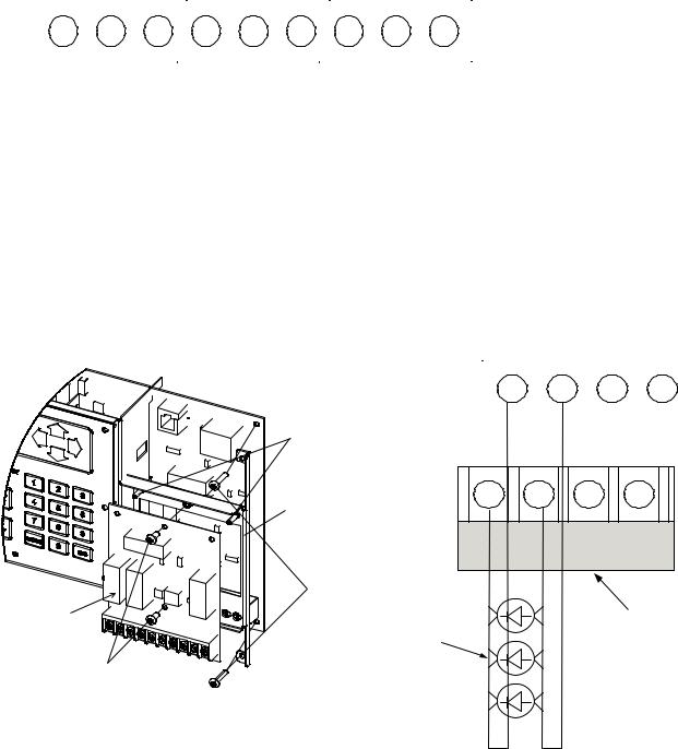
PFC-6030 • 5403595 • Rev C • 2/13
Relay Output Wiring
The panel has three (3) dedicated common relays. The dedicated trouble relay is a fail safe trouble relay that changes position anytime a trouble condition occurs.
Relays have a contact rating of 24VDC / 3.0A, 125VAC / 3A, and Power Factor of 1.0. These outputs are non-power limited and not supervised.
Note: If the power supply connected to the devices is power-limited, then the outputs are power limited.
Figure 25. Relay Outputs
|
|
|
|
|
|
|
|
|
|
|
|
|
|
|
|
|
|
|
|
|
|
|
|
|
|
|
|
|
|
|
|
|
|
|
|
|
|
|
|
|
|
|
|
|
|
|
|
|
|
|
|
|
|
|
|
|
|
|
|
|
|
|
|
|
|
|
|
|
|
|
|
|
|
|
|
|
|
|
|
|
|
|
|
|
|
|
|
|
|
|
|
|
|
|
|
|
|
|
|
|
|
|
|
|
|
|
|
|
|
|
|
|
|
|
|
|
|
|
|
|
|
|
|
|
|
|
|
|
|
|
|
|
|
|
|
|
|
|
|
|
|
|
|
|
|
|
|
|
|
|
|
|
|
|
|
|
|
|
|
|
|
|
|
|
|
|
|
|
|
|
|
|
|
|
|
|
|
|
TROUBLE |
|
|
SUPERVISORY |
|
|
|
|
|
ALARM |
|||||||||||||||||||||||||||||||
|
NC COM NO |
|
NC COM NO |
|
NC COM NO |
||||||||||||||||||||||||||||||||||||||
|
|
|
|
|
|
|
|
|
|
|
|
|
|
|
|
|
|
|
|
|
|
|
|
|
|
|
|
|
|
|
|
|
|
|
|
|
|
|
|
|
|
|
|
|
|
|
|
|
|
|
|
|
|
|
|
|
|
|
|
|
|
|
|
|
|
|
|
|
|
|
|
|
|
|
|
|
|
|
|
DWG #593-26 |
|||||||
CA-6075 Class A Expander Installation
The Class A configuration requires the use of the CA-6075. Once the card is installed, the additional terminals are provided for the return loop of the NAC. The CA-6075 provides the terminals for both NACs, SLCs, and P-Link. Refer to the figures below for examples of installing and wiring a Class A expander card.
Notes:
1.One (1) CA-6075 Class A expander may be installed per panel.
2.The CA-6075 provides the terminals for NACs, P-Link, and SLCs.
Figure 26. Examples of Installing and Wiring a Class A Expander Card
guide pins
5050793 bracket
|
|
|
|
|
|
|
|
|
|
|
|
|
|
|
|
|
|
|
|
|
|
|
|
|
|
|
|
|
|
|
|
|
|
|
|
|
|
|
|
|
|
|
|
|
|
|
|
|
|
|
|
|
|
|
|
|
|
|
|
|
|
|
|
|
|
|
|
|
|
|
|
|
|
|
|
|
|
|
|
|
|
|
|
|
|
|
|
|
|
|
|
|
|
|
|
|
|
|
|
|
|
|
|
|
|
|
|
|
|
|
|
|
|
|
|
|
|
|
|
|
|
|
|
|
|
|
|
|
|
|
|
|
|
|
|
|
|
|
|
|
|
|
|
NAC 1 |
|
|
|
|
|
|
|
|
NAC 2 |
|
|
||||||||||||||
|
- |
+ |
- |
|
|
|
+ |
|
|
|
|
|
|||||||||||||||||||||
|
|
|
|
|
|
|
|
|
|
|
|
|
|
|
|
|
|
|
|
|
|
|
|
|
|
|
|
|
|
|
|
|
|
|
|
|
|
|
|
|
|
|
|
|
|
|
|
|
|
|
|
|
|
|
|
|
|
|
|
|
|
|
|
|
|
|
|
|
|
|
|
|
|
|
|
|
|
|
|
|
|
|
|
|
|
|
|
|
|
|
|
|
|
|
|
|
|
|
|
|
|
|
|
|
|
|
|
|
|
|
|
|
|
|
|
|
|
|
|
|
|
|
|
|
|
|
|
|
|
|
|
|
|
|
|
|
|
|
|
|
|
|
|
|
|
|
|
|
|
|
|
|
|
|
|
|
|
|
|
|
|
|
|
|
|
|
|
|
|
NAC 1 |
NAC 2 |
||
- |
+ |
- |
+ |
|
#6-32 x 7/8 screws |
CA-6075 |
CA-6075 Class A card |
Class A Expander |
Notification |
|
Appliance |
#6-32 x 1/4 screws |
DWG #593-27 |
DWG #602-5A
3-24
 Loading...